Installation Instructions for: INTERCOOLED...
49
Step-by-step instructions for installing the best in supercharger systems. Installation Instructions for: INTERCOOLED SUPERCHARGER SYSTEM 2005-2006 PONTIAC GTO LS2 Magnuson Products Inc 1990 Knoll Drive, Ventura, CA. 93003 (805) 289-0044 * (805) 677-4897 fax magnusonproducts.com * magnacharger.com ATTENTION! Y our MAGNA CHARGER intercooler kit is sensitive to corrosion! Take care of if by using 50/50 anti-freeze with de-ionized water. 89-89-60-014 Rev D
-
Upload
nguyenlien -
Category
Documents
-
view
225 -
download
2
Transcript of Installation Instructions for: INTERCOOLED...
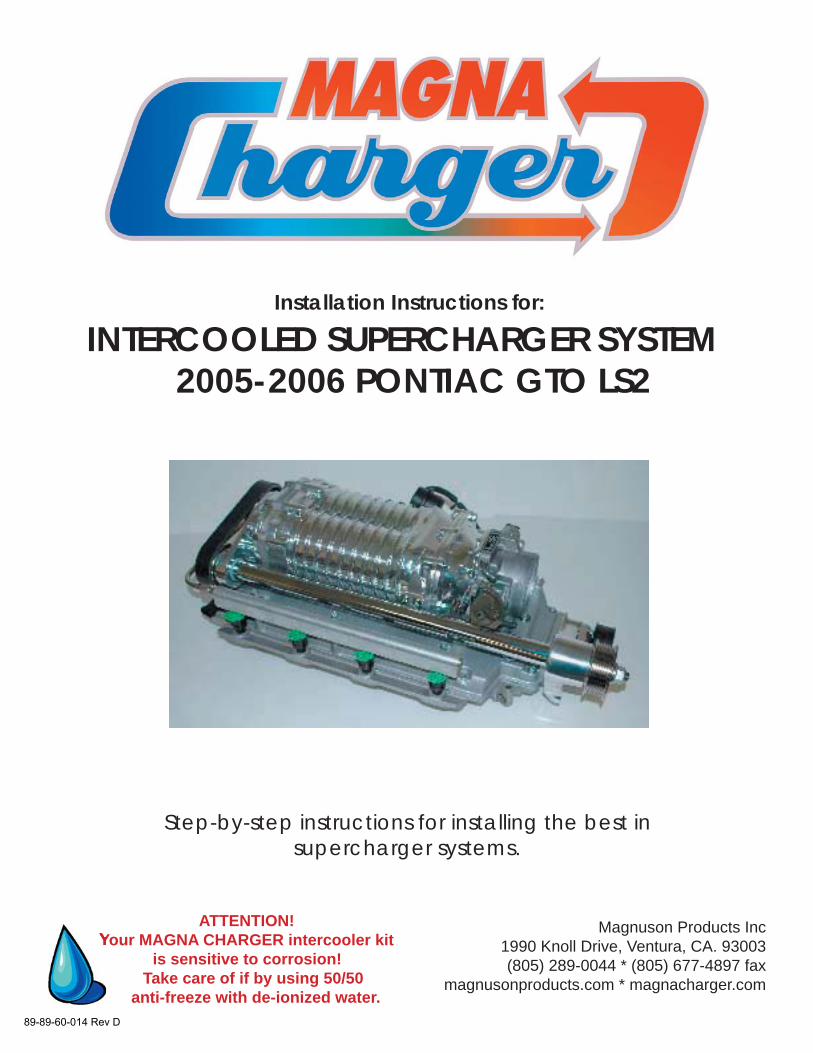
Step-by-step instructions for installing the best in supercharger systems.
Installation Instructions for:
INTERCOOLED SUPERCHARGER SYSTEM 2005-2006 PONTIAC GTO LS2
Magnuson Products Inc1990 Knoll Drive, Ventura, CA. 93003(805) 289-0044 * (805) 677-4897 fax
magnusonproducts.com * magnacharger.com
ATTENTION!Your MAGNA CHARGER intercooler kit
is sensitive to corrosion! Take care of if by using 50/50
anti-freeze with de-ionized water.89-89-60-014 Rev D
INSTALLATION MANUALMagna Charger
GM 6.0 LS2 Liter Engines, 2005 and later Pontiac GTO
Please take a few moments to review this manual thoroughly before you begin work, as there are special steps for both the LS1 (2004) and LS2 (2005-on) equipped vehicles: Μake quick parts check to make certain your kit is complete (see shipper parts list in this package). If you discover shipping damage or shortage, please call our offi ce immediately. Take a look at exactly what you are going to need in terms of tools, time, and experience. Review our limited warranty with care. When unpacking the supercharger kit DO NOT lift the supercharger assembly by the black plastic bypass actuator. This is pre-set from the factory and can be altered if used as a lifting point!
Caution: Relieve the fuel system pressure before servicing fuel system components in order to reduce the risk of fi re and personal injury. After relieving the system pressure, a small amount of fuel may be released when servicing the fuel lines or connections. In order to reduce the risk of personal injury, cover the regulator and fuel line fi ttings with a shop towel before disconnecting. This will catch any fuel that may leak out. Place the towel in an approved container when the job is complete. Use only premium fuel, 91 octane or better.
Magna Charger systems are manufactured to produce about 20 RWHP per pound of boost at sea level. High altitudes will produce different numbers.
Our Magna Charger kits are designed for engines in good mechanical condition only. Installation on high mileage or damaged engines is not recommended and may result in engine failure, for which we are not responsible. Magna Charger is not responsible for the engine or consequential damages.
Aftermarket engine re-calibration devices that modify fuel and spark curve (including, but not limited to programmers) are not recommended and may cause engine damage or failure. Use of non-Magna Charger approved programming will void all warranties. If you have any questions, call us.
After you fi nish your installation and road test your vehicle, please fi ll out and mail in the limited warranty card, so we can add you to our fi les (this is important for your protection).
A new GM fuel fi lter is recommended at the time of supercharger installation. Stock spark plugs and stock plug gap is recommended Drive belt = Gates# K061010 Air Filter = K&N# 33-2289
Tools Required: Metric wrench set 1/4” - 3/8” and 1/2” drive metric socket set (Standard & Deep) 3/8” and 1/2” drive Foot pound and inch pound torque wrenches Phillips and fl at head screwdrivers Fuel line quick disconnect tools (included in kit) Small or angled 3/8 drill motor Drain pan Hose cutters Hose clamp pliers Safety glasses Metric Allen socket set 3/8 drive Shop vacuum cleaner
Contact information:Magnuson Products IncMagna Charger Division1990 Knoll DriveVentura, CA 93003Sales/Tech support 805-289-0044Web sites:www.magnusonproducts.comwww.magnacharger.comE-mail:[email protected]
7/07Page 2
2005-2006 Pontiac GTO LS2 Supercharger Installation Instructions magnacharger.com
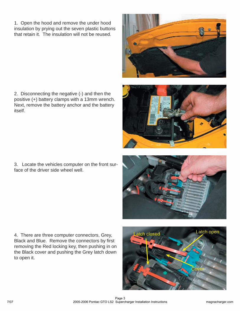
2. Disconnecting the negative (-) and then the positive (+) battery clamps with a 13mm wrench. Next, remove the battery anchor and the battery itself.
1. Open the hood and remove the under hood insulation by prying out the seven plastic buttons that retain it. The insulation will not be reused.
3. Locate the vehicles computer on the front sur-face of the driver side wheel well.
4. There are three computer connectors, Grey, Black and Blue. Remove the connectors by fi rst removing the Red locking key, then pushing in on the Black cover and pushing the Grey latch down to open it.
Latch closed Latch open
Cover
7/07Page 3
2005-2006 Pontiac GTO LS2 Supercharger Installation Instructions magnacharger.com
7. Note: If your vehicle has a automatic transmis-sion, you will also need to remove the transmis-sion control computer located on the back side of the drivers kick panel, inside the vehicle.
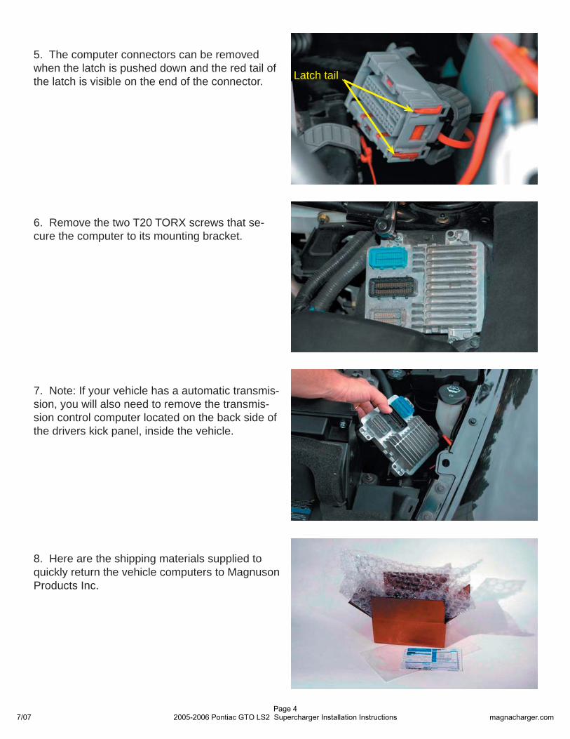
5. The computer connectors can be removed when the latch is pushed down and the red tail of the latch is visible on the end of the connector.
8. Here are the shipping materials supplied to quickly return the vehicle computers to Magnuson Products Inc.
6. Remove the two T20 TORX screws that se-cure the computer to its mounting bracket.
Latch tail
7/07Page 4
2005-2006 Pontiac GTO LS2 Supercharger Installation Instructions magnacharger.com
12. Remove the strut tower brace and fasteners from the vehicle, the brace can be reinstalled after the supercharger installation.
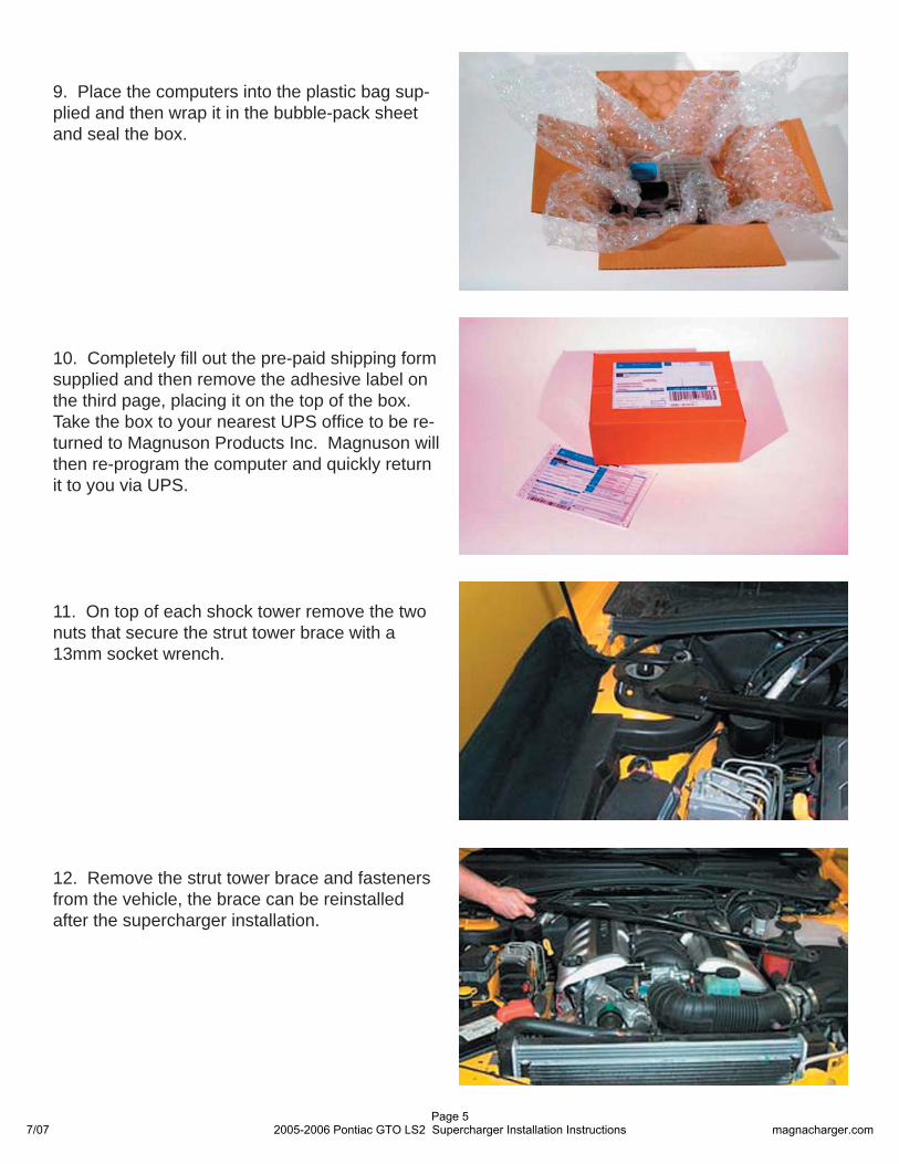
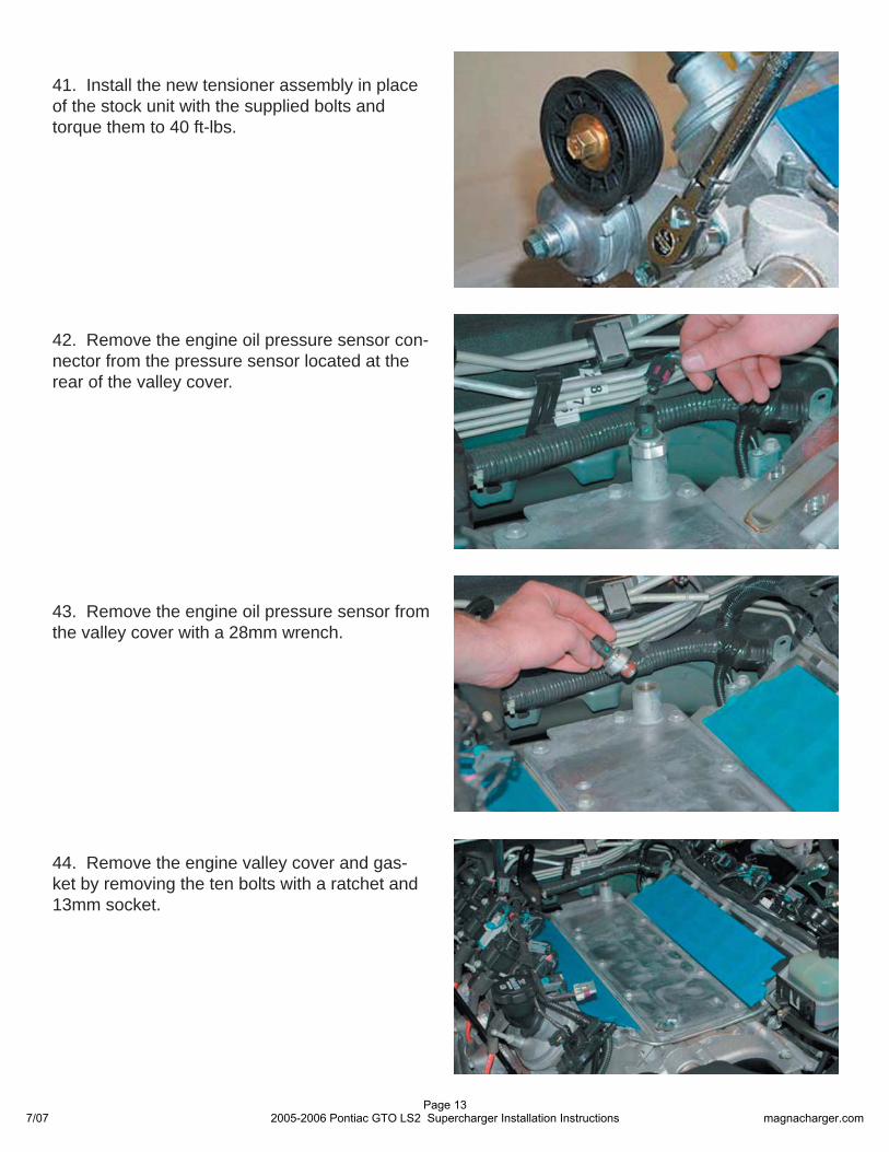
11. On top of each shock tower remove the two nuts that secure the strut tower brace with a 13mm socket wrench.
10. Completely fi ll out the pre-paid shipping form supplied and then remove the adhesive label on the third page, placing it on the top of the box. Take the box to your nearest UPS offi ce to be re-turned to Magnuson Products Inc. Magnuson will then re-program the computer and quickly return it to you via UPS.
9. Place the computers into the plastic bag sup-plied and then wrap it in the bubble-pack sheet and seal the box.
7/07Page 5
2005-2006 Pontiac GTO LS2 Supercharger Installation Instructions magnacharger.com
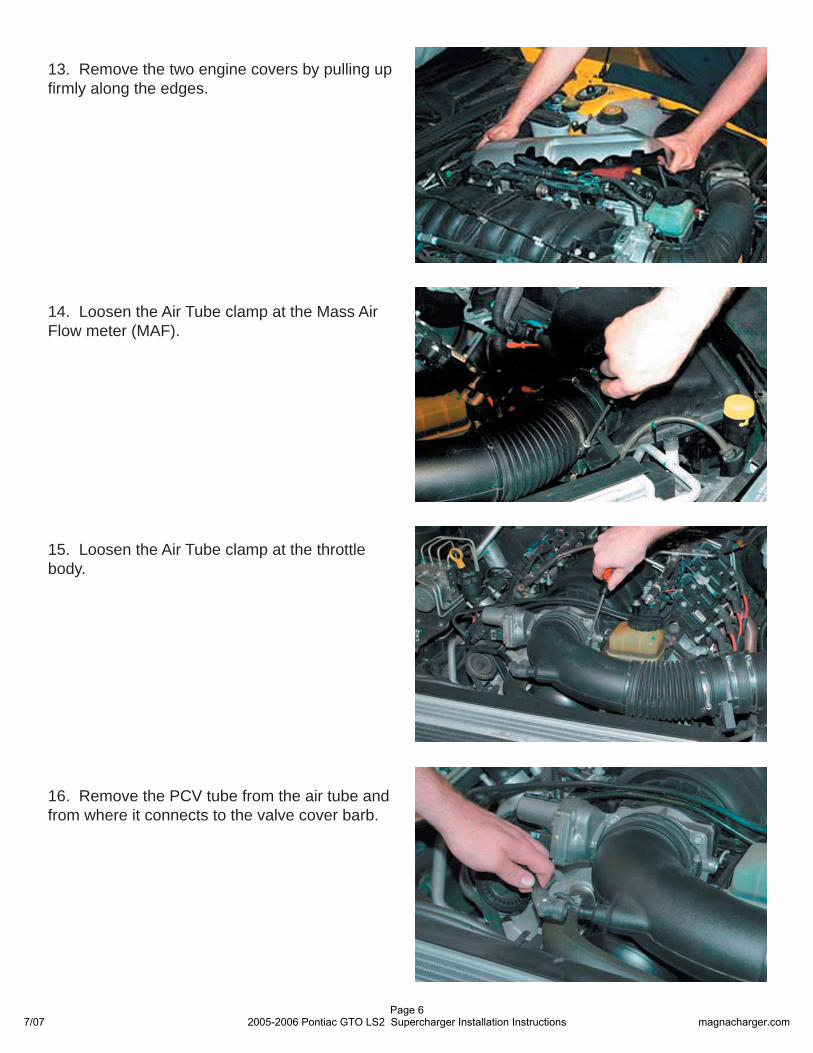
13. Remove the two engine covers by pulling up fi rmly along the edges.
14. Loosen the Air Tube clamp at the Mass Air Flow meter (MAF).
15. Loosen the Air Tube clamp at the throttle body.
16. Remove the PCV tube from the air tube and from where it connects to the valve cover barb.
7/07Page 6
2005-2006 Pontiac GTO LS2 Supercharger Installation Instructions magnacharger.com
19. Remove the PCV hose that connects the intake manifold to the engine valley cover vent.
18. Disconnect the Electronic Throttle Control (ETC) connector on the right side.
17. Remove the air tube completely, it will not be re-used.
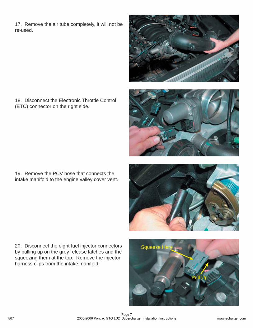
20. Disconnect the eight fuel injector connectors by pulling up on the grey release latches and the squeezing them at the top. Remove the injector harness clips from the intake manifold.
Pull Up
Squeeze Here
7/07Page 7
2005-2006 Pontiac GTO LS2 Supercharger Installation Instructions magnacharger.com
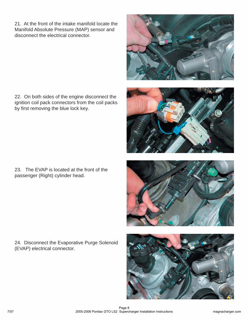
22. On both sides of the engine disconnect the ignition coil pack connectors from the coil packs by fi rst removing the blue lock key.
21. At the front of the intake manifold locate the Manifold Absolute Pressure (MAP) sensor and disconnect the electrical connector.
24. Disconnect the Evaporative Purge Solenoid (EVAP) electrical connector.
23. The EVAP is located at the front of the passenger (Right) cylinder head.
7/07Page 8
2005-2006 Pontiac GTO LS2 Supercharger Installation Instructions magnacharger.com
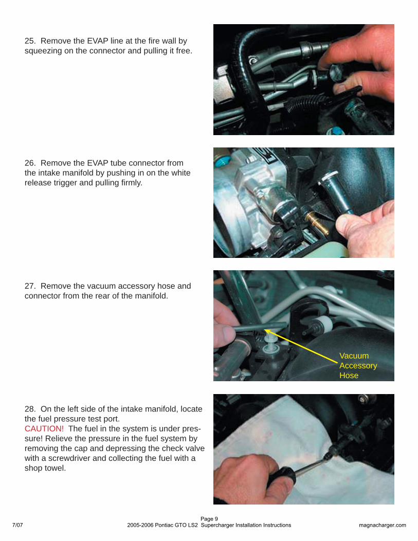
25. Remove the EVAP line at the fi re wall by squeezing on the connector and pulling it free.
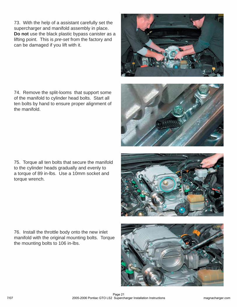
27. Remove the vacuum accessory hose and connector from the rear of the manifold.
28. On the left side of the intake manifold, locate the fuel pressure test port. CAUTION! The fuel in the system is under pres-sure! Relieve the pressure in the fuel system by removing the cap and depressing the check valve with a screwdriver and collecting the fuel with a shop towel.
26. Remove the EVAP tube connector from the intake manifold by pushing in on the white release trigger and pulling fi rmly.
VacuumAccessoryHose
7/07Page 9
2005-2006 Pontiac GTO LS2 Supercharger Installation Instructions magnacharger.com

29. Remove the fuel line from the fuel rail by fi rst prying the lock clip free with a small screwdriver. Use the supplied removal tool to remove the fuel line connector.
30. Remove the intake manifold by loosening the ten manifold bolts with a socket wrench and a 8mm socket.
31. Remove the intake manifold, fuel system and throttle body assembly.
32. Use a shop vacuum cleaner to remove any debris or dirt from the intake port area and engine valley cover.
ManifoldBolts
Tool Lock Clip
7/07Page 10
2005-2006 Pontiac GTO LS2 Supercharger Installation Instructions magnacharger.com
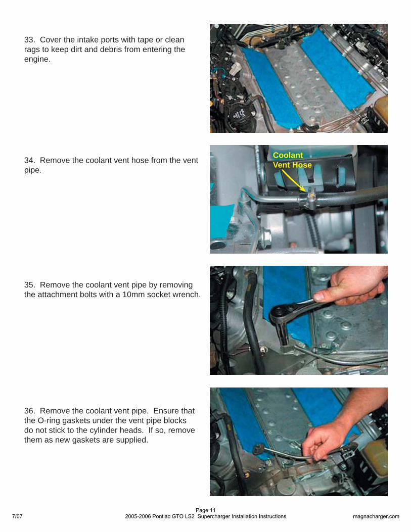
33. Cover the intake ports with tape or clean rags to keep dirt and debris from entering the engine.
36. Remove the coolant vent pipe. Ensure that the O-ring gaskets under the vent pipe blocks do not stick to the cylinder heads. If so, remove them as new gaskets are supplied.
35. Remove the coolant vent pipe by removing the attachment bolts with a 10mm socket wrench.
34. Remove the coolant vent hose from the vent pipe.
Coolant Vent Hose
7/07Page 11
2005-2006 Pontiac GTO LS2 Supercharger Installation Instructions magnacharger.com
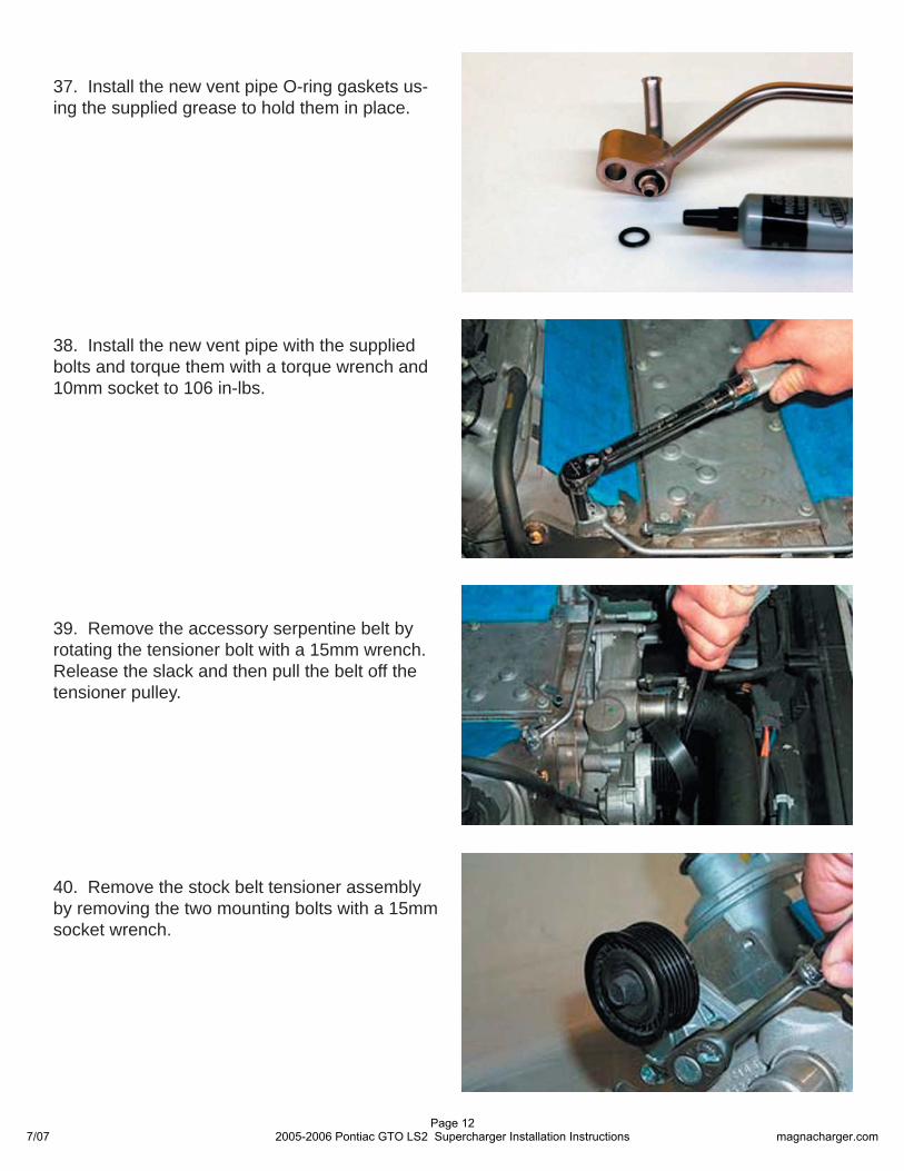
38. Install the new vent pipe with the supplied bolts and torque them with a torque wrench and 10mm socket to 106 in-lbs.
37. Install the new vent pipe O-ring gaskets us-ing the supplied grease to hold them in place.
39. Remove the accessory serpentine belt by rotating the tensioner bolt with a 15mm wrench. Release the slack and then pull the belt off the tensioner pulley.
40. Remove the stock belt tensioner assembly by removing the two mounting bolts with a 15mm socket wrench.
7/07Page 12
2005-2006 Pontiac GTO LS2 Supercharger Installation Instructions magnacharger.com
41. Install the new tensioner assembly in place of the stock unit with the supplied bolts and torque them to 40 ft-lbs.
42. Remove the engine oil pressure sensor con-nector from the pressure sensor located at the rear of the valley cover.
43. Remove the engine oil pressure sensor from the valley cover with a 28mm wrench.
44. Remove the engine valley cover and gas-ket by removing the ten bolts with a ratchet and 13mm socket.
7/07Page 13
2005-2006 Pontiac GTO LS2 Supercharger Installation Instructions magnacharger.com
45. The gasket will be reused, the original val-ley cover and bolts will not. Inspect the gasket for any damage and then reinstall, note that it will only fi t correctly in one position.
46. Using a small straight blade screwdriver, remove the 8 O-rings from the underside of the engine valley cover and transfer them to the grooves in the bottom of the new cover.
47. Install the new engine valley cover and fl at-head bolts supplied with a 5mm Allen socket and torque the bolts to 18 lb-ft. Insert the six O-rings in the recesses in the new valley cover.
48. Install the Oil Pressure Transmitter in the new valley cover with a 26mm socket and torque it to 18 lb-ft.
7/07Page 14
2005-2006 Pontiac GTO LS2 Supercharger Installation Instructions magnacharger.com
49. Re-connect the oil pressure transmitter elec-trical connector.
50. Re-install the oil pressure sensor and torque it to 15 ft-lbs. Re-attach the sensor electrical con-nector.
51. Remove the engine lift bracket from the rear of the right cylinder head by removing its two mounting bolts with a 15mm wrench.
52. The automatic transmission fi ll tube will need to be moved slightly outward to avoid contact with the supercharger fuel cross-over pipe.
7/07Page 15
2005-2006 Pontiac GTO LS2 Supercharger Installation Instructions magnacharger.com
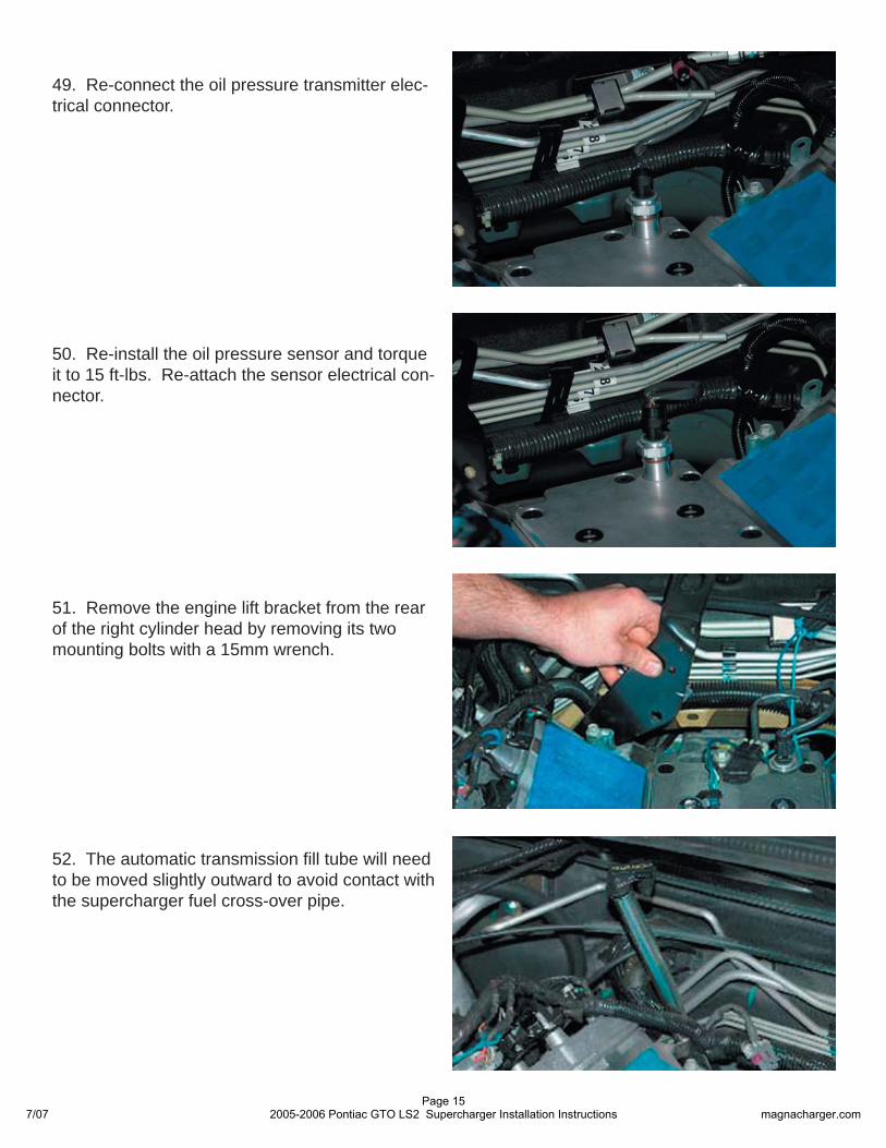
54. Remove the throttle body by removing the four mounting bolts with a 10mm socket wrench.
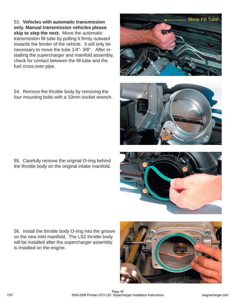
55. Carefully remove the original O-ring behind the throttle body on the original intake manifold.
56. Install the throttle body O-ring into the groove on the new inlet manifold. The LS2 throttle body will be installed after the supercharger assembly is installed on the engine.
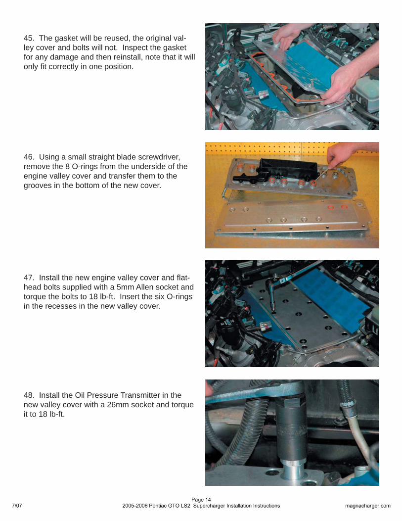
53. Vehicles with automatic transmission only. Manual transmission vehicles please skip to step the next. Move the automatic transmission fi ll tube by pulling it fi rmly outward towards the fender of the vehicle. It will only be necessary to move the tube 1/4”- 3/8”. After in-stalling the supercharger and manifold assembly, check for contact between the fi ll tube and the fuel cross-over pipe.
Move Fill Tube
7/07Page 16
2005-2006 Pontiac GTO LS2 Supercharger Installation Instructions magnacharger.com
57. Remove the MAF from the air box by loosen-ing the connector clamp.
58. Pull back the grey locking latch on the MAF electrical connector and then squeeze the con-nector to remove it.
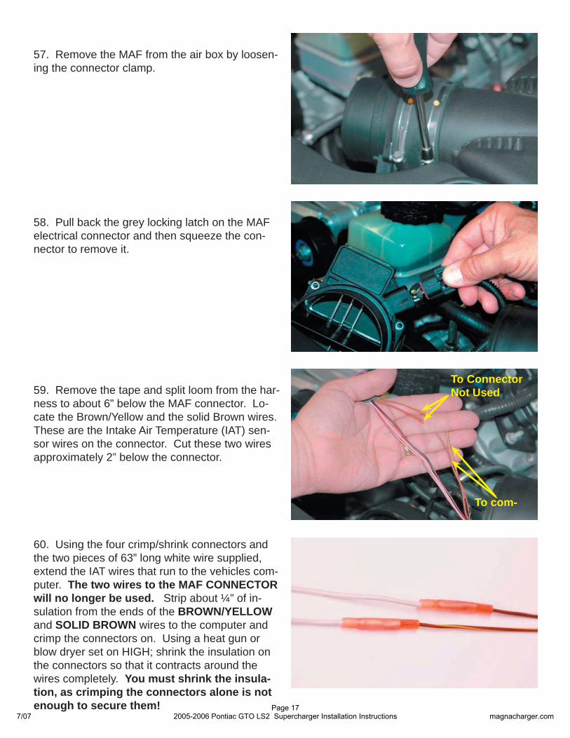
59. Remove the tape and split loom from the har-ness to about 6” below the MAF connector. Lo-cate the Brown/Yellow and the solid Brown wires. These are the Intake Air Temperature (IAT) sen-sor wires on the connector. Cut these two wires approximately 2” below the connector.
To ConnectorNot Used
To com-
60. Using the four crimp/shrink connectors and the two pieces of 63” long white wire supplied, extend the IAT wires that run to the vehicles com-puter. The two wires to the MAF CONNECTOR will no longer be used. Strip about ¼” of in-sulation from the ends of the BROWN/YELLOW and SOLID BROWN wires to the computer and crimp the connectors on. Using a heat gun or blow dryer set on HIGH; shrink the insulation on the connectors so that it contracts around the wires completely. You must shrink the insula-tion, as crimping the connectors alone is not enough to secure them!
7/07Page 17
2005-2006 Pontiac GTO LS2 Supercharger Installation Instructions magnacharger.com
62. When you are fi nished cover the wires and connectors with the piece of split loom supplied.Route the new extended harness with the tie straps supplied along the vehicle harness to the fi re wall and over to the rear of the right (pas-senger) side cylinder head. You will be instructed to connect the harness to a new IAT sensor in a later step. Replace the MAF and tighten its mounting clamp securely. Re-install the MAF electrical connector.
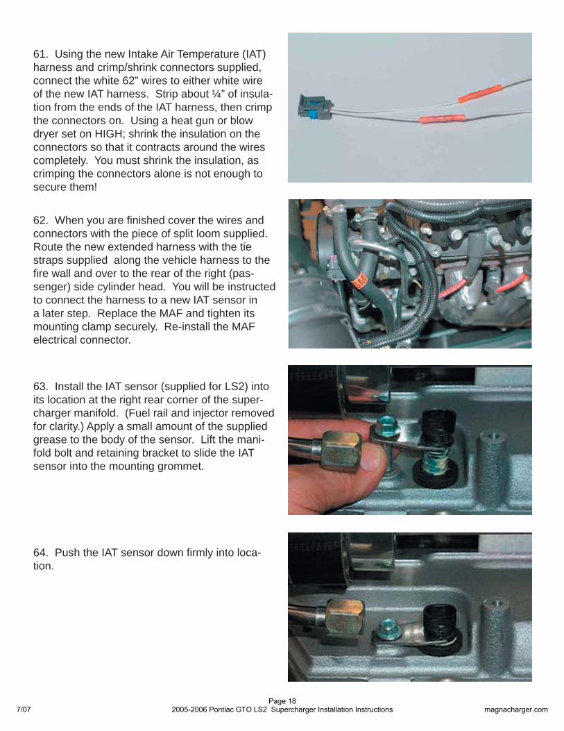
63. Install the IAT sensor (supplied for LS2) into its location at the right rear corner of the super-charger manifold. (Fuel rail and injector removed for clarity.) Apply a small amount of the supplied grease to the body of the sensor. Lift the mani-fold bolt and retaining bracket to slide the IAT sensor into the mounting grommet.
64. Push the IAT sensor down fi rmly into loca-tion.
61. Using the new Intake Air Temperature (IAT) harness and crimp/shrink connectors supplied, connect the white 62” wires to either white wire of the new IAT harness. Strip about ¼” of insula-tion from the ends of the IAT harness, then crimp the connectors on. Using a heat gun or blow dryer set on HIGH; shrink the insulation on the connectors so that it contracts around the wires completely. You must shrink the insulation, as crimping the connectors alone is not enough to secure them!
7/07Page 18
2005-2006 Pontiac GTO LS2 Supercharger Installation Instructions magnacharger.com
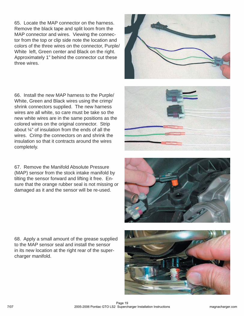
65. Locate the MAP connector on the harness. Remove the black tape and split loom from the MAP connector and wires. Viewing the connec-tor from the top or clip side note the location and colors of the three wires on the connector, Purple/White left, Green center and Black on the right. Approximately 1” behind the connector cut these three wires.
66. Install the new MAP harness to the Purple/White, Green and Black wires using the crimp/shrink connectors supplied. The new harness wires are all white, so care must be take so the new white wires are in the same positions as the colored wires on the original connector. Strip about ¼” of insulation from the ends of all the wires. Crimp the connectors on and shrink the insulation so that it contracts around the wires completely.
67. Remove the Manifold Absolute Pressure (MAP) sensor from the stock intake manifold by tilting the sensor forward and lifting it free. En-sure that the orange rubber seal is not missing or damaged as it and the sensor will be re-used.
68. Apply a small amount of the grease supplied to the MAP sensor seal and install the sensor in its new location at the right rear of the super-charger manifold.
7/07Page 19
2005-2006 Pontiac GTO LS2 Supercharger Installation Instructions magnacharger.com
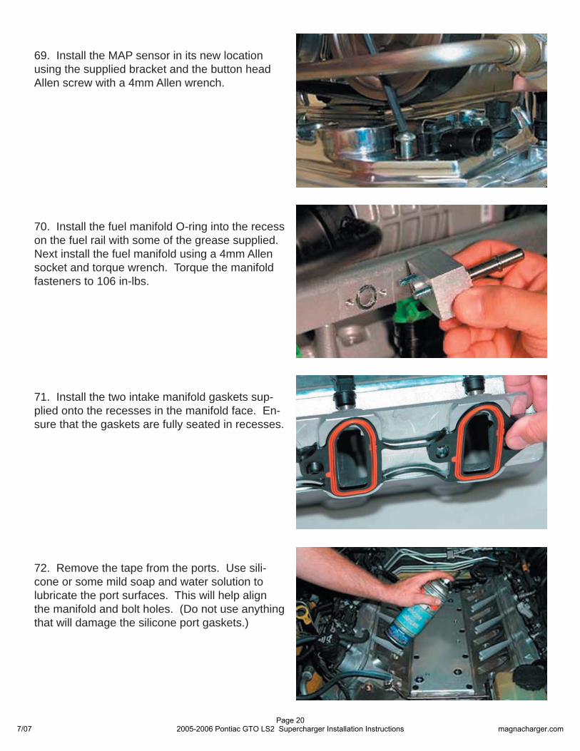
70. Install the fuel manifold O-ring into the recess on the fuel rail with some of the grease supplied. Next install the fuel manifold using a 4mm Allen socket and torque wrench. Torque the manifold fasteners to 106 in-lbs.
71. Install the two intake manifold gaskets sup-plied onto the recesses in the manifold face. En-sure that the gaskets are fully seated in recesses.
72. Remove the tape from the ports. Use sili-cone or some mild soap and water solution to lubricate the port surfaces. This will help align the manifold and bolt holes. (Do not use anything that will damage the silicone port gaskets.)
69. Install the MAP sensor in its new location using the supplied bracket and the button head Allen screw with a 4mm Allen wrench.
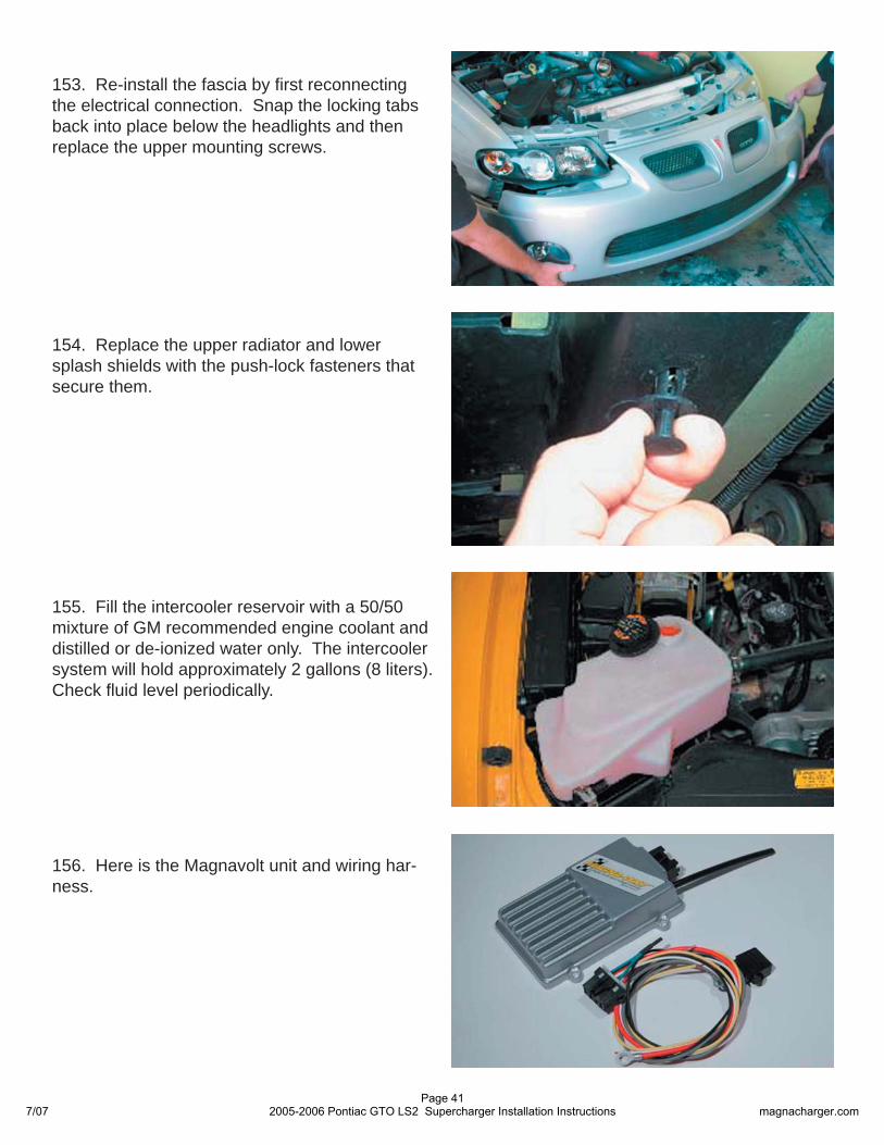
7/07Page 20
2005-2006 Pontiac GTO LS2 Supercharger Installation Instructions magnacharger.com
73. With the help of a assistant carefully set the supercharger and manifold assembly in place. Do not use the black plastic bypass canister as a lifting point. This is pre-set from the factory and can be damaged if you lift with it.
74. Remove the split-looms that support some of the manifold to cylinder head bolts. Start all ten bolts by hand to ensure proper alignment of the manifold.
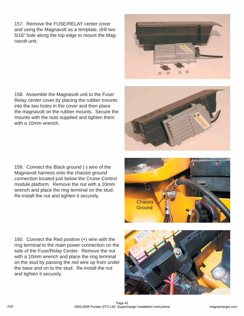
75. Torque all ten bolts that secure the manifold to the cylinder heads gradually and evenly to a torque of 89 in-lbs. Use a 10mm socket and torque wrench.
76. Install the throttle body onto the new inlet manifold with the original mounting bolts. Torque the mounting bolts to 106 in-lbs.
7/07Page 21
2005-2006 Pontiac GTO LS2 Supercharger Installation Instructions magnacharger.com
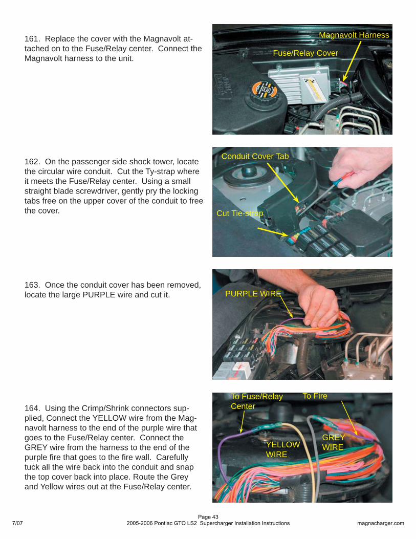
78. Install the coil pack connectors and blue lock keys on both sides of the engine.
79. At the rear of the supercharger on the pas-senger side, plug in the new MAP and IAT con-nections.
80. Install the eight Injector Wiring Adaptors on to the harness fuel injectors connectors.
77. Ensure that there is clearance between the transmission fi ll tube and the fuel cross-over pipe.
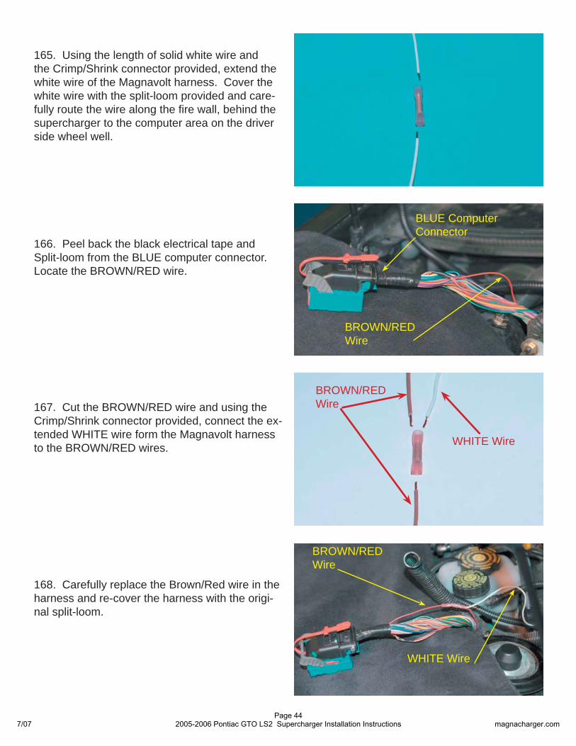
Injector Wiring Adaptor
Note Cut-Away
Clearance Between Fill Tube and Fuel Cross-Over Pipe
7/07Page 22
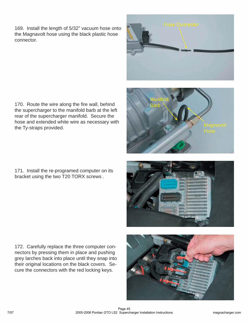
2005-2006 Pontiac GTO LS2 Supercharger Installation Instructions magnacharger.com
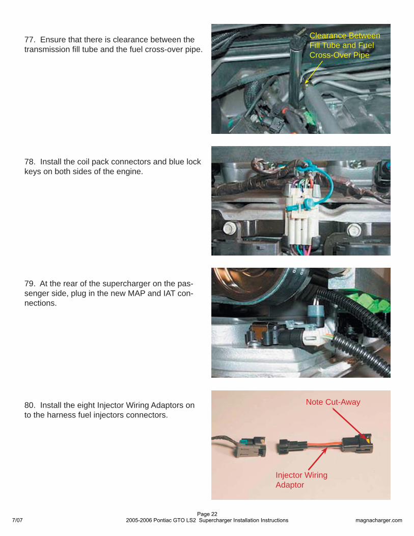
81. Install the Injector Wiring Adaptors on all eight fuel injectors. Note that the cut-away side of the connector goes towards the top of the injector.
Cut-Away
84. Using the piece of 5/16” EVAP hose sup-plied cut it into two pieces. One piece 28” long and the other 16” long. (The hoses are shown shorter for clarity.) Starting with the longer of the two, assemble the hose with the test port on one end and the right angle on the other using the #6 clamps supplied. On the remaining hose, as-semble it with the straight fi tting, squeeze fi tting and clamps.
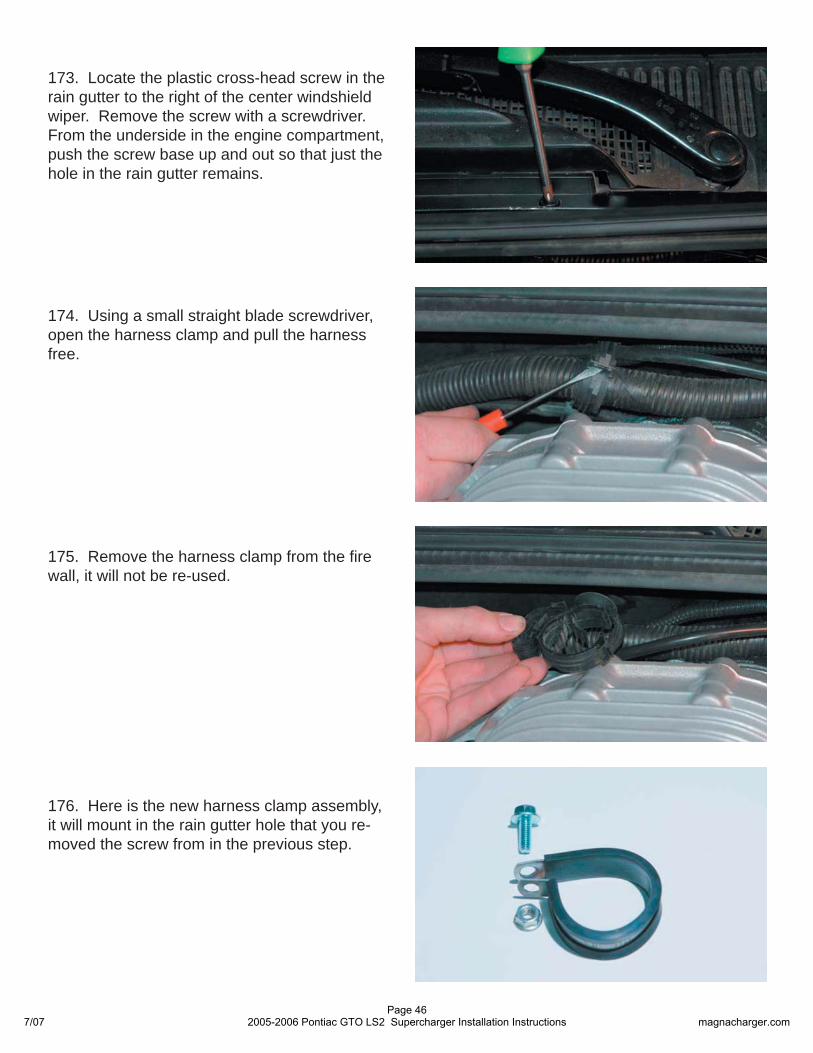
83. Using a sharp shop knife, cut the hard plastic tube where it covers the barbed end of the EVAP fi ttings. Take care not to damage the fi ttings as they will be reused.
82. Locate the two hard plastic EVAP lines previ-ously removed.
Right Angle FittingTest Port Fitting
28” EVAP Hose
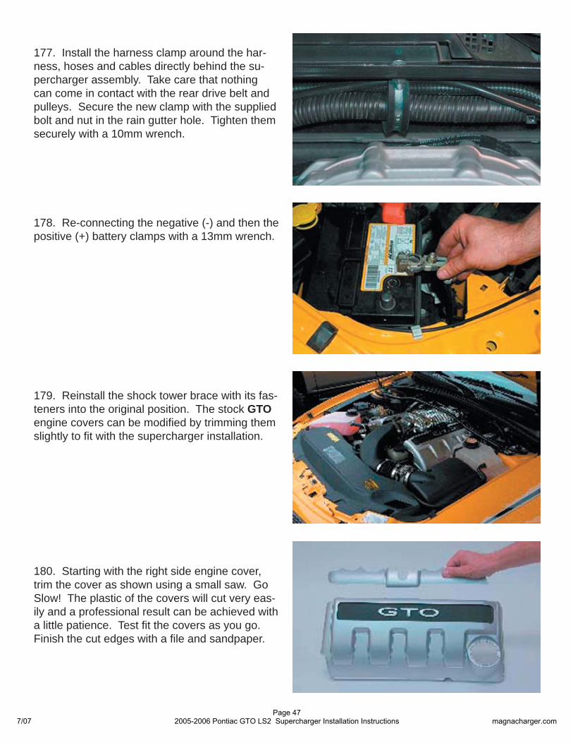
SqueezeFitting
# 6 Clamps
16” EVAP HoseStraight Fitting
7/07Page 23
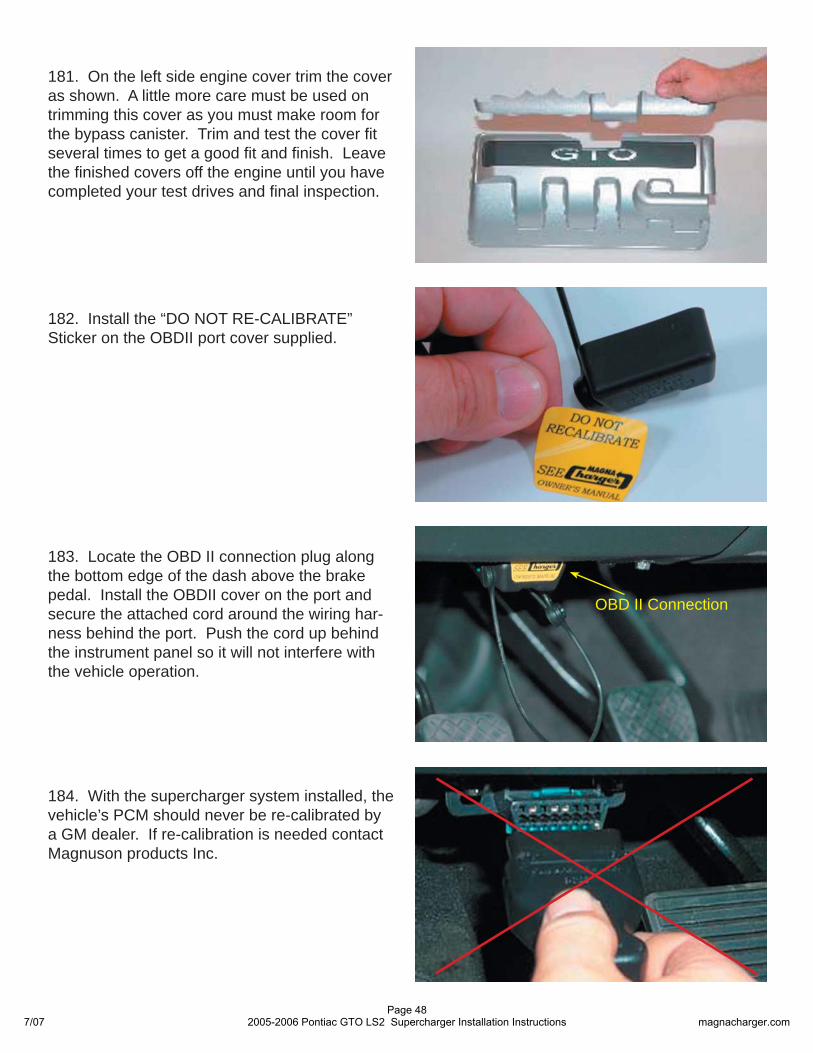
2005-2006 Pontiac GTO LS2 Supercharger Installation Instructions magnacharger.com
86. Re-connect the Purge solenoid electrical connection, then install the right angle fi tting of the long EVAP hose to the top connection of the Purge solenoid. Connect the squeeze fi tting of the shorter EVAP hose to the lower connection of the solenoid.
87. Connect the remaining end of the short EVAP hose to the fi tting on the passenger (left) side of the inlet manifold above the supercharger drive shaft.
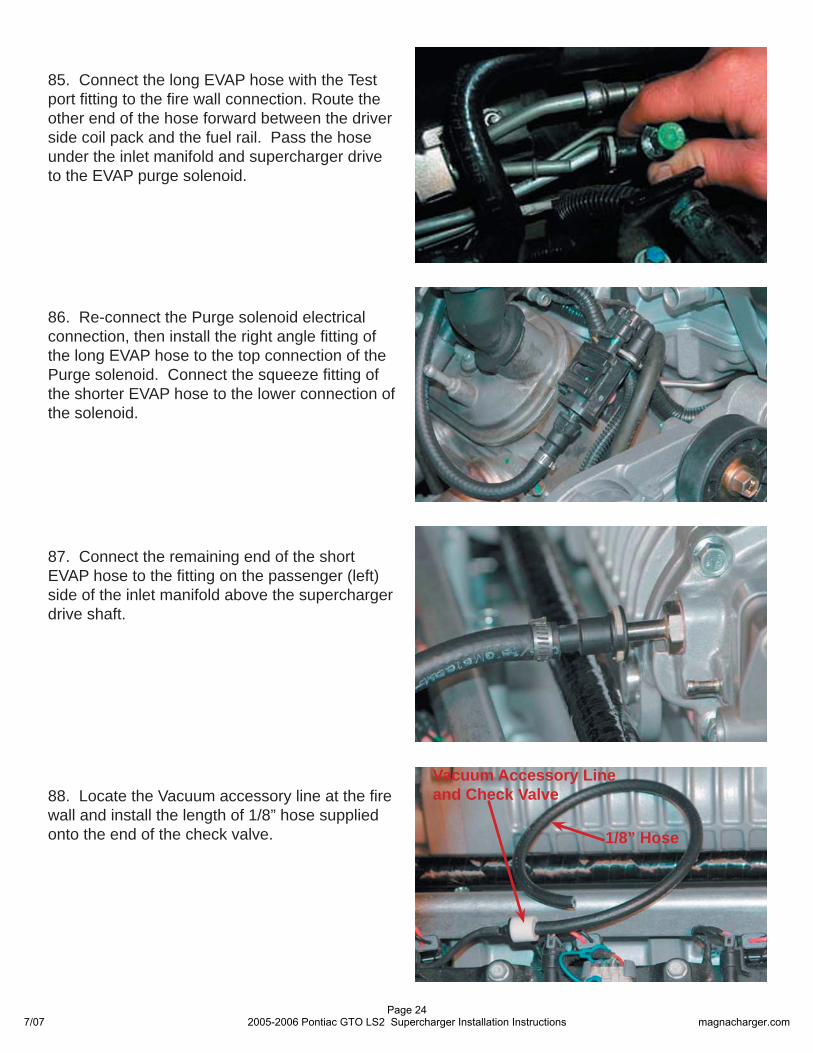
88. Locate the Vacuum accessory line at the fi re wall and install the length of 1/8” hose supplied onto the end of the check valve.
Vacuum Accessory Lineand Check Valve
1/8” Hose
85. Connect the long EVAP hose with the Test port fi tting to the fi re wall connection. Route the other end of the hose forward between the driver side coil pack and the fuel rail. Pass the hose under the inlet manifold and supercharger drive to the EVAP purge solenoid.
7/07Page 24
2005-2006 Pontiac GTO LS2 Supercharger Installation Instructions magnacharger.com
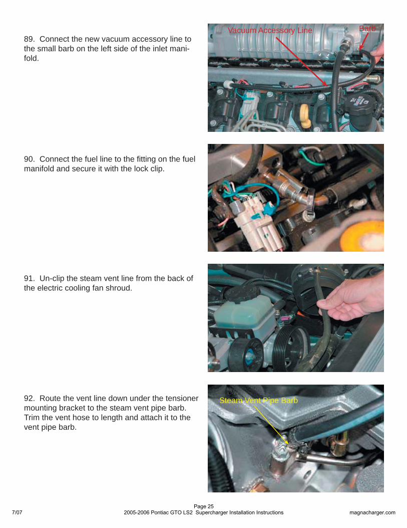
89. Connect the new vacuum accessory line to the small barb on the left side of the inlet mani-fold.
Vacuum Accessory Line Barb
90. Connect the fuel line to the fi tting on the fuel manifold and secure it with the lock clip.
91. Un-clip the steam vent line from the back of the electric cooling fan shroud.
92. Route the vent line down under the tensioner mounting bracket to the steam vent pipe barb. Trim the vent hose to length and attach it to the vent pipe barb.
Steam Vent Pipe Barb
7/07Page 25
2005-2006 Pontiac GTO LS2 Supercharger Installation Instructions magnacharger.com
95. Cover the extended ETC harness with the new split loom supplied. Route the extended har-ness under the throttle body and install the con-nector onto the throttle body
94. Using the color coded lengths of wire and crimp/shrink connectors supplied, extend the six throttle body connector wires. Be sure to correct-ly match the extension wire color to the harness and at the throttle body connector. Strip about ¼” of insulation from the ends of all the wires. Crimp the connectors on and shrink the insulation so that it contracts around the wires completely.
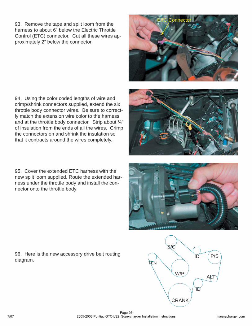
96. Here is the new accessory drive belt routing diagram.
S/C
W/P
CRANK
TENID
ID
93. Remove the tape and split loom from the harness to about 6” below the Electric Throttle Control (ETC) connector. Cut all these wires ap-proximately 2” below the connector.
ETC Connector
ALT
P/S
7/07Page 26
2005-2006 Pontiac GTO LS2 Supercharger Installation Instructions magnacharger.com
97. Using a long 15mm wrench to compress the tensioner, install the new belt using the diagram above.
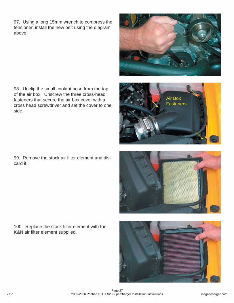
98. Unclip the small coolant hose from the top of the air box. Unscrew the three cross-head fasteners that secure the air box cover with a cross head screwdriver and set the cover to one side.
Air BoxFasteners
100. Replace the stock fi lter element with the K&N air fi lter element supplied.
99. Remove the stock air fi lter element and dis-card it.
7/07Page 27
2005-2006 Pontiac GTO LS2 Supercharger Installation Instructions magnacharger.com
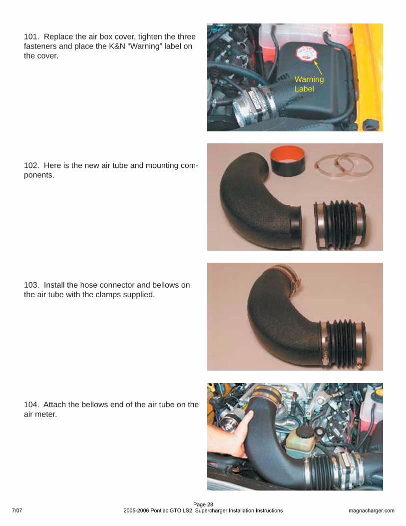
102. Here is the new air tube and mounting com-ponents.
104. Attach the bellows end of the air tube on the air meter.
103. Install the hose connector and bellows on the air tube with the clamps supplied.
101. Replace the air box cover, tighten the three fasteners and place the K&N “Warning” label on the cover.
Warning Label
7/07Page 28
2005-2006 Pontiac GTO LS2 Supercharger Installation Instructions magnacharger.com
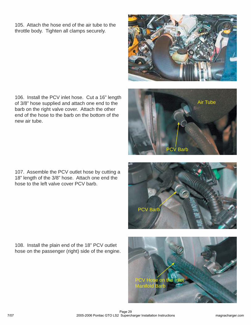
105. Attach the hose end of the air tube to the throttle body. Tighten all clamps securely.
106. Install the PCV inlet hose. Cut a 16” length of 3/8” hose supplied and attach one end to the barb on the right valve cover. Attach the other end of the hose to the barb on the bottom of the new air tube.
107. Assemble the PCV outlet hose by cutting a 18” length of the 3/8” hose. Attach one end the hose to the left valve cover PCV barb.
108. Install the plain end of the 18” PCV outlet hose on the passenger (right) side of the engine.
PCV Hose on the Inlet Manifold Barb
Air Tube
PCV Barb
PCV Barb
7/07Page 29
2005-2006 Pontiac GTO LS2 Supercharger Installation Instructions magnacharger.com
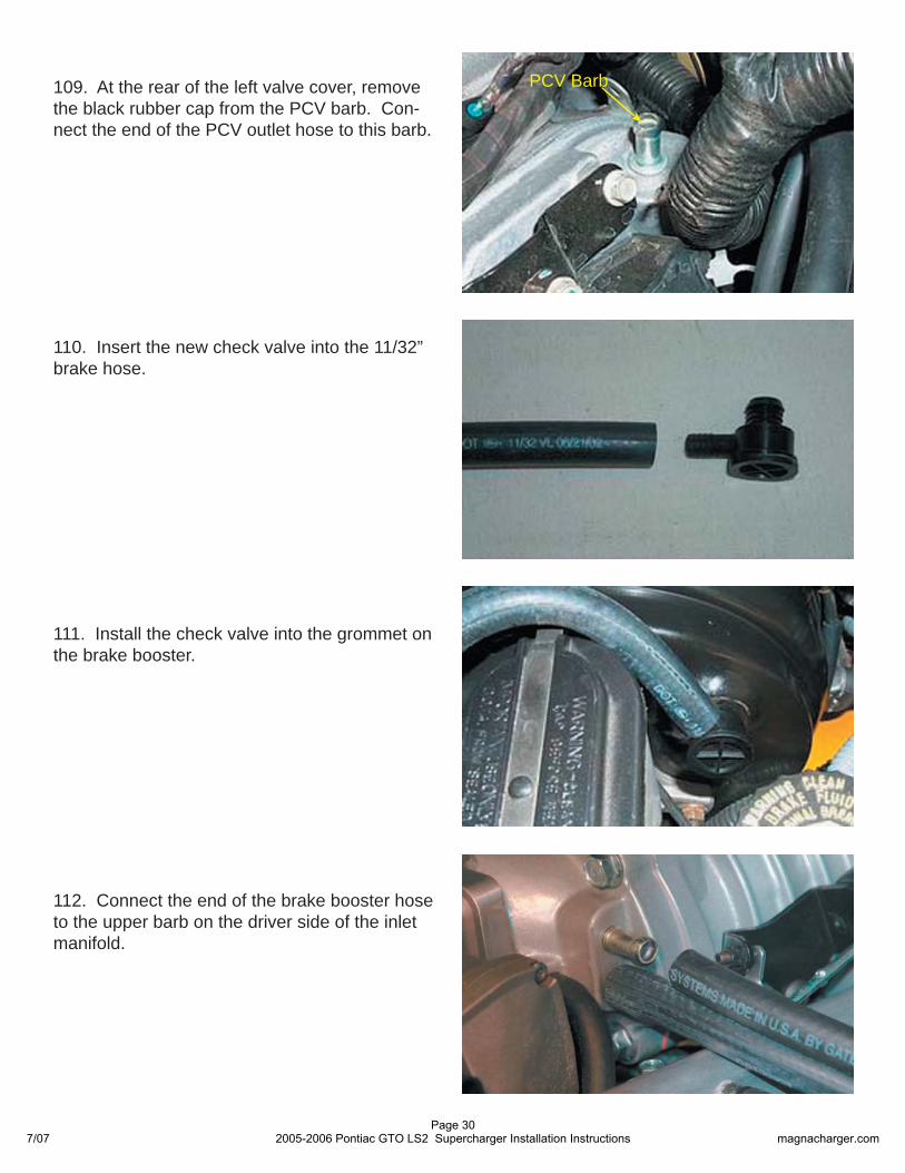
109. At the rear of the left valve cover, remove the black rubber cap from the PCV barb. Con-nect the end of the PCV outlet hose to this barb.
PCV Barb
110. Insert the new check valve into the 11/32” brake hose.
111. Install the check valve into the grommet on the brake booster.
112. Connect the end of the brake booster hose to the upper barb on the driver side of the inlet manifold.
7/07Page 30
2005-2006 Pontiac GTO LS2 Supercharger Installation Instructions magnacharger.com
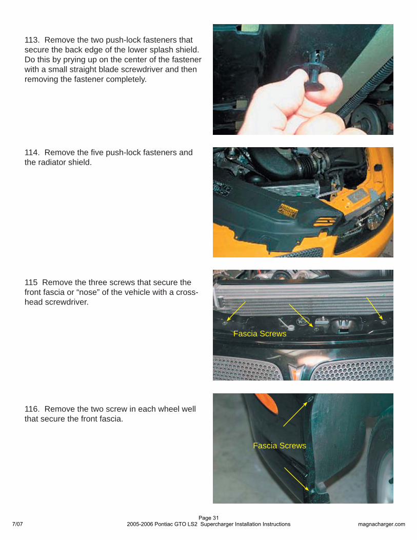
113. Remove the two push-lock fasteners that secure the back edge of the lower splash shield. Do this by prying up on the center of the fastener with a small straight blade screwdriver and then removing the fastener completely.
114. Remove the fi ve push-lock fasteners and the radiator shield.
Fascia Screws
Fascia Screws
116. Remove the two screw in each wheel well that secure the front fascia.
115 Remove the three screws that secure the front fascia or “nose” of the vehicle with a cross-head screwdriver.
7/07Page 31
2005-2006 Pontiac GTO LS2 Supercharger Installation Instructions magnacharger.com
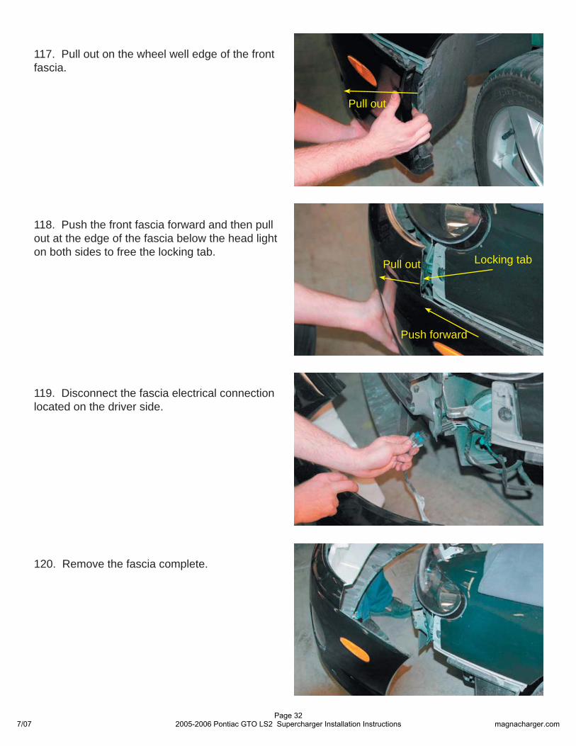
118. Push the front fascia forward and then pull out at the edge of the fascia below the head light on both sides to free the locking tab.
117. Pull out on the wheel well edge of the front fascia.
119. Disconnect the fascia electrical connection located on the driver side.
120. Remove the fascia complete.
Pull out
Pull out
Push forward
Locking tab
7/07Page 32
2005-2006 Pontiac GTO LS2 Supercharger Installation Instructions magnacharger.com
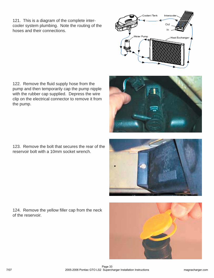
121. This is a diagram of the complete inter-cooler system plumbing. Note the routing of the hoses and their connections.
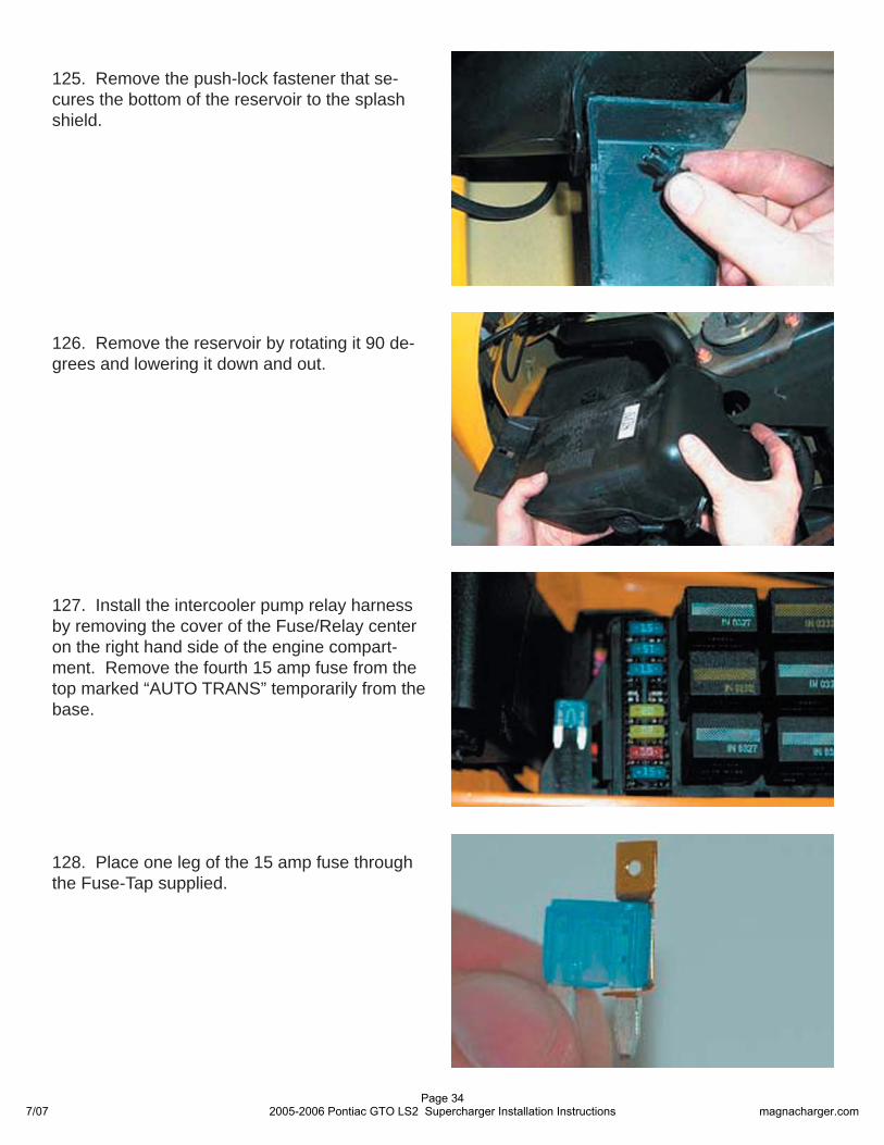
124. Remove the yellow fi ller cap from the neck of the reservoir.
122. Remove the fl uid supply hose from the pump and then temporarily cap the pump nipple with the rubber cap supplied. Depress the wire clip on the electrical connector to remove it from the pump.
123. Remove the bolt that secures the rear of the reservoir bolt with a 10mm socket wrench.
Out
In
7/07Page 33
2005-2006 Pontiac GTO LS2 Supercharger Installation Instructions magnacharger.com
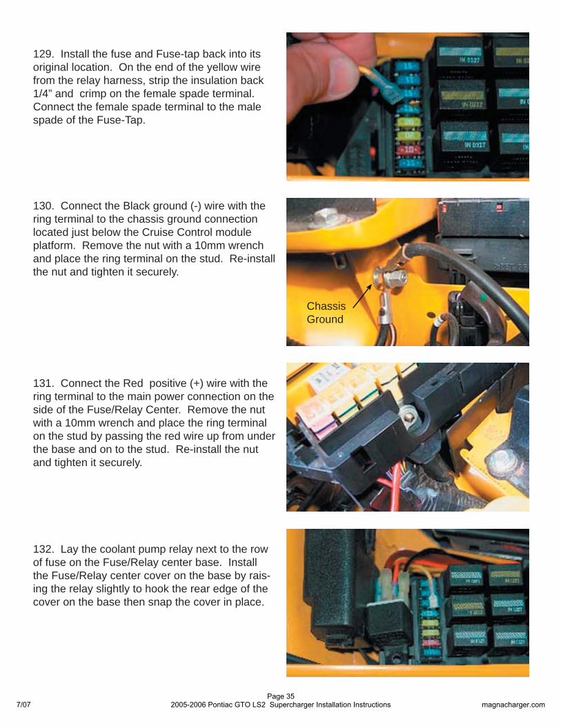
126. Remove the reservoir by rotating it 90 de-grees and lowering it down and out.
127. Install the intercooler pump relay harness by removing the cover of the Fuse/Relay center on the right hand side of the engine compart-ment. Remove the fourth 15 amp fuse from the top marked “AUTO TRANS” temporarily from the base.
128. Place one leg of the 15 amp fuse through the Fuse-Tap supplied.
125. Remove the push-lock fastener that se-cures the bottom of the reservoir to the splash shield.
7/07Page 34
2005-2006 Pontiac GTO LS2 Supercharger Installation Instructions magnacharger.com
130. Connect the Black ground (-) wire with the ring terminal to the chassis ground connection located just below the Cruise Control module platform. Remove the nut with a 10mm wrench and place the ring terminal on the stud. Re-install the nut and tighten it securely.
129. Install the fuse and Fuse-tap back into its original location. On the end of the yellow wire from the relay harness, strip the insulation back 1/4” and crimp on the female spade terminal. Connect the female spade terminal to the male spade of the Fuse-Tap.
ChassisGround
131. Connect the Red positive (+) wire with the ring terminal to the main power connection on the side of the Fuse/Relay Center. Remove the nut with a 10mm wrench and place the ring terminal on the stud by passing the red wire up from under the base and on to the stud. Re-install the nut and tighten it securely.
132. Lay the coolant pump relay next to the row of fuse on the Fuse/Relay center base. Install the Fuse/Relay center cover on the base by rais-ing the relay slightly to hook the rear edge of the cover on the base then snap the cover in place.
7/07Page 35
2005-2006 Pontiac GTO LS2 Supercharger Installation Instructions magnacharger.com
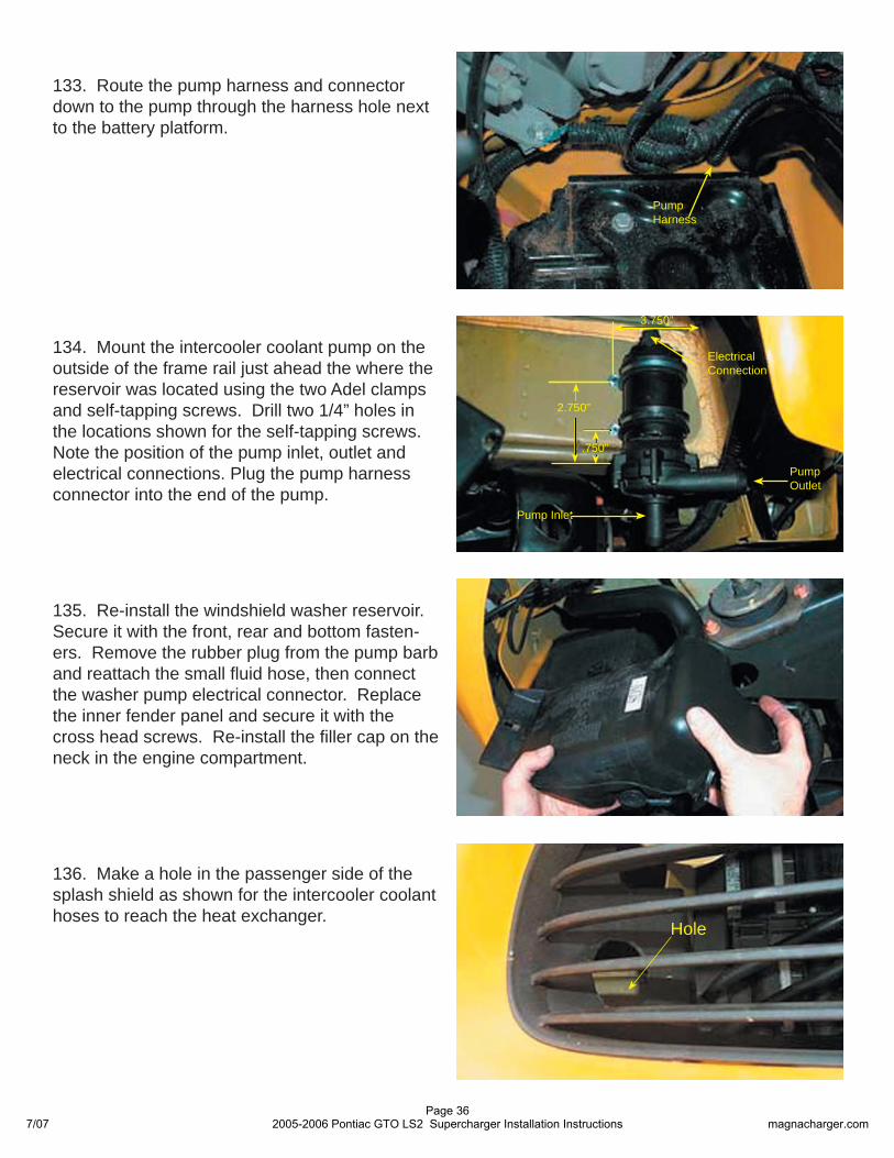
134. Mount the intercooler coolant pump on the outside of the frame rail just ahead the where the reservoir was located using the two Adel clamps and self-tapping screws. Drill two 1/4” holes in the locations shown for the self-tapping screws. Note the position of the pump inlet, outlet and electrical connections. Plug the pump harness connector into the end of the pump.
2.750”
.750”
3.750”
PumpOutlet
Pump Inlet
Electrical Connection
135. Re-install the windshield washer reservoir. Secure it with the front, rear and bottom fasten-ers. Remove the rubber plug from the pump barb and reattach the small fl uid hose, then connect the washer pump electrical connector. Replace the inner fender panel and secure it with the cross head screws. Re-install the fi ller cap on the neck in the engine compartment.
136. Make a hole in the passenger side of the splash shield as shown for the intercooler coolant hoses to reach the heat exchanger.
Hole
133. Route the pump harness and connector down to the pump through the harness hole next to the battery platform.
Pump Harness
7/07Page 36
2005-2006 Pontiac GTO LS2 Supercharger Installation Instructions magnacharger.com
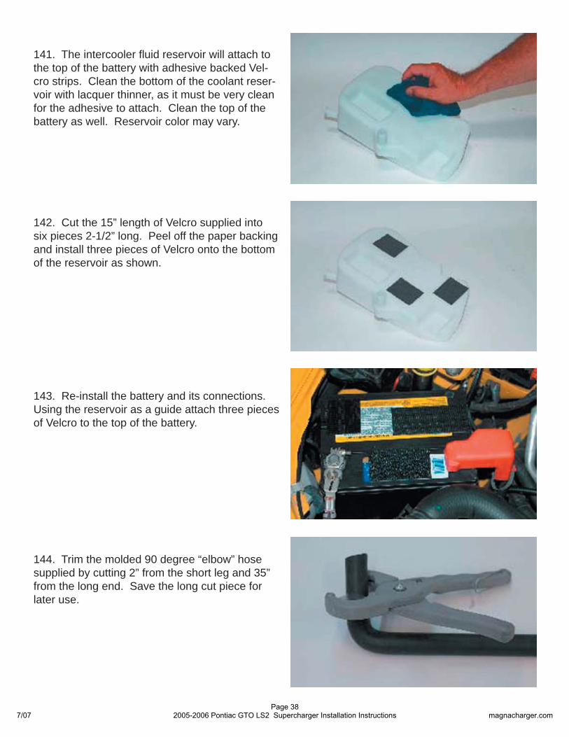
138. Assemble the heat exchanger by peeling the backing paper off the two short plastic strips and apply them to the inside of the upper mounts.
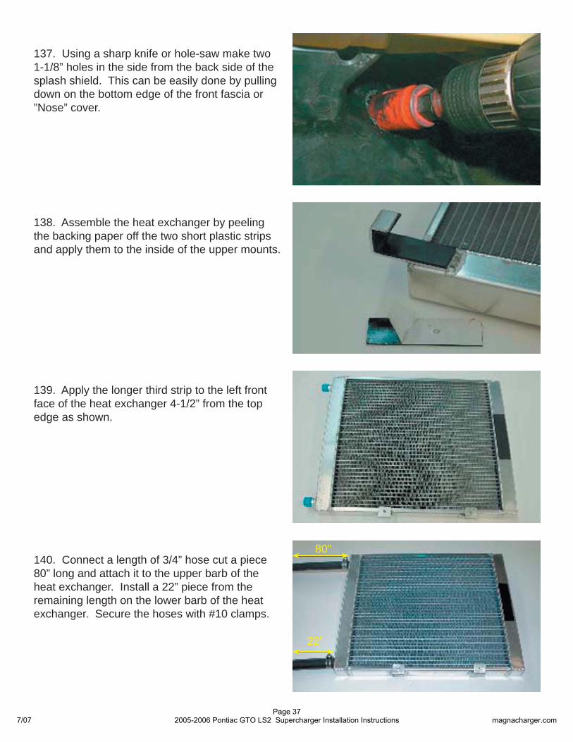
137. Using a sharp knife or hole-saw make two 1-1/8” holes in the side from the back side of the splash shield. This can be easily done by pulling down on the bottom edge of the front fascia or ”Nose” cover.
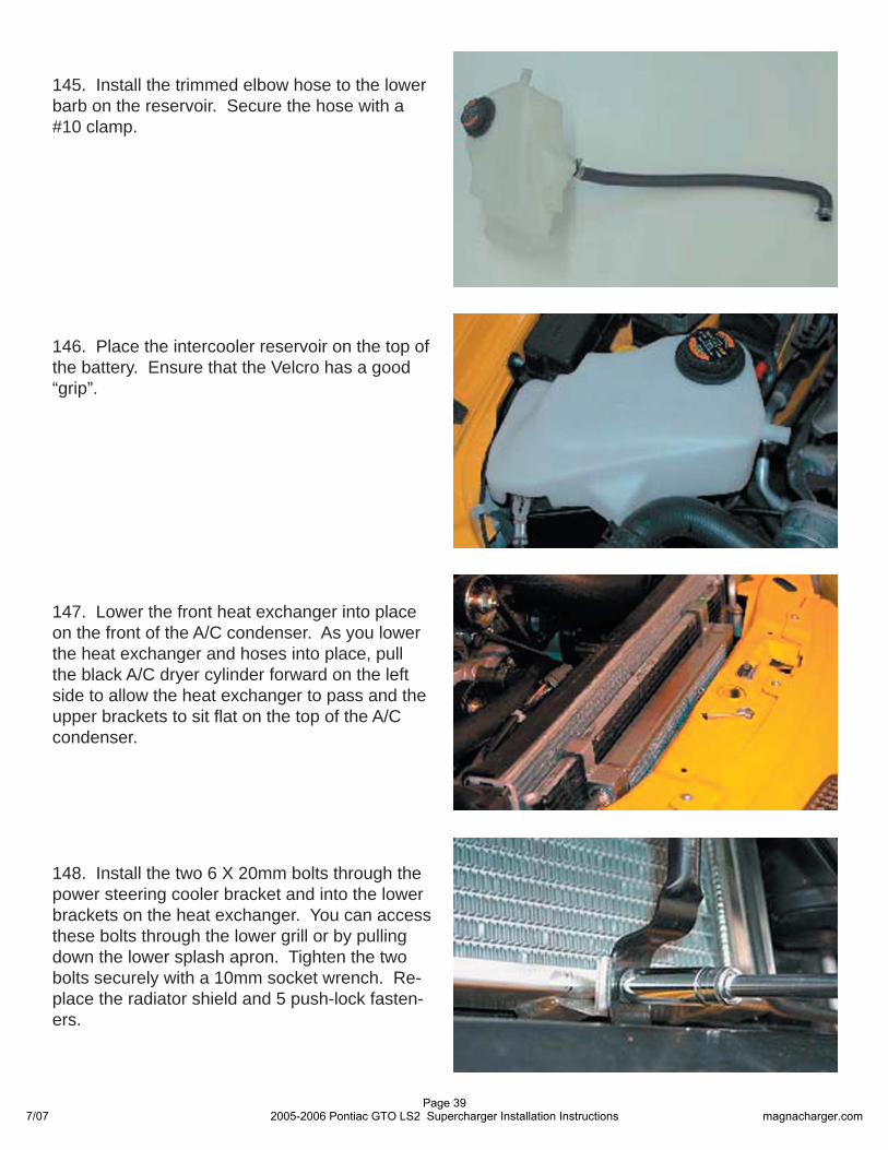
139. Apply the longer third strip to the left front face of the heat exchanger 4-1/2” from the top edge as shown.
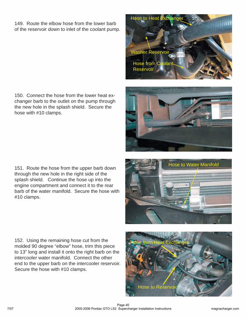
140. Connect a length of 3/4” hose cut a piece 80” long and attach it to the upper barb of the heat exchanger. Install a 22” piece from the remaining length on the lower barb of the heat exchanger. Secure the hoses with #10 clamps.
22”
80”
7/07Page 37
2005-2006 Pontiac GTO LS2 Supercharger Installation Instructions magnacharger.com
142. Cut the 15” length of Velcro supplied into six pieces 2-1/2” long. Peel off the paper backing and install three pieces of Velcro onto the bottom of the reservoir as shown.
143. Re-install the battery and its connections. Using the reservoir as a guide attach three pieces of Velcro to the top of the battery.
144. Trim the molded 90 degree “elbow” hose supplied by cutting 2” from the short leg and 35” from the long end. Save the long cut piece for later use.
141. The intercooler fl uid reservoir will attach to the top of the battery with adhesive backed Vel-cro strips. Clean the bottom of the coolant reser-voir with lacquer thinner, as it must be very clean for the adhesive to attach. Clean the top of the battery as well. Reservoir color may vary.
7/07Page 38
2005-2006 Pontiac GTO LS2 Supercharger Installation Instructions magnacharger.com
146. Place the intercooler reservoir on the top of the battery. Ensure that the Velcro has a good “grip”.
145. Install the trimmed elbow hose to the lower barb on the reservoir. Secure the hose with a #10 clamp.
148. Install the two 6 X 20mm bolts through the power steering cooler bracket and into the lower brackets on the heat exchanger. You can access these bolts through the lower grill or by pulling down the lower splash apron. Tighten the two bolts securely with a 10mm socket wrench. Re-place the radiator shield and 5 push-lock fasten-ers.
147. Lower the front heat exchanger into place on the front of the A/C condenser. As you lower the heat exchanger and hoses into place, pull the black A/C dryer cylinder forward on the left side to allow the heat exchanger to pass and the upper brackets to sit fl at on the top of the A/C condenser.
7/07Page 39
2005-2006 Pontiac GTO LS2 Supercharger Installation Instructions magnacharger.com
149. Route the elbow hose from the lower barb of the reservoir down to inlet of the coolant pump.
Hose to Heat Exchanger
Hose from Coolant Reservoir
Washer Reservoir
150. Connect the hose from the lower heat ex-changer barb to the outlet on the pump through the new hole in the splash shield. Secure the hose with #10 clamps.
152. Using the remaining hose cut from the molded 90 degree “elbow” hose, trim this piece to 13” long and install it onto the right barb on the intercooler water manifold. Connect the other end to the upper barb on the intercooler reservoir. Secure the hose with #10 clamps.
151. Route the hose from the upper barb down through the new hole in the right side of the splash shield. Continue the hose up into the engine compartment and connect it to the rear barb of the water manifold. Secure the hose with #10 clamps.
Hose to Water Manifold
Hose from Heat Exchanger
Hose to Reservoir
7/07Page 40
2005-2006 Pontiac GTO LS2 Supercharger Installation Instructions magnacharger.com
154. Replace the upper radiator and lower splash shields with the push-lock fasteners that secure them.
156. Here is the Magnavolt unit and wiring har-ness.
153. Re-install the fascia by fi rst reconnecting the electrical connection. Snap the locking tabs back into place below the headlights and then replace the upper mounting screws.
155. Fill the intercooler reservoir with a 50/50 mixture of GM recommended engine coolant and distilled or de-ionized water only. The intercooler system will hold approximately 2 gallons (8 liters). Check fl uid level periodically.
7/07Page 41
2005-2006 Pontiac GTO LS2 Supercharger Installation Instructions magnacharger.com
157. Remove the FUSE/RELAY center cover and using the Magnavolt as a template, drill two 5/16” hole along the top edge to mount the Mag-navolt unit.
158. Assemble the Magnavolt unit to the Fuse/Relay center cover by placing the rubber mounts into the two holes in the cover and then place the magnavolt on the rubber mounts. Secure the mounts with the nuts supplied and tighten them with a 10mm wrench.
159. Connect the Black ground (-) wire of the Magnavolt harness onto the chassis ground connection located just below the Cruise Control module platform. Remove the nut with a 10mm wrench and place the ring terminal on the stud. Re-install the nut and tighten it securely.
ChassisGround
160. Connect the Red positive (+) wire with the ring terminal to the main power connection on the side of the Fuse/Relay Center. Remove the nut with a 10mm wrench and place the ring terminal on the stud by passing the red wire up from under the base and on to the stud. Re-install the nut and tighten it securely.
7/07Page 42
2005-2006 Pontiac GTO LS2 Supercharger Installation Instructions magnacharger.com
162. On the passenger side shock tower, locate the circular wire conduit. Cut the Ty-strap where it meets the Fuse/Relay center. Using a small straight blade screwdriver, gently pry the locking tabs free on the upper cover of the conduit to free the cover.
Conduit Cover Tab
Cut Tie-strap
163. Once the conduit cover has been removed, locate the large PURPLE wire and cut it.
164. Using the Crimp/Shrink connectors sup-plied, Connect the YELLOW wire from the Mag-navolt harness to the end of the purple wire that goes to the Fuse/Relay center. Connect the GREY wire from the harness to the end of the purple fi re that goes to the fi re wall. Carefully tuck all the wire back into the conduit and snap the top cover back into place. Route the Grey and Yellow wires out at the Fuse/Relay center.
To Fuse/RelayCenter
To Fire
GREY WIREYELLOW
WIRE
PURPLE WIRE
161. Replace the cover with the Magnavolt at-tached on to the Fuse/Relay center. Connect the Magnavolt harness to the unit. Fuse/Relay Cover
Magnavolt Harness
7/07Page 43
2005-2006 Pontiac GTO LS2 Supercharger Installation Instructions magnacharger.com
167. Cut the BROWN/RED wire and using the Crimp/Shrink connector provided, connect the ex-tended WHITE wire form the Magnavolt harness to the BROWN/RED wires.
168. Carefully replace the Brown/Red wire in the harness and re-cover the harness with the origi-nal split-loom.
BROWN/RED Wire
WHITE Wire
166. Peel back the black electrical tape and Split-loom from the BLUE computer connector. Locate the BROWN/RED wire.
BROWN/RED Wire
BLUE Computer Connector
BROWN/RED Wire
WHITE Wire
165. Using the length of solid white wire and the Crimp/Shrink connector provided, extend the white wire of the Magnavolt harness. Cover the white wire with the split-loom provided and care-fully route the wire along the fi re wall, behind the supercharger to the computer area on the driver side wheel well.
7/07Page 44
2005-2006 Pontiac GTO LS2 Supercharger Installation Instructions magnacharger.com
170. Route the wire along the fi re wall, behind the supercharger to the manifold barb at the left rear of the supercharger manifold. Secure the hose and extended white wire as necessary with the Ty-straps provided.
ManifoldBarb
171. Install the re-programed computer on its bracket using the two T20 TORX screws .
172. Carefully replace the three computer con-nectors by pressing them in place and pushing grey larches back into place until they snap into their original locations on the black covers. Se-cure the connectors with the red locking keys.
169. Install the length of 5/32” vacuum hose onto the Magnavolt hose using the black plastic hose connector.
Hose Connector
MagnavoltHose
7/07Page 45
2005-2006 Pontiac GTO LS2 Supercharger Installation Instructions magnacharger.com
173. Locate the plastic cross-head screw in the rain gutter to the right of the center windshield wiper. Remove the screw with a screwdriver. From the underside in the engine compartment, push the screw base up and out so that just the hole in the rain gutter remains.
174. Using a small straight blade screwdriver, open the harness clamp and pull the harness free.
175. Remove the harness clamp from the fi re wall, it will not be re-used.
176. Here is the new harness clamp assembly, it will mount in the rain gutter hole that you re-moved the screw from in the previous step.
7/07Page 46
2005-2006 Pontiac GTO LS2 Supercharger Installation Instructions magnacharger.com
179. Reinstall the shock tower brace with its fas-teners into the original position. The stock GTO engine covers can be modifi ed by trimming them slightly to fi t with the supercharger installation.
180. Starting with the right side engine cover, trim the cover as shown using a small saw. Go Slow! The plastic of the covers will cut very eas-ily and a professional result can be achieved with a little patience. Test fi t the covers as you go. Finish the cut edges with a fi le and sandpaper.
177. Install the harness clamp around the har-ness, hoses and cables directly behind the su-percharger assembly. Take care that nothing can come in contact with the rear drive belt and pulleys. Secure the new clamp with the supplied bolt and nut in the rain gutter hole. Tighten them securely with a 10mm wrench.
178. Re-connecting the negative (-) and then the positive (+) battery clamps with a 13mm wrench.
7/07Page 47
2005-2006 Pontiac GTO LS2 Supercharger Installation Instructions magnacharger.com
181. On the left side engine cover trim the cover as shown. A little more care must be used on trimming this cover as you must make room for the bypass canister. Trim and test the cover fi t several times to get a good fi t and fi nish. Leave the fi nished covers off the engine until you have completed your test drives and fi nal inspection.
184. With the supercharger system installed, the vehicle’s PCM should never be re-calibrated by a GM dealer. If re-calibration is needed contact Magnuson products Inc.
183. Locate the OBD II connection plug along the bottom edge of the dash above the brake pedal. Install the OBDII cover on the port and secure the attached cord around the wiring har-ness behind the port. Push the cord up behind the instrument panel so it will not interfere with the vehicle operation.
OBD II Connection
182. Install the “DO NOT RE-CALIBRATE” Sticker on the OBDII port cover supplied.
7/07Page 48
2005-2006 Pontiac GTO LS2 Supercharger Installation Instructions magnacharger.com
If you have questions about your vehicles perfor-mance, please check with your installation facility or call Magna Charger at (805) 289-0044, Mon-day through Friday, 8am to 5pm.
Please enjoy your “Magna Charged”performance responsibly.
186. After the initial test drive gradually work the vehicle to wide open throttle runs, listen for any engine detonation (pinging). If engine detonation is present let up on the throttle immediately. Most detonation is caused by low octane gasoline still in the tank.
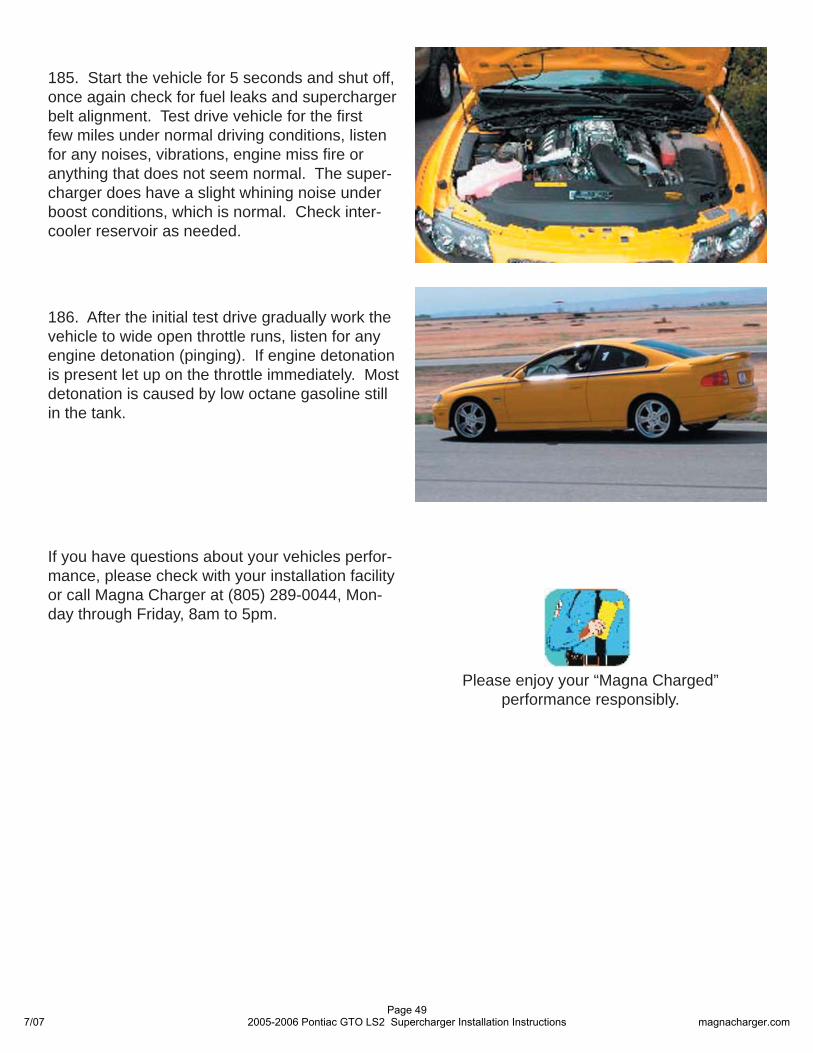
185. Start the vehicle for 5 seconds and shut off, once again check for fuel leaks and supercharger belt alignment. Test drive vehicle for the fi rst few miles under normal driving conditions, listen for any noises, vibrations, engine miss fi re or anything that does not seem normal. The super-charger does have a slight whining noise under boost conditions, which is normal. Check inter-cooler reservoir as needed.
7/07Page 49
2005-2006 Pontiac GTO LS2 Supercharger Installation Instructions magnacharger.com