Installation Guide - d1819pwkf4ncw.cloudfront.net · Installation Guide . ... † Installing...
56
Xantrex XW MPPT 80 600 Xantrex™ XW MPPT 80 600 Installation Guide www.schneider-electric.com
-
Upload
phungtuong -
Category
Documents
-
view
252 -
download
0
Transcript of Installation Guide - d1819pwkf4ncw.cloudfront.net · Installation Guide . ... † Installing...
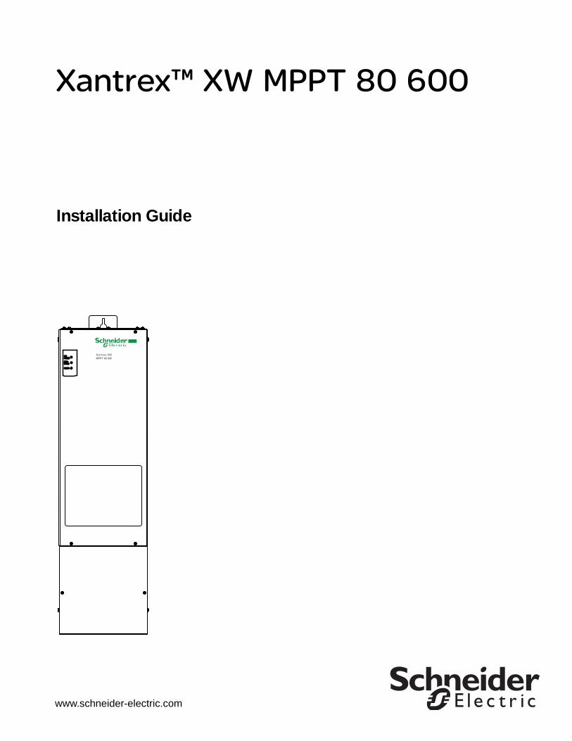
Xantrex XW �MPPT 80 600
Xantrex™ XW MPPT 80 600
Installation Guide
www.schneider-electric.com


Xantrex XW MPPT 80 600
Installation Guide
www.schneider-electric.com

Copyright and Contact
TrademarksSchneider Electric, the Schneider Electric logo, Xantrex, and Xanbus are trademarks or registered trademarks of the Schneider Electric group of companies. Other trademarks, registered trademarks, and product names are the property of their respective owners and are used herein for identification purposes only.
Notice of CopyrightCopyright © 2010 Xantrex Technology Inc. All rights reserved. No part of this document may be reproduced in any form or disclosed to third parties without the express written consent of:Xantrex Technology Inc.161-G South Vasco Road Livermore, California USA 94551Xantrex Technology Inc. reserves the right to revise this document and to periodically make changes to the content hereof without obligation or organization of such revisions or changes unless required to do so by prior arrangement.
Exclusion for DocumentationUNLESS SPECIFICALLY AGREED TO IN WRITING, XANTREX TECHNOLOGY INC. (“XANTREX”)
(A) MAKES NO WARRANTY AS TO THE ACCURACY, SUFFICIENCY OR SUITABILITY OF ANY TECHNICAL OR OTHER INFORMATION PROVIDED IN ITS MANUALS OR OTHER DOCUMENTATION;
(B) ASSUMES NO RESPONSIBILITY OR LIABILITY FOR LOSSES, DAMAGES, COSTS OR EXPENSES, WHETHER SPECIAL, DIRECT, INDIRECT, CONSEQUENTIAL OR INCIDENTAL, WHICH MIGHT ARISE OUT OF THE USE OF SUCH INFORMATION. THE USE OF ANY SUCH INFORMATION WILL BE ENTIRELY AT THE USER’S RISK; AND
(C) REMINDS YOU THAT IF THIS MANUAL IS IN ANY LANGUAGE OTHER THAN ENGLISH, ALTHOUGH STEPS HAVE BEEN TAKEN TO MAINTAIN THE ACCURACY OF THE TRANSLATION, THE ACCURACY CANNOT BE GUARANTEED. APPROVED XANTREX CONTENT IS CONTAINED WITH THE ENGLISH LANGUAGE VERSION WHICH IS POSTED AT WWW.SCHNEIDER-ELECTRIC.COM.
Date and RevisionNovember 2010 Revision A
Part Number975-0540-01-01
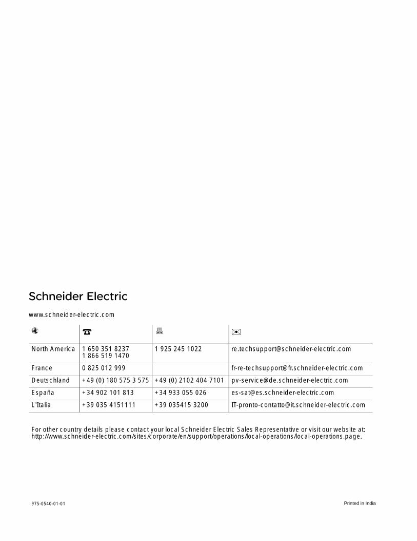
Contact Information
www.schneider-electric.com
☎ ✉North America 1 650 351 8237
1 866 519 14701 925 245 1022 [email protected]
France 0 825 012 999 [email protected]
Deutschland +49 (0) 180 575 3 575 +49 (0) 2102 404 7101 [email protected]
España +34 902 101 813 +34 933 055 026 [email protected]
L'Italia +39 035 4151111 +39 035415 3200 [email protected]
For other country details please contact your local Schneider Electric Sales Representative or visit our website at:http://www.schneider-electric.com/sites/corporate/en/support/operations/local-operations/local-operations.page

About This GuidePurpose The purpose of this Guide is to provide explanations and procedures for
installing and troubleshooting the Schneider Electric Xantrex XW MPPT 80 600.
Scope This Guide provides safety guidelines, detailed planning and setup information, procedures for installing the unit, and information about troubleshooting. It does not provide details about particular brands of photovoltaic (PV) panels or batteries.
Audience This Guide is intended for qualified personnel who need to install the unit. Qualified personnel have training, knowledge, and experience in:
• Installing electrical equipment and PV power systems (up to 1000 V).
• Applying all applicable installation codes.
• Analyzing and reducing the hazards involved in performing electrical work.
• Selecting and using Personal Protective Equipment (PPE).
Only qualified personnel should perform the installation, commissioning, and maintenance of the unit.
Organization This Guide is organized into three chapters and one appendix:
• Chapter 1 describes features and functions of the Xantrex XW MPPT 80 600.
• Chapter 2 provides installation instructions for the Xantrex XW MPPT 80 600. Before installing the unit, read this entire chapter.
• Chapter 3 contains information about identifying and resolving possible problems that may arise while using a Xantrex XW MPPT 80 600.
• Appendix A provides the specifications for the Xantrex XW MPPT 80 600.
Conventions Used This Guide uses the term “unit” to refer to the Xantrex XW MPPT 80 600.
This Guide uses the following conventions for conveying important safety related information:
DANGER
DANGER indicates an imminently hazardous situation which, if not avoided, will result in death or serious injury.
WARNING
WARNING indicates a potentially hazardous situation which, if not avoided, can result in death or serious injury.
975-0540-01-01 iiiThis manual is intended for use by qualified personnel only
About This Guide
Abbreviations and Acronyms
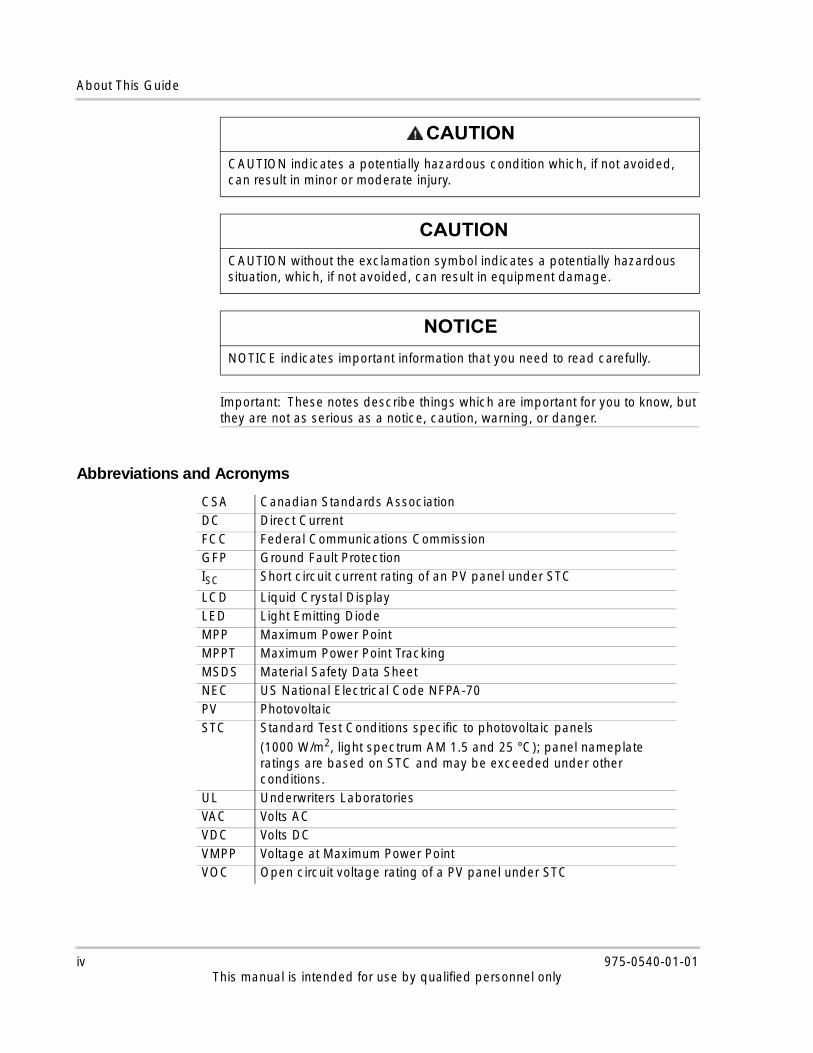
CAUTION
CAUTION indicates a potentially hazardous condition which, if not avoided, can result in minor or moderate injury.
CAUTION
CAUTION without the exclamation symbol indicates a potentially hazardous situation, which, if not avoided, can result in equipment damage.
NOTICE
NOTICE indicates important information that you need to read carefully.
Important: These notes describe things which are important for you to know, but they are not as serious as a notice, caution, warning, or danger.
CSA Canadian Standards AssociationDC Direct CurrentFCC Federal Communications CommissionGFP Ground Fault ProtectionISC Short circuit current rating of an PV panel under STC
LCD Liquid Crystal DisplayLED Light Emitting DiodeMPP Maximum Power PointMPPT Maximum Power Point TrackingMSDS Material Safety Data SheetNEC US National Electrical Code NFPA-70PV Photovoltaic STC Standard Test Conditions specific to photovoltaic panels
(1000 W/m2, light spectrum AM 1.5 and 25 °C); panel nameplate ratings are based on STC and may be exceeded under other conditions.
UL Underwriters LaboratoriesVAC Volts ACVDC Volts DCVMPP Voltage at Maximum Power PointVOC Open circuit voltage rating of a PV panel under STC
iv 975-0540-01-01This manual is intended for use by qualified personnel only

About This Guide
Related Information
You can find information about using the unit in the Xantrex XW MPPT 80 600 Operation Guide (Document Part Number 975-0560-01-01). It is provided with the unit and is also available at www.schneider-electric.com.
You can find more information about Schneider Electric as well as its products and services at www.schneider-electric.com.
975-0540-01-01 vThis manual is intended for use by qualified personnel only

About This Guide
vi 975-0540-01-01This manual is intended for use by qualified personnel only
Important Safety Instructions
General Safety Instructions
DANGER
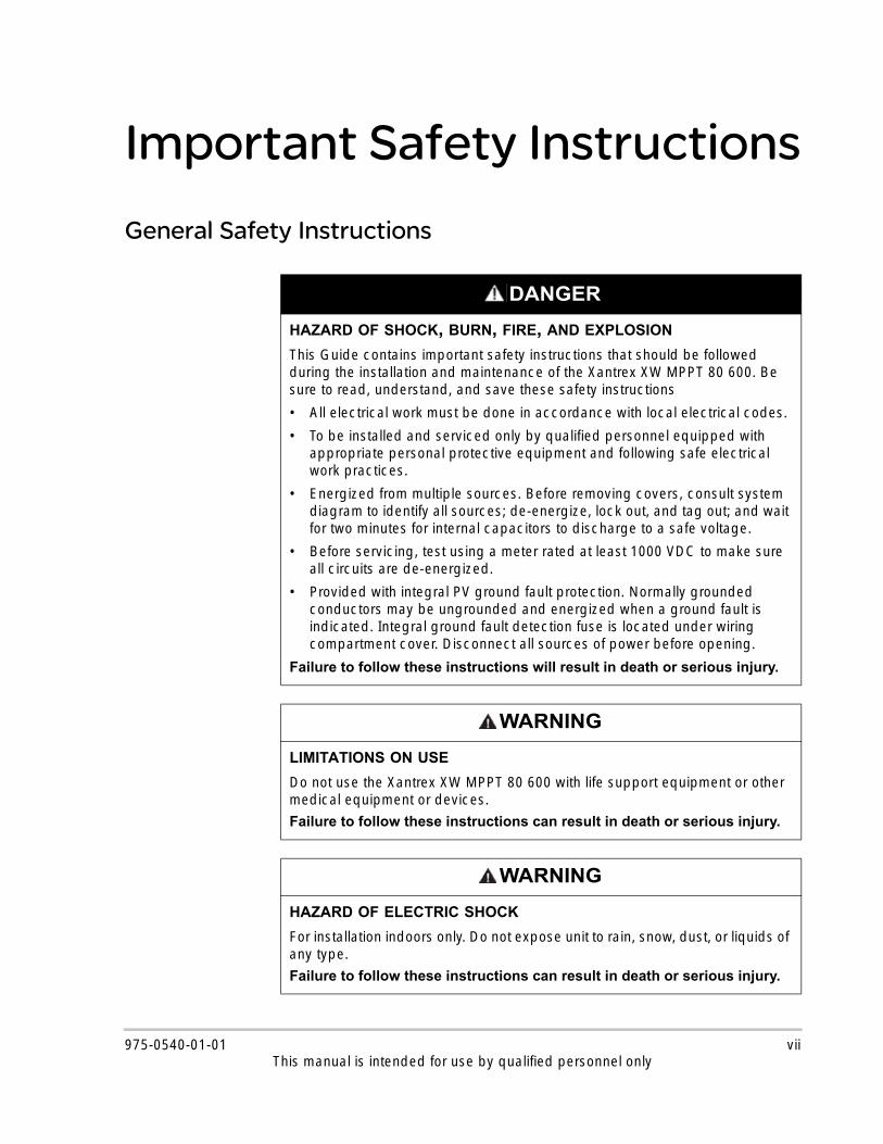
HAZARD OF SHOCK, BURN, FIRE, AND EXPLOSION
This Guide contains important safety instructions that should be followed during the installation and maintenance of the Xantrex XW MPPT 80 600. Be sure to read, understand, and save these safety instructions
• All electrical work must be done in accordance with local electrical codes.
• To be installed and serviced only by qualified personnel equipped with appropriate personal protective equipment and following safe electrical work practices.
• Energized from multiple sources. Before removing covers, consult system diagram to identify all sources; de-energize, lock out, and tag out; and wait for two minutes for internal capacitors to discharge to a safe voltage.
• Before servicing, test using a meter rated at least 1000 VDC to make sure all circuits are de-energized.
• Provided with integral PV ground fault protection. Normally grounded conductors may be ungrounded and energized when a ground fault is indicated. Integral ground fault detection fuse is located under wiring compartment cover. Disconnect all sources of power before opening.
Failure to follow these instructions will result in death or serious injury.
WARNING
LIMITATIONS ON USE
Do not use the Xantrex XW MPPT 80 600 with life support equipment or other medical equipment or devices.
Failure to follow these instructions can result in death or serious injury.
WARNING
HAZARD OF ELECTRIC SHOCK
For installation indoors only. Do not expose unit to rain, snow, dust, or liquids of any type.
Failure to follow these instructions can result in death or serious injury.
975-0540-01-01 viiThis manual is intended for use by qualified personnel only
Safety
Battery Safety Information
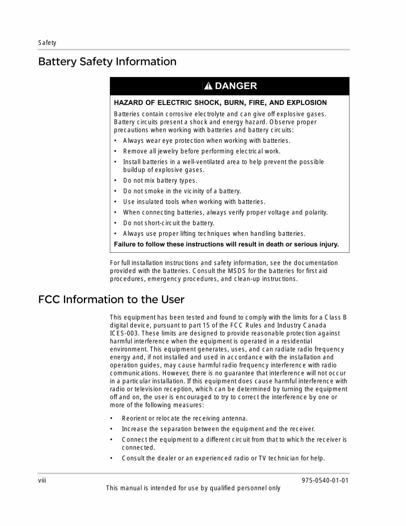
For full installation instructions and safety information, see the documentation provided with the batteries. Consult the MSDS for the batteries for first aid procedures, emergency procedures, and clean-up instructions.
FCC Information to the UserThis equipment has been tested and found to comply with the limits for a Class B digital device, pursuant to part 15 of the FCC Rules and Industry Canada ICES-003. These limits are designed to provide reasonable protection against harmful interference when the equipment is operated in a residential environment. This equipment generates, uses, and can radiate radio frequency energy and, if not installed and used in accordance with the installation and operation guides, may cause harmful radio frequency interference with radio communications. However, there is no guarantee that interference will not occur in a particular installation. If this equipment does cause harmful interference with radio or television reception, which can be determined by turning the equipment off and on, the user is encouraged to try to correct the interference by one or more of the following measures:
• Reorient or relocate the receiving antenna.
• Increase the separation between the equipment and the receiver.
• Connect the equipment to a different circuit from that to which the receiver is connected.
• Consult the dealer or an experienced radio or TV technician for help.
DANGER
HAZARD OF ELECTRIC SHOCK, BURN, FIRE, AND EXPLOSION
Batteries contain corrosive electrolyte and can give off explosive gases. Battery circuits present a shock and energy hazard. Observe proper precautions when working with batteries and battery circuits:
• Always wear eye protection when working with batteries.
• Remove all jewelry before performing electrical work.
• Install batteries in a well-ventilated area to help prevent the possible buildup of explosive gases.
• Do not mix battery types.
• Do not smoke in the vicinity of a battery.
• Use insulated tools when working with batteries.
• When connecting batteries, always verify proper voltage and polarity.
• Do not short-circuit the battery.
• Always use proper lifting techniques when handling batteries.
Failure to follow these instructions will result in death or serious injury.
viii 975-0540-01-01This manual is intended for use by qualified personnel only

Contents
Important Safety Instructions- - - - - - - - - - - - - - - - - - - - - - - - - - - - - - - - - - - - vii1 IntroductionFeatures - - - - - - - - - - - - - - - - - - - - - - - - - - - - - - - - - - - - - - - - - - - - - - - - - - - - - - - - - - - - - - - 1–2Charge Controlling - - - - - - - - - - - - - - - - - - - - - - - - - - - - - - - - - - - - - - - - - - - - - - - - - - - - - - - - 1–2
2 InstallationPV Array Requirements - - - - - - - - - - - - - - - - - - - - - - - - - - - - - - - - - - - - - - - - - - - - - - - - - - - - - 2–2Mounting - - - - - - - - - - - - - - - - - - - - - - - - - - - - - - - - - - - - - - - - - - - - - - - - - - - - - - - - - - - - - - - 2–3
Choosing a Location - - - - - - - - - - - - - - - - - - - - - - - - - - - - - - - - - - - - - - - - - - - - - - - - - - - - 2–3Removing the Wiring Compartment Cover - - - - - - - - - - - - - - - - - - - - - - - - - - - - - - - - - - - - - 2–5Removing Knockouts - - - - - - - - - - - - - - - - - - - - - - - - - - - - - - - - - - - - - - - - - - - - - - - - - - - 2–6Mounting the Unit - - - - - - - - - - - - - - - - - - - - - - - - - - - - - - - - - - - - - - - - - - - - - - - - - - - - - - 2–7
PV Grounding- - - - - - - - - - - - - - - - - - - - - - - - - - - - - - - - - - - - - - - - - - - - - - - - - - - - - - - - - - - - 2–8Chassis Grounding - - - - - - - - - - - - - - - - - - - - - - - - - - - - - - - - - - - - - - - - - - - - - - - - - - - - - 2–8Internal Ground Fault Protection - - - - - - - - - - - - - - - - - - - - - - - - - - - - - - - - - - - - - - - - - - - - 2–8
Wiring - - - - - - - - - - - - - - - - - - - - - - - - - - - - - - - - - - - - - - - - - - - - - - - - - - - - - - - - - - - - - - - - - 2–9Connector Locations - - - - - - - - - - - - - - - - - - - - - - - - - - - - - - - - - - - - - - - - - - - - - - - - - - - - 2–9Wire Size and Over-current Protection Requirements - - - - - - - - - - - - - - - - - - - - - - - - - - - - 2–10
PV Current Rating - - - - - - - - - - - - - - - - - - - - - - - - - - - - - - - - - - - - - - - - - - - - - - - - - - 2–10Minimum Wire Gauge - - - - - - - - - - - - - - - - - - - - - - - - - - - - - - - - - - - - - - - - - - - - - - - 2–10Over-current Protection - - - - - - - - - - - - - - - - - - - - - - - - - - - - - - - - - - - - - - - - - - - - - - 2–11
Connecting the Unit - - - - - - - - - - - - - - - - - - - - - - - - - - - - - - - - - - - - - - - - - - - - - - - - - - - 2–12Connecting Multiple PV Array Strings to One Unit - - - - - - - - - - - - - - - - - - - - - - - - - - - - - - - - - 2–13Connecting Multiple Units - - - - - - - - - - - - - - - - - - - - - - - - - - - - - - - - - - - - - - - - - - - - - - - - - - 2–13Auxiliary Output Connections- - - - - - - - - - - - - - - - - - - - - - - - - - - - - - - - - - - - - - - - - - - - - - - - 2–15Network Installation- - - - - - - - - - - - - - - - - - - - - - - - - - - - - - - - - - - - - - - - - - - - - - - - - - - - - - - 2–16
Network Components - - - - - - - - - - - - - - - - - - - - - - - - - - - - - - - - - - - - - - - - - - - - - - - - - - 2–17Ordering Network Components - - - - - - - - - - - - - - - - - - - - - - - - - - - - - - - - - - - - - - - - 2–17
Network Layout - - - - - - - - - - - - - - - - - - - - - - - - - - - - - - - - - - - - - - - - - - - - - - - - - - - - - - - 2–18Connecting Network Cables Between Multiple Units - - - - - - - - - - - - - - - - - - - - - - - - - - - - 2–18
Installing the Battery Temperature Sensor- - - - - - - - - - - - - - - - - - - - - - - - - - - - - - - - - - - - - - - 2–19Commissioning- - - - - - - - - - - - - - - - - - - - - - - - - - - - - - - - - - - - - - - - - - - - - - - - - - - - - - - - - - 2–21
Setting the Device Number - - - - - - - - - - - - - - - - - - - - - - - - - - - - - - - - - - - - - - - - - - - - - - 2–21Configuring Connections and Charger Settings - - - - - - - - - - - - - - - - - - - - - - - - - - - - - - - - 2–22Copying a Unit’s Settings to Another Unit - - - - - - - - - - - - - - - - - - - - - - - - - - - - - - - - - - - - 2–23Starting the Unit - - - - - - - - - - - - - - - - - - - - - - - - - - - - - - - - - - - - - - - - - - - - - - - - - - - - - - 2–24
975-0540-01-01 ixThis manual is for use by qualified personnel only

Contents
3 TroubleshootingPV Charge Control Troubleshooting- - - - - - - - - - - - - - - - - - - - - - - - - - - - - - - - - - - - - - - - - - - - 3–2Replacing the Ground Fault Protection Fuse- - - - - - - - - - - - - - - - - - - - - - - - - - - - - - - - - - - - - - 3–4Ground Faults in a Normally Ungrounded Array - - - - - - - - - - - - - - - - - - - - - - - - - - - - - - - - - - - 3–5
A SpecificationsElectrical Specifications - - - - - - - - - - - - - - - - - - - - - - - - - - - - - - - - - - - - - - - - - - - - - - - - - - - - A–2
MPPT Voltage Range - - - - - - - - - - - - - - - - - - - - - - - - - - - - - - - - - - - - - - - - - - - - - - - - - - - A–3Operating Below the PV Array Voltage Full Power Range - - - - - - - - - - - - - - - - - - - - - - - - - - A–3
Default Battery Charger Settings - - - - - - - - - - - - - - - - - - - - - - - - - - - - - - - - - - - - - - - - - - - - - - A–4Mechanical Specifications - - - - - - - - - - - - - - - - - - - - - - - - - - - - - - - - - - - - - - - - - - - - - - - - - - A–5Recommended Accessories - - - - - - - - - - - - - - - - - - - - - - - - - - - - - - - - - - - - - - - - - - - - - - - - - A–5Optional Accessories - - - - - - - - - - - - - - - - - - - - - - - - - - - - - - - - - - - - - - - - - - - - - - - - - - - - - - A–6Regulatory Approvals - - - - - - - - - - - - - - - - - - - - - - - - - - - - - - - - - - - - - - - - - - - - - - - - - - - - - - A–6
Index - - - - - - - - - - - - - - - - - - - - - - - - - - - - - - - - - - - - - - - - - - - - - - - - - - - - - - - - - - - - - - - - - - - - IX–1
x 975-0540-01-01This manual is for use by qualified personnel only

1 Introduction
Chapter 1 describes features and functions of the Xantrex XW MPPT 80 600.For information on: See:
“Features” page 1–2
“Charge Controlling” page 1–2
This manual is intended for use by qualified personnel only

Introduction
FeaturesThe Xantrex XW MPPT 80 600 is a photovoltaic charge controller that tracks the maximum power point of a PV array to deliver the maximum available current for optimum charging of batteries. The unit can be used with 24 and 48 VDC battery systems only.
The unit is designed to regulate the available power from a PV source only. It is not designed to regulate power from other types of power sources.
The unit can be installed (in single or multi-unit configurations) with a Xantrex XW Hybrid Inverter/Charger or as a stand alone battery charger. However, it is recommended that, at minimum, a Xantrex XW System Control Panel (Xantrex XW SCP) or Xantrex Gateway be included in the system (see “Optional Accessories” on page A–6 for product part numbers). The Xantrex XW SCP provides both status information and the ability to change settings, while the Xantrex Gateway (access via a personal computer) provides status only.
Charge Controlling
The unit can regulate PV array current at an appropriate level for 24 or 48 V batteries. It produces up to 80 amps of charging current for both battery voltages up to 2560 watts (24 V) or 4800 watts (48 V).
The unit controls how the batteries are charged by the DC source (the PV array). It can be configured to use a two-stage (no float) or three-stage charging process to maintain battery voltage at bulk, absorption, or float levels. When charging, the unit regulates the battery voltage and the output current based on the amount of DC power available from the PV array and the state of charge of the battery. See the Xantrex XW MPPT 80 600 Operation Guide for more information on two-stage and three-stage charging as well as the different stages.
1–2 975-0540-01-01This manual is intended for use by qualified personnel only

2 Installation
Chapter 2 provides installation instructions for the Xantrex XW MPPT 80 600. Before installing the unit, read this entire chapter. For information on: See:
“PV Array Requirements” page 2–2
“Mounting” page 2–3
“PV Grounding” page 2–8
“Wiring” page 2–9
“Connecting Multiple PV Array Strings to One Unit”
page 2–13
“Connecting Multiple Units” page 2–13
“Auxiliary Output Connections” page 2–15
“Network Installation” page 2–16
“Installing the Battery Temperature Sensor”
page 2–19
“Commissioning” page 2–21
This manual is intended for use by qualified personnel only

Installation
PV Array Requirements
Each unit must be connected to its own PV array. Up to three PV array strings can be paralleled. See “Connecting Multiple PV Array Strings to One Unit” on page 2–13.
A design guide is available to assist with choosing an optimal PV array size.
1. Go to www.schneider-electric.com.
2. Open the Products and Services tab and click Renewable Energies.
3. Navigate to your specific product page.
4. Click Sizing Tools.
WARNING
HAZARD OF ELECTRIC SHOCK, BURNS, FIRE, AND EXPLOSION
Installation of this equipment should only be planned and performed by qualified personnel in accordance with all applicable installation codes. See “Audience” on page iii for the definition of qualified personnel.
Failure to follow these instructions can result in death or serious injury.
WARNING
HAZARD OF ELECTRIC SHOCK, BURNS, FIRE, AND EXPLOSION
RISK OF EQUIPMENT DAMAGE
Unsafe conditions and damage to the unit may result if the instructions and electrical, physical, and environmental installation specifications in this Guide are not obeyed.
Failure to follow these instructions can result in death or serious injury.
Important: The following information only provides general guidelines. PV array installation is subject to installation codes and, in some areas, inspection and approval by the authority having jurisdiction. For example, installations in the USA must be compliant with NFPA 70 and in particular Article 690.
WARNING
HAZARD OF SHOCK
The PV array voltage must never exceed 600 VOC (open circuit voltage) under any conditions. The PV array Isc (short circuit current) must not exceed 28 A at STC (based on array nameplate ratings) or 35 ADC absolute maximum under any conditions.
Failure to follow these instructions can result in death or serious injury.
2–2 975-0540-01-01This manual is intended for use by qualified personnel only
Mounting
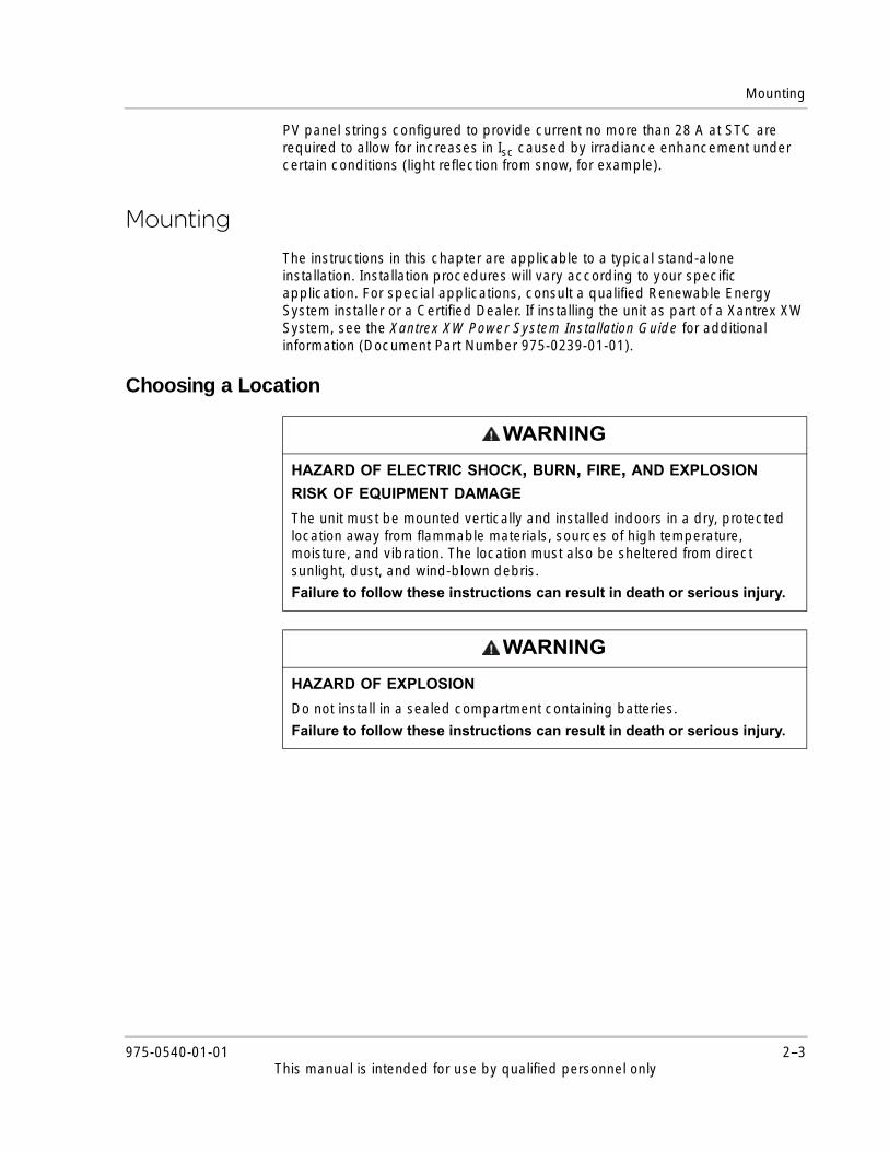
PV panel strings configured to provide current no more than 28 A at STC are required to allow for increases in Isc caused by irradiance enhancement under certain conditions (light reflection from snow, for example).
Mounting
The instructions in this chapter are applicable to a typical stand-alone installation. Installation procedures will vary according to your specific application. For special applications, consult a qualified Renewable Energy System installer or a Certified Dealer. If installing the unit as part of a Xantrex XW System, see the Xantrex XW Power System Installation Guide for additional information (Document Part Number 975-0239-01-01).
Choosing a Location
WARNING
HAZARD OF ELECTRIC SHOCK, BURN, FIRE, AND EXPLOSION RISK OF EQUIPMENT DAMAGE
The unit must be mounted vertically and installed indoors in a dry, protected location away from flammable materials, sources of high temperature, moisture, and vibration. The location must also be sheltered from direct sunlight, dust, and wind-blown debris.
Failure to follow these instructions can result in death or serious injury.
WARNING
HAZARD OF EXPLOSION
Do not install in a sealed compartment containing batteries.
Failure to follow these instructions can result in death or serious injury.
975-0540-01-01 2–3This manual is intended for use by qualified personnel only

Installation
For optimal and safe operation, make sure there is adequate clearance around the unit. See Table 2-1 and Figure 2-1. If clearances are reduced below these minimums, charging performance may be impaired.
Table 2-1 Minimum Clearance Requirements
Location Minimum Clearance
Above and below
6 inches (150 mm). Do not mount units in a vertical stack.
Note: One unit can be mounted on the side of the Xantrex XW Power Distribution Panela (part number 865-1015). For more information, see the Xantrex XW Power System Installation Guide, available with the Xantrex XW Hybrid Inverter/Charger. Other installations must follow the guidelines in this Guide.
a.The Xantrex XW Power Distribution Panel is not available outside North America.
In front Sufficient room to allow for easy access to see the LEDs and to perform maintenance.
Sides No clearance requirement.
Figure 2-1 Minimum Clearance Requirements
6 inches (150 mm) on top and below
2–4 975-0540-01-01This manual is intended for use by qualified personnel only

Mounting
Removing the Wiring Compartment Cover
Before mounting, remove the wiring compartment cover to access the mounting holes and the wiring terminals. The wiring compartment cover is secured with two screws on the front of the unit. See Figure 2-2.
The wiring compartment (Figure 2-3) contains a flexible Lexan™ barrier used to segregate battery and PV wire routing. In some instances, you must manipulate this barrier to provide a passage for battery or PV cables running through the wiring compartment. In this scenario, you must take care to avoid intermingling of PV and battery wires.
DANGER
HAZARD OF ELECTRIC SHOCK AND ENERGY
Before removing the wiring compartment cover, make sure all sources of electricity have been disconnected for at least 2 minutes. Before energizing the unit, make sure the wiring compartment cover has been replaced with all fasteners.
Failure to follow these instructions will result in death or serious injury.
Figure 2-2 Removing the Wiring Compartment Cover
Remove two screws to access the wiring terminals.
Figure 2-3 Wiring Compartment with Lexan Barrier
Lexan barrier
975-0540-01-01 2–5This manual is intended for use by qualified personnel only

Installation
Removing Knockouts
Fourteen knockouts are provided for conduit or cable entry into the unit (see Figure 2-4 and Figure 2-5):
• Three single (one on each side and one on the back) for battery wires (44.0 mm).
• Two single on the back and six dual on the sides (three on each side) for PV array wires (35.0 mm).
• Three dual (one on each side and one on the back) for routing BTS and network cables (28.2 mm).
When removing knockouts, make sure no metal shavings or fragments fall into the wiring compartment. Use bushings or conduits to help protect the wiring from damage from rough edges around the knockout holes.
CAUTION
RISK OF EQUIPMENT DAMAGE
Do not drill, cut, or punch holes in the unit. Use only the knockouts provided for conduit entry.
Failure to follow these instructions can result in equipment damage.
Figure 2-4 Knockout Dimensions
26.4 (1.03)29.0 (1.14)
45.4 (1.78)55.2 (2.17)85.5 (3.37)
22
.8 (
0.9
0)
62
.3 (
2.4
5)
82
.8 3
.26
)
102
.5 (
4.0
3)
35.0 (1.38)
85.0 (3.35)
110.0 (4.33)
169.0 (6.65)
22.8
(0.9
0)
146
.5 (
5.1
8)
28.2 (1.11)/ 22.2(0.87)DUAL KNOCKOUT
35.0 (1.38) KNOCKOUT 2PL 44.0 (1.73) KNOCKOUT
150.0 (5.90)
6.5 (0.25)
2–6 975-0540-01-01This manual is intended for use by qualified personnel only

Mounting
Mounting the Unit
The unit must be vertically mounted to the wall using three ¼-inch × ½-inch (6.35 mm × 12.5 mm) pan-head screws. It can also be mounted on the side of the Xantrex XW Power Distribution Panel (hardware provided with the unit). For more information, see the Xantrex XW Power System Installation Guide.
To mount the unit (see Figure 2-6):
1. Remove the wiring compartment cover (see page 2–5).
2. Mark the location of the keyhole slot on the wall.
3. Secure the top mounting screw in the location marked. Leave the screw head backed out approximately ¼ inch (6 mm).
4. Place the controller onto the screw and pull it down into the keyhole slot.
5. Insert two screws in the two mounting holes provided to secure the unit to the wall.
Figure 2-5 Dimensions and Knockout Locations7
64
.0 (
30
.0)
220.5 (8.68)
44.0 (1.73) KNOCKOUT
28.2 (1.11)/ 22.2(0.87)DUAL KNOCKOUT
35.0 (1.38)/ 28.2 (1.11)DUAL KNOCKOUT 3PL
108.4 (4.27)
61
.9 (
2.4
4)
67
3.4
(2
6.5
)
219.7 (8.65)
Keyhole slot for wall mounting
All measurements in mm (in.)
975-0540-01-01 2–7This manual is intended for use by qualified personnel only

Installation
PV Grounding
The unit can be configured to be compatible with either negative-grounded, positive-grounded, or ungrounded (floating) PV systems. For information about routing the ground connection, see Figure 2-9 on page 2–14.
Chassis Grounding
The recommended size of the chassis ground conductor is #8 AWG (8.5 mm2)1. For ground conductor requirements for your specific installation, consult your local electrical code.
Internal Ground Fault Protection
The unit has two types of ground fault protection. For grounded arrays, the unit has two PV ground fault protection fuse holders (for use with fuses rated 600 VDC, 1 A maximum) located inside the wiring compartment. The fuse provides both a ground bond and ground fault protection for grounded PV array systems. For ungrounded arrays, the unit detects the resistance between the array and ground, and it indicates a fault if the resistance is too low. The unit is configured at the factory for an ungrounded PV array connection. For both types of ground fault protection, if the unit determines that a ground fault has occurred, it will cease operating and will indicate a fault on the unit’s display and over the Xantrex Xanbus™ network (if used).
Figure 2-6 Mounting the Unit
Secure with two more screws.
Place keyhole slot over the mounting screw.
¼"(6 mm)
1.Based on the NEC (NFPA 70) Article 250 for 100 A maximum battery fuse.
2–8 975-0540-01-01This manual is intended for use by qualified personnel only
Wiring
WiringThe following sections provide information about wiring.
Connector Locations
Terminal connectors for DC wiring are located inside the wiring compartment. The labels above the DC wiring terminals identify all the connection points. See Figure 2-8.
WARNING
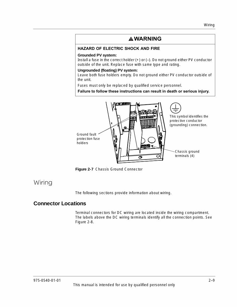
HAZARD OF ELECTRIC SHOCK AND FIRE
Grounded PV system:Install a fuse in the correct holder (+) or (–). Do not ground either PV conductor outside of the unit. Replace fuse with same type and rating.
Ungrounded (floating) PV system:Leave both fuse holders empty. Do not ground either PV conductor outside of the unit.
Fuses must only be replaced by qualified service personnel.
Failure to follow these instructions can result in death or serious injury.
Figure 2-7 Chassis Ground Connector
Chassis ground terminals (4)
This symbol identifies the protective conductor (grounding) connection.
Ground fault protection fuse holders
975-0540-01-01 2–9This manual is intended for use by qualified personnel only

Installation
A label providing details on each connector and torque requirements for each terminal is affixed to the inside of the wiring compartment cover plate.
Wire Size and Over-current Protection Requirements
PV Current Rating
The PV input of the unit is electronically limited to 23 A under all conditions of operation. The gauge of PV wiring must coordinate with local electrical code requirements and the total array short circuit current, based on the published ISC rating of the PV panels installed in the system.
Minimum Wire Gauge
For installations where the PV array output short-circuit rating is the maximum allowable (28 A at STC), the recommended smallest wire size is #8 AWG (10 mm2)1 copper wire with a 75 °C (167 °F) insulation rating. The wire gauge requirements vary with those of the local jurisdiction. For details, consult the electrical code.
Figure 2-8 DC Terminal Connector Locations
B ATTE R Y+_
NE G. GND P V .
P V - P V +
P OS . GND PV.
XANB USXANB US B TS AUX
T ER MINAL T OR QUE
25 lbf.in (2.8 N m) 15 lbf.in (1.7 N m)
T ER MINAL T OR QUE
COM NO NC
WARNING
HAZARD OF ELECTRIC SHOCK, ENERGY, AND FIRE
The wiring, over-current protection devices (fuses and circuit breakers), and installation methods used must conform to all national and local electrical code requirements. Wiring must be protected from physical damage with appropriate methods such as the use of conduit and strain relief clamps.
To prevent intermingling with hazardous voltage-level wiring, the BTS, auxiliary output, and network cables must pass through a different conduit than the PV and battery cables.
Failure to follow these instructions can result in death or serious injury.
1.Based on NEC Table 310-16.
2–10 975-0540-01-01This manual is intended for use by qualified personnel only
Wiring
Over-current Protection
If a fuse is used for over-current protection, a disconnect switch must also be provided between the fuse and the source of supply (the PV array or the battery). If a circuit breaker is used, it will serve both purposes of disconnection and over-current protection.
Battery Circuit For installations in the USA, the NEC requires that the battery circuit be protected with a device rated for 125% of the rating of the circuit. The DC-rated fuse or circuit breaker between the battery and the unit must be rated, at minimum,100 A and must not exceed the allowable over-current protection rating for the size of wire being used, in accordance with applicable electrical codes.
PV Circuit A properly rated PV disconnect switch is mandatory between the PV array and the unit, and it must be rated for 600 VDC and have a sufficient current rating for your specific installation.
For installations with three or more PV array strings connected to one unit, each string must be fused before being combined at the PV input terminal connector inside the wiring compartment. See “Connecting Multiple PV Array Strings to One Unit” on page 2–13 for more information.
You can use separate disconnect switches for each PV string and combine these in the unit, as long as the following conditions are met:
• Each PV string is fused.
• All disconnects are placed side by side, so that it is clear that all need to be thrown for a complete and visible PV disconnect.
WARNING
HAZARD OF ELECTRIC SHOCK, ENERGY, AND FIRE
Over-current protection must be provided, external to the unit, to protect the PV and battery wiring. External disconnecting means must also be provided for the PV and battery circuits. Consult local electrical codes to establish the correct fuse or circuit breaker ratings and for required locations of protection and disconnecting means.
Failure to follow these instructions can result in death or serious injury.
DANGER
HAZARD OF ELECTRIC SHOCK
The PV disconnect switch can only be installed safely if the array is covered with an opaque (dark) material.
Failure to follow these instructions will result in death or serious injury.
975-0540-01-01 2–11This manual is intended for use by qualified personnel only
Installation
Connecting the Unit
The following procedure is illustrated in Figure 2-9 on page 2–14.
To connect the unit in a negative-grounded system:
1. Make sure the PV array disconnect and battery disconnect are turned off.
2. Install a cable clamp in each knockout being used.
3. Ground the unit. Connect a grounding conductor between a unit ground lug and the grounding electrode (as shown in Figure 2-9).
4. Connect the PV array’s negative (–) output to the unit terminal marked PV –.
5. Connect the PV array’s positive (+) output to the PV array disconnect.
6. Route another positive (+) cable from the other end of the PV disconnect to the unit terminal marked PV +.
7. Connect the negative (–) battery cable to the unit terminal marked BAT –.
8. Connect a positive (+) cable from the unit terminal marked BAT + to the battery disconnect.
9. Connect a second positive (+) cable to the other side of the battery disconnect and connect to the positive (+) battery terminal.
10. Torque the unit’s battery terminals to 25 lbf.in (2.8 Nm) and the PV terminals to 15 lbf.in (1.7 Nm). Allow some slack on the cables within the unit and secure the wiring with strain reliefs or cable clamps.
DANGER
HAZARD OF ELECTRIC SHOCK
Whenever a PV array is exposed to light, a shock hazard exists at the output wires or exposed terminals. Open the array disconnect switch before making the connections.
Failure to follow these instructions will result in death or serious injury.
CAUTION
RISK OF REVERSE POLARITY DAMAGE
Before energizing the unit from either the PV array or from the battery, check the polarity of all power connections. Positive (+) must be connected to positive (+). Negative (–) must be connected to negative (–).
Failure to follow these instructions can result in equipment damage.
2–12 975-0540-01-01This manual is intended for use by qualified personnel only

Connecting Multiple PV Array Strings to One Unit
To connect the unit in a positive-grounded or floating system:
◆ Follow the same steps as above for a negative-grounded unit, except note the location of the disconnect switch will vary as follows:
• For positive-grounded systems, the disconnect switch must be in the negative conductor.
• For floating systems, the disconnect switch must be a 2-pole type connected in both the positive and negative conductors.
In general, the same rules apply for disconnect switches as for battery circuits: they must be located in all ungrounded conductors. Requirements vary so consult local code.
Connecting Multiple PV Array Strings to One UnitThe unit has two three-pole connectors, allowing up to three PV array strings to be combined in the unit. Input connectors can accept #6 to #14 AWG (13.5 to 2.5 mm2) solid or stranded wire.
Connecting Multiple Units
In a multiple-unit installation, each unit must be connected to a separate PV array. See Figure 2-10. For other multiple-unit installation considerations, see “Network Installation” on page 2–16.
WARNING
HAZARD OF FIRE
Fuses are required when paralleling (combining) more than two PV strings. Fuses must be installed in a combiner or in a PV disconnect safety switch. These items are not provided with the unit.
Failure to follow these instructions can result in death or serious injury.
CAUTION
RISK OF EQUIPMENT DAMAGE
Make sure that each unit is correctly connected to its own PV array(s) and that no wires are interconnected between charge controllers.
Failure to follow these instructions can result in equipment damage.
975-0540-01-01 2–13This manual is intended for use by qualified personnel only
Installation
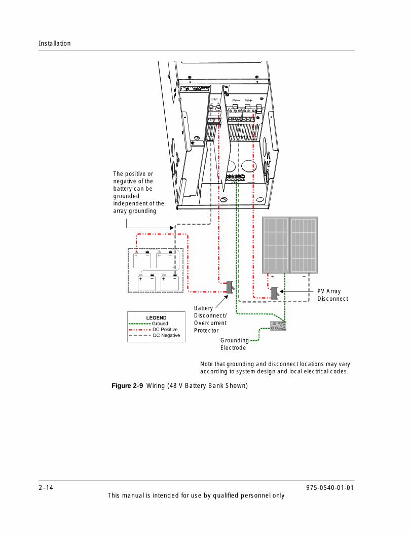
Figure 2-9 Wiring (48 V Battery Bank Shown)
Graphics\Source Files\wiring-charge-control_HV.vsd
LEGEND Ground
DC Positive DC Negative
BAT PVPV
PV Array Disconnect
Battery Disconnect/Overcurrent Protector
The positive or negative of the battery can be grounded independent of the array grounding
Grounding Electrode
Note that grounding and disconnect locations may vary according to system design and local electrical codes.
2–14 975-0540-01-01This manual is intended for use by qualified personnel only

Auxiliary Output Connections
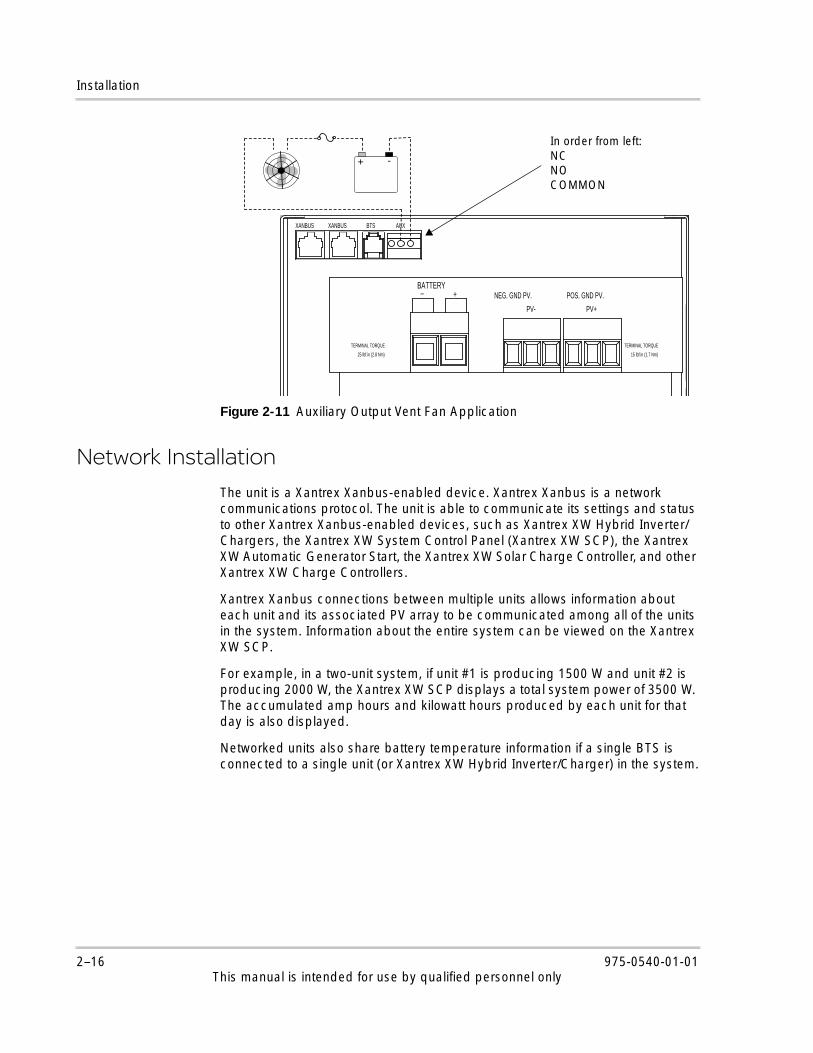
Auxiliary Output ConnectionsThe auxiliary output (dry relay contacts) provides a connector which can accept wire sized from #22 to #14 AWG (0.5 to 2.5 mm2), copper solid or stranded. As shown in Figure 2-11, the auxiliary output can control 12 VDC power to a fan to vent the battery compartment. For this application, the unit’s auxiliary output must be configured to activate when the batteries reach a pre-set voltage level. See “Configuring the Auxiliary Output” in the operation guide.
Figure 2-10 Multiple Unit DC Wiring
PV+PV– PV+PV–PV+PV– PV+PV–
+ + ––
Grounding not shown.
+ + ––
Incorrect wiring—systems are interconnected
Correct wiring—no interconnection between systems
PV Array #1 PV Array #2 PV Array #1 PV Array #2
WARNING
HAZARD OF FIRE
The auxiliary NO and NC dry contacts are rated up to 60 VDC and up to 8 A. Do not expose the auxiliary contacts to voltages or currents higher than this rating. Provide external over-current protection rated 8 A maximum.
Failure to follow these instructions can result in death or serious injury.
975-0540-01-01 2–15This manual is intended for use by qualified personnel only
Installation
Network Installation
The unit is a Xantrex Xanbus-enabled device. Xantrex Xanbus is a network communications protocol. The unit is able to communicate its settings and status to other Xantrex Xanbus-enabled devices, such as Xantrex XW Hybrid Inverter/Chargers, the Xantrex XW System Control Panel (Xantrex XW SCP), the Xantrex XW Automatic Generator Start, the Xantrex XW Solar Charge Controller, and other Xantrex XW Charge Controllers.
Xantrex Xanbus connections between multiple units allows information about each unit and its associated PV array to be communicated among all of the units in the system. Information about the entire system can be viewed on the Xantrex XW SCP.
For example, in a two-unit system, if unit #1 is producing 1500 W and unit #2 is producing 2000 W, the Xantrex XW SCP displays a total system power of 3500 W. The accumulated amp hours and kilowatt hours produced by each unit for that day is also displayed.
Networked units also share battery temperature information if a single BTS is connected to a single unit (or Xantrex XW Hybrid Inverter/Charger) in the system.
Figure 2-11 Auxiliary Output Vent Fan Application
-+
BATTERY+_
NEG. GND PV.
PV- PV+
POS. GND PV.
XANBUSXANBUS BTS AUX
TERMINAL TORQUE
25 lbf.in (2.8 Nm) 15 lbf.in (1.7 Nm)
TERMINAL TORQUE
In order from left:NCNOCOMMON
2–16 975-0540-01-01This manual is intended for use by qualified personnel only
Network Installation
Network Components
A Xantrex Xanbus network consists of the following components:
• Xantrex Xanbus-enabled devices: These include the unit, the Xantrex XW Hybrid Inverter/Charger, Xantrex XW Automatic Generator Start, and Xantrex XW SCP. The network can consist of up to three Xantrex XW Hybrid Inverter/Chargers, two units, one Xantrex XW Automatic Generator Start, and one Xantrex XW SCP. When only units are installed, up to ten can be networked together.
• Xantrex Xanbus power supply: The unit provides up to 7 W of power on the Xantrex Xanbus network to power one Xantrex XW SCP, one Xantrex XW Automatic Generator Start, and one Xantrex Gateway, not including the auxiliary supply. To reduce tare losses at night, you can configure the unit to shut off the Xantrex Xanbus power supply after sunset if you do not need device status information when it is not operating. See “Disabling Power Supplies at Night” in the Xantrex XW MPPT 80 600 Operation Guide for more information.
• Network cables: Each Xantrex Xanbus-enabled device is connected by a standard Ethernet (CAT 5 / CAT 5e) patch cable. Do not use crossover cable.
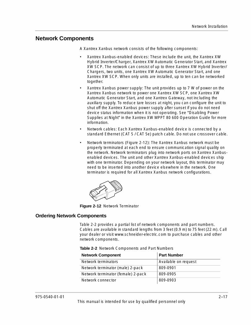
• Network terminators (Figure 2-12): The Xantrex Xanbus network must be properly terminated at each end to ensure communication signal quality on the network. Network terminators plug into network ports on Xantrex Xanbus-enabled devices. The unit and other Xantrex Xanbus-enabled devices ship with one terminator. Depending on your network layout, this terminator may need to be inserted into another device elsewhere in the network. One terminator is required for all Xantrex Xanbus network configurations.
Ordering Network Components
Table 2-2 provides a partial list of network components and part numbers. Cables are available in standard lengths from 3 feet (0.9 m) to 75 feet (22 m). Call your dealer or visit www.schneider-electric.com to purchase cables and other network components.
Figure 2-12 Network Terminator
Table 2-2 Network Components and Part Numbers
Network Component Part Number
Network terminators Available on request
Network terminator (male) 2-pack 809-0901
Network terminator (female) 2-pack 809-0905
Network connector 809-0903
975-0540-01-01 2–17This manual is intended for use by qualified personnel only

Installation
Network Layout
Xantrex Xanbus-enabled devices are connected with separate lengths of cable. The devices at each end of the chain must have a terminator inserted into their open network ports, as shown in Figure 2-13. Total cable length for the Xantrex Xanbus network must not exceed 131 feet (40 m).
Connecting Network Cables Between Multiple Units
Dual knockouts on the back and sides of the unit are provided for routing the Xantrex Xanbus network cable (see Figure 2-4 on page 2–6). See Figure 2-8 on page 2–10 for the location of the unit’s Xantrex Xanbus ports.
To connect network cables between multiple units:
1. Remove the wiring compartment cover from each unit (see “Removing the Wiring Compartment Cover” on page 2–5).
2. Remove a knockout from the back or either side of the unit, and then install an appropriately sized strain relief bushing for the network cable.
Figure 2-13 Network Layout
WARNING
HAZARD OF ELECTRIC SHOCK
Do not route the network cables in the same conduit or panel as the PV or battery input/output cables, and make sure the network cables are not mingled with conductors from those systems.
Failure to follow these instructions can result in death or serious injury.
BATTERY+_
NEG. GND PV.
PV- PV+
POS. GND PV.
XANBUSXANBUS BTS AUX
TERMINAL TORQUE
25 lbf.in (2.8 Nm) 15 lbf.in (1.7 Nm)
TERMINAL TORQUE
BATTERY+_
NEG. GND PV.
PV- PV+
POS. GND PV.
XANBUSXANBUS BTS AUX
TERMINAL TORQUE
25 lbf.in (2.8 Nm) 15 lbf.in (1.7 Nm)
TERMINAL TORQUE
Xantrex Xanbus cableNetwork terminator
Cable to next device
Important: Connect only Xantrex Xanbus-enabled devices. Although the cabling and connectors used in this network system are the same as ethernet connectors, this network is not an ethernet system. Important: Do not connect one end of the network to the other to make a ring or loop.
2–18 975-0540-01-01This manual is intended for use by qualified personnel only

Installing the Battery Temperature Sensor
3. Connect the network cable to a Xantrex Xanbus port in unit #1.
4. Route the cable to unit #2.
5. Connect the network cable to a Xantrex Xanbus port in unit #2.
6. Connect another network cable to unit #2 and route the cable to the next device in the network.
7. Make sure the factory-supplied network terminators are inserted into the empty Xantrex Xanbus ports in the devices at the beginning and end of the network. There should be no empty Xantrex Xanbus ports in any of the units.
Installing the Battery Temperature SensorInstalling a Battery Temperature Sensor (BTS) is recommended for optimum charging performance and battery life extension. If a BTS is not installed and the batteries will operate in hot or cold conditions, manually adjust the temperature settings to suit the conditions. See “Configuring Battery Characteristics and Battery Charging” in the Xantrex XW MPPT 80 600 Operation Guide.
Only one BTS is required per battery bank if multiple units or a complete Xantrex XW Power System with Xantrex XW Hybrid Inverter/Chargers are networked together using Xantrex Xanbus. All networked Xantrex XW Series devices share battery temperature information, and the BTS can be connected to a unit or a Xantrex XW Hybrid Inverter/Charger. If more than one BTS is used within the system, the highest reported temperature from all of the units with an attached BTS will be used as the battery temperature for the temperature compensation value of the battery charge algorithm.
See Figure 2-8 on page 2–10 for the location of the unit’s BTS port. Dual knockouts on the back and sides of the unit are provided for routing the BTS cable (see Figure 2-4 on page 2–6).
To install the BTS:
1. Remove the unit’s wiring compartment cover (see “Removing the Wiring Compartment Cover” on page 2–5).
2. Remove a knockout from the back or either side of the unit, and then install an appropriately sized strain relief bushing for the BTS cable.
3. Connect the ring terminal on the BTS directly to the negative battery terminal or positive battery terminal, or use the adhesive backing on the sensor back to attach the sensor to any side of the battery to be monitored. See Figure 2-14.
If connecting to the battery terminal, make sure the BTS does not prevent the power wiring from making the best possible contact with the battery terminal. If using the adhesive backing, install the BTS on the side of the battery below
Important: If the sensor cable is damaged and the wires are shorted, the unit registers a battery over temperature fault condition. If the BTS wires have been cut, the unit assumes that the BTS is not connected. A replacement BTS can be ordered from the manufacturer (part number 808-0232-02).
975-0540-01-01 2–19This manual is intended for use by qualified personnel only

Installation
the electrolyte level. It is best to place the sensor between batteries and place the batteries in an insulated box to reduce the influence of the ambient temperature outside the battery enclosure.
4. Pass the other end of the BTS cable through the knockout and strain relief bushing on the unit and insert the BTS plug into the BTS RJ-11 port. See Figure 2-15.
5. Replace the unit’s wiring compartment cover.
Figure 2-14 Attaching the BTS to a Battery Terminal
WARNING
HAZARD OF SHOCK
The BTS cable must not pass through the same conduit used for PV wiring and battery cables.
Failure to follow these instructions can result in death or serious injury.
Figure 2-15 Installing the BTS
+
+
–
–+
+
–
–
Insert the BTS plug into the unit’s BTS port.
Attach the BTS to a battery terminal or to the side of a battery.
2–20 975-0540-01-01This manual is intended for use by qualified personnel only

Commissioning
CommissioningUse the Xantrex XW SCP to commission a unit. For information about Xantrex XW SCP navigation and menus, see the appendix, “Xantrex XW System Control Panel Menus” in the Xantrex XW MPPT 80 600 Operation Guide. Before you begin, make sure you have important system information such as the nominal battery voltage, battery type, and battery bank capacity available.
If you are commissioning one unit, follow these two procedures:
1. “Setting the Device Number” on page 2–21
2. “Configuring Connections and Charger Settings” on page 2–22
3. “Starting the Unit” on page 2–24
If you are commissioning multiple units, follow these three procedures:
1. “Setting the Device Number” on page 2–21
2. “Configuring Connections and Charger Settings” on page 2–22
3. “Copying a Unit’s Settings to Another Unit” on page 2–23
4. “Starting the Unit” on page 2–24
When commissioning multiple units on the same Xantrex Xanbus network, make sure to set a unique device number and the correct battery connection for each unit. The connection is important to define so that system totals and other related information are displayed accurately.
Setting the Device Number
To set a device number for the unit:
1. Make sure a Xantrex XW SCP is attached to the unit’s Xantrex Xanbus network.
2. Close the DC disconnect (or use a selector switch to apply battery power to all units at the same time if commissioning multiple units). When a unit is powered up, it will detect that a Xantrex XW SCP is already operating on the network and be ready for configuration through the Xantrex XW SCP. Do not apply PV power at this point.
3. On the Xantrex XW SCP’s System Status home screen, press Enter.
The Select Device menu opens.
4. Use the arrow buttons to scroll to the unit to configure, and then press Enter. Each unit appears as XW MPPT80 xx, where xx is its device number.
The Setup menu opens.
5. To display the Advanced Settings menu item press the Enter, up arrow, and down arrow buttons simultaneously.
975-0540-01-01 2–21This manual is intended for use by qualified personnel only

Installation
6. Press Enter to select Advanced Settings.
The Config menu opens.
7. Scroll to Multi Unit Config, and then press Enter.
The Multi menu opens. The three LEDs on the unit you are configuring will start to flash when you enter this menu, providing visual confirmation of the unit you are configuring.
8. Scroll to Dev Number, and then press Enter. Scroll to set it to a number other than 00. Press Enter to confirm the new device number.
The device number can be set to any number between 01 and 31. If you are commissioning multiple units, the manufacturer recommends using 01 for the first unit.
9. Press Exit until the Select Device menu is displayed.
The unit appears as XW MPPT80 xx on the menu, where xx is the device number you selected.
10. Repeat steps 3 through 9 if you are commissioning multiple units.
Configuring Connections and Charger Settings
To configure connections and charger settings for a unit:
1. On the Select Device menu, select XW MPPT80 xx, where xx is the device number.
The Setup menu opens.
2. Press Enter to select Advanced Settings.
The Config menu opens.
3. Scroll to Multi Unit Config, and then press Enter.
The Multi menu opens.
4. Scroll to Connections, and then press Enter.
The Conn menu opens.
WARNING
HAZARD OF FIRE AND EXPLOSION
Battery charging settings must be configured by qualified personnel in accordance with the battery manufacturer's recommended charging instructions.
This section covers basic default settings. See the Xantrex XW MPPT 80 600 Operation Guide for additional configuration information and details including setting descriptions and value ranges.
Failure to follow these instructions can result in death or serious injury.
2–22 975-0540-01-01This manual is intended for use by qualified personnel only

Commissioning
5. Configure PV input (PV In) and DC output or the battery bank (DC Conn). If the system only has one battery bank, leave DC Conn at the default setting. The PV In setting allows you to differentiate which array is going to which unit. This setting is used for status reporting only, not for any internal controls. Setting PV In to a non-default value is optional.
6. Press Exit until the Config menu is displayed.
7. Scroll to Charger Settings, and then press Enter.
The Chgr menu opens.
8. Set the battery type (Batt Type), battery capacity (Batt Capacity), and any other charger settings required for your system. If you select Custom for the battery type, you can further configure bulk, absorption, float and other settings for the charge cycle in the Custom Settings menu that appears.
9. While in the Chgr menu, make sure the nominal battery voltage (Batt Voltage) is set correctly. The default value is 48 V. If your system is a 24 V battery system, then change it to 24 V.
10. Press Exit until the Select Device menu is displayed.
Copying a Unit’s Settings to Another Unit
Settings that are copied from one unit to another are:
• Batt Type
• Batt Capacity
• Max Chg Rate
• Charge Cycle
• ReCharge Volts
• Absorb Time
• Default Batt Temp
• Batt Voltage
• DC Conn
• Custom battery settings (if Custom battery type selected) including Eqlz Support, Eqlz Voltage, Bulk Voltage, Absorb Voltage, Float Voltage, and BattTempComp.
WARNING
HAZARD OF FIRE AND EXPLOSION
Do not copy settings from one unit to another unless the battery banks are identical – same size, type, and so on.
See the Xantrex XW MPPT 80 600 Operation Guide for additional configuration information and details including setting descriptions and value ranges.
Failure to follow these instructions will result in death or serious injury.
975-0540-01-01 2–23This manual is intended for use by qualified personnel only

Installation
If you are commissioning multiple units, copy the settings from the first unit configured to other units following these steps:
1. On the Select Device menu, select the next unit for configuration.
The Setup menu opens.
2. Press Enter to select Advanced Settings.
The Config menu opens.
3. Scroll to Copy from, and then press Enter to select the unit you want to copy from. Select the unit with the device number that matches the first unit you configured, and then press Enter again.
The settings are automatically copied from the selected unit.
4. Repeat steps 1 to 3 for the remaining units.
5. After you have finished configuring, press the Enter, up arrow, and down arrow buttons simultaneously to hide the Advanced Settings menu item.
Starting the Unit
To start the unit or units:
◆ Close the PV disconnect switch.
The unit or units start up and wait for a short period to determine that the input voltage is greater than the minimum operating voltage. After the input voltage exceeds the minimum operating voltage, the units begin operating.
Important: The Copy from command will not give you any indication that it has completed its task. To check that the charger settings have been copied properly, view some of the settings you originally configured.
2–24 975-0540-01-01This manual is intended for use by qualified personnel only

3 Troubleshooting
Chapter 3 contains information about identifying and resolving possible problems that may arise while using a Xantrex XW MPPT 80 600.
This manual is intended for use by qualified personnel only

Troubleshooting
PV Charge Control Troubleshooting
Table 3-1 lists possible problems that may arise with the unit.
DANGER
HAZARD OF ELECTRIC SHOCK, BURNS, FIRE, AND EXPLOSION
This chapter includes hazardous tasks to be performed only by qualified personnel equipped with appropriate personal protective equipment and following safe electrical work practices. Review the “Important Safety Instructions” beginning on page vii before proceeding.
Failure to follow these instructions will result in death or serious injury.
Table 3-1 PV Charge Control Problems
Problem Possible Cause Solution
Uneven output current between multiple units.
A. Solar arrays are supplying different amounts of current to each unit.
A. Check array output, but consider that this could be a normal operating condition if the arrays are located in different locations and/or point in different directions.
B. Charging set points are not all set the same.
B. Set controllers to the same settings.
C. Excess voltage drop in wiring causing controllers to measure the battery voltage differently and regulate accordingly.
C. Check wiring. Upgrading or shortening the wire run may be required.
D. Chargers are in constant voltage (absorption) mode and therefore are limiting their output current to maintain the present battery voltage. In this situation, some units will produce more output current than others.
D. No need for intervention as this is a normal operating condition.
The Xantrex XW SCP LCD shows a ground fault and the unit has stopped operating.
A ground fault has caused the ground fault protection fuse to blow, or a normally ungrounded array contains a ground fault.
See “Replacing the Ground Fault Protection Fuse” on page 3–4 or “Ground Faults in a Normally Ungrounded Array” on page 3–5.
The unit’s Error/Warning (red) LED is on or flashing.
An active fault, error, or warning is present on the unit.
See “Viewing Active Faults, Errors, and Warnings” in the Xantrex XW MPPT 80 600 Operation Guide to determine which alarm is active on the unit. The tables in this section provide detailed information on why various alarms could be occuring on the unit.
3–2 975-0540-01-01This manual is intended for use by qualified personnel only

PV Charge Control Troubleshooting
The unit’s Error/Warning (red) LED is on, and the Xantrex XW SCP indicates a ground fault (F56) for the unit.
A ground fault has caused the ground fault protection fuse to blow, or a normally ungrounded array contains a ground fault.
See “Replacing the Ground Fault Protection Fuse” on page 3–4 or “Ground Faults in a Normally Ungrounded Array” on page 3–5.
The unit’s Error/Warning (red) LED is on, and the Xantrex XW SCP indicates an output under voltage error (F11) for the unit.
A. The default configuration for the unit is a 48 V battery bank, and you have installed the unit on a 24 V battery bank.
B. The batteries you have installed are dead or undercharged.
A. Use the Xantrex XW SCP to configure the unit for 24 V operation. See “Configuring Battery Characteristics and Battery Charging” in the Xantrex XW MPPT 80 600 Operation Guide for more information.
B. Check the battery voltage to see if the batteries are within operating specifications. If necessary, replace them with new batteries, or use a device capable of performing dead battery charging.
The unit does not show up on the Xantrex XW SCP or it drops off the network periodically.
A. Network terminators have not been installed at both ends of the Xantrex Xanbus network.
B. The total network length exceeds the maximum length specification.
A. Install a terminator at each far end of the network. See “Network Components” on page 2–17 for more information.
B. See “Network Layout” on page 2–18 for more information.
The unit does not produce any power.
A. No PV input voltage.
B. PV input voltage is not within operating range.
A. Change the PV disconnect switch from the off position to the on position.
B. Make sure that the PV panels are configured to provide voltages within the unit’s operating voltage window.
All of the unit’s LEDs are off and the unit does not show up on the Xantrex XW SCP.
A. No battery connection to the unit.
B. The unit is miswired.
C. Failed unit.
A. Change the battery disconnect from the off position to the on position.
B. Check all connections and correct the wiring if voltage is not present on the unit’s battery terminals.
C. If you have verified there is at least 20 V present on the unit’s battery terminals yet the On/Charging (green) LED remains off, contact customer service.
Table 3-1 PV Charge Control Problems
Problem Possible Cause Solution
975-0540-01-01 3–3This manual is intended for use by qualified personnel only

Troubleshooting
Replacing the Ground Fault Protection Fuse
The ground fault protection fuse blows when a significant leakage current flows between the PV array and earth ground, or when the system has been installed with deficient wiring. Before replacing the fuse, it is important to have qualified service personnel, such as a certified electrician or technician, determine the cause of the ground fault and effect repair.
To replace the ground fault protection fuse:
1. Make sure the PV and battery disconnect switches are open and the unit is de-energized.
2. Remove the wiring compartment cover, as described on page 2–5.
The ground fault protection fuse is located behind the wiring terminals.
3. Remove the blown fuse and replace it with a new AC/DC midget cartridge, DC-rated 600 VDC, 1 A (Littelfuse KLKD 1 or equivalent). Be careful not to damage the fuse clips, circuit board, and surrounding components.
4. Replace the wiring compartment cover.
5. Clear the fault and reset the system by removing and then reapplying both PV and battery power.
The unit’s On/Charging (green) LED is flashing.
The unit is outputting charge current. No problem. This is intended operation. See “Viewing Status Information on the Xantrex XW MPPT 80 600” in the Xantrex XW MPPT 80 600 Operation Guide for LED status information.
DANGER
HAZARD OF ELECTRIC SHOCK
If a ground fault is indicated, normally grounded PV conductors could be ungrounded and energized. Before working on any portion of the array or wiring, make sure that portion of the array is de-energized by blanketing, use of disconnects, or other safe working procedures and by testing for voltage before beginning work.
Failure to follow these instructions will result in death or serious injury.
Table 3-1 PV Charge Control Problems
Problem Possible Cause Solution
3–4 975-0540-01-01This manual is intended for use by qualified personnel only

Ground Faults in a Normally Ungrounded Array
Ground Faults in a Normally Ungrounded Array
On a normally ungrounded (floating) array, the ground fault protection system indicates a fault when a short circuit or lower than normal resistance exists between the array and ground. Before resetting the fault and attempting to restart the system, it is important to have qualified service personnel, such as a certified electrician or technician, determine the cause of the ground fault and effect repair.
To mitigate a ground fault in a normally ungrounded array:
1. Make sure the PV and battery disconnect switches are open and the unit is de-energized.
2. Search or troubleshoot for a ground fault on the PV array (for example, a broken PV panel or pinched PV wire).
3. Clear the fault and reset the system by removing and then reapplying both PV and battery power.
DANGER
HAZARD OF ELECTRIC SHOCK
If a ground fault is indicated, normally grounded PV conductors could be ungrounded and energized. Before working on any portion of the array or wiring, make sure that portion of the array is de-energized by blanketing, use of disconnects, or other safe working procedures and by testing for voltage before beginning work.
Failure to follow these instructions will result in death or serious injury.
975-0540-01-01 3–5This manual is intended for use by qualified personnel only

Troubleshooting
3–6 975-0540-01-01This manual is intended for use by qualified personnel only

A Specifications
Appendix A provides the specifications for the Xantrex XW MPPT 80 600.
All specifications are subject to change without notice.
For information on: See:
“Electrical Specifications” page A–2
“Default Battery Charger Settings” page A–4
“Mechanical Specifications” page A–5
“Optional Accessories” page A–6
“Regulatory Approvals” page A–6
This manual is intended for use by qualified personnel only

Specifications
Electrical SpecificationsMaximum PV Array Open Circuit Voltage 600 VDC
PV Array Voltage Operating Range 195 to 550 VDC
PV Array Voltage Full Power Rangea
a.Full power output below 230 V is not assured. See “Operating Below the PV Array Voltage Full Power Range” on page A–3 for more information.
230 to 550 VDC
Maximum Power Point Tracking Range 195 to 510 VDC
PV Array Start Voltage 230 VDC
PV Input Current Limit 23 ADC (electronically limited)
Maximum Permissible PV Short Circuit Rated Current
28 ADC @ STC
Nominal Battery Voltages 24 and 48 VDC (Default is 48 V)
Battery Voltage Operating Range 16 to 67 VDC
Maximum Charging Current 80 A
Maximum Charging Power 2560 W (nominal 24 V battery bank)4800 W (nominal 48 V battery bank)
Maximum Power Conversion Efficiency 94% (nominal 24 V battery bank)96% (nominal 48 V battery bank)
Auxiliary Output Dry contact switching up to 60 VDC, 30 VAC, 8 A
Charger Regulation Method Three stage (bulk, absorption, float)
Two stage (bulk, absorption)
Tare Lossesb
b.These values are based on the following specifications: - The battery voltage is 48 V.- The auxiliary power supply is shut off at night. See “Disabling Power Supplies at Night” in the Xantrex XW MPPT 80 600
Operation Guide for more information.
less than 1.0 W (Xantrex Xanbus power supply on)
less than 0.5 W (Xantrex Xanbus power supply off)
A–2 975-0540-01-01This manual is intended for use by qualified personnel only
Electrical Specifications
MPPT Voltage Range
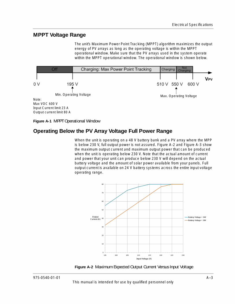
The unit’s Maximum Power Point Tracking (MPPT) algorithm maximizes the output energy of PV arrays as long as the operating voltage is within the MPPT operational window. Make sure that the PV arrays used in the system operate within the MPPT operational window. The operational window is shown below.
Operating Below the PV Array Voltage Full Power Range
When the unit is operating on a 48 V battery bank and a PV array where the MPP is below 230 V, full output power is not assured. Figure A-2 and Figure A-3 show the maximum output current and maximum output power that can be produced when the unit is operating below 230 V. Note that the actual amount of current and power that your unit can produce below 230 V will depend on the actual battery voltage and the amount of solar power available from your panels. Full output current is available on 24 V battery systems across the entire input voltage operating range.
Figure A-1 MPPT Operational Window
Note: Max VOC 600 VInput Current limit 23 A Output current limit 80 A
Min. Operating Voltage Max. Operating Voltage
Figure A-2 Maximum Expected Output Current Versus Input Voltage
50
60
70
80
0
10
20
30
40
195 200 205 210 215 220 225 230
Output Current (A)
Input Voltage (V)
Battery Voltage = 54V
Battery Voltage = 58V
975-0540-01-01 A–3This manual is intended for use by qualified personnel only

Specifications
Default Battery Charger Settings
All settings in the following table are based on a 48 V nominal battery bank. For a 24 V nominal battery bank, divide the voltage values in this table by two.
Figure A-3 Maximum Expected Output Power Versus Input Voltage
5000
4500
5000
3500
4000
2500
3000
Output
2000
2500Power (W) Battery Voltage = 54V
Battery Voltage = 58V
1000
1500
0
500
0
195 200 205 210 215 220 225 230
Input Voltage (V)
Setting
Battery Type
Floodeda
a.When Custom is selected for the battery type, the default settings arebased on the flooded battery type.
Gel AGM
Equalize Voltage 64.0 V n/a n/a
ReCharge Voltage 50.0 V 50.0 V 50.0 V
Bulk Voltage 57.6 V 56.8 V 57.2 V
Absorption Voltage 57.6 V 56.8 V 57.2 V
Float Voltage 54.0 V 55.2 V 53.6 V
Absorption Time 360 min 360 min 360 min
Batt Temp Comp -108 mV/C -108 mV/C -84 mV/C
A–4 975-0540-01-01This manual is intended for use by qualified personnel only

Mechanical Specifications
Mechanical Specifications
Recommended AccessoriesThe Xantrex XW System Control Panel (865-1050) is required for installation of the unit, and it is strongly recommended for continued operation of the unit. It is the primary interface to the unit. It must be used for setup and configuration, and it is recommended to be used for monitoring and fault reporting once installation is complete. Only one Xantrex XW SCP is required to monitor multiple units.
Enclosure Type IP20, indoor, ventilated, aluminum sheet metal chassis with 7/8" and 1" (22.22 mm and 27.76 mm) knockouts and aluminum heat sink
Maximum and Minimum Wire Size in Conduit
#6 AWG to #14 AWG (13.5 to 2.5 mm2)
Maximum and Minimum Wire Size Rating of PV Terminal Block
#6 AWG to #14 AWG (13.5 to 2.5 mm2)
Maximum and Minimum Wire Size Rating of Battery Terminal Block
#2 AWG to #14 AWG (35 to 2.5 mm2)
Wire Size Rating of Auxiliary Output Connector
#16 AWG (1.5 mm2)
Operating Temperature Range (derate above 45 °C)
-20 to +65 °C (-4 to 149 °F)(output power to be derated linearly to zero at 65 °C)
Storage Temperature -40 to +85 °C (-40 to 185 °F)
Altitude Limit (operating) Sea level to 6,500 feet (approximately 2000 m)
Dimensions (H × W × D) 30 × 8 5/8 × 8 5/8" (760 × 220 × 220 mm)
Mounting Vertical wall mount
Weight (Controller only) 29.8 lb (13.5 kg)
Weight (Shipping) 38.3 lb (17.4 kg)
Important: You must use a Xantrex XW SCP with firmware version 1.03.00 or higher for full compatibility with the unit. For information on updating your firmware, contact customer service (see “Contact Information” on page ii). The Xantrex XW Config tool will be required.
975-0540-01-01 A–5This manual is intended for use by qualified personnel only
Specifications
Optional Accessories
Regulatory ApprovalsCertified to UL 1741 and to CSA 107.1 and carries the c(CSA)us mark.
EMC - North America:
• FCC Part-15 sub part B, Class B
• Industry Canada ICES-003, Class B
CE Marked and complies with the following:
Low Voltage Directive 2006/95/EC, per:
• EN50178 Electronic Equipment for Use in Power Installations.
EMC Directive 2004/108/EC, per:
• EN61000-6-3 Emission standard for residential, commercial, and light-industrial environments
• EN61000-6-1 Immunity for residential, commercial, and light-industrial environments
Xantrex Gateway 865-1055
Xantrex Xanbus power supply 865-1057
Xantrex XW Config(Provides the ability to update system firmware and monitor system status. See “Xantrex XW Config User’s Guide” Part Number 975-0365-01-01)
865-1155
A–6 975-0540-01-01This manual is intended for use by qualified personnel only

Index
Aabbreviations ivaccessories
optional A–6recommended A–5
acronyms ivauxiliary output
connections 2–15vent fan application 2–16
Bbatteries
charging current 1–2default charger settings A–4over-current protection 2–11requirements 1–2safety information viiisealed 2–3
battery temperature sensorattaching to battery terminal 2–20installation diagram 2–20installing 2–19overview 2–19using multiple 2–19
Ccables, network 2–17CAUTION, definition ivcharge controlling
charging current 1–2overview 1–2three-stage 1–2two-stage 1–2
charger settingsconfiguring 2–22default A–4
chassis grounding 2–8clearance requirements 2–4commissioning
charger settings 2–22connections 2–22copying settings 2–23multiple units 2–21overview 2–21
setting device number 2–21single unit 2–21
configuringcharger settings 2–22connections 2–22
connectingmultiple PV array strings 2–13multiple units 2–13network cables between multiple units 2–18single unit, floating system 2–13single unit, negative-grounded system 2–12single unit, positive-grounded system 2–13
connections, auxiliary output 2–15copying settings 2–23current rating 2–10
DDANGER, definition iiiDC terminal connector locations 2–9device number, setting 2–21disconnecting the unit 2–16
Eelectrical specifications A–2
FFCC information viiifeatures 1–2floating PV system 2–8fuse holders, ground fault protection 2–8fuses, replacing 3–4
GGateway. See Xantrex Gatewayground fault protection 3–4
fuse holders 2–8normally ungrounded array 3–5overview 2–8replacing fuse 3–4
groundingchassis 2–8PV. See PV grounding
975-0540-01-01 IX-1This manual is intended for use by qualified installers only
Index
Iinstalling battery temperature sensor 2–19interference, radio and television reception viii
Kknockouts
dimensions 2–7locations 2–7overview 2–6removing 2–6
LLexan barrier 2–5limitations on use viilocation
choosing 2–3minimum clearance requirements 2–4
Mmaximum power point tracking voltage range A–3mechanical specifications A–5minimum
clearance requirements 2–4wire gauge 2–10
mountinginstructions 2–7orientation 2–3
MPPT voltage range A–3multiple PV array strings 2–13multiple units
commissioning 2–21connecting 2–13connecting network cables 2–18copying settings 2–23DC wiring diagram 2–15
Nnegative-grounded PV system 2–8network
cables 2–17components 2–17diagram 2–18installation 2–16layout 2–18ordering components 2–17terminators 2–17
normally ungrounded array, ground fault protection 3–5
NOTICE, definition iv
Ooptional accessories A–6ordering network components 2–17over-current protection
battery circuit 2–11PV 2–11requirements 2–11
Ppositive-grounded PV system 2–8power supply, Xantrex Xanbus 2–17PV array
requirements 2–2sizing 2–2
PV disconnect switch 2–11PV grounding
floating 2–8negative 2–8overview 2–8positive 2–8ungrounded 2–8
PV input current rating 2–10
Qqualified personnel, requirements iii
Rradio reception interference viiireception interference viiirecommended accessories A–5regulatory approvals A–6removing
knockouts 2–6wiring compartment cover 2–5
replacing the fuse 3–4requirements, PV array 2–2reverse polarity damage 2–12
Ssafety information
batteries viiigeneral vii
SCP. See Xantrex XW System Control Panelsealed batteries, mounting with 2–3sizing, PV array 2–2specifications
electrical A–2mechanical A–5
IX–2 975-0540-01-01This manual is intended for use by qualified installers only

Index
Ttelevision reception interference viiiterminators, network 2–17three-stage charge controlling 1–2troubleshooting 3–2two-stage charge controlling 1–2
Uungrounded PV system 2–8
WWARNING, definition iiiwire gauge, minimum 2–10wiring
DC terminal connector locations 2–9diagram 2–14
wiring compartmentLexan barrier 2–5removing cover 2–5
XXantrex Gateway 1–2Xantrex Xanbus
network installation 2–16overview 2–16power supply 2–17See also network
Xantrex XW System Control Panel 1–2
975-0540-01-01 IX–3This manual is intended for use by qualified installers only
Index
IX–4 975-0540-01-01This manual is intended for use by qualified installers only

975-0540-01-01
Schneider Electric www.schneider-electric.com
☎ ✉North America 1 650 351 8237
1 866 519 14701 925 245 1022 [email protected]
France 0 825 012 999 [email protected]
Deutschland +49 (0) 180 575 3 575 +49 (0) 2102 404 7101 [email protected]
España +34 902 101 813 +34 933 055 026 [email protected]
L'Italia +39 035 4151111 +39 035415 3200 [email protected]
For other country details please contact your local Schneider Electric Sales Representative or visit our website at:http://www.schneider-electric.com/sites/corporate/en/support/operations/local-operations/local-operations.page.
Printed in India