INSTALLATION AND USE INSTRUCTIONS - jountool.com tools/PSI-C_Manual.pdf · INSTALLATION AND USE...
22
INSTALLATION AND USE INSTRUCTIONS PSI-C Transducerized Pulse Tool Process Controller Important Safeguards For your protection, please read these instructions completely, and keep for future reference. Carefully observe and comply with all warnings, cautions and instructions placed on the equipment or described in this manual. Stanley Assembly Technologies Applications & Productivity Center, 5800 Enterprise Court, Warren, MI 48092-3476 Tel 586-393-1100 Fax 586-393-1200 Toll Free in the US 1-877-787-7830 www.stanleyworks.com PSI-C-0406 © THE STANLEY WORKS, ALL RIGHTS RESERVED
Transcript of INSTALLATION AND USE INSTRUCTIONS - jountool.com tools/PSI-C_Manual.pdf · INSTALLATION AND USE...

INSTALLATION AND USE INSTRUCTIONS PSI-C Transducerized Pulse Tool Process Controller
Important Safeguards
For your protection, please read these instructions completely, and keep for future reference. Carefully observe and comply with all warnings, cautions and instructions placed on the equipment or described in this manual.
Stanley Assembly TechnologiesApplications & Productivity Center, 5800 Enterprise Court,
Warren, MI 48092-3476 Tel 586-393-1100 Fax 586-393-1200 Toll Free in the US 1-877-787-7830 www.stanleyworks.com
PSI-C-0406 © THE STANLEY WORKS, ALL RIGHTS RESERVED

2 PSI-C-0406
Installation and Use
Table of Contents
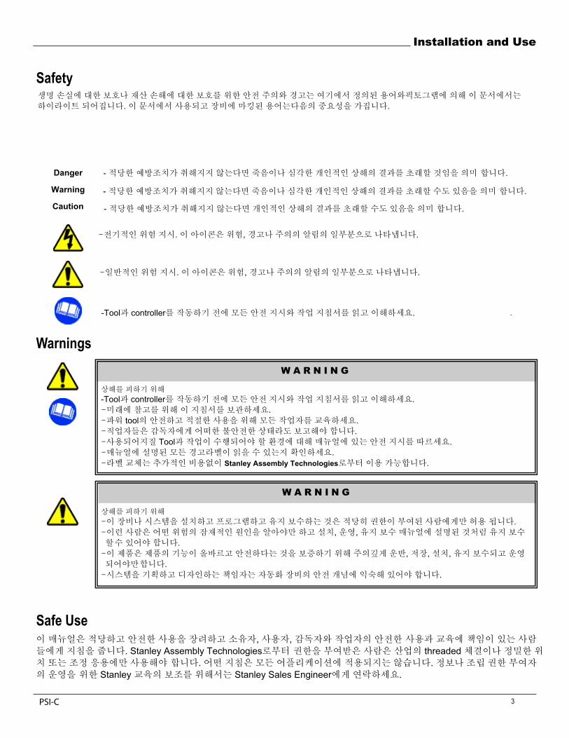
Safety .............................................................................................................................. 3 Symbols and Terms Warnings Safe Use
Introduction and Electrical Safety ............................................................................... 4
Specifications ................................................................................................................ 5
Installation and Air Supply Requirement .................................................................... 6
Tool Compatibility and Transducer Pulse Tools ........................................................ 7
Layout and Operator Interface ..................................................................................... 8
Main Menu and Application Programming.................................................................. 9Parameter Set Up.................................................................................................. 10Test........................................................................................................................ 11
Administration Functions ........................................................................................... 12 Error Proofing OK / NOK ....................................................................................... 13
Normal Operation: Run Mode................................................................................ 13Inputs / Outputs (I/O) ............................................................................................. 14 RJ45 ...................................................................................................................... 15 Networking............................................................................................................. 15 Service and Maintenance ...................................................................................... 15
Troubleshooting and Adjustments ............................................................................ 16
2 PSI-C
Installation and Use
PSI-C-0406 3
Danger -Indicates that death or severe personal injury will result if proper precautions are not taken.
Warning -Indicates that death or severe personal injury may result if proper precautions are not taken.
Caution -Indicates that property damage may result if proper precautions are not taken.
-Indicates an electrical hazard. This icon appears as a part of a Danger, Warning, or Caution notice.
-Indicates a general hazard. This icon appears as a part of a Danger, Warning, or Caution notice.
-Read and understand all the safety recommendations and all operating instructions before operating tools and qualifiers.
Warnings
Safe Use This manual is intended to promote proper and safe use and give guidance to owners, employers, supervisors and others responsible for training and safe use by operators. Qualifiers from Stanley Assembly Technologies are intended for use in industrial threaded fastening or precision position and or adjustment applications only. Some instructions may not apply to all applications. Please contact your Stanley Sales Engineer for information or assistance on Stanley training for assembly Qualifier operation.
W A R N I N G
To Avoid Injury: - Read and understand all the safety recommendations and all operating instructions before operating tools and qualifiers. - Save these instructions for future reference. - Train all operators in the safe and proper use of power tools. - Operators should report any unsafe condition to their supervisor. - Follow all safety recommendations in the manual that apply to the tools being used and the nature of the work being performed.- Verify that all warning labels illustrated in this manual are readable. - Replacement labels are available at no additional cost from Stanley Assembly Technologies.
W A R N I N G
To Avoid Injury: - Only allow suitably qualified personnel to install, program, or maintain this equipment and or system. - These persons must be knowledgeable of any potential sources of danger and maintenance measures as set out in the Installation Operations, and Maintenance manual. - This product must be transported, stored, and installed as intended, and maintained and operated with care to ensure that the product functions correctly and safely. - Persons responsible for system planning and design must be familiar with the safety concepts of automation equipment.
SafetyThe safety notices and warnings for protection against loss of life (the users or service personnel) or for the protection against damage to property are highlighted in this document by the terms and pictograms defined here. The terms used in this document and marked on the equipment itself have the following significance:
. .
-
- .
- .
. , .
. , .
-Tool controller .
-Tool controller ..
tool .합니 .
Tool ..
Stanley Assembly Technologies .
., ,
합니 ., , ,
합니 ..
, ,줍니 . Stanley Assembly Technologies threaded
. . Stanley Stanley Sales Engineer .
PSI-C
4
Installation and Use
W A R N I N G
IntroductionThe ePro FSC Controller provides closed-loop torque control and torque validation (available with date and time stamp). It is easy to program, has common network-ready hardware available and uses industry standard protocols.
The ePro FSC Controller provides precise torque control as well as multiple parameter set capability and poka-yoke error proofing to compatible transducer pulse tools. With the available DTU, up to 2800 fastening cycles are stored, STATISTICS is calculated, DATE/TIME and memory data storage transfer is easy to send to Windows EXCEL.
Compact in design, the ePro FSC Controller provides operator feedback via a large digital display and color LED's for fastener counting, parameter set identification, torque and joint condition status. There are OK / NOK indicator lights for finished cycle or batch evaluation for out-of-spec conditions. Available with four parameter sets allowing different counts and application set-ups, one tool can be set to perform various applications using its full torque range.
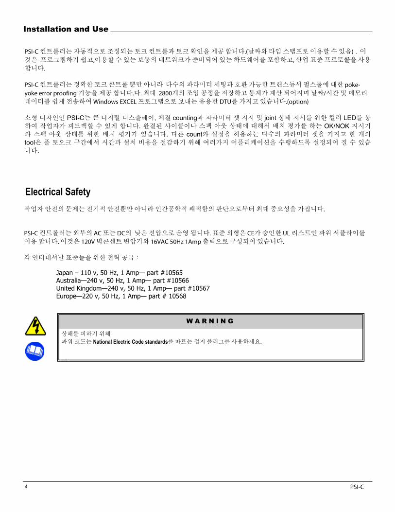
Electrical Safety The issue of operator safety is of maximum importance from both the attitude of ergonomic comfort as well as electrical safety.
The ePro FSC controller operates from low voltage external AC or DC power. The standard configuration utilizes a CE approved power supply that is UL listed. It consists of a wall mount 120VAC transformer with a 16VAC 50 Hz at 1 Amp power output.
Power supplies for other International standards: Japan – 110 v, 50 Hz, 1 Amp— part #10565 Australia—240 v, 50 Hz, 1 Amp— part #10566 United Kingdom—240 v, 50 Hz, 1 Amp— part #10567
Europe—220 v, 50 Hz, 1 Amp— part # 10568
To Avoid Injury: - Plug power cord into a grounded outlet that conforms to National Electric Code standards. - Do not defeat the grounding pin on plug or substitute a cable that does not conform to the power and safety requirements of system.
PSI-C컨트롤러는자동적으로조정되는토크컨트롤과토크확인을제공합니다.(날짜와타임스탬프로이용할수있음).이것은 프로그램하기쉽고,이용할수있는보통의네트워크가준비되어있는하드웨어를포함하고,산업표준프로토콜을사용합니다.
PSI-C컨트롤러는정확한토크콘트롤뿐만아니라 다수의파라미터세팅과호환가능한트랜스듀서펄스툴에대한 poke-yoke error proofing기능을제공합니다.다.최대 2800개의조임공정을저장하고통계가계산되어지며날짜/시간및메모리데이터를쉽게전송하여 Windows EXCEL프로그램으로보내는유용한 DTU를가지고있습니다.(option)
PSI-C , counting joint 컬러 LED. 스팩 아웃 상태에 대해서 배치 평가를 하는 OK/NOK
count 다수의tool
.
작업자안전의문제는전기적안전뿐만아니라인간공학적쾌적함의판단으로부터최대중요성을가집니다.
PSI-C컨트롤러는외부의 AC 또는 DC의 낮은전압으로운영됩니다.표준외형은 CE가승인한 UL 리스트인파워서플라이를이용합니다.이것은 120V 벽콘센트변압기와 16VAC 50Hz 1Amp출력으로구성되어있습니다.
각인터네셔날표준들을위한전력공급:
상해를피하기위해
파워코드는 National Electric Code standards를따르는접지플러그를사용하세요.
PSI-C
Installation and Use
5
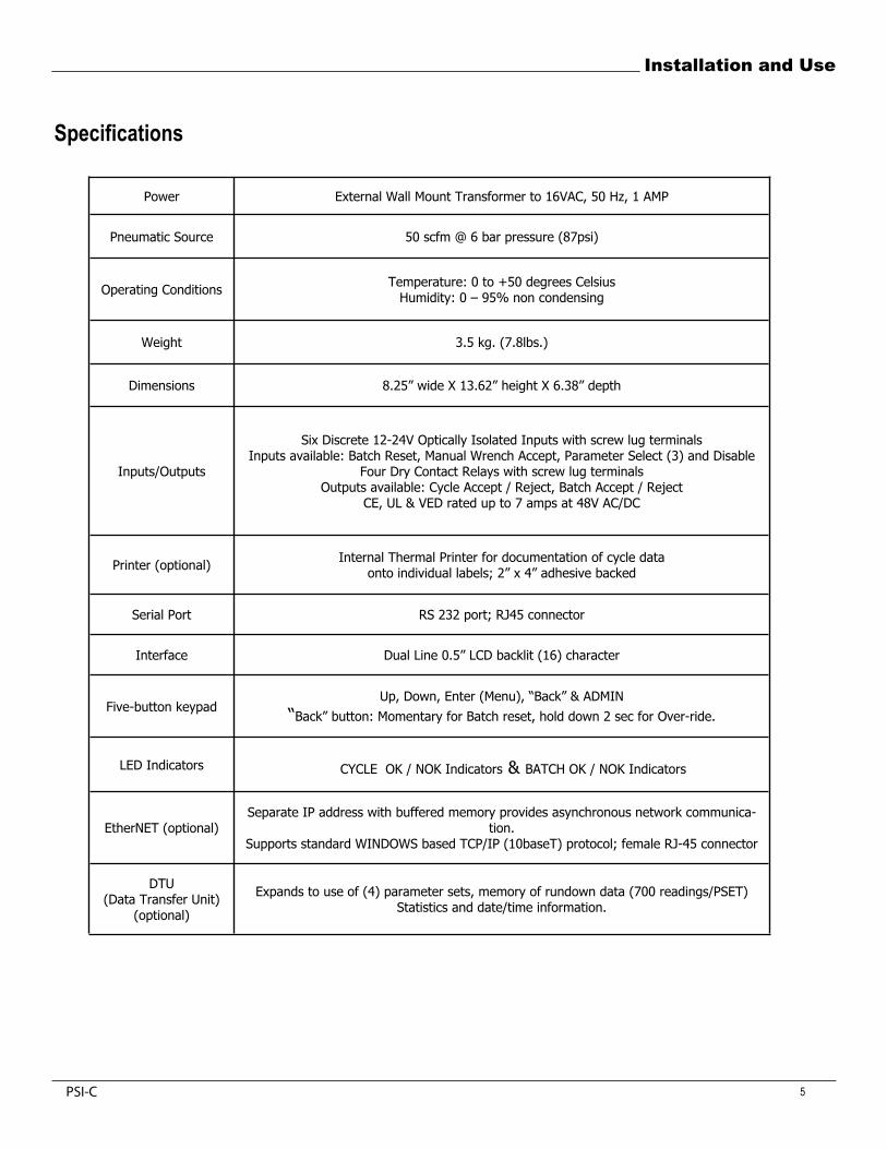
Power External Wall Mount Transformer to 16VAC, 50 Hz, 1 AMP
Pneumatic Source 50 scfm @ 6 bar pressure (87psi)
Operating Conditions Temperature: 0 to +50 degrees CelsiusHumidity: 0 – 95% non condensing
Weight 3.5 kg. (7.8lbs.)
Dimensions 8.25” wide X 13.62” height X 6.38” depth
Inputs/Outputs
Six Discrete 12-24V Optically Isolated Inputs with screw lug terminals Inputs available: Batch Reset, Manual Wrench Accept, Parameter Select (3) and Disable
Four Dry Contact Relays with screw lug terminals Outputs available: Cycle Accept / Reject, Batch Accept / Reject
CE, UL & VED rated up to 7 amps at 48V AC/DC
Printer (optional) Internal Thermal Printer for documentation of cycle data onto individual labels; 2” x 4” adhesive backed
Serial Port RS 232 port; RJ45 connector
Interface Dual Line 0.5” LCD backlit (16) character
Five-button keypad Up, Down, Enter (Menu), “Back” & ADMIN
“Back” button: Momentary for Batch reset, hold down 2 sec for Over-ride.
LED Indicators CYCLE OK / NOK Indicators & BATCH OK / NOK Indicators
EtherNET (optional)Separate IP address with buffered memory provides asynchronous network communica-
tion.Supports standard WINDOWS based TCP/IP (10baseT) protocol; female RJ-45 connector
DTU(Data Transfer Unit)
(optional)
Expands to use of (4) parameter sets, memory of rundown data (700 readings/PSET) Statistics and date/time information.
Specifications
PSI-C
6
Installation and Use
W A R N I N G
To Avoid Injury: - Shutoff valve must be in the closed position until the air lines are installed and properly terminated. - Do not connect power to the ePro FSC Controller until all air line connections are secured. - Supply air energizes the outlet port when electrical power is supplied to the ePro FSC Controller.
Installation and Air Supply Requirement
WWW. SIGMA-SIX.NET
Typical Assembly Line Installation
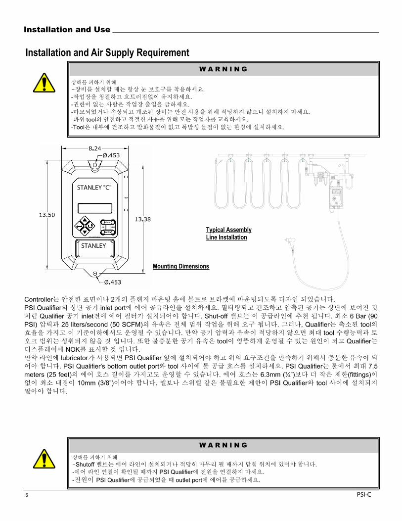
The controller is designed for mounting to a stable surface or bracket by bolting it via the two flanged mounting holes.
In general, the SUPPLY AIR line to power the ePro FSC controller is same line which is sufficient to run the tool being used. A supply of compressed air that is filtered and dry is required. Please check the individual tool specification for air requirements. Most tool specifications are based on 90 psi (6 Bar) for full range operation. However, the controller will operate below at any level as long as the psi and scfm are sufficient for the tool to reach the required torque. The supply air hose should be a ½” (15mm) or 3/8” (10 mm) inside diameter with no restrictions (fittings) smaller than 3/8” inside diameter. If the air pressure and volume are insufficient, the performance of the tool will suffer and the full torque range of the tool will not be realized. If the controller does not receive sufficient air volume, the tool may operate erratically and the controller will indicate a bad cycle or no change on the display.
Install the ePro FSC controller onto an airline with an air filter before the air inlet to the controller. If a lubricator is used, it can be installed before the controller or between the controller and the tool. The lubricator must be a free flowing design and not smallerthan 1/2” NPT. Some lubricators act as a check valve and will not allow air flow “back” thru the lubricator. This type is notrecommended for use with the ePro FSC.
The tool air hose/cable for the EITP, EITM and ESPT series of tools is called the GEMINI. The GEMINI air hose includes an integraltransducer cable and is available in 3/8” I.D., coiled or straight and available in many lengths. A separate transducer cable is also available. Prevent any unnecessary restrictions, elbows, swivels, etc between the controller and the tool to prevent air flow (scfm)restrictions.
W A R N I N G
To Avoid Injury: - Always wear eye protection when installing equipment. - Keep the work area clean and uncluttered. - Keep unauthorized personnel out of the work area. - Do not install worn, damaged, or modified equipment that may be unsuitable for safe use. - Train all operators in the safe and proper use of power tools. - Operators should report any unsafe condition. - Install tools in dry, indoor, non-flammable, and non-explosive environments only.
Mounting Dimensions
.- .- .- .- tool .-Tool .
Controller 2 .PSI Qualifier inlet port .
Qualifier inlet . Shut-off . 6 Bar (90PSI) 25 liters/second (50 SCFM) . , Qualifier tool
. tool. tool Qualifier
NOK .lubricator PSI Qualifier
합니 . PSI Qualifier's bottom outlet port tool . PSI Qualifier 7.5meters (25 feet) . 6.3mm (¼”) (fittings)
10mm (3/8”) 합니 . PSI Qualifier tool합니 .
Shutoff 합니 .- PSI Qualifier .- PSI Qualifier outlet port .
STANLEY "C"
STANLEY
PSI-C
Installation and Use
PSI-C-0406 7
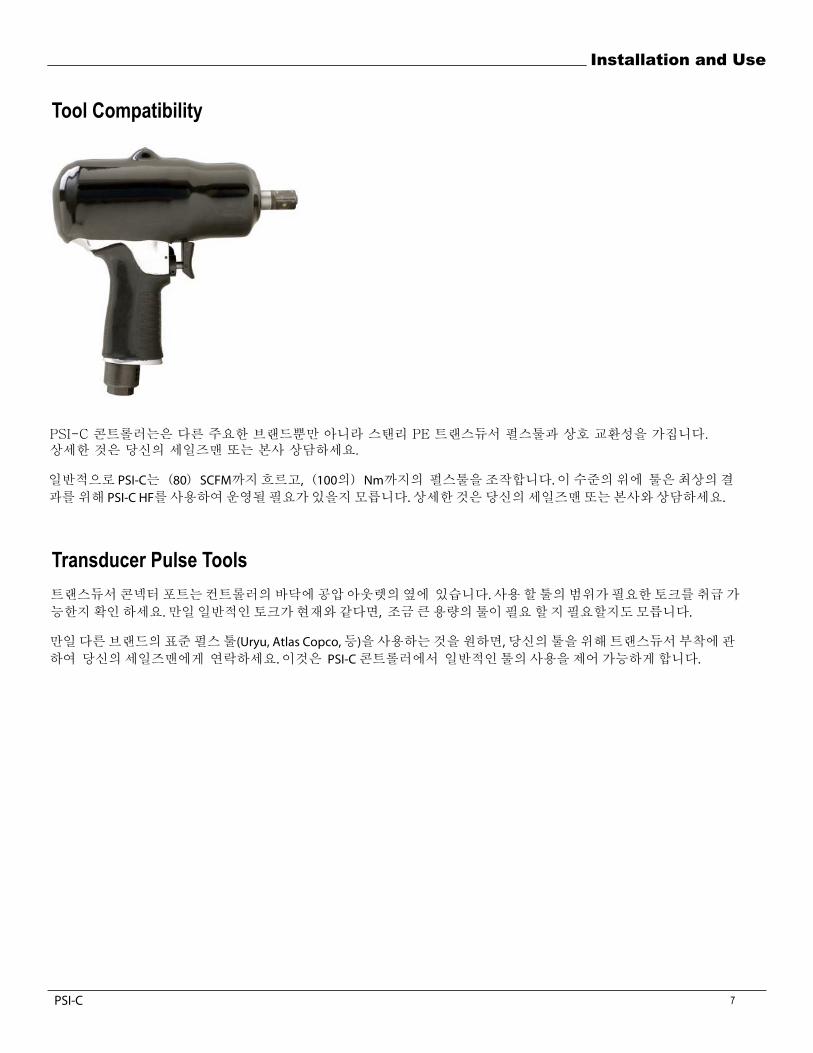
Tool Compatibility
The PSI-C controller is compatible with the Stanley PE transducer pulse tool as well as other major brands. For details, consult your salesman or the factory.
The PSI-C flows up to (80) SCFM and generally operates pulse tools up to (100) Nm. Tools rated over this level may need to be operated using the PSI-C H-F for best results. For details, contact your salesman or the factory.
Transducer Pulse Tools The transducer connector port is at the bottom of the controller next to the air outlet. Make certain that the range of the tool being used is capable of handling the torque required. If prevailing torque is present, then an “over-sized” tool may be required.
If you desire to utilize any other brand of standard pulse tool (Uryu, Atlas Copco, etc), contact your salesperson for a transducerattachment for your tool. This allows use of these common tools to be controlled with the PSI-C process controller.
일반적으로 PSI-C는(80)SCFM까지흐르고,(100의)Nm까지의 펄스툴을조작합니다.이수준의위에 툴은최상의결과를위해 PSI-C HF를사용하여운영될필요가있을지모릅니다.상세한것은당신의세일즈맨또는본사와상담하세요.
트랜스듀서콘넥터포트는컨트롤러의바닥에공압아웃렛의옆에 있습니다.사용할툴의범위가필요한토크를취급가능한지확인하세요.만일일반적인토크가현재와같다면, 조금큰용량의툴이필요할지필요할지도모릅니다.
만일다른브랜드의표준펄스툴(Uryu, Atlas Copco,등)을사용하는것을원하면,당신의툴을위해트랜스듀서부착에관하여 당신의세일즈맨에게 연락하세요.이것은 PSI-C콘트롤러에서 일반적인툴의사용을제어가능하게합니다.
PSI-C

8
Installation and Use
Layout and Operator Interface
AUX RJ-45, REMOTE KEYPAD, LIGHTS, etc
12-24V I/O INPUTS/OUTPUTS
POWER SOCKET (ePro-URYU option)
POWER SOCKET (STD)
3/8” NPT AIR OUTPUT GEMINI HOSE CONNECT
I/O SCHEMATIC
DATA X’FER, NETWORK
SERIAL, ETHERNET or DCX PFCS
1/2” NPT AIR INPUT
TRANSDUCER CABLE CONNECT GEMINI HOSE
PSI-C
Installation and Use
9
1110
20
23
22
4
7
5
19
6
17
9
8
18
13
15
2427
30
32
1
21
3
34 35
12
33
25
29 2826
231
16
36 3738
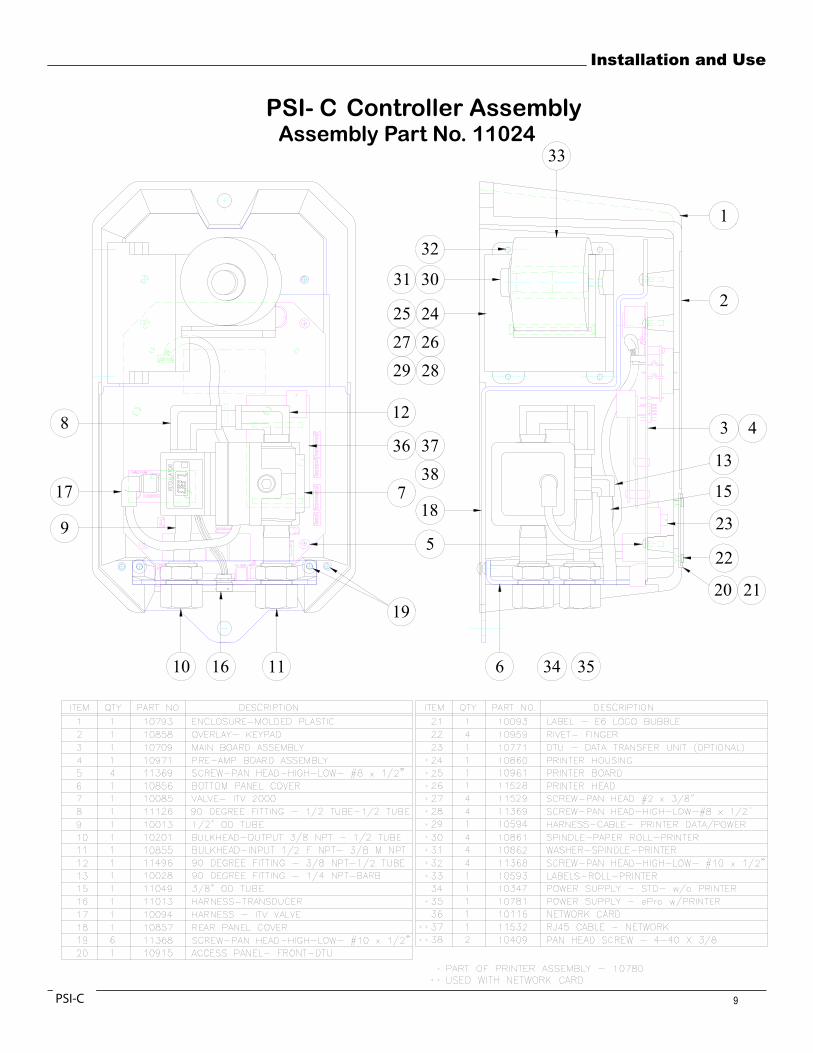
ePro FSC Controller Assembly Assembly Part No. 11024
PSI- C
PSI-C
10
Installation and Use
W A R N I N G
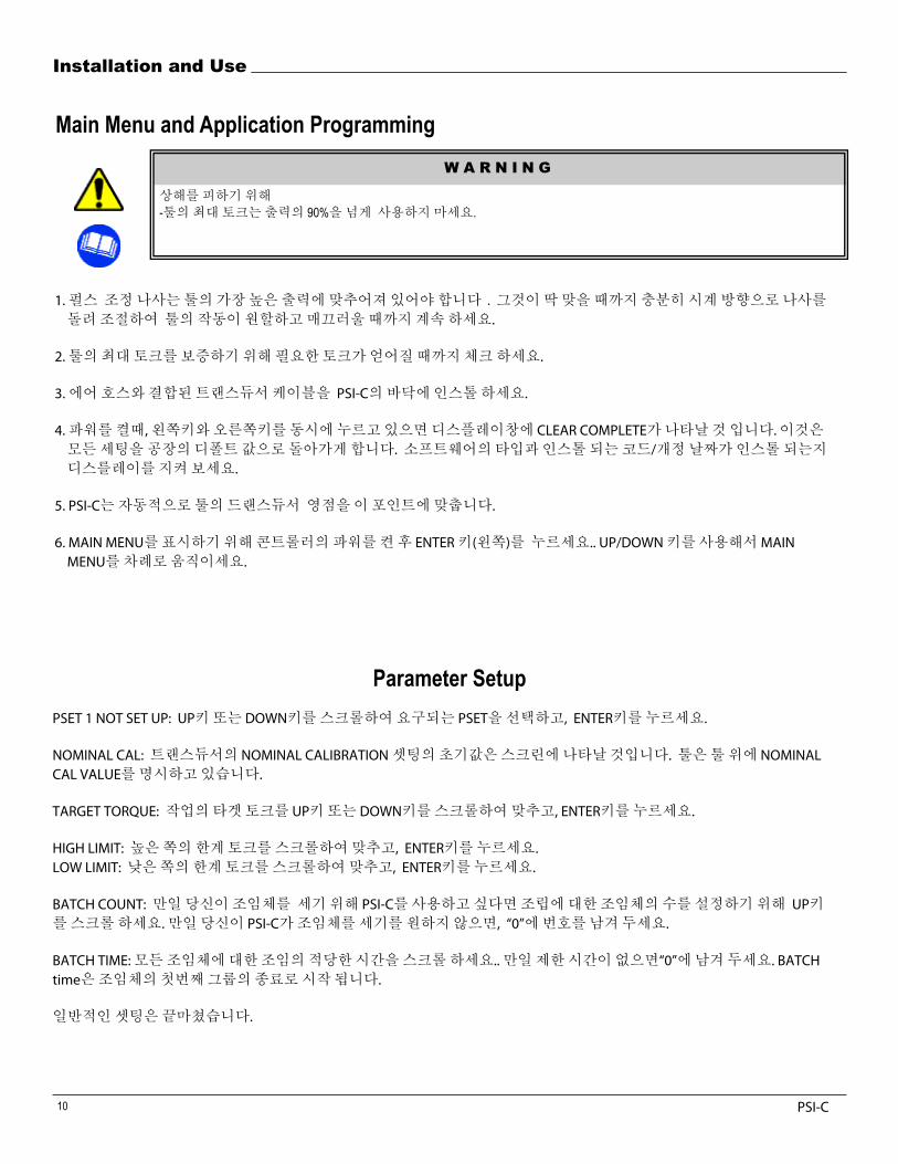
Main Menu and Application Programming
To Avoid Injury: - Do not use the tool higher than 90% of the maximum torque output of the tool.
1. The pulse unit adjustment screw in the tool must be set for the highest output of the tool or at least the HIGH LIMIT of your application. Adjust the screw fully clockwise until it seats; then back it out approximately 1-2 turns or until the operation of the tool is uniform and smooth when pulsing.
2. Check the maximum torque of the tool to insure that it can obtain the torque required.
3. Install and attach the “GEMINI” air hose/transducer cable to the bottom of the ePro and the tool. You may have another versions of air hose and transducer cable depending on your ePro and tool being used.
4. Upon power up, Hold down both the left and right key simultaneous until the display reads CLEAR COMPLETE. This clears all settings back to the factory defaults. Observe the display to determine both the type of software and code/revision date installed.
5. The ePro automatically zeros and checks the tool’s transducer at this point and will show “PSET 1 NOT SET UP”.
6. Press the ENTER key (left key) after power up of the controller to display the MAIN MENU. Use the UP/DOWN key to scroll through the MAIN MENU.
Parameter Setup PSET 1 NOT SET UP: Select the PSET desired by scrolling up or down, press ENTER.
NOMINAL CAL: A default value of the transducer’s nominal calibration setting will appear on screen. The tool will have it’s nominal cal value stated on the tool . If you are using different engineering units than shown, calculate the full scale in units that you require, then scroll up or down to change the value on the screen. Press the ENTER key and the eProautomatically checks and sets the ZERO and MAX values of the transducer connected.
TARGET TORQUE: Enter the target torque of the application by scrolling up or down, press ENTER.
HIGH LIMIT: Scroll to set the upper torque specification, press ENTER. LOW LIMIT: Scroll to set the low limit torque specification, press ENTER.
BATCH COUNT: Scroll up to set the number of fasteners per assembly if you wish to use the ePro to count fasteners. If you do not want the ePro to count fasteners, then leave this number at “0”.
BATCH TIME: Scroll to the number of seconds adequate to tighten all of the fasteners per assembly. Leave this at “0” if there is no time limit. BATCH time starts upon completion of the first in a group of fasteners.You are finished with the general setup.
1.펄스 조정나사는툴의가장높은출력에맞추어져있어야합니다.그것이딱맞을때까지충분히시계방향으로나사를돌려조절하여 툴의작동이원할하고매끄러울때까지계속하세요.
2.툴의최대토크를보증하기위해필요한토크가얻어질때까지체크하세요.
3.에어호스와결합된트랜스듀서케이블을 PSI-C의바닥에인스톨하세요.
4.파워를켤때,왼쪽키와오른쪽키를동시에누르고있으면디스플레이창에 CLEAR COMPLETE가나타날것입니다.이것은모든세팅을공장의디폴트값으로돌아가게합니다. 소프트웨어의타입과인스톨되는코드/개정날짜가인스톨되는지디스를레이를지켜보세요.
5. PSI-C는자동적으로툴의드랜스듀서 영점을이포인트에맞춥니다.
6. MAIN MENU를표시하기위해콘트롤러의파워를켠후 ENTER 키(왼쪽)를 누르세요.. UP/DOWN키를사용해서 MAINMENU를차례로움직이세요.
상해를피하기위해 -툴의최대토크는출력의 90%을넘게 사용하지마세요.
PSET 1 NOT SET UP: UP키또는 DOWN키를스크롤하여요구되는 PSET을선택하고, ENTER키를누르세요.
NOMINAL CAL: 트랜스듀서의 NOMINAL CALIBRATION셋팅의초기값은스크린에나타날것입니다. 툴은툴위에 NOMINAL CAL VALUE를명시하고있습니다.
TARGET TORQUE: 작업의타겟토크를 UP키또는 DOWN키를스크롤하여맞추고, ENTER키를누르세요.
HIGH LIMIT: 높은쪽의한계토크를스크롤하여맞추고, ENTER키를누르세요.LOW LIMIT: 낮은쪽의한계토크를스크롤하여맞추고, ENTER키를누르세요.
BATCH COUNT: 만일당신이조임체를 세기위해 PSI-C를사용하고싶다면조립에대한조임체의수를설정하기위해 UP키를스크롤하세요.만일당신이 PSI-C가조임체를세기를원하지않으면, “0”에번호를남겨두세요.
BATCH TIME:모든조임체에대한조임의적당한시간을스크롤하세요..만일제한시간이없으면“0”에남겨두세요. BATCHtime은조임체의첫번째그룹의종료로시작됩니다.
일반적인셋팅은끝마쳤습니다.
PSI-C

OPERATION FLOWCHART INITIAL SETUP (FSC)
CONTINUED ON NEXT PAGE
---- SIGMASIX LLC---- CLEAR COMPLETE
Holding the “eyes” will Clear and Set Zero
---- SIGMASIX LLC---- 10066.03.16.07
- CAL TRANSDUCER - COMPLETE
- CAL TRANSDUCER - CHECKING CAL
- CAL TRANSDUCER - CHECKING MAX
PARAMETER # 1 NOT SETUP
—- SET TARGET —- TORQUE: 50.0
- NOM CAL VALUE- TQ : 75.0
-- CAL TRANSDUCER -- CHECKING ZERO
-- CAL TRANSDUCER -- CHECKING MAX
-- CAL TRANSDUCER -- COMPLETE
-- SET HI LIMIT -- TORQUE: 57.5
Use the UP / DWN arrows to find the parameter set desired. Press ENTER to select.
Default HI & LO Limits are set to +/- 15% of Torque Target
11PSI-C
PSI-C

OPERATION FLOWCHART INITIAL SETUP (FSC CONT.)
SET BATCH TIMER SECOND(S): 4
SET BATCH COUNT COUNT: 2
TQ: 50.5 PS: 2 CT: 02 TIMER: 004
This is the RUN screen.
-- SET LO LIMIT -- TORQUE: 42.5
12 PSI-C
(PSI-C CONT.)

14
Installation and Use
Test Run a few normal fasteners. The ePro will shut off the tool. Let go of the throttle (the ePro will reset the internal shut-off valve and the tool will turn back on). Check the torque results.
The system is NOT defaulted for REHIT error detection, i.e. re-hitting an already tightened fastener. This feature must be set up through MIN PULSE COUNT in the ADMIN MENU. Please see Administration Functions to set the system up to detect a REHIT fastener and error or display as a fault.
Run the tool in free air and let go of the throttle and the program should ignore the run, display LOW TQ or ABORT. Slip off or strip out a fastener and the display should ignore, error or read SLIP.
If the results obtained are not correct, press ENTER and re-program the application or you can go to the ADMINISTRATION functionsby depressing the hidden button under the ePro logo. Use the BACK key to return.
Administration Functions From the RUN screen, access the Administration functions via the button located under the ePro logo. By quickly pressing the ePro logo, the following options will display. Scroll the functions using the UP and DOWN buttons. NOTE: After adjusting function(s), press ENTER to accept the change, then press the BACK UP key until the run screen appears.
CAL CORRECT: Provides an easy transducer calibration adjustment to an independent system or torque wrench. When using a torque transducer connected to the controller, make a rundown and compare the torque reading from the controller to an independent system. The torque reading from the last rundown appears in the top line of the display as TQ:. By scrolling up or down, enter thevalue from the independent measurement in the bottom line of the display as NEW TQ:. This changes the transducer calibration valueby the percent difference of the two. Future readings should agree with the independent system.
START PSI (ADJUST): This screen allows changes to the tool’s starting PSI level (air pressure). This is called START PSI because the ePro default setting will RAMP up the PSI from this “start” value in order to reach TARGET TQ as quickly as possible.
PRE-TRIGGER: This allows an early shut-off of the tool in order to control any torque “over-shoot” that may occur in certain difficultapplications. Press the ENTER button and two values will appear. The “A” value in the amount of “over-torque” that occurred fromthe last rundown. The “PT” value is the amount of pre-trigger torque you wish to initiate. Scroll UP to set the amount of pre-triggerdesired, then press ENTER to activate this feature.
THRESHOLD: This is the torque setting where the ePro deems that a fastening event has begun. This is automatically set to 30% ofthe TARGET TQ or another pre-determined value. Scroll to alter. Press ENTER to activate change.
PULSE DELAY: The ePro can ignore the initial pulses from the tool. This is required to eliminate any pulse “spiking” from the initialpulse(s). This can happen due to the high free-speed of the tool. This is defaulted to (5) pulses to cover “worst case” applications.
JOINT CONDITION: This feature adds extra pulses to the end of the fastening cycle. This is helpful for applications that may “relax”or lose torque after fastening. PSI is the pressure at which the conditioning will occur. START is the START PSI setting of the ePro. Scroll to the PSI desired for the conditioning. Press ENTER. PULSES will appear. Scroll to set the number of conditioning PULSES. Press ENTER to activate.
DOWNSHIFT: This allows the end of the fastening cycle to be slowed down in order to control torque “over-shoot”. TORQUE will appear when ENTER is pressed showing the TARGET TQ. Scroll down to set the TORQUE at which to initiate DOWNSHIFT. Press ENTER. PSI will appear. Scroll to the PSI level which the tool will run until TARGET TQ is achieved.
MAX PULSE COUNT: This sets a maximum allowable PULSE COUNT before the cycle is REJECTED. If a strip or cross-thread occurs, this can help detect the bad cycle. It can also detect a failing pulse pack unit. Press ENTER and LAST RUN and MAX PULSE CT settingwill appear. The setting can be tested at this point. Watch the screen and run some good and bad cycles. Adjust MAX PULSE CT setting until satisfied. Press ENTER to activate.
MIN PULSE COUNT: This sets a minimum allowable PULSE COUNT before the cycle is REJECTED. If a previous tightened fastener or a cross-thread occurs, this can detect the bad cycle. Press ENTER and pulse counts from the LAST RUN and the MIN PULSE CT settingwill appear. Scroll UP or DOWN to set the MIN PULSE CT. The setting can be tested at this point. Watch the screen and run some good and bad cycles. Adjust MIN PULSE CT setting until satisfied. Press ENTER to activate.
작업스크린으로부터, PSI-C로고의아래에위치하는단추를통해 Administration 기능들에접근하세요. PSI-C로고를빨리 누르는것에의해,아래의옵션들은디스플레이될것입니다. UP키와 DOWN 키를사용하여기능들을스크롤하세요.NOTE:Function(s)를조정하고난후에,변경값을조정하기위해 ENTER키를누른후운용스크린이나타날때까지 BACK UP키를누르세요.CAL CORRECT:독립시스템또는토크렌치에간단한트랜스듀서칼리브레이션교조정을제공합니다.토크트랜스듀서와연결된콘트롤러를사용할때, 콘트롤러에서독립된의시스템까지 Rundown Data를만들고토크를비교합니다.마지막Rundown Data로부터측정된토크값은 TQ로디스플레이에첫번째라인에나타납니다: UP키또는 DOWN키를스크롤하여새로운값을독립된장치로부터디스프레이의맨 밑줄에 NEW TQ를입력합니다. :이것은둘의퍼센트차이에의해트랜스듀서칼리브레이션값을바꿉니다.향후의측정값은독립의시스템과일치해야합니다.START PSI(ADJUST):이스크린은 tool의시작 PSI 레벨(공압)의변경을허용합니다.이것은 START PSI라고불리우는데 PSI-C의초기설정은가능한한빨리 "start" 값에서타겟토크에도달하기위하여 RAMP를설정합니다. PRE-TRIGGER:이것은어려운작업에서발생될지도모르는 "over-shoot" 토크를컨트롤하기위해서빠르게툴의정지를허용합니다. ENTER키를누르세요.그러면 2개의값이나타날것입니다. 마지막런다운에서일어났던 “over-torque”의양이 “A”값입니다. “PT”값은시작하고싶은프리트리거토크의힘의총계입니다.요구되는프리트리거총계를설정하기위해 UP키를누르고이특징을활성화시키려면 ENTER키를누르세요.THRESHHOLD:이것은 PSI-C가조임과정이시작되었다라고간주되는곳의토크셋팅입니다.이것은자동적으로 TARGET TQ의30%또는미리정해놓은다른값에조정됩니다. 스크롤하여바꾸세요.다음단계로변경하려면 ENTER키를누르세요.PULSE DELAY: PSI-C는툴로부터최초의펄스를무시할수있습니다.이것은최초의펄스(s)로부터어떤펄스“spiking”라도제거하는것을요구합니다.이것은도구의높은프리스피드때문에일어날수있습니다.이것은 “최악의경우”작업들을보호하기위해 (5)개의펄스들이실행되지않습니다.JOINT CONDITION:이특징은조임사이클의마지막에여분의펄스를추가합니다. 이것은잠기고난후에 “relax" 하거나조임후에토크를잃을지도모르는공정에도움이됩니다. PSI는조절상태의압력입니다. START는 PSI-C의 START PSI설정입니다.PSI를스크롤하여상태를조정하세요. ENTER키를 누르세요. PULSES가나타날것입니다. PULSES상태의넘버를셋팅하기위해스크롤하세요.다음단계로가려면 ENTER키를누르세요.DOWNSHIFT:이것은조임사이클의마지막에토크를제어하기위하여 “over-shoot” 을느리게하는것을허용합니다.TORQUE는 ENTER키가눌러지면 TARGET TQ가 나타나게될것입니다. DOWNSHIFT를시작하는 TORQUE를설정하기위해DOWN키를스크롤하세요. ENTER키를누르세요. PSI가나타날것입니다. TARGET TQ가나올때까지툴을운용하고 PSI 레벨을스크롤하세요.MAX PULSE COUNT:이것은사이클이거부되기전에최대허용할수있는 PULSE COUNT를설정합니다.만일 strip 또는 cross-thread발생되면,이것은불완전한사이클을찾는것을도울수있습니다.이것은또한결함이있는펄스패키지유닛을찾을수있습니다. ENTER키를누르면마지막공정과최대 PULSE CT셋팅을나타날것입니다.셋팅은이시점에서테스트되어질수있습니다.스크린을보면서유효한사이클과불완전한사이클을운용하세요.만족할때까지 MAX PULSE CT설정을조정하세요.다음단계로가려면 ENTER키를누르세요.MIN PULSE CONUNT: 이것은사이클의이거부되기전에최소허용할수있는 PULSE COUNT를설정합니다.만일이전의확실히조여진조임체또는 cross-thread가발생되면,이것은불완전한사이클을찾는것을도울수있습니다. ENTER키를누르면마지막공정과최소 PULSE CT셋팅이나타날것입니다. UP키와 DOWN키를스크롤하여최소 PULSE CT를설정하세요.셋팅은이시점에서테스트되어질수있습니다.스크린을보면서완전한사이클과불완전한사이클을운용하세요.만족할때까지 MIN PULSE CT설정을조정하세요.다음단계로가려면 ENTER키를누르세요.
Administration Functions
13PSI-C
몇몇개의일반적인조임체를조이세요. PSI-C는툴을정지시킬것입니다.레버를 놓으세요.(PSI-C는내부의셧오프밸브를재셋팅하고툴을되돌려놓을것입니다. ) 토크값을점검하세요.시스템은 REHIT 에러발견을위해초기화되지않을것입니다.즉 re-hitting은이미조임체가조여짐.이특징은 ADMIN MENU에서 MIN PULSE COUNT를통해설정되있어야합니다. REHIT fastener와 에러발견또는오류로인한표시등의시스템셋업은Administration 기능을 참고 하십시요..Free air에서툴을운용하고레버를놓으면 프로그램은툴운용을무시하게되고 LOW TQ또는 ABORT를나타낼것입니다.Slip off또는 Strip out 된조임체는디스플레이에무시되고에러가되며또는 SLIP으로나타납니다.만일얻어지는결과들이정확하지않으면 ,ENTER를 누르고재프로그램하거나그렇지않으면 아래에서숨겨졌던단추를눌러 ADMINISTRATION 기능에들에갈수있습니다.되돌아가려면 BACK 키를사용하세요.

Installation and Use
15
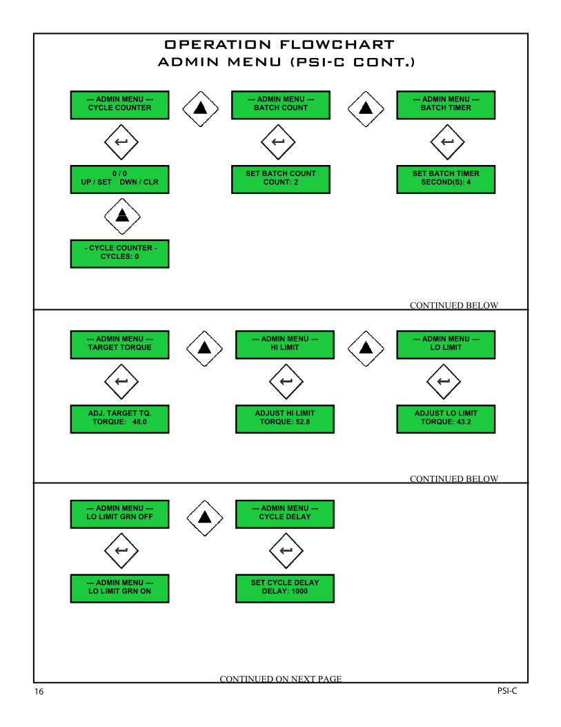
Administration Functions (cont’d)CYCLE COUNTER: This allows a maintenance cycle counter to be set that will count down from a selectable number of cycles. Once this number of cycles is achieved a MAINTENACE REQUIRED screen appears so that normal pulse tool maintenance can be per-formed. Press Enter and UP/SET, DWN/CLEAR appears. Press UP and CYCLES will appear. Scroll UP to set the number of cycles to count.
BATCH COUNT: Press ENTER to adjust the BATCH COUNT or the total fasteners to be run successfully on the part. Press ENTER and scroll UP or DOWN to alter the fastener COUNT per BATCH.
BATCH TIMER: Press ENTER to adjust the BATCH TIME or the total cycle time for all fasteners to be run successfully on the part. Zero is equal to OFF or no timer. Press ENTER and scroll UP or DOWN to alter the number of SECONDS allowed for the BATCH. If all fas-teners are not successfully tightened in the allotted time, a Batch NOK occurs.
TARGET TORQUE / HI LIMIT / LOW LIMIT: Adjust the torque target, high or low limit if the specification changes.
LOW LIMIT GRN ON: Use the ENTER button to toggle ON/OFF whether the green (OK) LED light turns ON after the LOW LIMIT is crossed. If OFF is chosen, the green LED will come on when TARGET TQ is achieved. Scroll to the next ADMIN function. Press the BACK button to return to the RUN screen. TIME/DATE: Adjust the TIME and DATE accordingly.
CYCLE DELAY: This setting determines the off time between the end of one run-down and tool reset for the next cycle. The total range of adjustment is between 10 and 1000 counts. This relates to .25 second to 4 seconds of off time. The default value of 100 will keep the tool off for about one half second before allowing the operator to press the trigger for the next fastener. If this is too slow, adjust (by using the UP/DWN buttons) the value down to approximately 60-80. Any lower may be too quick and may not allow the operator enough time to release the trigger. A higher value causes the tool to reset slower.
TIME/DATE: Sets TIME and DATE. Press UP to SET. Scroll to change. Press ENTER. Press DOWN to exit.
STATS: Press ENTER. Scroll UP or DOWN to select SAMPLE SIZE. Press ENTER to view CP, CPK. Press ENTER again to view MEAN, RANGE, and press ENTER again to see MIN and MAX readings. Press BACK UP key to EXIT.
DATA: allows the download of all data stored on optional DTU (Data Transfer Unit). Press ENTER. Press DOWN to download all RS232serial data through RJ45 serial port. Press UP to CLEAR all DATA.
I/O (Latched or Momentary): Allows the outputs to be latched until the next cycle starts, or momentary which turns the outputs off 2 seconds after the completion of the cycle. Toggle by pressing ENTER. Scroll UP or DOWN to move to the next option.
P-SET LOCK OUT: Activating this option locks out the parameter keys from the operator. This prevents the ePro from being switchedto a parameter set that is not set up. Press ENTER to lock and ENTER again to un-lock. Scroll to move on.
PROGRAM LOCK OUT: Activating this option locks out the program keys from the operator allowing only PSET selection and Batch Clear. Press ENTER to lock and ENTER again to un-lock. Scroll to move on to the next option.
ADMIN LOCK ON/OFF: Initially turning this feature ON will allow the entry of a four button code using the existing four keys in a pro-grammable order. Once this is done, this programmed button order must be entered every time the ADMIN MENU is accessed through the hidden ePro button. Turning this OFF will allow entry to the ADMIN MENU without a four button code.
FILTER: Sets the FILTER Frequency for the transducer circuit. Default is FREQ=1150.
EtherNET: Allows entry of the UNIT IP ADDRESS. Scroll UP or DOWN to change. Press ENTER.
PRETORQUE: Allows the setup of a two-step fastening procedure. This is used for wheels, cylinder heads or any assembly may re-quire a “snug” torque before a “final” torque to compensate for relaxation. Press ENTER. Scroll UP to choose PRETORQUE. This isusually 50-60% of the specified “final” torque. Press ENTER. Note: BATCH COUNT must be programmed for correct sequencing. The “Run Screen” will now show “PTQ” when running the PRETORQUE or “snug” torque. PRETORQUE all fasteners. When PRETORQUE BATCH is finished “OK”. The “Run Screen” will change to show “TQ”. Final Torque all fasteners. Note: MIN PULSE COUNT may need to be adjusted to accept final torque, while still rejecting a REHIT fastener.
RAMP SPEED: HIGH, MED, LOW can be chosen to set the RAMP SPEED of the air pressure from the START PSI. The START PSI de-fault value is 70 PSI. This is to control the rundown speed and prevent torque scatter. When the tool “runs” a fastener, the PSI is RAMPED up to maximum PSI until the TARGET TQ is achieved. The speed at which this PSI is increased is selectable. Toggle with theENTER button to choose. Scroll to the next ADMIN function. Press the BACK button to return to the RUN screen.
CYCLE COUNTER: 이것은 메인터넌스 사이클 카운터를 선택 가능한 수의 사이클로부터로 세어 나갈것인가를 셋팅하는 것을 허용합니다. 이 사이클의 수가 실행되어 지면 노멀 펄스 툴의 메인터넌스가 실행 될 수 있게, 스크린에 MAINTENACE REQUIRED가 나타납니다.Enter키를 누르면 UP/SET, DWN/CLEAR가 나타납니다. UP키를 누르면 사이클이 나타날 것 입니다. 사이클 수의 카운트를 설정하기 위해 UP키를 누르세요..BATCH COUNT: BATCH COUNT를 조정하거나 파트에서 총 조임이 성공적으로 운영되었는지를 알기 위해 ENTER키를 누르세요. ENTER키를 누르고 UP키와 DOWN키를 스크롤하여 BATCH당 조임 카운트를 바꾸세요.BATCH TIMER: BATCH TIME를 조정하거나 파트에서 모든 조임이 성공적으로 운영되기 위한 총 사이클 타임을 알기 위해 ENTER키를누르세요. 제로는 OFF 또는 타이머가 없는 것과 같습니다. ENTER키를 누르고 BATCH를 위한 시간의 바꿈을 허용하려면 UP키와 DOWN키를 스크롤 하세요. 만일 모든 조임체가 지정된 시간안에 성공적으로 조여지지 않았다면, Batch NOK가 나타날 것 입니다.TARGET TORQUE / HI LIMIT / LOW LIMIT: 만일 세부 항목이 바뀌면 target torque, high limit, low limit을 조정하세요.LOW LIMIT GRN ON: LOW LIMIT이 교차된 후에 녹색의(OK의) LED 라이트가 켜짐에 관계없이 ON/OFF를 바꾸기 위해 ENTER키를 사용하세요. 만약 OFF가 선택되면, TARGET TQ가 이뤄질 때 녹색 LED가 켜질 것입니다. 다음 ADMIN 기능을 위해 스크롤 하세요. BACK키를누르면 운용 스크린으로 돌아갈 것 입니다. TIME/DATE:TIME과 DATE를 조정 하세요.CYCLE DELAY: 이 설정은 다음 사이클을 위해 마지막 1개의 런다운 데이터와 툴 리셋 사이에 off time을 결정합니다. 조정의 총 범위는10과 1000 카운트 사이에 있습니다. 이것은 0.25초에서 4초간의 off time과 관련이 있습니다. 초기값 100은 작업자가 다음 조임을 위해트리거를 누르는 것을 허용하기 전에 약 1.5초동안 툴을 멈출 것 입니다. 만일 이것이 너무 느리면 설정값을 대략 60-80으로 조정하세요.(UP/DWNO키를 사용하여) 낮은 설정은 너무 빠를지도 모르고 툴을 운용 할 작업자에게 충분한 시간을 허용하지 않을지도 모릅니다. 높은 설정값은 툴을 느리게 재설정 할 수 있습니다.TIME/DATE: TIME과 DATE를 셋팅 하세요. UP키를 누르면 설정 됩니다. 스크롤하여 바꾸세요. ENTER키를 누르세요. DOWN키를 누르면 돌아 갑니다.STATS: ENTER키를 누르세요. SAMPLE SIZE를 선택하기 위해 UP키 또는 DOWN키를 스크롤 하세요. CP, CPK를 보기 위해 ENTER키를누르세요. ENTER키를 다시 누르면 MEAN, RANGE를 볼 수 있고, 또 ENTER키를 누르면 MIN와 MAX의 값을 볼 수 있습니다. BACK UP키를 누르면 돌아 갑니다.DATA: 옵션의 DTU(DATA Transfer Unit)는 저장된 모든 데이터의 다운로드를 허용 합니다. ENTER키를 누르세요. RJ45 시리얼 포트를통해 모든 RS232 시리얼 데이터를 다운로드하기 위해 DOWN키를 누르세요. UP키를 누르면 모든 데이터는 지워 집니다.I/O (Latched or Momentary): 다음 사이클의 시작까지 output을 래치 시키거나 작업 완료 후에 순간적으로 output을 2초 동안 정지 시킵니다. ENTER키를 누르면 토글 됩니다. 다른 옵션으로 이동하기 위해 UP키 또는 DOWN키를 누르세요.P-SET LOCK OUT: 이 옵션은 작업자로부터 파라미터 키로 들어가지 못하게 합니다. 이것은 PSI-C가 셋팅되지 않는 파라미터를 새로 바꾸게 되는 것을 방지 합니다. ENTER키를 누르면 파라미터는 잠기고 다시 ENTER키에 누르면 해제 됩니다. 다음 단계로 가려면 스크롤하세요.PROGRAM LOCK OUT:이 옵션은 작업자로부터 PSET 선택과 Batch Clear만을 허락하고 프로그램 키로 들어가지 못하게 합니다. ENTER키를 누르면 잠기고 ENTER키를 다시 누르면 해제 됩니다. 다음 옵션으로 가기 위해 스크롤 하세요.ADMIN LOCK ON/OFF: 초기에 이 특징을 켜는 것은 프로그램의 명령에서 기존의 4개의 키들를 사용하고 있는 4개의 버튼 코드의 입장을허락 할 것입니다. 이것이 하게 되면,ADMIN MENU가 숨겨졌던 PSI-C버튼을를 통해 접근 될 때마다, 이 프로그램 되었던 버튼 명령을넣어야 합니다. 이것을 끄게 되면 4개의 버튼 코드없이 ADMIN MENU에 입장을 허용 할 것 입니다.FILTER: 트랜스듀서 회로를 위한 FILTER Frequency를 설정합니다. Default는 FREQ=1150입니다.EtherNET: 본체 IP ADDRESS의 입장을 허용 합니다. UP키 또는 DOWN키를 스크롤하여 변경 하세요. ENTER키를 누르세요.PRETORQUE: two-step의 조임 과정의 셋팅을 허용 합니다.이것은 휠, 실린더 헤드 또는 어떤 조립이든 "final" 토크 전에 응력 완화를 위한 보정인 "snug" 토크가 요구 될때 사용 됩니다. ENTER키를 누르세요. PRETORQUE를 선택하기 위해 UP키를 스크롤 하세요. 이것은 보통 설정된 “final”토크의 50-60%입니다. ENTER키를 누르세요. Note: 올바른 시권스를 위해 BATCH COUNT는 프로그램 되어야 합니다.PRETORQUE가 실행되거나 "snug" 토크가 시행될 때 "Run Screen"은 표시 되지 않을 것입니다. 모든PRETORQUE 조임 .PRETORQUEBATCH가 끝나면 “OK. “TQ”를 나타내는 “Run Screen"은 변경 될 것 입니다. Final Torque의 모든 조임. Note: REHIT 조임이 거부되는 동안 MIN PULSE COUNT는 final토크를 받기 위해서 조절 될 필요가 있을지도 모릅니다.RAMP SPEED: HIGH, MED, LOW는 START PSI로부터 공압 램프 스피드의 셋팅을 선택 되어질 수 있습니다. START PSI 디폴트값은 70 PSI입니다. 이것은 런다운 스피드를 제어하고, 토크의 분산을 방지한다. 툴이 조임을 “RUN” 할 때,TARGET TQ가 도달 할 때까지 PSI는최대 PSI까지 RAMPED될 것입니다. 스피드는 PSI가 증가함으로써 선택 가능 합니다. 다음 ADMIN 기능으로 가기 위해 스크롤 하세요..BACK키를 누르면 RUN 스크린으로 복귀 할 것 입니다.
14 PSI-C

OPERATION FLOWCHART ADMIN MENU (FSC)
CONTINUED ON NEXT PAGE
CONTINUED BELOW
ADJUST THRESHOLD TORQUE: 7.5
--- ADMIN MENU --- THRESHOLD
--- ADMIN MENU --- JOINT CONDITION
--- ADMIN MENU --- CAL CORRECT
--- CAL CORRECT --- UP/MAN. DWN/AUTO
JOINT CONDITION PSI: 00 START: 65
—-START PSI —- PSI: 50
--- ADMIN MENU --- START PSI
--- ADMIN MENU --- DOWNSHIFT
--- DOWNSHIFT --- TORQUE: 50.0
JOINT CONDITION PULSES: 0
ADJUST DOWNSHIFT PSI: 35 START: 50
DYN TQ: 0.0 STATIC TQ: 0.0
--- CAL CORRECT --- CAL: 200.0
CONTINUED BELOW
—-PULSE DELAY —- PULSE(S): 5
--- ADMIN MENU --- PULSE DELAY
—-PRETRIGGER —- PT: 00.0 A: -00.0
--- ADMIN MENU --- PRETRIGGER
--- ADMIN MENU --- MAX PULSE COUNT
LAST RUN: 32 MAX PULSES: 200
--- ADMIN MENU --- MIN PULSE COUNT
LAST RUN: 37 MIN PULSES: 10
15PSI-C
(PSI-C)
--- ADMIN MENU --- TARGET TORQUE
ADJ. TARGET TQ. TORQUE: 48.0
--- ADMIN MENU --- LO LIMIT GRN OFF
--- ADMIN MENU --- LO LIMIT GRN ON
OPERATION FLOWCHART ADMIN MENU (FSC CONT.)
CONTINUED BELOW
0 / 0 UP / SET DWN / CLR
--- ADMIN MENU --- CYCLE COUNTER
- CYCLE COUNTER - CYCLES: 0
--- ADMIN MENU --- BATCH COUNT
SET BATCH COUNT COUNT: 2
SET BATCH TIMER SECOND(S): 4
--- ADMIN MENU --- BATCH TIMER
--- ADMIN MENU --- LO LIMIT
ADJUST LO LIMIT TORQUE: 43.2
ADJUST HI LIMIT TORQUE: 52.8
--- ADMIN MENU --- HI LIMIT
CONTINUED BELOW
--- ADMIN MENU --- CYCLE DELAY
SET CYCLE DELAY DELAY: 1000
CONTINUED ON NEXT PAGE 16 PSI-C
(PSI-C CONT.)

—- ADMIN MENU —- I/O (MOMENTARY)
--- ADMIN MENU --- I/O (LATCHED)
OPERATION FLOWCHART ADMIN MENU (FSC CONT.)
--- ADMIN MENU --- TIME / DATE
03-08-07 01:49 UP / SET DWN / EXIT
- SET TIME / DATE - MONTH: 03
- SET TIME / DATE - DAY: 08
- SET TIME / DATE - YEAR: 07
CONTINUED ON NEXT PAGE
--- ADMIN MENU --- STATS
----- STATS ---- SAMPLES < 10
---- DATA ---- UP/CLR DWN/DWNLOAD
--- ADMIN MENU --- DATA
---- DATA ---- 28,800 8 N 1
---- DATA ---- DATA CLEARED
CONTINUED BELOW
17PSI-C
(PSI-C CONT.)

CONTINUED BELOW
--- ADMIN MENU --- PRGM LOCKOUT OFF
--- ADMIN MENU --- PSET LOCKOUT OFF
--- ADMIN MENU --- PSET LOCKOUT ON
--- ADMIN MENU --- PRGM LOCKOUT ON
--- ADMIN MENU --- PRETORQUE
--- PRETORQUE --- TQ: 0.0
--- PRETORQUE —- THOLD: 0.0
—- PRETORQUE —- PSI: 50.0
--- ADMIN MENU --- ADMIN LOCK OFF
LEARN ADMIN CODE CODE: * * * *
--- ADMIN MENU --- RAMP SPEED MED
--- ADMIN MENU --- RAMP SPEED HI
--- ADMIN MENU --- FILTER
SET FILTER FREQ FREQ: 1150
--- ADMIN MENU --- RAMP SPEED LOW
UNIT IP ADDRESS 192.
--- ADMIN MENU --- ETHERNET
OPERATION FLOWCHART ADMIN MENU (FSC CONT.)
CONTINUED BELOW
--- ADMIN MENU --- RAMP SPEED OFF
18 PSI-C
(PSI-C CONT.)

20
Installation and Use
Error proofing is one of the most important features of the eProFSC controller. Once an application has been set-up, the ePro controls the torque applied and discerns between a fastening cycle PASS and the following errors:
LOW TORQUE or Short Cycle: If the tool has run many cycles and the pulse oil or the air motor needs maintenance, the tool may notbe able to reach torque. Also the operator may be stopping the cycle prior to completion of the fastening to TARGET TQ. This sometimes occurs when the operator anticipates the end of cycle and releases the throttle trigger prematurely (before the ePro controller has shut-off the tool). If LOW LIMIT GRN ON is chosen in the ADMIN MENU and the operator lets go of the throttle afterthe LOW LIMIT has been passed, then a PASS will result, even though TARGET TORQUE has not been achieved.
HIGH TORQUE: This can occur if the joint conditions change to a harder type joint than what was the original or the PSI has beenadjusted to increase the speed of the tool beyond what can be controlled consistently on the application. This can also occur if the CAL VALUE is incorrect.
RE-HIT: This occurs whenever the tool is applied to a pre-tightened fastener. This is not a defaulted error condition. It must be set up through the MIN PULSE COUNT in the ADMIN MENU. Once set up correctly an NOK will be displayed when the tool is cycled on a previously tightened fastener. If a REHIT is accepted, the MIN PULSE COUNT feature should be adjusted.
MIN PULSE COUNT: If a MIN number of PULSES is not achieved before TARGET TORQUE is reached, an error will occur. Once set up correctly, if a previous tightened fastener or a cross-thread occurs, a NOK will result. The system default is “0” pulse counts, which means all rundowns which result in a final torque between LOW LIMIT and HIGH LIMIT will be OK.
MAX PULSE COUNT: If a strip or cross-thread occurs, this can cause too many pulses and the bad cycle. This error can also occur if the pulse pack in the tool is in need of service or failing.
Slip-off (or cam out): If the socket or screwdriver bit slips off the fastener, the controller will not count the cycle or alarm this condition as TQ LOW if the THRESHOLD has not been crossed.
Short cycle (premature cycle abort): This feature insures that only attempts to tighten fasteners are counted. The controller will not count the cycle or alarm this condition as TQ LOW if the THRESHOLD has not been crossed.
NOTE: The eProFSC ignores free air running of the tool unless THRESHOLD is crossed.
Error Proofing OK / NOK
Normal Operation: Run Mode
When operating in the RUN mode, the UP/ DOWN keys allow the operator to change between parameter sets, unless the PSET LOCK OUT is activated. PSET LOCK OUT is recommended when only one PSET is being utilized.
Pressing the BACK button clears the batch. The BATCH NOK output fires and turns on the red BATCH LED.
Pressing and holding the BACK button for 1-2 seconds puts the ePro in “OVER-RIDE” mode. OVER-RIDE means that the system has full power without any torque control or shut-off capabilities.
The ePro has a two line main display. This shows the final TORQUE, Parameter or PSET, the BATCH or fastener COUNT and the BATCH TIMER. BATCH COUNT represents the number of fasteners that the ePro has been programmed to count (per BATCH). LED’s will change to GREEN upon reaching an OK or GOOD fastening cycle. Outputs and CYCLE lights on the tool, if applicable, fire automatically. CYCLE lights on the tool can be fired after crossing the LOW LIMIT or when TARGET TORQUE is achieved.
The BATCH light on the ePro and internal outputs also fire automatically. Running the next cycle clears and resets these lights and outputs automatically. By selecting I/O MOMENTARY from the ADMIN MENU will clear the cycle lights and the outputs after 2 seconds.
에러 프뤼핑은 PSI-C 컨트롤러에서 가장 중요한 기능 중 하나입니다. 일단 장비가 셋업되면, PSI-C는 적용된 토크를 조정 하고 조임 사이클 통과와 다음의 에러에서 구별 됩니다.
Low 토크나 Short Cycle : 툴을 너무 오래 사용하고 또 펄스 오일이나 에어 모터가 유지 보수를 필요로 하게 되고, 작업시 목표 토크값에 도달하지 않을 것 입니다. 또한 작업자가 조임작업이 끝나기 전에 사이클 완료가 될지 모릅니다. 이러한 경우에 작업자가 작업이 끝나기 전에 트리거를 미리 놓는 현상이 일어나곤 합니다. Low Limit GRN ON이 ADMIN Menu에서 선택되고 작업자에게 LOW LIMIT 통과가 발생되고 있으면, 타겟 토크에 도달 하지 않았음에도 불구하고 PASS는 결과값을 보여줄 것입니다.
High Torque : High Torque는 조인트의 상태가 원래의 조인트 보다 강한 조인트 타입으로 변경 되거나, PSI가 조절 할 수 있는 속도 이상으로 조정 되었을때 때 발생됩니다. 이러한 현상은 또한 CAL값이 부정확 할 때에도 발생합니다.
Re-Hit : Re-Hit는 툴이 미리 조여진 조임체에 적용될때는 언제나 발생합니다. 이것은 기본 에러 컨디션은 아니고, Admin Menu의 Min Pulse Count를 통해 셋업해야 합니다. 일단 정확하게 셋업되면 NOK는 툴이 이전에 조여진 조임체에서 작업될 때 나타날 것 입니다. Rehit이 받아 들여지면, Min Pulse Count기능은 적용 될 것 입니다.
Max Pulse Count : 스트립이거나 Cross-thread가 발생하면, 이것은 굉장히 많은 pulse와 bad cycle를 야기 합니다. 이러한 에러는 툴 내의 펄스 팩이 서비스의 필요하거나 실패에 있다면 또한 발생할 것입니다.
Slip-off(or cam out) : 소켓이나 스크루 드라이버 비트가 조임체에서 미끄러져 빠지면, 컨트롤러는 사이클을 카운트 하지 않거나, 이러한 상태를 Threshold가 교차되지 않는 다면 TQ LOW로써 경고 할 것 입니다.
Short Cycle(Premature cycle abort) : 이 기능은 조임체를 조인 시도만 카운트 한다는 것을 보증 합니다. 컨트롤러는 Threshold가 교차하지 않을 경우에 사이클을 카운트 하지 않거나 TQ LOW로 이 조건을 경고 할 것입니다.
NOTE : PSI-C는 Threshold가 교차되지 않으면 툴의 공회전을 무시 합니다.
Run모드에서 작업할때 UP/DOWN키는 작업자가 파라미터셋을 변경하는 하는 것을 가능하게 합니l다. PSET LOCK OUT가 실행되지 않는 다면 PSET LOCK OUT는 하나의 PSET이 사용될 때 권장 됩니다.
배치를 지우기 위해 BACK버튼을 누르세요. BATCH NOK는 fire를 출력하고 빨간색 BATCH LED를 켭니다.
1~2초 동안 BACK버튼을 누르고 있으면 PSI-C는 OVER-RIDE모드가 됩니다. OVER-RIDE는 시스템이 어떠한 토크 컨트롤 없이 full power를 가지거나 가능 출력을 차단하는 것을 의미 합니다.
PSI-C는 두줄의 메인 디스플레이를 가집니다. 이것은 최종 토크값, 파라미터나 PSET, Batch나 조임 카운트와 Batch Timer을 보여 줍니다. Batch Count는 PSI-C가 Batch 하나 하나를 카운트 하기 위해 프로그램된 조임의 숫자를 나타냅니다. LED는 OK나 GOOD fastening cycle로 도달 했다는 Green색을 나타냅니다.
19PSI-C
Min Pulse Count : Pulse의 최소 값은 타겟 토크값이 도하기전에 도달되지 않는다면, 에러가 발생 할 것 입니다. 일단 정확하게 셋업되면 이전에 조여진 조임이나 Cross-thread가 발생하면 NOK가 결과로 나타날 것 입니다. 시스템 디펄트는 0 펄스 카운트입니다.

Installation and Use
21
INPUTS / OUTPUTS (I/O)
OUTPUTSOutput signal lines are switched by closing normally open relay contacts. These relays conform with VDE0435, UL508 and CSA22.2. Signal power is customer supplied and may be AC or DC up to 48 volts. The maximum current capacity of the relay circuitry is 7 amps per contact with 7 amps total.
INPUTSInputs are optically decoupled from other circuitry. These signals must be between 12 & 24 volts DC. The design will accept DC input signals of either polarity.
I/O SCHEMATIC
OUTPUTS
PIN #1 = COMMON
PIN #2 = CYCLE OK
PIN #3 = CYCLE NOK
PIN #4 = BATCH OK
PIN #5 = BATCH NOK
INPUTS
PIN #6 = DISABLE TOOL
PIN #7 = BATCH REJECT / RESET
PIN #8 = MANUAL WRENCH ACCEPT
PIN #9 = PSET BIT-3 } BINARY
PIN #10 = PSET BIT-2 } PARAMETER
PIN #11 = PSET BIT-1 } SELECT
PIN #12 = INPUT COMMON
I/O CONNECTOR PLUG (OPTIONAL): PART # 11424
BA
TC
H
DIS
AB
LE
BA
TC
H
BA
TC
H
121110987654321
0 0 1=PS10 1 0=PS20 1 1=PS31 0 0=PS4
CY
CLE
CY
CLE
출력시그널라인은통상오픈릴레이접점을닫는것에의해연결됩니다.이릴레이들은 VDE0435, UL508과 CSA22.2에들어맞습니다.시그널파워는고객의요청에의해공급되고, AC또는최고 DC48 volts입니다.릴레이회로의최대전류용량은전체 7 암페어입니다.
입력은다른회로와시각저으로분리되어질것입니다.이시그널은 12&24 볼트입니다. 디자인은어느쪽극성의 DC 입력신호들을받을것입니다.
20 PSI-C
22
Installation and Use
CSFASTENINGYSTEM
ONTROLLER
www.sigma-six.net
CYCLE
BATCH
NOKOK
RJ45-DB9ADAPTER
#11530
RJ45 PATCH CABLE
USB-SERIAL ADAPTER#11557 (IF REQ'D)
#10517 - 25'#10519 - 15'
DATA X'FERSOFTWARE
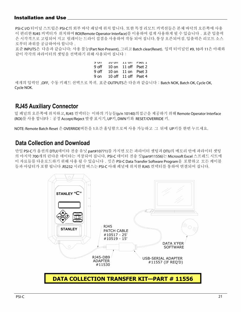
The ePro I/O terminal strip is located externally on the bottom of the ePro FSC. Certain remote connections are also accessible via the RJ45 socket located on the right side bottom panel and can be easily accessed using the ROI (Remote Operator Interface). Standard I/O is optically isolated and relay operated using dry contacts; normally open. I/O must be powered from a remote source.
Standard INPUTS are: Disable (Part Not-Present) and Batch Clear (Reset). Input terminals #9, 10 & 11 are used to select between the different Parameter Sets according to the following table:
9 off 10 off 11 on Pset 1 9 off 10 on 11 off Pset 2 9 off 10 on 11 on Pset 3 9 on 10 off 11 off Pset 4
All three inputs, OFF, returns to manual keypad selection. Standard OUTPUTS are: Batch NOK, Batch OK, Cycle OK, Cycle NOK.
RJ45 Auxiliary Connector Located on the right side of the bottom panel, the RJ45 connector uses a Remote Operator Interface (ROI) to provide access to thefollowing functions (p/n 10140): Cycle Accept/Reject indicator lights, UP button, DWN button and RESET/OVERRIDE button.
NOTE: Remote Batch Reset is available by holding the OVERRIDE button for one (1) second, then pressing the UP button once.
Data Collection and Download If the ePro FSC has the optional DTU (Data Transfer Unit, part #10771) all parameter sets and rundown data from the last 700 readings per Pset is stored in the memory of the DTU. The SigmaSIX Data Transfer Kit (part #11556) can be used to download thisdata to a Microsoft Excel spreadsheet. The kit includes the SigmaSIX Data Transfer Software Program and all cables and adapter required. An RS232 serial bus is ported through the RJ45 connector located on the bottom panel of the ePro FSC. The data is sent
DATA COLLECTION TRANSFER KIT—PART # 11556
STANLEY
STANLEY “c”
PSI-C I/O터미널스트립은 PSI-C의외부바닥패널에위치합니다. 또한특정리모트커넥션들은본체바닥의오른쪽에사용이편리한 RJ45 커넥터가 위치하며 ROI(Remote Operator Interface)를이용하여쉽게사용하게될수있습니다.표준입출력은시각적으로고립되어지고 릴레이는드라이접점을사용하여작동되어집니다.통상오픈되어짐.입출력은리모트소스로부터파워를공급하여야합니다.
표준 INPUTS은 다음과같습니다: 사용불능(Part Not-Present),그리고 Batch clear(Reset). 입력터미널인 #9, 10과 11은아래와같이각각의파라미터의셋팅을선택하기위해사용되어집니다:
세개의입력인 ,OFF, 수동키패드선택으로복귀. 표준 OUTPUTS은다음과같습니다:Batch NOK, Batch OK, Cycle OK,Cycle NOK.
밑페널의오른쪽에위치하고, RJ45컨넥터는 이하의기능들(p/n 10140)의접근을제공하기위해 Remote Operator Interface(ROI)를사용합니l다:공정 Accept/Reject 발광표시기, UP키, DWN키와 RESET/OVERRIDE키.
NOTE: Remote Batch Reset은 OVERRIDE버튼을 1초간홀딩함으로써사용가능하고 그 뒤에 UP키를한번누르세요.
만일 PSI-C가옵션의 DTU(데이타전송유닛 part#10771)를가지면모든파라미터셋팅과 DTU의메모리안에파라미터셋팅의마지막 700개의런다운데이타는저장되어집니다. PSI-C데이터전송킷(part#11556)는 Microsoft Excel스프레드시트에이자료들를다운로드하기위해사용될수있습니다.킷은 PSI-C Data Transfer Software Program을 포함하고 모든케이블들과아답터가포함됩니다 .RS232 시리얼버스는 PSI-C 아래페널에위치한 RJ45 컨넥터를통하여연결되어집니다.
21PSI-C

Installation and Use
23
NOMINAL CAL VALUE 230.0 MIN 75.4
TARGET TQ 80.0 HI LIMIT 92.0 MAX
LO LIMIT 68.0 90.8 THRESHOLD 24.0
AVG MIN PULSES 0 84.0
MAX PULSES 500 RANGE
DOWNSHIFT TQ 80.0 15.4 DOWNSHIFT PSI 70
STD. DEV. JOINT CONDITION PSI 0 3.024500481
JOINT CONDITION PULSES 0 6 SIGMA
START PSI 70 18.14700289 NUMBER OF BOLTS 3
FILTER FREQ 1150 Hz % 6 SIGMA 0.216156845
PRE TORQUE TARGET 0.0 PRETORQUE THRESHOLD 0 CPK
PRETORQUE PSI 50 0.886874695 CPR
NUMBER OF READINGS STORED 68 0.009006535
READING TIME/DATE RESULT 02-15-07 11:31:55 81.4 02-15-07 11:32:02 80.5 02-15-07 11:32:15 80.5 02-15-07 11:32:22 85.5
NetworkingThe ePro FSC is Network capable through a standard Network card.
1. EtherNET (TCP/IP): This optional card, part #10116, must be factory programmed for EtherNET. It is accessed via an RJ45 port located on the bottom panel of the enclosure. The EtherNET card communicates using TCP/IP and can be configured to utilize your communication software program.
2. PFCS (Chrysler): This communication protocol and hardware is available if the controller is being shipped to an approved Chrysler facility. PFCS is available in both Serial RS 232 and EtherNET formats. If the PFCS EtherNET network card has not been factory installed and the ePro is being converted to PFCS communication, follow the instructions below.
PFCS EtherNET network card: Remove jumpers from main control board (JP1 and JP2).
PFCS Serial network card: Remove all jumpers from main control board JP1 and install jumpers onto all positions on JP2.
Once the Data Collection Cable Assembly is correctly assembled, Open the SigmaSIX Data Collection Software Program. Select the COM Port. Go into the ADMIN MENU of the ePro FSC and scroll to DATA. Press ENTER. Press DOWN to download all data from the current Pset. Name and save the Excel Spreadsheet.
Press UP to CLEAR all DATA. The data is as follows:
데이터는보내집니다.데이터컬렉트어셈블리케이블이바르게연결되면 PSI-C 데이터컬렉트소프트프로그램을여세요. COM Port를선택하세요. PSI-C의 ADMIN MENU에들어가서 DATA를스크롤합니다.ENTER키를누르세요.현재의파라미터에서모든데이터를다운로드하기위해 DOWN키를누르세요. Excel Spreadshee의 이름을만들고저장하세요.
UP키를누르면모든 DATA는지워집니다.데이터는다음과같습니다:
PSI-C는는표준네트워크Network카드를통하여네트워크가가능합니다.
1. EtherNET(TCP/IP):이옵션의카드(part #10116)는 EtherNET를위해프로그램되는공장일것입니다.이것은콘트롤러의아래패널에위치한 RJ45 port를통하접근하게됩니다. EtherNET카드는 TCP/IP 사용을을연결하고 통신소프트웨어프로그램을이용하기위해구성될수있습니다.
2. PFCS(Chrydl ):이통신프로토콜과하드웨어는크라이슬러가승인한콘트롤러에대해서이용가능합니다 PFCS는시리얼인 RS 232와 EtherNET 포맷으로이용할수있습니다. PFCS EtherNET네트워크카드가인스톨되지않았고 PSI-C가PFCS통신으로에변환되고있으면, 아래의지시사항을따르세요.
PFCS EtherNET네트워크카드:컨트롤보드(JP1와 JP2)에서점퍼들를제거하세요.PFCS Serial네트워크카드:컨트롤보드 JP1에서모든점퍼들를제거하고 JP2에대한모든포지션의점퍼를인스톨하세요.
22 PSI-C