INSTALLATION AND OPERATION MANUAL · PDF fileFM40325D Filtration System INSTALLATION AND...
24
FM40325D Filtration System INSTALLATION AND OPERATION MANUAL By-Pass Filtration System To Suit CAT ® 793D Differential and Final Drive Lube System Issue 2: July 2015
Transcript of INSTALLATION AND OPERATION MANUAL · PDF fileFM40325D Filtration System INSTALLATION AND...

FM40325D Filtration System
INSTALLATION AND OPERATION MANUAL
By-Pass Filtration SystemTo Suit CAT® 793D Differential and Final DriveLube System
Issue 2: July 2015

Table of Contents
Page
1.0 Introduction 2
2.0 General Specifications 2
3.0 Main Components 5
3.1 Filter System 3
3.2 Supply Point 4
3.2 Return Point 4
4.0 Installation Details 5
4.1 System Installation Parts List 5
4.2 Hose Details 5
4.3 System Location 6
4.4 Oil Supply to Filter System 7
4.5 Oil Return to Compartment 11
4.6 Mounting of Filter System to Chassis 13
5.0 Commissioning 15
5.1 Establishing Correct Filter Housing Pressure 15
5.2 Commissioning Process 16
6.0 Assessing Element Condition 17
7.0 Servicing Procedure 18
8.0 Element Change Procedure 19
9.0 General Maintenance 20
10.0 Filter Technology Australia Contact Details 21
11.0 FM4 Installation Check Sheet 22
12.0 Notes 23
Page 1
INSTALLATION AND OPERATION MANUALFM40325 Series By-Pass Filtration Systems : CAT® 793D Diff & Final Drive

Page 2
1.0 Introduction
The FM40325D By-Pass Filtration System is designed to be permanently installed in position on the truck for the filtration of the differential and final drive lube system.
The system is based on the Filter Technology Australia ( FTA ) designed and patented FM2100 Industrial Oil and Fuel Element. This element removes particulate contamination down to 2 micron in size.
In order to provide effective filtration, the systems are sized to provide a filtration flow rate of a minimum 20% of the compartment volume per hour. It is critical to ensure the required turn-over of oil through the filters to remove and maintain contamination levels within the target range.
In the CAT 793D application, oil supply to the FTA filters is taken from the OEM supply to the existing Diff Lube Filtration System. Oil is returned from the FTA filters direct into the diff compartment via an inspection cover plate at the rear of the diff housing.
2.0 General System Specifications
Supply Pressure 210 bar ( 3,000 psi ) max.
Safe Working Pressure 10 bar ( 145 psi ) max.
Filter Housing Pressure - Maximum 5.0 bar ( 72 psi ) ΔP across relief valve +Return Line Pressure. See Section 5.1
Filter Housing Pressure – Normal Operation See Section 5.1
Return Line Pressure 1.5 bar ( 14.5 psi ) Max. See Section 5.1
Pressure Drop Across Filters ( ΔP )( New Elements ) 3.0 bar ( 45 psi )
3.0 bar +0.5 bar
( 45 psi +7.0 +7.0 psi
) -0.0 bar -0.0 psi
Element Change Pressure Filter Housing Operating Pressure+ 1.5 bar ( 22 psi ) See Section 5.1
Dirt holding Capacity 0.9 kg ( 2 lb ) per element
Table 1
INSTALLATION AND OPERATION MANUALFM40325 Series By-Pass Filtration Systems : CAT® 793D Diff & Final Drive

Page 3
3.0 Main Components
3.1 Filter System
Item 1: Filter SystemNo 2 Filter Housings
Serial Number Tag(out of view)
Live Sample Valve
Flow Control Valve
Pressure GaugeItem 6: Oil Return Hose
Item 2 : Oil Supply Hose
Relief Valve
Photo 1
INSTALLATION AND OPERATION MANUALFM40325 Series By-Pass Filtration Systems : CAT® 793D Diff & Final Drive

3.2 Supply Point
Item 2
Hose Assembly 246-5818
Items 3, 4, 5
3.3 Return Point
Photo 2 – Supply Point
Photo 3 – Return Point
Page 4
Item 6
Items 7,8
INSTALLATION AND OPERATION MANUALFM40325 Series By-Pass Filtration Systems : CAT® 793D Diff & Final Drive

Page 5
4.0 Installation Details
Record installation and commissioning details on check sheet at rear of this manual, see Section 11.0 FM4 System Installation Check Sheet.
4.1 System Installation Parts List
Item No. Description Part No Qty
1 Filtration System FM40325D 1
2 Hose Assembly ( Supply ) FMH9060 1
3 Elbow FMH2209 1
4 Face Seal O Ring FMM4001 1
5 Tee FM0445 1
6 Elbow FMH2313 1
7 Hose Assembly ( Return ) FMH9061 1
8 Return Cover FM0446 1
9 Return Cover Seal O Ring FMM4030 1
Table 2
4.2 Hose DetailsAs a minimum, all hosing shall be of industrial quality hydraulic hose complying with AS 3791 – Hydraulic Hose and also site and statutory requirements.
Correct sizing of hosing is specific to each application however, typically, shall be of suitable diameter to provide unrestricted flow of oil with regard to the oil viscosity and length of hose used. Typically, it is recommended to use one hose size larger on the return line than the supply line to ensure no possibility of excessive return line back pressure exists.
Ensure hosing is thoroughly cleaned after manufacture and prior to installation. Hosing shall be secured at regular intervals in such a manner as to ensure no risk of failure through mechanical, heat, abrasion or other damage, all in accordance with site and statutory requirements.
Any changes or modifications made to OEM hose mounting arrangements must include alternative means of securing such hoses to a standard of no less than the original arrangement.
INSTALLATION AND OPERATION MANUALFM40325 Series By-Pass Filtration Systems : CAT® 793D Diff & Final Drive

Page 6
4.3 System LocationThe system is mounted to the inside of the left hand chassis beam, see Figure 1.
Figure 1
INSTALLATION AND OPERATION MANUALFM40325 Series By-Pass Filtration Systems : CAT® 793D Diff & Final Drive

Page 7
4.4 Oil Supply to Filter System
1. Locate hose assembly 246-5818, see Photo 4.
2. Remove mounting clamp assembly, see Photo 4.
3. Disconnect hose 246-5818 from elbow assembly 148-8373, see Photo 4.
4. Remove elbow assembly 148-8373 from block 9N-4685, see Photo 4.
5. Install elbow FMH2209 into block 9N-4685, see Photo 5.
6. Install tee FM0445 to elbow FMH2209, see Photo 5.
7. Install elbow FMH2313 to tee FM0445, see Photo 5.
8. Connect hose 246-5818 to tee FM0445, see Photo 4.
9. Install shorter bolt to secure steel lines where mounting clamp assembly (Item 2 above) was previously installed, see Photo 6.
10. Install P clamp to brake cooling hose 125-5085 and connect to original mounting clamp which supports hose 246-5818, see Photo 7. Position clamps to ensure that neither hose rubs at any location.
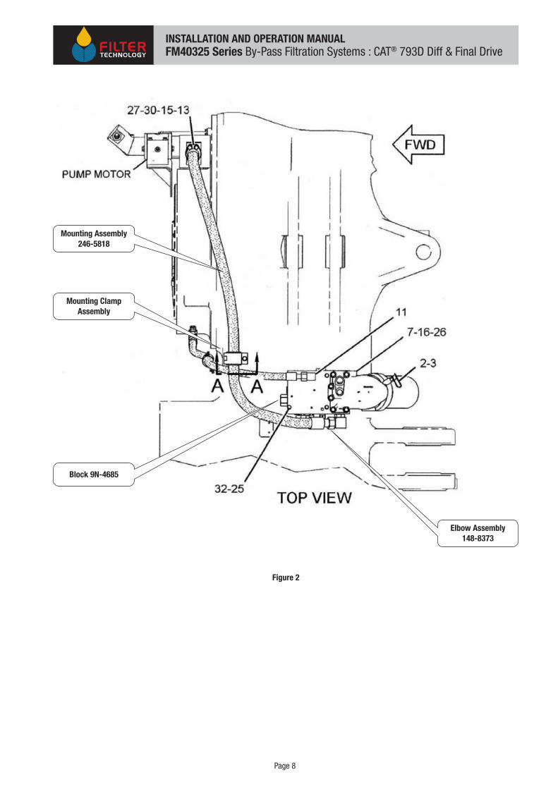
11. Install supply hose FMH9060 to elbow FMH2313, see Photo 4. Run opposite end of hose forward to approximate location of filter system mounting position, see Figure 1.
INSTALLATION AND OPERATION MANUALFM40325 Series By-Pass Filtration Systems : CAT® 793D Diff & Final Drive
Page 8
Elbow Assembly148-8373
Mounting Clamp Assembly
Mounting Assembly246-5818
Block 9N-4685
Figure 2
INSTALLATION AND OPERATION MANUALFM40325 Series By-Pass Filtration Systems : CAT® 793D Diff & Final Drive

Page 9
Photo 4
Photo 5
Supply HoseFMH9060
ElbowFMH2313
Hose Assembly 246-5818
TeeFM0445
ElbowFMH2313
TeeFM0445
ElbowFMH2209
INSTALLATION AND OPERATION MANUALFM40325 Series By-Pass Filtration Systems : CAT® 793D Diff & Final Drive

Page 10
Photo 6
Shorter bolt to suit
Photo 7
Original Mounting Clamp
Brake Cooling Hose125-5085
P Clamp
Hose246-5818
INSTALLATION AND OPERATION MANUALFM40325 Series By-Pass Filtration Systems : CAT® 793D Diff & Final Drive

Page 11
4.5 Oil Return To Compartment
1. Locate left side inspection cover 8X-2933 and remove, see Figure 3.
2. Install Return Cover FM0046 and Seal O Ring FMM4030 as shown, see Photo 8.
3. Install Return Hose FMH9061 to Return Cover FM0046, see Photo 9. Run opposite end of hose forward to approximate location of filter system mounting position, see Figure 1.
CoverLeft Hand Side
Figure 3
INSTALLATION AND OPERATION MANUALFM40325 Series By-Pass Filtration Systems : CAT® 793D Diff & Final Drive

Page 12
Photo 8
Return CoverFM0448
Seal O RingFMM4031
Photo 9
Return HoseFMH9061
INSTALLATION AND OPERATION MANUALFM40325 Series By-Pass Filtration Systems : CAT® 793D Diff & Final Drive

Page 13
4.6 Mounting of Filtration System
The filtration system has been designed to mount to the diff oil cooler mounting position. The mounting holes on the filtration unit have been spaced to directly mount to the diff oil cooler mount bosses on the chassis cross member.
If a diff oil cooler has been fitted to the truck there will be an extra mount frame supplied to add to the diff oil cooler bracket which then allows the filtration unit to be mounted.
This mounting system needs no modifications to the chassis. It only requires four extra holes to be drilled to the front of the diff oil cooler mounting brackets.
INSTALLATION AND OPERATION MANUALFM40325 Series By-Pass Filtration Systems : CAT® 793D Diff & Final Drive

Page 14
Photo 10
INSTALLATION AND OPERATION MANUALFM40325 Series By-Pass Filtration Systems : CAT® 793D Diff & Final Drive

5.0 Commissioning
Optimum filtration system performance relies on the correct setting of the housing
pressure at commissioning.
Because most installations are unique in some manner, pressures must be set at
installation to suit the particular system.
5.1 Establishing Correct Filter Housing Operating Pressure
To establish the optimum Filter Housing Pressure, perform the following calculation where:-
RLP = Return Line Pressure ( Return Line Back Pressure + Return Line Check Valve Cracking Pressure - See Table 1 )
FHP = Filter Housing Pressure
ΔP = Required Pressure Drop Across Filters
FHP = RLP + ΔP
Example 1
Pressure bar psi
RLP 1.2 17.4
ΔP 3.0 43.5
FHP 4.2 60.9
Element Change Pressure = 4.2 bar + 1.5 bar = 5.7 bar
Element Change Pressure = 60.9 psi + 22 psi = 82.9 psi
Example 2
Pressure bar psi
RLP 0.5 7.25
ΔP 3.0 43.5
FHP 3.5 50.75
Element Change Pressure = 3.5 bar + 1.5 bar = 5.0 bar
Element Change Pressure = 50.75 psi + 22 psi = 72.75 psi
Record installation and commissioning details on check sheet at rear of this manual.
Page 15
INSTALLATION AND OPERATION MANUALFM40325 Series By-Pass Filtration Systems : CAT® 793D Diff & Final Drive

Page 16
5.2 Commissioning Process
Commission the system as follows :-
1. Ensure Isolation Valve is closed.
2. Ensure Flow Control Valve is screwed in clockwise 100% to closed position.
3. Bring the oil system to operating temperature and pressures.
4. Open the Isolation Valve.
5. While observing the pressure gauge, slowly open the flow control valve to establish oil flow into the filter housing(s), adjust to approximately 3.0 bar.
6. Allow oil to flow through system for a short while, say 5 – 10 minutes to remove any air trapped in the filter housing(s). Pressure may fluctuate during this period.
7. Check and record Return Line pressure.
8. Calculate filter housing pressure – see Section 5.1.
9. Re-adjust filter housing pressure, previously set in step 5 above, and set to value determine in step 8 above.
10. Check and confirm Return Line Pressure has not increased above value determined in step 7 above. If Return Line Pressure has increased with oil flowing back to tank, this indicates the Return Line may have some restriction to flow. Investigate for restrictive fittings or other cause. If necessary, increase hose diameter to accommodate oil flow.
11. Inspect installation for any leaks and rectify as required if any.
12. Allow system to operate for 2 – 3 hours and check/reset housing pressure to values determined above.
NOTE: Setting and Adjustment of Housing Pressure
The commissioning procedure should only be conducted with clean elements installed.
Once set at commissioning, the housing pressure must not be adjusted during normal operation even though it will be noticed that housing pressure will increase as the elements “load up” with contamination.
See Section 6 – Assessing Element Condition for further information.
INSTALLATION AND OPERATION MANUALFM40325 Series By-Pass Filtration Systems : CAT® 793D Diff & Final Drive

Page 17
6.0 Assessing Element Condition
Typical element change interval is 500 hours, designed to align with typical OEM service intervals.
Under normal conditions, the unit will run at the specified pressure set at commissioning on clean elements.
Over time the level of contamination loading increases on the elements. This causes a restriction to the flow of oil through the elements. With increasing contamination the level of restriction increases also. Increasing levels of restriction result in increasing pressure in the filter element housing which is seen on the pressure gauge.
When housing pressure reaches the nominated value the elements are considered to be fully loaded with contamination and the elements should be changed.
NOTE: When housing pressure approaches maximum Filter Housing Pressure (see Table1) relief valves starts to “crack” open. At maximum Filter Housing Pressure the relief valve is fully open directing most of the oil flow back to the compartment unfiltered. At this stage very little oil is being filtered and the system must be serviced as soon as possible.
See Section 7 – Servicing Procedure for further information.
INSTALLATION AND OPERATION MANUALFM40325 Series By-Pass Filtration Systems : CAT® 793D Diff & Final Drive

Page 18
7.0 Servicing Procedure
Perform the element change procedure as follows:-
1. Isolation of System
a. Implement machine isolation procedures as required.
2. Removal of Filter Element Assembly
a. Using a clean rag or paper towel, clean away any dirt etc from around the lid of the filter housing.
b. Rotate the Tee handle at the top of the filter housing in an anti-clockwise direction to unscrew it and disengage the thread in the base of the housing, see Photo 11.
c. Lift the filter element assembly out of the housing and place in a suitable drip tray.
d. Place a suitable cover over the top of the housing to prevent contamination entry while the element assembly is removed.
3. Change Filter Elements
a. Replace filter elements see “Element Change Procedure”.
4. Install Filter Element Assembly
a. Insert filter element assembly into element housing.
b. Locate threaded end of return tube into the “lead” into the base of housing, see Photo 12.
c. Rotate Tee handle in a clockwise direction to engage thread and screw in.
d. Ensure lid seals engage housing correctly to avoid pinching and possible damage.
e. Continue to screw Tee handle down until lid seats firmly against housing.
f. Rotate Tee handle a further 180° to apply final tension.
g. Wipe down any oil residue.
5. Return System to Service
a. Start system and bring to operating temperature.
b. Observe housing pressure. After a short while, as air bleeds from the housing(s), it should settle at the specified Filter Housing Pressure.
c. Check system for any leaks, particularly around the lid seal area. Rectify as required.
d. System now ready for return to service.
Photo 11 Photo 12
“Lead” into thread
Element assembly screwed into housing base
INSTALLATION AND OPERATION MANUALFM40325 Series By-Pass Filtration Systems : CAT® 793D Diff & Final Drive
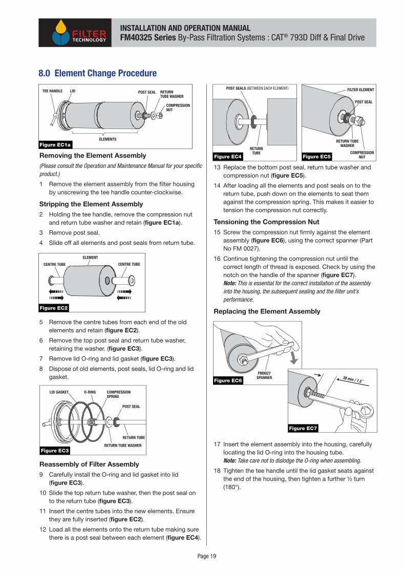
Removing the Element Assembly(Please consult the Operation and Maintenance Manual for your specific product.) 1 Remove the element assembly from the filter housing
by unscrewing the tee handle counter-clockwise.
Stripping the Element Assembly2 Holding the tee handle, remove the compression nut
and return tube washer and retain (figure EC1a).
3 Remove post seal.
4 Slide off all elements and post seals from return tube.
5 Remove the centre tubes from each end of the old elements and retain (figure EC2).
6 Remove the top post seal and return tube washer, retaining the washer. (figure EC3).
7 Remove lid O-ring and lid gasket (figure EC3).
8 Dispose of old elements, post seals, lid O-ring and lid gasket.
Reassembly of Filter Assembly9 Carefully install the O-ring and lid gasket into lid
(figure EC3).
10 Slide the top return tube washer, then the post seal on to the return tube (figure EC3).
11 Insert the centre tubes into the new elements. Ensure they are fully inserted (figure EC2).
12 Load all the elements onto the return tube making sure there is a post seal between each element (figure EC4).
13 Replace the bottom post seal, return tube washer and compression nut (figure EC5).
14 After loading all the elements and post seals on to the return tube, push down on the elements to seat them against the compression spring. This makes it easier to tension the compression nut correctly.
Tensioning the Compression Nut15 Screw the compression nut firmly against the element
assembly (figure EC6), using the correct spanner (Part No FM 0027).
16 Continue tightening the compression nut until the correct length of thread is exposed. Check by using the notch on the handle of the spanner (figure EC7). Note: This is essential for the correct installation of the assembly into the housing, the subsequent sealing and the filter unit’s performance.
Replacing the Element Assembly
17 Insert the element assembly into the housing, carefully locating the lid O-ring into the housing tube. Note: Take care not to dislodge the O-ring when assembling.
18 Tighten the tee handle until the lid gasket seats against the end of the housing, then tighten a further ½ turn (180°).
COMPRESSIONNUT
RETURNTUBE WASHER
TEE HANDLE
ELEMENTS
LID
Figure EC1a
POST SEAL
Figure EC2
CENTRE TUBE CENTRE TUBE
ELEMENT
COMPRESSIONSPRING
POST SEAL
RETURN TUBE
LID GASKET O-RING
RETURN TUBE WASHERFigure EC3
POST SEALS (BETWEEN EACH ELEMENT)
RETURNTUBE
Figure EC4
Figure EC6
FM0027SPANNER 38 mm / 1.5 ˝
Figure EC7
COMPRESSIONNUT
POST SEAL
FILTER ELEMENT
RETURN TUBEWASHER
Figure EC5
Page 19
8.0 Element Change Procedure
INSTALLATION AND OPERATION MANUALFM40325 Series By-Pass Filtration Systems : CAT® 793D Diff & Final Drive

Page 20
9.0 General Maintenance
General maintenance tasks as follows:-
1. Structural
a. Check all installation bolts are firm and correctly tensioned.
b. Check for any cracks in mounting system or supporting structures.
2. Filtration System
a. Pressure gauge functional and in good condition.
b. Check all hydraulic hoses for:-
i. Leaks
ii. Signs of rubbing
iii. Securely clamped
c. Check housing mounting clamps all correctly tensioned
d. Check dust caps fitted to:-
i. Live Sample Valve
ii. Return Line Pressure Test Point
INSTALLATION AND OPERATION MANUALFM40325 Series By-Pass Filtration Systems : CAT® 793D Diff & Final Drive
10.0 Equipment Placement Contact Details
Page 21
INSTALLATION AND OPERATION MANUALFM40325 Series By-Pass Filtration Systems : CAT® 793D Diff & Final Drive
Head Office/Manufacturing FacilityFilter Technology Australia
Office/Warehouse/Manufacturing Facility:44 Bonville Avenue, Thornton NSW 2322
Sales and Support: Chris Wells: [email protected]
Postal:PO Box 101 Beresfield NSW 2322
Tel: +61 2 4966 1833Fax: +61 2 4966 1933 Toll Free Australia: 1800 626 899
Email: [email protected]
www.filtertechnology.com.au
Distributors:
Western Australia
Equipment Placement
Office:11 Fairbrother Street, Belmont, WA 6104
Postal Address:PO Box 834, Cloverdale WA 6985
Tel: +61 8 9479 4988Fax: +61 8 9479 4588
www.equipmentplacement.com.au
For details of your local distributor please go to:
www.filtertechnology.com.au/pages/contact.htm
Page 23
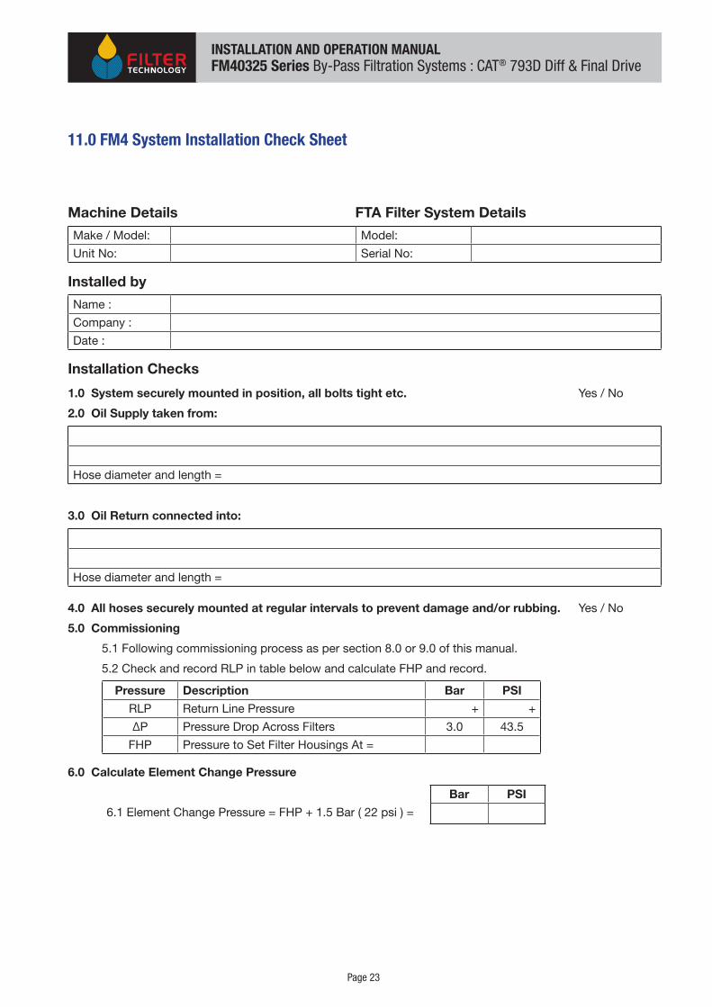
11.0 FM4 System Installation Check Sheet
Machine Details FTA Filter System Details
Make / Model: Model:
Unit No: Serial No:
Installed by
Name :
Company :
Date :
Installation Checks
1.0 System securely mounted in position, all bolts tight etc. Yes / No
2.0 Oil Supply taken from:
Hose diameter and length =
3.0 Oil Return connected into:
Hose diameter and length =
4.0 All hoses securely mounted at regular intervals to prevent damage and/or rubbing. Yes / No
5.0 Commissioning
5.1 Following commissioning process as per section 8.0 or 9.0 of this manual.
5.2 Check and record RLP in table below and calculate FHP and record.
Pressure Description Bar PSI
RLP Return Line Pressure + +
ΔP Pressure Drop Across Filters 3.0 43.5
FHP Pressure to Set Filter Housings At =
6.0 Calculate Element Change Pressure
Bar PSI
6.1 Element Change Pressure = FHP + 1.5 Bar ( 22 psi ) =
INSTALLATION AND OPERATION MANUALFM40325 Series By-Pass Filtration Systems : CAT® 793D Diff & Final Drive

12.0 Notes
Page 22
INSTALLATION AND OPERATION MANUALFM40325 Series By-Pass Filtration Systems : CAT® 793D Diff & Final Drive