Sand Filtration System Owners Manual Installation ... · Sand Filtration System Owners Manual...
9
Sand Filtration System Owners Manual Installation, Operation, and Parts SHOW FILTRATION SYSTEM
Transcript of Sand Filtration System Owners Manual Installation ... · Sand Filtration System Owners Manual...

Sand Filtration System Owners Manual
Installation, Operation, and Parts
SHOW FILTRATION SYSTEM
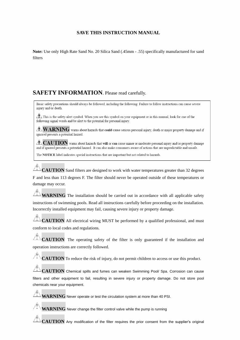
SAVE THIS INSTRUCTION MANUAL
Note: Use only High Rate Sand No. 20 Silica Sand (.45mm - .55) specifically manufactured for sand
filters
SAFETY INFORMATION. Please read carefully.
CAUTION Sand filters are designed to work with water temperatures greater than 32 degrees
F and less than 113 degrees F. The filter should never be operated outside of these temperatures or
damage may occur.
WARNING The installation should be carried out in accordance with all applicable safety
instructions of swimming pools. Read all instructions carefully before proceeding on the installation.
Incorrectly installed equipment may fail, causing severe injury or property damage.
CAUTION All electrical wiring MUST be performed by a qualified professional, and must
conform to local codes and regulations.
CAUTION The operating safety of the filter is only guaranteed if the installation and
operation instructions are correctly followed.
CAUTION To reduce the risk of injury, do not permit children to access or use this product.
CAUTION Chemical spills and fumes can weaken Swimming Pool/ Spa. Corrosion can cause
filters and other equipment to fail, resulting in severe injury or property damage. Do not store pool
chemicals near your equipment.
WARNING Never operate or test the circulation system at more than 40 PSI.
WARNING Never change the filter control valve while the pump is running
CAUTION Any modification of the filter requires the prior consent from the supplier’s original

replacement parts and accessories authorized by the manufacturer ensure a high level of safety. The
supplier assumes no liability for the damage and injuries caused by unauthorized replacement parts and
accessories.
How It Works
Incoming water from the piping system is automatically directed by the Multiport Valve to the
top of the filter bed. As the water is pumped through the filter sand, dirt and debris are
trapped by the filter bed, and filtered out. The filtered water is returned from the bottom of
the filter tank, through the Multiport Valve and back through the piping system
Preparation Before Installation
1. The filter system should be installed, not more than 6 feet above pool water level, on a concrete
slab, very firm ground, or equivalent, as recommended by your pool dealer. Position the filter so
that the piping connections, control valve and winter drain are convenient and accessible for
operation, service, and winterizing.
2. Ensure that the compliance label is facing the front to allow easy identification in the case of service
difficulties.
3. The following tools will be needed for the installation of your filtration system; screwdriver, wrenches,
Pipe sealant will also be needed for plastic adapters.
How to install the filter tank
1. Assemble the pump to mounting base.
2. Install laterals and center pipe in filter tank
3. Place filter tank onto mounting base
4. Cover opening in internal pipe to prevent sand from entering. Be certain that pipe is securely in
place
5. Fill filter tank approximately ½ way with water to cushion the filter sand as it is poured into the
filter tank
NOTE: Prior to filling filter with sand, check to insure that laterals are in the down position
6. Carefully pour in the correct amount of sand. (make certain that the center pipe remains centered).
The top of the sand should come within 6” of the top of the filter tank.
7. Assemble filter control valve to top of filter tank.
Loosely pre-assemble both halves of the clamp with one screw and nut, turning nut 2-3 turns. Do not
tighten.
8. Insert filter control valve (with flange clamp and O-ring in place) onto the tank neck. Make
certain that the center pipe slips into the hole in the bottom of the valve. Install clamp around tank
and valve flange and assemble second screw and nut Tighten just enough so that the valve can be
rotated on the tank for final positioning.
9. Wrap Teflon tape on the pressure gauge threads and insert into the tapped hole on the valve body.
Do not over tighten.
10. Connect pump to control valve opening marked PUMP. After connections are made, tighten
valve flange clamp with screwdriver.
11. Make return to pool pipe connection to control valve opening marked RETURN and complete

other necessary plumbing connections, suction lines to pump, waste, etc.
12. Make electrical connections to pump
Initial Start-Up of Filtration System
1. Inspect all the connections have been made correct and are secure.
2. Depress top mount valve handle and rotate to BACKWASH position.
3. Prime and start pump according to pump instructions allowing the filter tank to fill with water.
NOTE: ALL SUCTION AND DISCHARGE VALVES MUST BE OPENING WHEN STARTING
THE SYSTEM. FAILURE TO DO SO COULD CAUSE SEVERE PERSONAL INJURY.
Once the water flow is steady out the waste line, run the pump for at least 2 minutes. The initial
back-washing of the filter is recommended to remove any impurities of fine sand particles in the
sand media.
4. Turn pump off and set valve to RINSE position. Start pump and operate until water in sight
glass is clear----about 1/2 to 1 minute. Turn pump off, set valve to FILTER position and restart
pump. Your filter is now operating in the normal filter mode, filtering particles from the pool
water.
5. Adjust pool suction and return valves to achieve desired flow. Check system and filter for leaks
and tighten connections if required.
NOTES:
1. Note the initial pressure gauge reading when the filter is clean. (It will vary from pool to pool
depending upon the pump and general piping system). As the filter removes dirt and impurities
from the pool water, the accumulation in the filter will cause the pressure to rise and flow to
diminish. When the pressure gauge reading is 8-10 PSI(0.55-0.69 BAR) higher than the initial
“clean” pressure you noted, it is the time to backwash (clean) the filter.
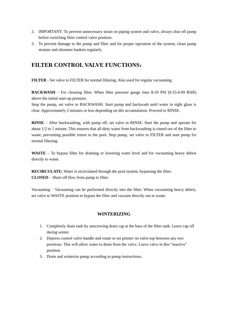
2. IMPORTANT: To prevent unnecessary strain on piping system and valve, always shut off pump
before switching filter control valve position.
3. To prevent damage to the pump and filter and for proper operation of the system, clean pump
strainer and skimmer baskets regularly.
FILTER CONTROL VALVE FUNCTIONS:
FILTER - Set valve to FILTER for normal filtering. Also used for regular vacuuming.
BACKWASH – For cleaning filter. When filter pressure gauge rises 8-10 PSI (0.55-0.69 BAR)
above the initial start-up pressure.
Stop the pump, set valve to BACKWASH. Start pump and backwash until water in sight glass is
clear. Approximately 2 minutes or less depending on dirt accumulation. Proceed to RINSE.
RINSE – After backwashing, with pump off, set valve to RINSE. Start the pump and operate for
about 1/2 to 1 minute. This ensures that all dirty water from backwashing is rinsed out of the filter to
waste, preventing possible return to the pool. Stop pump, set valve to FILTER and start pump for
normal filtering.
WASTE – To bypass filter for draining or lowering water level and for vacuuming heavy debris
directly to waste.
RECIRCULATE: Water is recirculated through the pool system, bypassing the filter.
CLOSED – Shuts off flow from pump to filter.
Vacuuming – Vacuuming can be performed directly into the filter. When vacuuming heavy debris,
set valve to WASTE position to bypass the filter and vacuum directly out to waste.
WINTERIZING
1. Completely drain tank by unscrewing drain cap at the base of the filter tank. Leave cap off
during winter.
2. Depress control valve handle and rotate to set pointer on valve top between any two
positions. This will allow water to drain from the valve. Leave valve in this “inactive”
position.
3. Drain and winterize pump according to pump instructions.
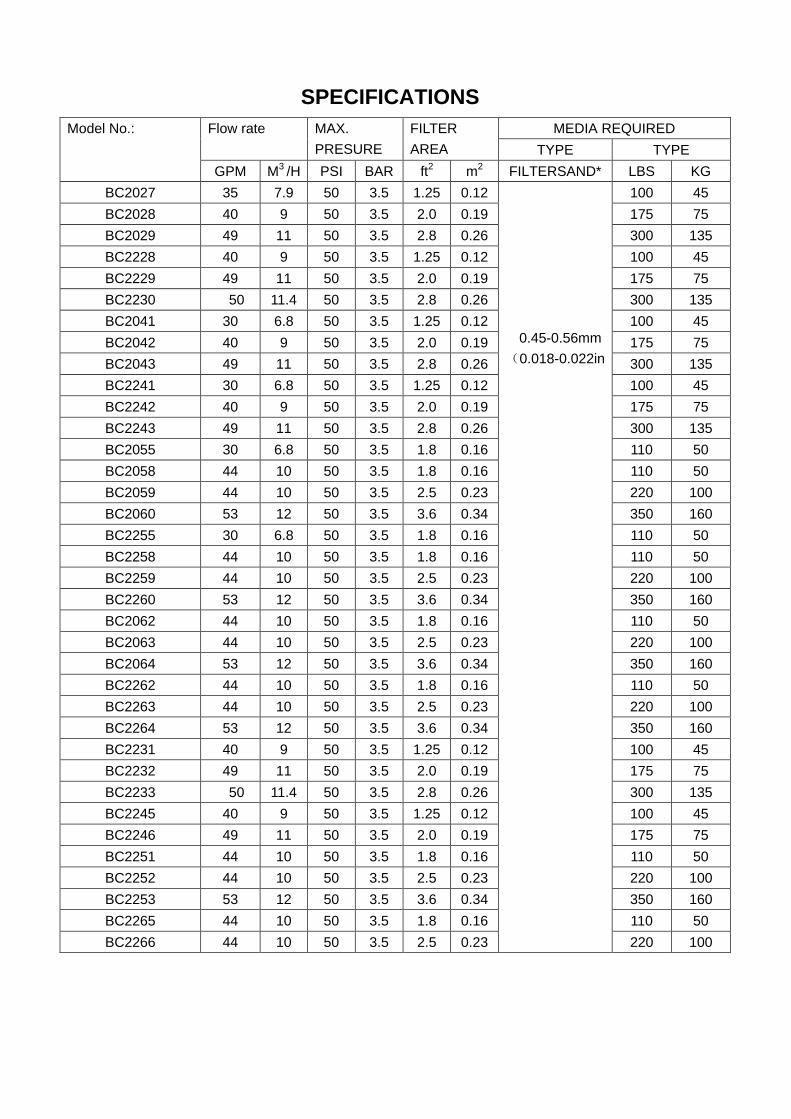
SPECIFICATIONS
Model No.: Flow rate MAX.
PRESURE
FILTER
AREA
MEDIA REQUIRED
TYPE TYPE
GPM M3 /H PSI BAR ft
2 m
2 FILTERSAND* LBS KG
BC2027 35 7.9 50 3.5 1.25 0.12
0.45-0.56mm
(0.018-0.022in
100 45
BC2028 40 9 50 3.5 2.0 0.19 175 75
BC2029 49 11 50 3.5 2.8 0.26 300 135
BC2228 40 9 50 3.5 1.25 0.12 100 45
BC2229 49 11 50 3.5 2.0 0.19 175 75
BC2230 50 11.4 50 3.5 2.8 0.26 300 135
BC2041 30 6.8 50 3.5 1.25 0.12 100 45
BC2042 40 9 50 3.5 2.0 0.19 175 75
BC2043 49 11 50 3.5 2.8 0.26 300 135
BC2241 30 6.8 50 3.5 1.25 0.12 100 45
BC2242 40 9 50 3.5 2.0 0.19 175 75
BC2243 49 11 50 3.5 2.8 0.26 300 135
BC2055 30 6.8 50 3.5 1.8 0.16 110 50
BC2058 44 10 50 3.5 1.8 0.16 110 50
BC2059 44 10 50 3.5 2.5 0.23 220 100
BC2060 53 12 50 3.5 3.6 0.34 350 160
BC2255 30 6.8 50 3.5 1.8 0.16 110 50
BC2258 44 10 50 3.5 1.8 0.16 110 50
BC2259 44 10 50 3.5 2.5 0.23 220 100
BC2260 53 12 50 3.5 3.6 0.34 350 160
BC2062 44 10 50 3.5 1.8 0.16 110 50
BC2063 44 10 50 3.5 2.5 0.23 220 100
BC2064 53 12 50 3.5 3.6 0.34 350 160
BC2262 44 10 50 3.5 1.8 0.16 110 50
BC2263 44 10 50 3.5 2.5 0.23 220 100
BC2264 53 12 50 3.5 3.6 0.34 350 160
BC2231 40 9 50 3.5 1.25 0.12 100 45
BC2232 49 11 50 3.5 2.0 0.19 175 75
BC2233 50 11.4 50 3.5 2.8 0.26 300 135
BC2245 40 9 50 3.5 1.25 0.12 100 45
BC2246 49 11 50 3.5 2.0 0.19 175 75
BC2251 44 10 50 3.5 1.8 0.16 110 50
BC2252 44 10 50 3.5 2.5 0.23 220 100
BC2253 53 12 50 3.5 3.6 0.34 350 160
BC2265 44 10 50 3.5 1.8 0.16 110 50
BC2266 44 10 50 3.5 2.5 0.23 220 100
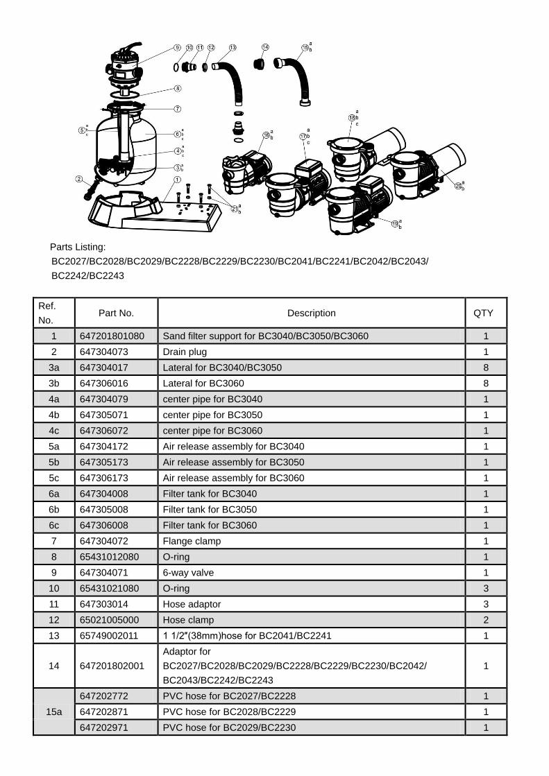
Parts Listing:
BC2027/BC2028/BC2029/BC2228/BC2229/BC2230/BC2041/BC2241/BC2042/BC2043/
BC2242/BC2243
Ref.
No. Part No. Description QTY
1 647201801080 Sand filter support for BC3040/BC3050/BC3060 1
2 647304073 Drain plug 1
3a 647304017 Lateral for BC3040/BC3050 8
3b 647306016 Lateral for BC3060 8
4a 647304079 center pipe for BC3040 1
4b 647305071 center pipe for BC3050 1
4c 647306072 center pipe for BC3060 1
5a 647304172 Air release assembly for BC3040 1
5b 647305173 Air release assembly for BC3050 1
5c 647306173 Air release assembly for BC3060 1
6a 647304008 Filter tank for BC3040 1
6b 647305008 Filter tank for BC3050 1
6c 647306008 Filter tank for BC3060 1
7 647304072 Flange clamp 1
8 65431012080 O-ring 1
9 647304071 6-way valve 1
10 65431021080 O-ring 3
11 647303014 Hose adaptor 3
12 65021005000 Hose clamp 2
13 65749002011 1 1/2″(38mm)hose for BC2041/BC2241 1
14 647201802001
Adaptor for
BC2027/BC2028/BC2029/BC2228/BC2229/BC2230/BC2042/
BC2043/BC2242/BC2243
1
15a
647202772 PVC hose for BC2027/BC2228 1
647202871 PVC hose for BC2028/BC2229 1
647202971 PVC hose for BC2029/BC2230 1
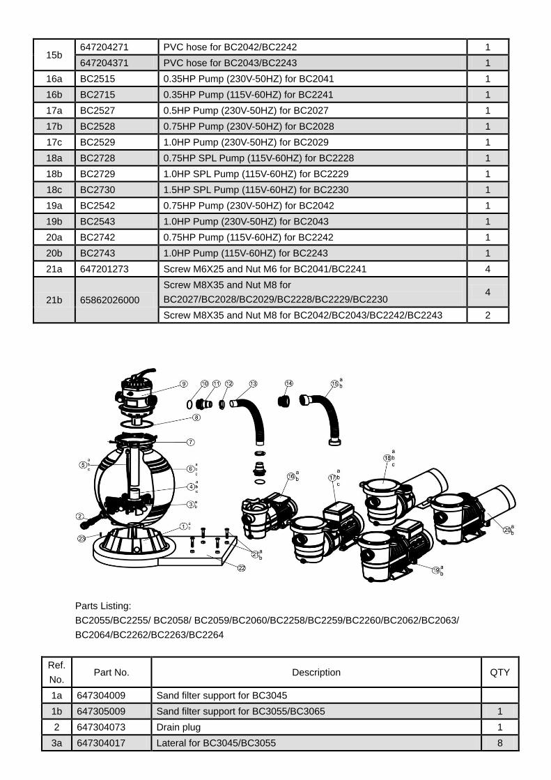
15b 647204271 PVC hose for BC2042/BC2242 1
647204371 PVC hose for BC2043/BC2243 1
16a BC2515 0.35HP Pump (230V-50HZ) for BC2041 1
16b BC2715 0.35HP Pump (115V-60HZ) for BC2241 1
17a BC2527 0.5HP Pump (230V-50HZ) for BC2027 1
17b BC2528 0.75HP Pump (230V-50HZ) for BC2028 1
17c BC2529 1.0HP Pump (230V-50HZ) for BC2029 1
18a BC2728 0.75HP SPL Pump (115V-60HZ) for BC2228 1
18b BC2729 1.0HP SPL Pump (115V-60HZ) for BC2229 1
18c BC2730 1.5HP SPL Pump (115V-60HZ) for BC2230 1
19a BC2542 0.75HP Pump (230V-50HZ) for BC2042 1
19b BC2543 1.0HP Pump (230V-50HZ) for BC2043 1
20a BC2742 0.75HP Pump (115V-60HZ) for BC2242 1
20b BC2743 1.0HP Pump (115V-60HZ) for BC2243 1
21a 647201273 Screw M6X25 and Nut M6 for BC2041/BC2241 4
21b 65862026000
Screw M8X35 and Nut M8 for
BC2027/BC2028/BC2029/BC2228/BC2229/BC2230 4
Screw M8X35 and Nut M8 for BC2042/BC2043/BC2242/BC2243 2
Parts Listing:
BC2055/BC2255/ BC2058/ BC2059/BC2060/BC2258/BC2259/BC2260/BC2062/BC2063/
BC2064/BC2262/BC2263/BC2264
Ref.
No. Part No. Description QTY
1a 647304009 Sand filter support for BC3045
1b 647305009 Sand filter support for BC3055/BC3065 1
2 647304073 Drain plug 1
3a 647304017 Lateral for BC3045/BC3055 8

3b 647306016 Lateral for BC3065 8
4a 647304571 Center pipe for BC3045 1
4b 647305571 Center pipe for BC3055 1
4c 647306571 Center pipe for BC3065 1
5a 647304172 Air release assembly for BC3045 1
5b 647305173 Air release assembly for BC3055 1
5c 647306173 Air release assembly for BC3065 1
6a 647304501 Filter tank for BC3045 1
6b 647305501 Filter tank for BC3055 1
6c 647306501 Filter tank for BC3065 1
7 647304072 Flange clamp 1
8 65431012080 O-ring 1
9 647304071 6-Way valve 1
10 65431021080 O-ring 3
11 647303014 Hose adaptor 3
12 65021005000 Hose clamp 2
13 65749002011 1 1/2″(38mm)hose for BC2055/BC2255 1
14 647201802001 Adaptor for BC2058/BC2059/BC2060/BC2258/BC2259/BC2260/
BC2062/BC2063/BC2064/BC2262/BC2263/BC2264 1
15a
647205871 PVC hose for BC2027/BC2228 1
647205971 PVC hose for BC2028/BC2229 1
647202971 PVC hose for BC2029/BC2230 1
15b 647206371 PVC hose for BC2042/BC2242 1
647204371 PVC hose for BC2043/BC2243 1
16a BC2515 0.35HP Pump (230V-50HZ) for BC2041 1
16b BC2715 0.35HP Pump (115V-60HZ) for BC2241 1
17a BC2527 0.5HP Pump (230V-50HZ) for BC2027 1
17b BC2528 0.75HP Pump (230V-50HZ) for BC2028 1
17c BC2529 1.0HP Pump (230V-50HZ) for BC2029 1
18a BC2728 0.75HP SPL Pump (115V-60HZ) for BC2228 1
18b BC2729 1.0HP SPL Pump (115V-60HZ) for BC2229 1
18c BC2730 1.5HP SPL Pump (115V-60HZ) for BC2230 1
19a BC2542 0.75HP Pump (230V-50HZ) for BC2042 1
19b BC2543 1.0HP Pump (230V-50HZ) for BC2043 1
20a BC2742 0.75HP Pump (115V-60HZ) for BC2242 1
20b BC2743 1.0HP Pump (115V-60HZ) for BC2243 1
21a 647201273 Screw M6X25 and Nut M6 for BC2041/BC2241 4
21b 65862026000
Screw M8X35 and Nut M8 for
BC2027/BC2028/BC2029/BC2228/BC2229/BC2230 4
Screw M8X35 and Nut M8 for BC2042/BC2043/BC2242/BC2243 2
22 647204801080 Sand filter support for BC3045/BC3055/BC3065 1
23 6512012000 Screw ST4.8X20 4