Installation and Operation Manual -...
24
H0303600A Installation and Operation Manual WARNING FOR YOUR SAFETY - This product must be installed and serviced by a professional pool/ spa service technician. The procedures in this manual must be followed exactly. Failure to follow warning notices and instructions may result in property damage, serious injury, or death. Improper installation or operation will void the warranty. Installation Data Levolor ® by Jandy ® Electronic Water Leveler Models K-1100, LX2, K-2300, and LEV110CK/2G Sensor Filling Power DO NOT OPEN NO USER SERVICEABLE PARTS INSIDE SENSOR PWR FILL II Electronic Water Levelor The next generation in automated controls. Patented High Voltage Compartment No user service parts inside Model No. K-2300 Sensor I Sensor II Filling 1 Filling II Power K-1100 LX2 K-2300 Sensor Filling Power Model No. LEV110CK/2G LEV110CK/2G
Transcript of Installation and Operation Manual -...

H03
0360
0A
Installation and Operation Manual
WARNINGFOR YOUR SAFETY - This product must be installed and serviced by a pro fes sion al pool/spa service technician. The procedures in this manual must be followed ex act ly. Failure to follow warning notices and instructions may result in property damage, serious injury, or death. Improper installation or operation will void the warranty.
Installation Data
Levolor® by Jandy®
Electronic Water LevelerModels K-1100, LX2, K-2300, and LEV110CK/2G
Sensor FillingPower
DO NOT OPENNO USER SERVICEABLE PARTS INSIDE
SENSORPWRFILL II
ElectronicWater LevelorThe next generation in automated controls.SM
TM
Patented
High Voltage CompartmentNo user service parts inside
Model No. K-2300
Sensor I
Sensor II
Filling 1
Filling II
Power
K-1100 LX2 K-2300
Sensor FillingPower
Model No. LEV110CK/2G
LEV110CK/2G

Page 2

Page 3
Section 1. Safety Information ......................4
Section 2. System Description ....................52.1 Electrical Speci� cations ...............................52.2 Wiring Diagrams ..........................................6
Section 3. Installation Instructions ...........103.1 Materials and Tools ....................................103.2 Installing the Control Box ...........................103.3 Changing Wiring for 110 Volt Operation ...113.4 Grounding ..................................................113.5 Installing the Valve .....................................113.6 Installing the Sensor ..................................12
Section 4. Operation...................................164.1 K-1100, LEV110CK/2G, and LX2 ...............164.2 K-2300 .......................................................174.3 Fill Safety Lockout Mode ...........................174.4 Fill Time before Lockout.............................18
Section 5. Troubleshooting .......................195.1 Manual Valve Override ..............................195.2 Initial Observations at Job Site ..................195.3 Test Operation of Control Unit ...................195.4 Fill Will Not Turn OFF ................................205.5 Fill Will Not Turn ON ..................................21
Section 6. Replacement Parts ...................226.1 Ordering Information ..................................22
Table of Contents

Page 4
WARNINGRisk of electric shock - Install the control box at least five (5) feet (152.4cm) from the inside wall of the pool and/or hot tub using non-metallic plumbing. Canadian installations must be at least three (3) meters from the water. Children should not use spas or hot tubs without adult supervision.Do not use spas or hot tubs unless all suction guards are installed to prevent body and hair entrapment.People using medications and/or having an adverse medical history should consult a physician before using a spa or hot tub.
WARNINGTo reduce the risk of injury, do not permit children to use this product unless they are closely supervised at all times.
Section 1. Safety Information
IMPORTANT SAFETY INSTRUCTIONS PERTAINING TO A RISK OF PROPERTY DAMAGE OR INJURY TO PERSONS
READ AND FOLLOW ALL INSTRUCTIONSWhen installing and using this equipment, basic safety precautions should always be followed, including the following:
WARNINGFOR YOUR SAFETY. This product must be installed and serviced by a professional service technician, qualified in pool/spa installation and maintenance. Improper installation or operation could cause serious injury, property damage, or death. Improper installation or operation will void the warranty.
WARNINGBefore installing this product, read and follow all warning notices and instructions accompanying them. Failure to follow safety warnings and instructions could result in severe injury, death, or property damage.
ATTENTION INSTALLER: This manual contains important information about the installation, operation and safe use of this product. This information should be given to the owner/operator of this equipment.
WARNING
To reduce the risk of electrical shock, connect the green ground wire marked to the ground of your electric service or supply panel with a continuous copper conductor having green insulation and one that is equivalent in size to the circuit conductors supplying this equipment, but no smaller than number 12 AWG (3.3mm). This ground wire marked is provided within the control box.
Attention Installer: Install to provide drainage of compartment for electrical components.
SAVE THESE INSTRUCTIONS
Page 5
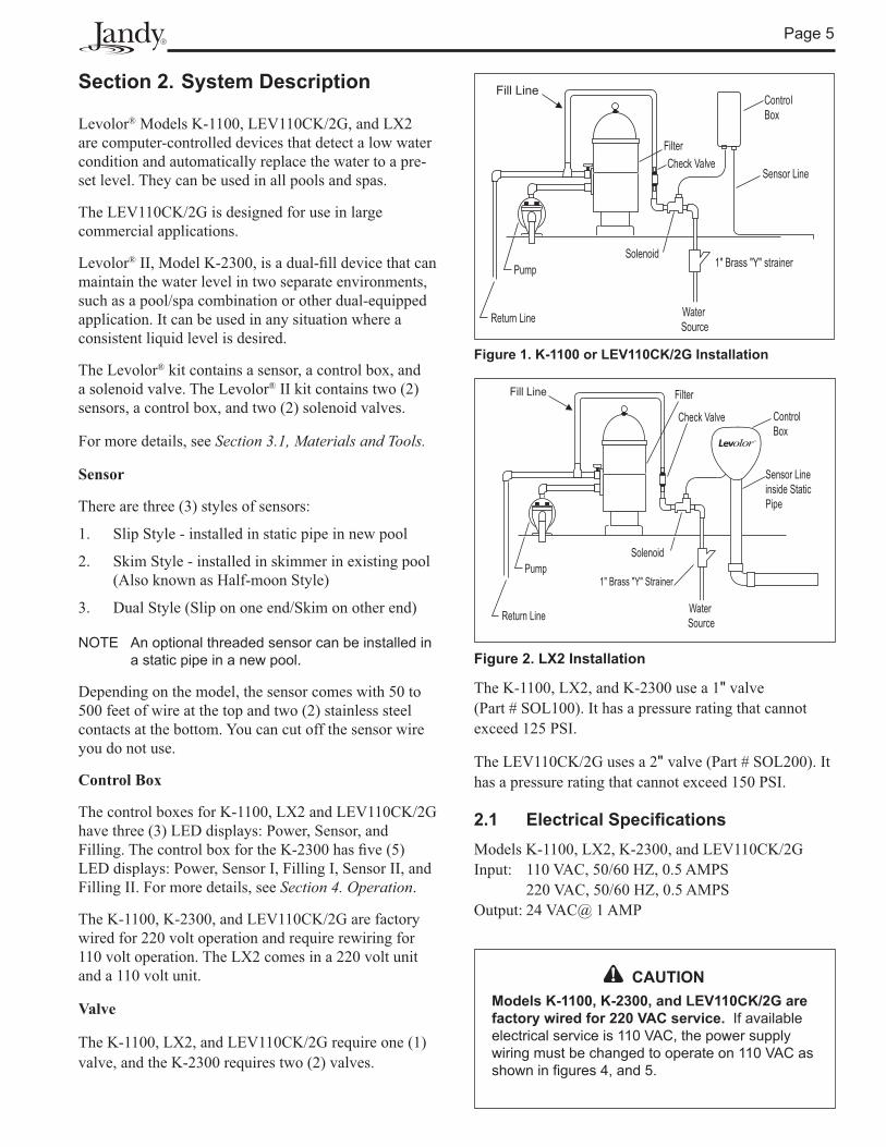
Section 2. System Description
Levolor® Models K-1100, LEV110CK/2G, and LX2 are computer-controlled devices that detect a low water condition and automatically replace the water to a pre-set level. They can be used in all pools and spas.
The LEV110CK/2G is designed for use in large commercial applications.
Levolor® II, Model K-2300, is a dual-� ll device that can maintain the water level in two separate environments, such as a pool/spa combination or other dual-equipped application. It can be used in any situation where a consistent liquid level is desired.
The Levolor® kit contains a sensor, a control box, and a solenoid valve. The Levolor® II kit contains two (2) sensors, a control box, and two (2) solenoid valves.
For more details, see Section 3.1, Materials and Tools.
Sensor
There are three (3) styles of sensors:
1. Slip Style - installed in static pipe in new pool
2. Skim Style - installed in skimmer in existing pool (Also known as Half-moon Style)
3. Dual Style (Slip on one end/Skim on other end)
NOTE An optional threaded sensor can be installed in a static pipe in a new pool.
Depending on the model, the sensor comes with 50 to 500 feet of wire at the top and two (2) stainless steel contacts at the bottom. You can cut off the sensor wire you do not use.
Control Box
The control boxes for K-1100, LX2 and LEV110CK/2G have three (3) LED displays: Power, Sensor, and Filling. The control box for the K-2300 has � ve (5) LED displays: Power, Sensor I, Filling I, Sensor II, and Filling II. For more details, see Section 4. Operation.
The K-1100, K-2300, and LEV110CK/2G are factory wired for 220 volt operation and require rewiring for 110 volt operation. The LX2 comes in a 220 volt unit and a 110 volt unit.
Valve
The K-1100, LX2, and LEV110CK/2G require one (1) valve, and the K-2300 requires two (2) valves.
Fill Line
Solenoid
Filter
Sensor Lineinside StaticPipe
ControlBox
Check Valve
Pump
Water Source
Fill Line
Return Line
1" Brass "Y" Strainer
Figure 1. K-1100 or LEV110CK/2G Installation
Figure 2. LX2 Installation
The K-1100, LX2, and K-2300 use a 1" valve (Part # SOL100). It has a pressure rating that cannot exceed 125 PSI.
The LEV110CK/2G uses a 2" valve (Part # SOL200). It has a pressure rating that cannot exceed 150 PSI.
2.1 Electrical Speci� cationsModels K-1100, LX2, K-2300, and LEV110CK/2GInput: 110 VAC, 50/60 HZ, 0.5 AMPS 220 VAC, 50/60 HZ, 0.5 AMPSOutput: 24 VAC@ 1 AMP
CAUTIONModels K-1100, K-2300, and LEV110CK/2G are factory wired for 220 VAC service. If available electrical service is 110 VAC, the power supply wiring must be changed to operate on 110 VAC as shown in figures 4, and 5.
Page 6
Solenoid Valve Wires (Blue Wires)
Transformer
Sensor Wires (Orange Wires)
Green Wire (Ground)
Black WireBlack Wire/White StripeBlack Wire/Red StripeBlack Wire/Yellow Stripe
Sensor
Orange Wires
Blue Wires
Three (3) Status Lights
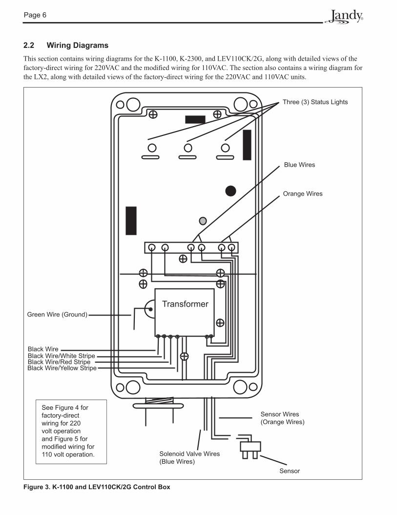
2.2 Wiring DiagramsThis section contains wiring diagrams for the K-1100, K-2300, and LEV110CK/2G, along with detailed views of the factory-direct wiring for 220VAC and the modi� ed wiring for 110VAC. The section also contains a wiring diagram for the LX2, along with detailed views of the factory-direct wiring for the 220VAC and 110VAC units.
Figure 3. K-1100 and LEV110CK/2G Control Box
See Figure 4 for factory-direct wiring for 220 volt operation and Figure 5 for modi� ed wiring for 110 volt operation.

Page 7
Gre
en
Transformer
1256
BLK
/RE
D
BLK
/WH
T
BLK BLK
/YE
L
Ground Line 1 Line 2
Figure 4. K-1100, K-2300, and LEV110CK/2G Factory Wiring for 220 Volt Operation
BLK
/RE
D
BLK
Gre
en
Transformer
1256
Ground Line Neutral
BLK
/WH
T
BLK
/YE
L
220 VoltOperation
110 VoltOperation
Figure 5. K-1100, K-2300, and LEV110CK/2G Modi� ed Wiring for 110 Volt Operation
Page 8
Front Inside ViewBack Inside View
High Power ½" ConduitValve ½" Conduit
Transformer Enclosure
PCBA
S 1
Transformer CaseB
Power
Blue Wires to SolenoidValve
Orange Wires to Sensor
24VAC
Black
Black220VAC or
Green(Ground)
Black110VAC
White
Connect to Orange Sensor Wires
Connect to Blue Solenoid Valve Wires
Connectto Solenoid Using Grease-Filled Wire Nuts
Black Green
Black
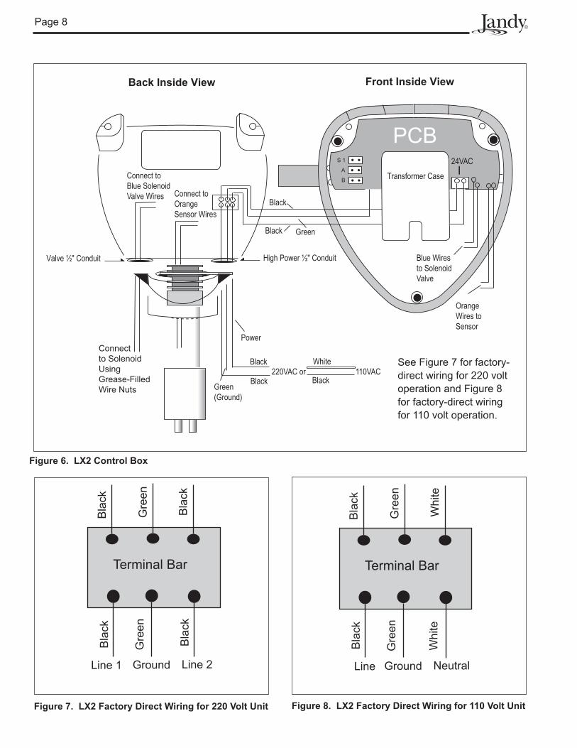
Figure 6. LX2 Control Box
See Figure 7 for factory-direct wiring for 220 volt operation and Figure 8 for factory-direct wiring for 110 volt operation.
Figure 7. LX2 Factory Direct Wiring for 220 Volt Unit Figure 8. LX2 Factory Direct Wiring for 110 Volt Unit
Gre
en
Terminal Bar
Bla
ck
Bla
ck
GroundLine 1 Line 2
Bla
ck
Gre
en
Bla
ck
Gre
en
Terminal Bar
Bla
ck
GroundLine Neutral
Bla
ck
Gre
en
Whi
teW
hite
Page 9
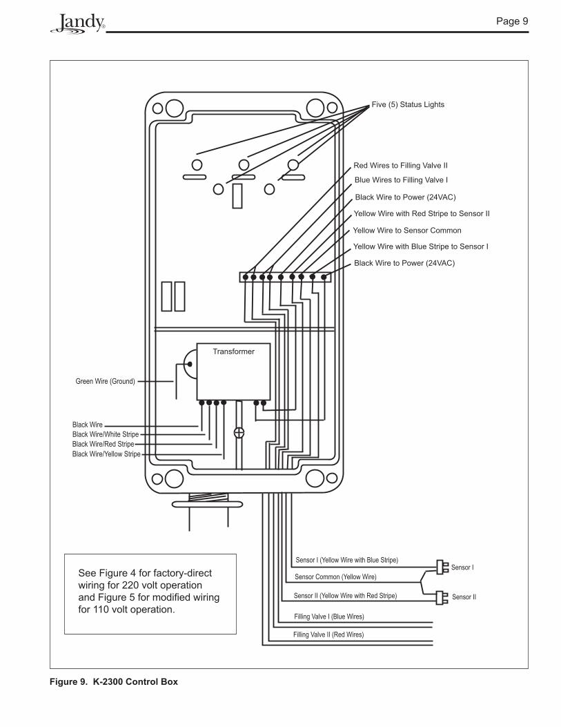
Transformer
Sensor I (Yellow Wire with Blue Stripe)
Five (5) Status Lights
Sensor II (Yellow Wire with Red Stripe)
Red Wires to Filling Valve II
Blue Wires to Filling Valve I
Black Wire to Power (24VAC)
Yellow Wire with Red Stripe to Sensor II
Yellow Wire with Blue Stripe to Sensor I
Black Wire to Power (24VAC)
Filling Valve II (Red Wires)
Filling Valve I (Blue Wires)
Yellow Wire to Sensor Common
Sensor Common (Yellow Wire) Sensor I
Sensor II
Black Wire/Red StripeBlack Wire/White Stripe
Black Wire/Yellow Stripe
Black Wire
Green Wire (Ground)
Figure 9. K-2300 Control Box
See Figure 4 for factory-direct wiring for 220 volt operation and Figure 5 for modi� ed wiring for 110 volt operation.

Page 10
Section 3. Installation Instructions
3.1 Materials and Tools
Installation Materials Supplied for Levolor® Models K-1100, LX2, or LEV110CK/2G
Qty
Sensor with Wire 1Solenoid Valve 1Coupler 1Control Box 1Remote Sensor Housing 1Hardware Kit 1 Grease-Filled Wire Nuts for Valve 2 per kit Screws 4 per kit Anchors 4 per kitOwner’s Manual - Warranty Information 1
Installation Materials Furnished for Levolor® II, Model K-2300
Qty
Sensor with Wire 2Solenoid Valve 2Coupler 2Control Box 1Remote Sensor Housing 2Hardware Kit 2 Grease-Filled Wire Nuts for Valve 2 per kit Screws 4 per kit Anchors 4 per kitOwner’s Manual - Warranty Information 1
Additional Materials Needed for InstallationDPST(Dual Pole Single Throw) 24VAC Relay with Contacts Properly Rated for Pump SelectedAnti-siphon Valve*2-Conductor, 18-Gauge Solid-Core Burial CableWire Nut Connectors for the Sensor, Relay, and Power Connections
*The anti-siphon valve is not necessary if the connection is made from the irrigation system.
Open the box and check to see that it contains the contents listed above. If it does not, contact your dealer or Jandy technical support at (707) 776-8200 extension 260.
3.2 Installing the Control Box
NOTE When installing a Levolor® on a spa (less than 300 sq ft of surface area), turn the flow control down to reduce the flow rate of the valve.
Models K-1100, K-2300, and LEV110CK/2G
1. Mount the control box to the wall near the pump and � lter. See Figure 1. Do not install the control box within 10 ft (3 m) of the pool edges.
2. Mount the control box at eye level. Leave suf� cient clearance on all sides of the chassis backplate.
3. Check the source voltage. (All three (3) units are factory wired for 220 volt operation.) To modify the wiring for 110 volt operation, see Section 3.3.
4. For 220 volt operation, connect the black wire to line 1 and connect the black wire with the yellow stripe to line 2. See Figure 4.
Model LX2
1. Mount the control box in the static pipe where the sensor is installed. See Figure 2.
2. Check the source voltage. (There are separate units for 220 and 110 volt operation.)
a. For 220 volt operation, connect one (1) of the black wires to line 1 and the other black wire to line 2. See Figure 7.
b. For 110 volt operation, connect the white wire to the white neutral line. Then connect the black wire to the black power line. See Figure 8.
Page 11
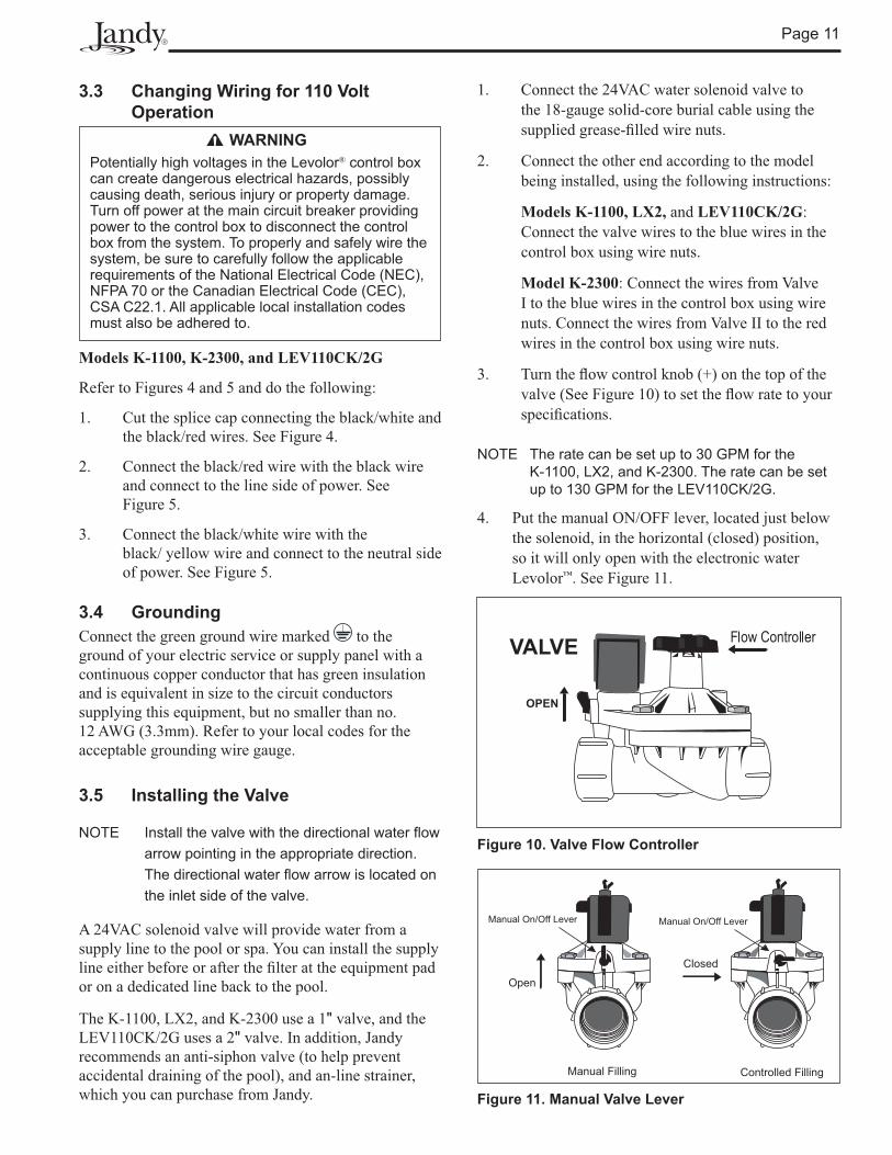
3.3 Changing Wiring for 110 Volt Operation
WARNINGPotentially high voltages in the Levolor® control box can create dangerous electrical hazards, possibly causing death, serious injury or property damage. Turn off power at the main circuit breaker providing power to the control box to disconnect the control box from the system. To properly and safely wire the system, be sure to carefully follow the applicable requirements of the National Electrical Code (NEC), NFPA 70 or the Canadian Electrical Code (CEC), CSA C22.1. All applicable local installation codes must also be adhered to.
Models K-1100, K-2300, and LEV110CK/2G
Refer to Figures 4 and 5 and do the following:
1. Cut the splice cap connecting the black/white and the black/red wires. See Figure 4.
2. Connect the black/red wire with the black wire and connect to the line side of power. See Figure 5.
3. Connect the black/white wire with the black/ yellow wire and connect to the neutral side of power. See Figure 5.
3.4 GroundingConnect the green ground wire marked to the ground of your electric service or supply panel with a continuous copper conductor that has green insulation and is equivalent in size to the circuit conductors supplying this equipment, but no smaller than no. 12 AWG (3.3mm). Refer to your local codes for the acceptable grounding wire gauge.
3.5 Installing the Valve
NOTE Install the valve with the directional water flow arrow pointing in the appropriate direction. The directional water flow arrow is located on the inlet side of the valve.
A 24VAC solenoid valve will provide water from a supply line to the pool or spa. You can install the supply line either before or after the � lter at the equipment pad or on a dedicated line back to the pool.
The K-1100, LX2, and K-2300 use a 1" valve, and the LEV110CK/2G uses a 2" valve. In addition, Jandy recommends an anti-siphon valve (to help prevent accidental draining of the pool), and an-line strainer, which you can purchase from Jandy.
Figure 10. Valve Flow Controller
Manual On/Off Lever Manual On/Off Lever
Manual Filling Controlled Filling
Closed
Open
Figure 11. Manual Valve Lever
1. Connect the 24VAC water solenoid valve to the 18-gauge solid-core burial cable using the supplied grease-� lled wire nuts.
2. Connect the other end according to the model being installed, using the following instructions:
Models K-1100, LX2, and LEV110CK/2G: Connect the valve wires to the blue wires in the control box using wire nuts.
Model K-2300: Connect the wires from Valve I to the blue wires in the control box using wire nuts. Connect the wires from Valve II to the red wires in the control box using wire nuts.
3. Turn the � ow control knob (+) on the top of the valve (See Figure 10) to set the � ow rate to your speci� cations.
NOTE The rate can be set up to 30 GPM for the K-1100, LX2, and K-2300. The rate can be set up to 130 GPM for the LEV110CK/2G.
4. Put the manual ON/OFF lever, located just below the solenoid, in the horizontal (closed) position, so it will only open with the electronic water Levolor™. See Figure 11.

Page 12
Figure 13. Skim (Half-moon) Sensor Retro� t Installation
Figure 14. Slip Sensor Installation
Cable
Mount Sensor with Velcro
Sensor
Sensor
Existing Water Level
Cable
Do Not SubmergeSensor UnderWater
TOP VIEW
SIDE VIEW
CableSensor
Sensor
Water Level
Do Not SubmergeSensor UnderWater
TOP VIEW
SIDE VIEW
Coupling
ExtensionPipe
Cable
Sensor Tips
3.6 Installing the Sensor
NOTE If using a dual style sensor, cut off and discard the sensor you are not planning to use. See Figure 12.
CAUTIONImportant Safety Instructions. Sensor wires must be continuous and not spliced. Solder all low voltage wire connections when possible and always use grease-filled wire nuts on low voltage connections.
1. Install the sensor in the appropriate location for the sensor style.
a. Mount the skim (half-moon) sensor horizontally to an existing skimmer. Mount with velcro or a suitable adhesive in the skimmer throat behind the whir door arc. See Figures 13 and 15.
b. Mount the slip sensor vertically in a static pipe. Glue the sensor to the coupling. See Figures 14 and 16.
NOTE Screw the optional threaded sensor into a 1" threaded coupling.
NOTE When using the static pipe method, glue all 1” fittings only. Do not glue 2” fittings. Glue all fittings with proper ABS/PVC glue: 793 IPS brand for ABS/PVC.
2. Connect the sensor wires as follows:
Models K-1100, LX2, and LEV110CK/2G: Connect the sensor cable to the two (2) orange wires in the control box using wire nuts. See Figures 3 and 6.
Model K-2300:
a. Connect one (1) wire from Sensor I and one (1) wire from the Sensor II to the yellow Sensor Common wire using wire nuts. See Figure 9.
b. Connect the other wire from Sensor I to the yellow wire with the blue stripe using wire nuts. See Figure 9.
c. Connect the other wire from Sensor II to the yellow wire with the red stripe using wire nuts. See Figure 9.
NOTE For all models, the wire to the sensors must be continuous. There cannot be any wire splices.
Skim Style Slip Style
Figure 12. Dual Style Sensor
Page 13
Levolor® Control Box
Houseor
Irrigation System
Returnto
Pool
Anti-siphon Valve
Check Valve
Sensor Probes
110-220VAC 24VAC
1' - 0
"
From CityWater Supplyvia DBL CHK VLV
Equip Room Floor Level
Operating Water Level
1" Brass "Y" Strainer
NOTE Install Line Level or Run Up-Hill From Pool to Prevent Air Lock
2" Stilling LineGrate Covered Wall Fittingor ½" Eye-Ball Fitting
1 ½" to Return Line
Solenoid Valve
OperatingWater Level
Levolor® K-1100 or LEV110CK/2G
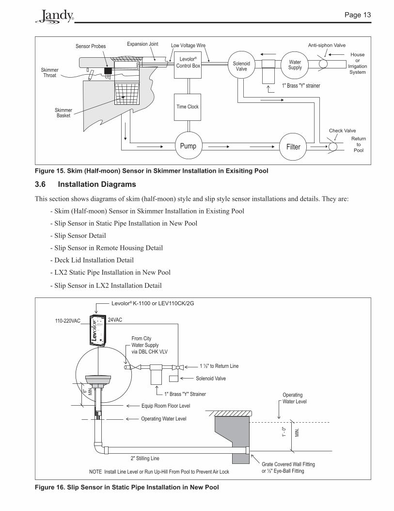
Figure 15. Skim (Half-moon) Sensor in Skimmer Installation in Exisiting Pool
Figure 16. Slip Sensor in Static Pipe Installation in New Pool
3.6 Installation Diagrams
This section shows diagrams of skim (half-moon) style and slip style sensor installations and details. They are:
- Skim (Half-moon) Sensor in Skimmer Installation in Existing Pool
- Slip Sensor in Static Pipe Installation in New Pool
- Slip Sensor Detail
- Slip Sensor in Remote Housing Detail
- Deck Lid Installation Detail
- LX2 Static Pipe Installation in New Pool
- Slip Sensor in LX2 Installation Detail
Page 14
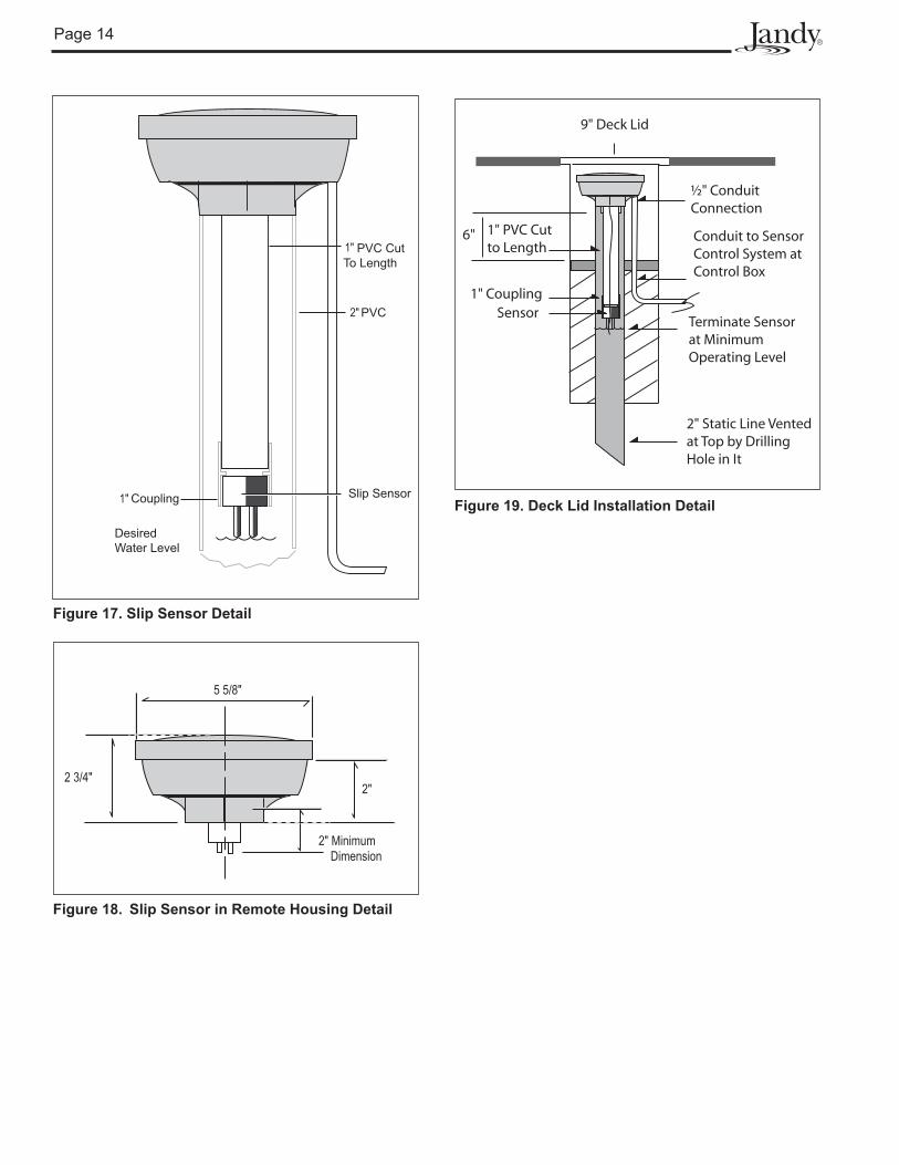
Desired Water Level
Slip Sensor
PVC CutTo Length
PVC
Coupling
Figure 17. Slip Sensor Detail
Figure 18. Slip Sensor in Remote Housing Detail
Sensor1" Coupling
½" Conduit Connection
1" PVC Cut to Length
2" Static Line Ventedat Top by DrillingHole in It
Terminate Sensorat Minimum Operating Level
Conduit to SensorControl System atControl Box
9" Deck Lid
6"
Figure 19. Deck Lid Installation Detail

Page 15
1' - 0
"
MIN.
Operating Water Level
6" MIN.
Equip Room Floor Level
From City Water Supply Via DBL CHK VLV
OperatingWater Level
2" Stilling Line
Levolor® Electronic Water Leveler
Grate Covered Wall Fittingor 1/2" Eye-Ball Fitting
1 ½" to Return Line
Solenoid Valve
DO NOT OPENNO USER SERVICEABLE PARTS INSIDE
Water Level Controller
24VAC
NOTE Install Line Level or Run Uphill From Pool to Prevent Air Lock
1" Brass "Y" Strainer
100-220VAC
Figure 20. LX2 in Static Pipe Installation in New Pool
Desired Water Level
1" Coupling Slip Sensor
1" PVC Cut to Length
2" PVC
DO NOT OPENNO USER SERVICEABLE PARTS INSIDE
Water Level Controller
2" Static LineVented Near Top by Drilling Hole in It
Figure 21. Slip Sensor in LX2 Installation Detail

Page 16
Section 4. Operation
4.1 K-1100, LEV110CK/2G, and LX2The controllers for the K-1100 and LEV110CK/2G (See Figure 22) and the LX2 (See Figure 23) each have three (3) lights. Refer to the � gures and Table 1.
Figure 22. K-1100 and LEV110CK/2G Controller Lights
Figure 23. LX2 Controller Lights
DO NOT OPENNO USER SERVICEABLE PARTS INSIDE
SENSORPWRFILL
Power Light Fill LightSensor Light
Power Light Sensor Light Filling Light
Power Sensor Filling
The Power light turns green when the unit is powered on. The Sensor light turns yellow when water is not touching the sensor tips.
The Filling light turns green 20 seconds after the sensor light illuminates, indicating that the valve is operational and � lling. The Filling light turns off when the pool is � lled.
The Filling light turns red when the unit enters Fill Safety Lockout Mode. This happens if it takes longer to � ll the pool than the time period allotted (20, 40, or 60 minutes). For more information, see Section 4.3, Fill Safety Lockout Mode.
NOTE The time period allotted for the LEV110CK/2G to fill is one, two, or three hours. See Table 1.
LED Function Color Operating Mode
Delay to Turn Function ON
Delay to Turn Function OFF
Power Turn Power ON Green Power is ON None None
Sensor Detect Low Water Yellow Water is Low None None
Filling forK-1100 and LX2
Filling Pool Green Fill Valve is ON
20 Seconds after Sensor Light
Turns ON
20 Seconds after Sensor Light Turns OFF
Safety Lockout Red Fill Valve is OFF 20, 40 or 60 Minutes 24 Hours
Filling forLEV110CK/2G
Filling Pool Green Fill Valve is ON
20 Seconds after Sensor Light
Turns ON
20 Seconds after Sensor Light Turns OFF
Safety Lockout Red Fill Valve is OFF 1, 2, or 3 Hours 24 Hours
Table 1. LED Indicators for K-1100, LX2, and LEV110CK/2G

Page 17
4.2 K-2300The controller for the K-2300 has � ve (5) lights. See Figure 24 and refer to Table 2.The Power light turns green when the unit is on. The Sensor I light turns yellow when water is not touching the Sensor I tips.
Twenty seconds later, the Filling I light turns green, indicating that Valve I is operational and � lling. The light turns off when the pool is � lled, and turns red when Valve I goes into Safety Lockout Mode.
Figure 24. K-2300 Controller Lights
ElectronicWater LevelorThe next generation in automated controls.SM
TM
II
Patented
High Voltage CompartmentNo user service parts inside
Model No. K-2300
Power Sensor I Filling I
Sensor II Filling IISensor I Filling I
Sensor II Filling II
Power
LED Function Color Operating Mode
Delay to Turn Function ON
Delay to Turn Function OFF
Power Turn Power ON Green Power is ON None None
Sensor I Detect Low Water in Pool Yellow Water in Pool
is Low None None
Filling IFilling Pool Green Fill I Valve is
ON20 Seconds after Sensor
Light Turns ON20 Seconds after Sensor
Light Turns OFF
Safety Lockout Red Fill I Valve is OFF 20, 40 or 60 Minutes 24 Hours
Sensor II Detect Low Water in Spa Yellow Water in Spa
is Low None None
Filling IIFilling Spa Green Fill II Valve is
ON20 Seconds after Sensor
Light Turns ON20 Seconds after Sensor
Light Turns OFF
Safety Lockout Red Fill II Valve is OFF 20, 40 or 60 Minutes 24 Hours
The Sensor II light turns yellow when water is not touching the Sensor II tips. Twenty seconds later, the Filling II light turns green, indicating that Valve II is operational and � lling. The light turns off when the spa is � lled, and it turns red when Valve II goes into Safety Lockout Mode.
Note that the K-2300 has two Safety Lockout features, one for Valve I and the other for Valve II. They operate independently. If one valve goes into Safety Lockout Mode, the other valve can continue to operate normally.
4.3 Fill Safety Lockout ModeThe Fill Safety Lock-out Mode shuts the Filling I or Filling II valve down for 24 hours or until the unit is powered down and back up to reset the � lling time. When the unit goes into lock-out, it indicates a possible problem with the control, sensor, or water � ll line system. The 24-hour window provides time to � nd and � x the problem. If the problem has not been � xed after 24 hours, the control will lock out for another 24 hours.
All four (4) models described in this manual are equipped with a lock-out sequence. This means that if the Levolor® sensor has not been touched by water within the pre-set Fill time period, the controller turns the valve off for 24 hours and changes the Filling I or Filling II light from green to red.
The pre-set factory Fill time for the K-1100, LX2, and K-2300 is 20 minutes, but it can be modi� ed to 40 or 60 minutes. The pre-set factory Fill time for the LEV110CK/2G is one hour, but it can be modi� ed to two or three hours. See Table 1 for pre-set and modi� ed Fill times. See Section 4.4 for instructions on modifying pre-set Fill times.
Table 2. LED Indicators for K-2300
Page 18
4.4 Fill Time before LockoutModel K-1100 and LX2:For the K-1100 and LX2 the factory-set Fill time before Safety Lockout occurs is 20 minutes. The Fill time can be modi� ed by cutting the jumpers as follows:
Cut Jumper Fill Time PeriodEither A or B 40 minute � ll before lockoutBoth A and B 60 minute � ll before lockout
NOTE To disable the lockout feature, cut jumper S-1.
See Figure 26 for the location of the LX2 jumpers and Figure 27 for the location of the K-1100 jumpers.
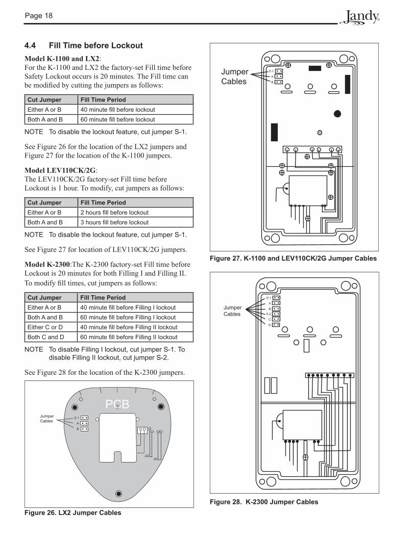
Model LEV110CK/2G:The LEV110CK/2G factory-set Fill time before Lockout is 1 hour. To modify, cut jumpers as follows:
Cut Jumper Fill Time PeriodEither A or B 2 hours � ll before lockoutBoth A and B 3 hours � ll before lockout
NOTE To disable the lockout feature, cut jumper S-1.
See Figure 27 for location of LEV110CK/2G jumpers.
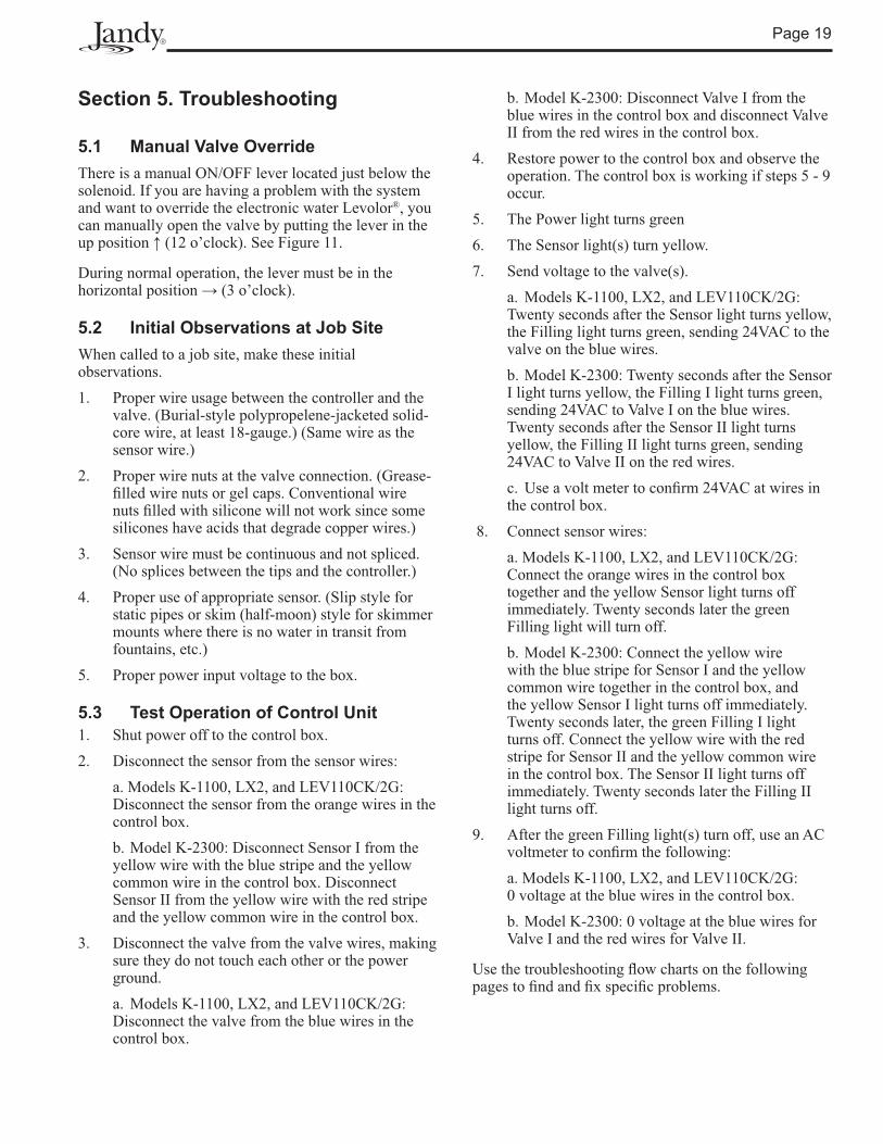
Model K-2300:The K-2300 factory-set Fill time before Lockout is 20 minutes for both Filling I and Filling II. To modify � ll times, cut jumpers as follows:
Cut Jumper Fill Time PeriodEither A or B 40 minute � ll before Filling I lockout Both A and B 60 minute � ll before Filling I lockoutEither C or D 40 minute � ll before Filling II lockoutBoth C and D 60 minute � ll before Filling II lockout
NOTE To disable Filling I lockout, cut jumper S-1. To disable Filling II lockout, cut jumper S-2.
See Figure 28 for the location of the K-2300 jumpers.
A
S 1
B
JumperCables
Figure 27. K-1100 and LEV110CK/2G Jumper Cables
Transformer Enclosure
PCBA
S 1
B
JumperCables
Figure 26. LX2 Jumper Cables
A
S 1
B
C
S 2
D
Jumper Cables
Figure 28. K-2300 Jumper Cables
Page 19
Section 5. Troubleshooting
5.1 Manual Valve OverrideThere is a manual ON/OFF lever located just below the solenoid. If you are having a problem with the system and want to override the electronic water Levolor®, you can manually open the valve by putting the lever in the up position � (12 o’clock). See Figure 11.
During normal operation, the lever must be in the horizontal position � (3 o’clock).
5.2 Initial Observations at Job SiteWhen called to a job site, make these initial observations.1. Proper wire usage between the controller and the
valve. (Burial-style polypropelene-jacketed solid-core wire, at least 18-gauge.) (Same wire as the sensor wire.)
2. Proper wire nuts at the valve connection. (Grease-� lled wire nuts or gel caps. Conventional wire nuts � lled with silicone will not work since some silicones have acids that degrade copper wires.)
3. Sensor wire must be continuous and not spliced. (No splices between the tips and the controller.)
4. Proper use of appropriate sensor. (Slip style for static pipes or skim (half-moon) style for skimmer mounts where there is no water in transit from fountains, etc.)
5. Proper power input voltage to the box.
5.3 Test Operation of Control Unit1. Shut power off to the control box.2. Disconnect the sensor from the sensor wires: a. Models K-1100, LX2, and LEV110CK/2G:
Disconnect the sensor from the orange wires in the control box.
b. Model K-2300: Disconnect Sensor I from the yellow wire with the blue stripe and the yellow common wire in the control box. Disconnect Sensor II from the yellow wire with the red stripe and the yellow common wire in the control box.
3. Disconnect the valve from the valve wires, making sure they do not touch each other or the power ground.
a. Models K-1100, LX2, and LEV110CK/2G: Disconnect the valve from the blue wires in the control box.
b. Model K-2300: Disconnect Valve I from the blue wires in the control box and disconnect Valve II from the red wires in the control box.
4. Restore power to the control box and observe the operation. The control box is working if steps 5 - 9 occur.
5. The Power light turns green6. The Sensor light(s) turn yellow.7. Send voltage to the valve(s). a. Models K-1100, LX2, and LEV110CK/2G:
Twenty seconds after the Sensor light turns yellow, the Filling light turns green, sending 24VAC to the valve on the blue wires.
b. Model K-2300: Twenty seconds after the Sensor I light turns yellow, the Filling I light turns green, sending 24VAC to Valve I on the blue wires. Twenty seconds after the Sensor II light turns yellow, the Filling II light turns green, sending 24VAC to Valve II on the red wires.
c. Use a volt meter to con� rm 24VAC at wires in the control box.
8. Connect sensor wires: a. Models K-1100, LX2, and LEV110CK/2G:
Connect the orange wires in the control box together and the yellow Sensor light turns off immediately. Twenty seconds later the green Filling light will turn off.
b. Model K-2300: Connect the yellow wire with the blue stripe for Sensor I and the yellow common wire together in the control box, and the yellow Sensor I light turns off immediately. Twenty seconds later, the green Filling I light turns off. Connect the yellow wire with the red stripe for Sensor II and the yellow common wire in the control box. The Sensor II light turns off immediately. Twenty seconds later the Filling II light turns off.
9. After the green Filling light(s) turn off, use an AC voltmeter to con� rm the following:
a. Models K-1100, LX2, and LEV110CK/2G: 0 voltage at the blue wires in the control box.
b. Model K-2300: 0 voltage at the blue wires for Valve I and the red wires for Valve II.
Use the troubleshooting � ow charts on the following pages to � nd and � x speci� c problems.
Page 20
Is fill light green or red?
YES NO
YES
YES
NONO
NOYES
YES
Pull sensor out of water.
Possible Issues:1. Manual lever on valve needs to be turned off. 2. Valve is dirty: take valve apart and clean inside.3. Diaphram is torn.4. LED light needs to be aligned with lens cover.
Possible Issues:1. Needs greased-filled wire nut at valve.2. Needs proper wire between controller and valve: solid- core 18-gauge wire with poly-pro jacket.3. Valve is bad.
Possible Issues:1. Needs greased-filled wire nut at valve.2. Needs proper wire between controller and valve: solid-core 18-gauge wire with poly-pro jacket.3. Valve is bad.
PCB board is bad.
Sensor is bad.
Does green fill light
turn off?
Does green fill light
turn off?
Is filllight on?
Disconnect blue valve wires from control box.
Does green fill light turn off?
Wait 20 seconds.
Disconnect orange sensor wires from control box
and touch them together.
Does sensorlight turn off?
Place sensorback in water.
Fill Will Not Turn OFF
Lockout sequence has taken effect.
Call technical support at(707) 776-8200 ext. 260.
GR
EEN
RED
NO
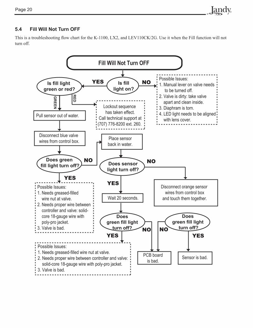
5.4 Fill Will Not Turn OFFThis is a troubleshooting � ow chart for the K-1100, LX2, and LEV110CK/2G. Use it when the Fill function will not turn off.
Page 21
Fill Will Not Turn ON
Disconnect orange sensor wires at
control box.
Is power light on?
Disconnect blue valvewires from control box.
Does green fill light
turn on?
Does green fill light
turn on?
Wait 20 seconds.
Does sensorlight turn on?
Transformer is bad.
Turn on power.
Sensor is bad.
Check blue wires with ACvoltmeter. Is there 24VAC?
Check for power at valve connection. Is there power?
PBC board is bad. Valve is bad.Cable connection betweenvalve and controller is bad.
Less power.
Verify correct input voltage to unit.
Pull sensor out of water.
Does sensorlight turn on?
YES
YES
YES
YES
YES
YES
YESNONO
NO
NO NO
NO
NODoes unit have power?
No power.
Lockout sequencehas taken effect.
Call technical support (707) 776-8200
ext 260. Is fill
light red?
NO
YES
YES NO
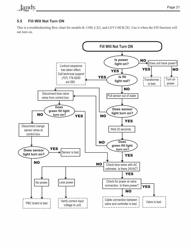
5.5 Fill Will Not Turn ONThis is a troubleshooting � ow chart for models K-1100, LX2, and LEV110CK/2G. Use it when the Fill function will not turn on.
Page 22
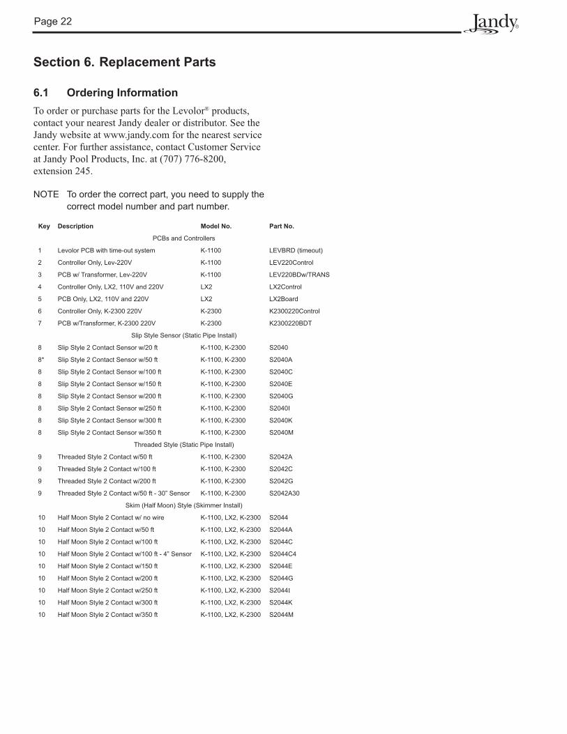
Key Description Model No. Part No.
PCBs and Controllers
1 Levolor PCB with time-out system K-1100 LEVBRD (timeout)
2 Controller Only, Lev-220V K-1100 LEV220Control
3 PCB w/ Transformer, Lev-220V K-1100 LEV220BDw/TRANS
4 Controller Only, LX2, 110V and 220V LX2 LX2Control
5 PCB Only, LX2, 110V and 220V LX2 LX2Board
6 Controller Only, K-2300 220V K-2300 K2300220Control
7 PCB w/Transformer, K-2300 220V K-2300 K2300220BDT
Slip Style Sensor (Static Pipe Install)
8 Slip Style 2 Contact Sensor w/20 ft K-1100, K-2300 S2040
8* Slip Style 2 Contact Sensor w/50 ft K-1100, K-2300 S2040A
8 Slip Style 2 Contact Sensor w/100 ft K-1100, K-2300 S2040C
8 Slip Style 2 Contact Sensor w/150 ft K-1100, K-2300 S2040E
8 Slip Style 2 Contact Sensor w/200 ft K-1100, K-2300 S2040G
8 Slip Style 2 Contact Sensor w/250 ft K-1100, K-2300 S2040I
8 Slip Style 2 Contact Sensor w/300 ft K-1100, K-2300 S2040K
8 Slip Style 2 Contact Sensor w/350 ft K-1100, K-2300 S2040M
Threaded Style (Static Pipe Install)
9 Threaded Style 2 Contact w/50 ft K-1100, K-2300 S2042A
9 Threaded Style 2 Contact w/100 ft K-1100, K-2300 S2042C
9 Threaded Style 2 Contact w/200 ft K-1100, K-2300 S2042G
9 Threaded Style 2 Contact w/50 ft - 30” Sensor K-1100, K-2300 S2042A30
Skim (Half Moon) Style (Skimmer Install)
10 Half Moon Style 2 Contact w/ no wire K-1100, LX2, K-2300 S2044
10 Half Moon Style 2 Contact w/50 ft K-1100, LX2, K-2300 S2044A
10 Half Moon Style 2 Contact w/100 ft K-1100, LX2, K-2300 S2044C
10 Half Moon Style 2 Contact w/100 ft - 4” Sensor K-1100, LX2, K-2300 S2044C4
10 Half Moon Style 2 Contact w/150 ft K-1100, LX2, K-2300 S2044E
10 Half Moon Style 2 Contact w/200 ft K-1100, LX2, K-2300 S2044G
10 Half Moon Style 2 Contact w/250 ft K-1100, LX2, K-2300 S2044I
10 Half Moon Style 2 Contact w/300 ft K-1100, LX2, K-2300 S2044K
10 Half Moon Style 2 Contact w/350 ft K-1100, LX2, K-2300 S2044M
Section 6. Replacement Parts
6.1 Ordering InformationTo order or purchase parts for the Levolor® products, contact your nearest Jandy dealer or distributor. See the Jandy website at www.jandy.com for the nearest service center. For further assistance, contact Customer Service at Jandy Pool Products, Inc. at (707) 776-8200, extension 245.
NOTE To order the correct part, you need to supply the correct model number and part number.

Page 23
Key Description Model No. Order Part No.
Dual Style (Skimmer or Static Pipe Install)
11 Dual Style Sensor w/50 ft K-1100, LX2, K-2300 S2046A
11 Dual Style Sensor w/100 ft K-1100, LX2, K-2300 S2046C
11 Dual Style Sensor w/150 ft K-1100, LX2, K-2300 S2046E
11 Dual Style Sensor w/200 ft K-1100, LX2, K-2300 S2046G
11 Dual Style Sensor w/250 ft K-1100, LX2, K-2300 S2046I
11 Dual Style Sensor w/300 ft K-1100, LX2, K-2300 S2046K
11 Dual Style Sensor w/350 ft K-1100, LX2, K-2300 S2046M
11 Dual Style Sensor w/400 ft K-1100, LX2, K-2300 S2046O
11 Dual Style Sensor w/450 ft K-1100, LX2, K-2300 S2046Q
11 Dual Style Sensor w/500 ft K-1100, LX2, K-2300 S2046S
Miscellaneous
12 Remote Sensor Cover and Lower Housing K-1100, LX2, K-2300 70010110
13 1” Plastic Valve, 24 V Soenoid w/Flow Control K-1100, LX2, K-2300 SOL100
14 1” Y Strainer K-1100, LX2, K-2300 BRY

This warranty is limited to the first retail purchaser, is not transferable, and does not apply to products that have been moved from their original installation sites. The liability of Jandy Pool Products, Inc. shall not exceed the repair or replacement of defective parts and does not include any costs for labor to remove and reinstall the defective part, transportation to or from the factory, or any other materials required to make the repair. Refrigerant or other expendables are not covered by the warranty. This warranty does not cover failures or malfunctions resulting from the following:
LIMITED WARRANTY
• AquaLink® RS units installed with Jandy Surge Protection Kits will be covered for two (2) years.• Never Lube® valves are warranted for the life of the pool and/or spa on which they were originally installed.• AquaPure® Electronic Chlorine Generator Electrolytic Cells carry a five (5) year limited warranty on a prorated basis.• Heat pumps are covered for two (2) years. There is a lifetime warranty on titanium tubing.• The heat pump compressor is covered for five (5) years.
1. Failure to properly install, operate, or maintain the product(s) in accordance with our pubished Installation, Operation and Maintenance Manuals, which are provided with the product(s).2. The workmanship of any installer of the product(s).3. Not maintaining a proper chemical balance in your pool and/or spa [pH levels between 7.2 and 7.8, with ideal ranges being between 7.4 and 7.6, Total Alkalinity (TA) between 80 to 120 ppm, Total Dissolved Solids (TDS) less than 2000, not including salt ppm].4. Abuse, alteration, accident, fire, flood, lightning, rodents, insects, negligence, or acts of God.5. Scaling, freezing, or other conditions causing inadequate water circulation.6. Operating the product(s) at water flow rates outside the published minimum and maximum specifications.7. Use of non-factory authorized parts or accessories in conjunction with the product(s).8. Chemical contamination of combustion air or improper use of sanitizing chemicals, such as introducing sanitizing chemicals upstream of the heater and cleaner hose or through the skimmer.9. Overheating; incorrect wire runs; improper electrical supply; collateral damage caused by failure of O-rings, DE grids, or cartridge elements; or damage caused by running the pump with insufficient quantities of water.
LIMITATION OF LIABILITY:This is the only warranty given by Jandy Pool Products, Inc. No one is authorized to make any other warranties on behalf of Jandy Pool Products, Inc. THIS WARRANTY IS IN LIEU OF ALL OTHER WARRANTIES, EXPRESSED OR IMPLIED, INCLUDING, BUT NOT LIMITED TO, ANY IMPLIED WARRANTIES OF FITNESS FOR A PARTICULAR PURPOSE AND MERCHANTABILITY. JANDY POOL PRODUCTS, INC. EXPRESSLY DISCLAIMS AND EXCLUDES ANY LIABILITY FOR CONSEQUENTIAL, INCIDENTAL, INDIRECT, OR PUNITIVE DAMAGES FOR BREACH OF ANY EXPRESSED OR IMPLIED WARRANTY. This warranty gives you specific legal rights. You may also have other rights that vary by state or province.
WARRANTY CLAIMS:For prompt warranty consideration, contact your dealer and provide the following information: proof of purchase, model number, serial number, and date of installation. The installer will contact the factory to obtain instructions regarding the claim and to determine the location of the nearest designated service center. If the dealer is not available, you can locate a service center in your area by visiting www.jandy.com or by calling our technical support department at 1.707.776.8200, extension 260. All returned parts must have a Returned Material Authorization number to be evaluated under the terms of this warranty.
Thank you for purchasing Jandy® pool and spa products. Jandy Pool Products, Inc. warrants all parts to be free from manufacturing defects in materials and workmanship for a period of one (1) year from the date of retail purchase, with the following exceptions:
H03
0360
0A
Jandy Pool Products, Inc.6000 Condor Drive, Moorpark, CA, USA 93021 • 707.776.8200 FAX 707.763.7785
Litho in USA © 2008 Jandy Pool Products, Inc. 0803
ETL LISTEDCONFORMS TO
UL STD 1563
CERTIFIED TOCAN/CSA C22.2 NO. 218.1