Pressure Side Pool Cleaner - PoolSupplyWorldedc.poolsupplyworld.com/wpdf/legendom.pdf · Pressure...
20
IMPORTANT SAFETY INSTRUCTIONS READ AND FOLLOW ALL INSTRUCTIONS SAVE THESE INSTRUCTIONS Installation Guide Pressure Side Pool Cleaner ®
-
Upload
trinhtuyen -
Category
Documents
-
view
218 -
download
2
Transcript of Pressure Side Pool Cleaner - PoolSupplyWorldedc.poolsupplyworld.com/wpdf/legendom.pdf · Pressure...

LEGEND® INSTALLATION MANUAL
IMPORTANT SAFETY INSTRUCTIONS
READ AND FOLLOW ALL INSTRUCTIONS
SAVE THESE INSTRUCTIONS
Installation Guide
Pressure Side Pool Cleaner
®

LEGEND® INSTALLATION MANUAL
Customer Service
If you have questions about ordering Pentair replacement parts, and pool products,
please use the following contact information:
Customer Service (8 A.M. to 5 P.M. — Eastern and Pacific Times)
Phone: (800) 831-7133
Fax: (800) 284-4151
Technical Support
Sanford, North Carolina (8 A.M. to 5 P.M. — Eastern Time)
Phone: (919) 566-8000
Fax: (919) 566-8920
Moorpark, California (8 A.M. to 5 P.M. — Pacific Time)
Phone: (805) 553-5000 (Ext. 5591)
Fax: (805) 553-5515
Web site
visit www.pentairpool.com and www.staritepool.com to find information about our products
© 2007 Pentair Water Pool and Spa, Inc. All rights reserved.
This document is subject to change without notice.
1620 Hawkins Ave., Sanford, NC 27330 • (800) 831-7133 • (919) 566-8000
10951 West Los Angeles Ave., Moorpark, CA 93021 • (800) 831-7133 • (805) 553-5000
Trademarks and Disclaimers. Pentair Water Pool and Spa and Legend are trademarks and/or registered trademarks of Pentair Water Pool and Spa, Inc.
Other trademarks and trade names may be used in this document to refer to either the entities claiming the marks and names or their products. Pentair
Water Pool and Spa, Inc. disclaims any proprietary interest in trademarks and trade names other than its own.
P/N 370270 REV. A00 12/13/07

LEGEND® INSTALLATION MANUAL
Important Information:
The Legend® automatic pool cleaner comes ready to connect into a female threaded 1-1/2" line, dedicated
to our Universal Booster Pump. Also, if you have a chlorinator, solar system or other air inducing equipment,
please contact our Technical Support Department at 1-800-831-7133, before you install the Legend®.
(See diagram on page 2.)
The following are important facts to remember before installing and operating the Legend®.
1. Always disconnect the Legend® from the pool wall when cleaning or back washing the pool filter.
2. After cleaning or back washing, let the filtration system run for at least five minutes before reconnecting
the Legend®.
3. New plumbing lines should be flushed out before installing the Legend®.
4. The Legend® should not be used to remove plaster dust in new pools.
5. Always remove the Legend® before swimmers enter the pool.
6. Always handle the Legend® with care. Do not let children or pets play with the unit: it is not a toy.
7. Always pick up the Legend® by the Vacuum Tube, especially when lifting the unit out of the water.
8. Unless checking the wheel RPM, do not handle the Legend® while it is operating.
9. Always remove the Legend® from the pool before chemical shock treatments. As a rule, any pool water
that is unsafe for swimming is unsafe for the Legend®.
10. Carefully cut the feed hose following the instructions on Page 3.
By following these simple guidelines, you can help protect against injury and prolong the life of your
Legend®.
Before the Legend® is installed, please take a moment to record the serial number. This number is located on
your warranty card and on the back of the Legend® near the rear jet. You will be asked for this number when
you contact our Technical Support Department.
SERIAL #__________________________________
LL505G
®

LEGEND® INSTALLATION MANUAL
TABLE OF CONTENTS
I. Introduction ................................................................................................................................ 1
A. Thank You for Choosing the Legend® ............................................................................... 1
B. What to Expect from the Legend® .................................................................................... 1
II. Installation Instructions .............................................................................................................. 2
A. Legend® Components ....................................................................................................... 2
B. Pool Connections ............................................................................................................. 2
C. Booster Pump Installation ................................................................................................ 2
D. Installing the Twist Lock Pressure Relief Valve (Wall Fitting) ............................................ 3
E. Cutting the Feed Hose...................................................................................................... 3
F. Checking Operation ......................................................................................................... 7
G. Fine Tuning the Legend® ................................................................................................... 7
1. Thrust Jet Adjustment ................................................................................................. 7
2. Sweep Hose Adjustment ............................................................................................. 7
3. Checking Wheel RPM ................................................................................................. 8
III. Operation & Periodic Maintenance ............................................................................................. 8
A. Connecting/Disconnecting the Legend® ............................................................................ 8
B. Turning the Legend® On/Off .............................................................................................. 8
C. Cleaning the Sand & Silt Bag ........................................................................................... 8
D. Periodic Maintenance ....................................................................................................... 9
1. Wall Fitting Screen ...................................................................................................... 9
2. Tires & Bearings ....................................................................................................... 10
3. Roller Rings .............................................................................................................. 10
4. Debris Bags .............................................................................................................. 10
5. Sweep Hose.............................................................................................................. 10
6. Debris Valve.............................................................................................................. 10
E. Back Washing the Pool Filter .......................................................................................... 10
F. Storage and Winterizing ................................................................................................. 10
G. Accessories ................................................................................................................... 11
1. Sweep Hose Weight .................................................................................................. 11
2. Leaf Bag ................................................................................................................... 11
3. Suction Cup Tires...................................................................................................... 11
IV. Troubleshooting ........................................................................................................................ 12
Legend® Parts List .............................................................................................................. 13
Legend® Exploded View ....................................................................................................... 15

LEGEND® INSTALLATION MANUAL
I. Introduction
A. Thank You for Choosing the
Legend® Pool Cleaner
Congratulations on the purchase of your new
automatic pool cleaner. The Legend® is designed to
give you years of dependable and efficient service.
With the Legend®, you and your family will spend
more time relaxing and enjoying your pool and less
time cleaning it.
The Legend® has been designed and built with time
proven features and patented innovations to create
an automatic pool cleaner that will give you years of
dependable service. The Legend® is built with pride
by people who care about the product using state of
the art materials and backed by a limited warranty
that protects against defects in parts and
construction.
Like any mechanical device, the Legend®
requires some preventative maintenance and the
replacement of certain hard working parts. We
recommend that you have your Legend® checked
annually. For best results have your Legend®
installed by a qualified swimming pool professional.
For pool owners with plumbing and mechanical
experience, installation instructions are included in
this manual.
Please put safety first! Be sure to take your
Legend® out of your pool and store it carefully in a
shaded area before anyone enters the pool.
B. What to Expect from the Legend®
When operating correctly, the Legend® will travel
randomly throughout the pool, vacuuming and
sweeping the bottom. The climbing ability of the
Legend® is dependent on the pools shape. It will
climb better in pools without sharp angles or curves
in the transition from the pool floor to the pool wall.
The Legend® comes equipped with a Wall Fitting
(Part# EW22) that features a Twist Lock Automatic
Pressure Relief Valve. If the Legend® is receiving
too much water pressure to the unit, the relief valve
can be manually adjusted to reduce water pressure.
Approximately every three minutes and 30 seconds
the Legend® will go into a back up mode. At this
time the Back Up Valve will pull the Legend® away
from it’s current location increasing it’s random
pattern.
The Sweep Hose operates in a gentle sweeping
motion to prevent debris from becoming trapped in
hard to reach corners of the pool.
1

LEGEND® INSTALLATION MANUAL
FROMPOOL
FILTERPUMP
POOLFILTER HEATER
SOLARSYSTEMCHLORINATORTO
POOL
BOOSTER PUMP
II. Installation Instructions
A. Legend® Components
The Legend® Box Contains:
1. Cleaner Head
2. Sand & Silt Bag
3. Sweep Hose (Attached to Cleaner Head)
4. Complete Feed Hose
a. 1 - 8½” hose
b. 2 - 10’ white (hard) hoses
c. 1 - 30” clear (soft) hose / 1 - 7.5’ clear (soft) hose
d. 10 - Floats
e. 3 - Swivels
f. 1 - Back-up Valve
g. 10 - Mender Nuts
h. 1 - Wall Fitting Complete
B. Pool Connections
The Legend® comes equipped to connect to a female
threaded 1-1/2" line, dedicated to our Universal
Booster Pump.
Also, if the pool doesn't have a dedicated cleaner
line, please contact our Technical Support
Department at 1-800-831-7133.
C. Booster Pump Installation
If you already have a 3/4 horsepower booster pump
installed at your equipment pad and it is operational,
skip this section and proceed to Installing the Twist
Lock Pressure Relief Valve (Wall Fitting).
Detailed booster pump installation instructions are
packaged separately in our booster pump box.
Please follow these instructions carefully.
The booster pump is not self-priming and needs to
be fed with water taken from the pool filter before
any type of in-line chlorinator. See figure below.
2
C D G
B G C
BDEB
A E D BH
D F
1
2
3
LEGEND® INSTALLATION MANUAL
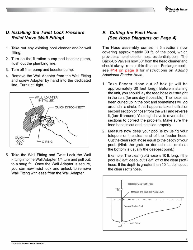
D. Installing the Twist Lock Pressure
Relief Valve (Wall Fitting)
1. Take out any existing pool cleaner and/or wall
fitting.
2. Turn on the filtration pump and booster pump,
flush out the plumbing line.
3. Turn off filter pump and booster pump.
4. Remove the Wall Adapter from the Wall Fitting
and screw Adapter by hand into the dedicated
line. Turn until tight.
5. Take the Wall Fitting and Twist Lock the Wall
Fitting into the Wall Adapter 1/4 turn and pull out;
to a snug fit. Once the Wall Adapter is secure,
you can now twist lock and unlock to remove
Wall Fitting with ease from the Wall Adapter.
E. Cutting the Feed Hose
(See Hose Diagrams on Page 4)
The Hose assembly comes in 5 sections now
covering approximately 30 ft. of the pool, which
provides ample hose for most residential pools. The
Back-Up Valve is now 30" from the head cleaner and
should always remain this distance. For larger pools,
see #14 on page 6 for instructions on Adding
Additional Feeder Hose.
1. Take Feeder Hose out of box (it will be
approximately 30 feet long). Before installing
the unit, you should lay the feed hose out straight
in the sun, (for one day if possible). The hose has
been curled up in the box and sometimes will go
around in a circle. If this happens, take the first or
second section of hose from the wall and reverse
it, (turn it around). You might have to reverse both
sections to correct the problem. Make sure the
feed hose is cut and installed properly.
2. Measure how deep your pool is by using your
telepole or the clear end of the feeder hose.
Cut the clear (soft) hose equal to the depth of your
pool. (Hint: the grate or domed main drain at
the bottom is usually the deepest point.)
Example: The clear (soft) hose is 10 ft. long, if the
pool is 8½ ft. deep, cut 1½ ft. off of the clear (soft)
hose. If the depth is greater than 10 ft., do not cut
the clear (soft) hose.
3
Deepest End of Pool
Telepole / Clear (Soft) Hose
Measure and Mark the Water Level
Main Drain
WALL ADAPTERINSTALLED
QUICKLOCKPEG
QUICK DISCONNECT
O-RING

LEGEND® INSTALLATION MANUAL
4
7½ FT.EXAMPLE DIMENSION
(Your Measurement May Differ)NOT TO SCALE
MARKED SWIVEL
FARTHEST POINT OF POOL PERIMETERFROM WALL FITTING
STEPS1. With the feed hose assembly attached to the pool wall, hold the feed hose assembly
by the opposite end with the clear hose and walk the perimeter of the pool to locatethe farthest point on the perimeter from the wall fitting without stretching the hose assembly.
2. Measure the distance that the hose assembly extends beyond the pool perimeterfarthest point located in Step 1 — (7½ ft. in this example).
3. Cut half of the length obtained from Step 2 — (3¾ ft. in this example),equally from each of the 10 foot lengths of white or grey hose on eitherside of the marked swivel.
10 FOOTWHITE OR GREYHOSE SECTION
10 FOOTWHITE OR GREYHOSE SECTION
10 FOOTSOFT HOSE
BACK UPVALVE
REMOVE EXCESS MATERIALFROM HOSE ON EITHER SIDE OFMARKED SWIVEL AS DESCRIBEDIN STEPS 2 AND 3.
WALL FITTING
SWIVEL
SWIVEL
FLOATS
FLOATS
FLOATS
EXAMPLE OF HOSE ASSEMBLYBEFORE CUTTING TO LENGTH
EXAMPLE OF FINISHED HOSE ASSEMBLYAFTER CUTTING TO LENGTH
WHITE OR GREYHARD HOSE SECTIONMARKED SWIVEL
END OFSOFT HOSE(End remains 30 in.)
SOFT HOSE(Cut to your pool depth)
BACK UP VALVE FURTHEST POINTOF POOL PERIMETERFROM WALL FITTING
STEPS4. Reassemble the hoses using the supplied mender nuts
as shown in FIGURE 1.
5. Your complete finished hose assembly should look like this.The end of the 30 inch clear hose should reach just to thefurthest edge of the pool perimeter as shown.
WHITE OR GREYHARD HOSE SECTION
FIGURE 1
WHITE OR GREYHARD HOSE SECTION(WALL FITTING SIDE)
WHITE OR GREYHARD HOSE SECTION(CLEANER SIDE)
MARKED SWIVEL

LEGEND® INSTALLATION MANUAL
E. Cutting the Feed Hose - (cont.)
3. Lay the telepole next to the clear (soft) hose. If
the clear (soft) hose is longer than the mark on
the telepole, cut the excess from the end attached
to the white (hard) hose. Do not cut off the float.
Leave the first float in position next to the
Back-Up Valve. Place the second float midway
between the first float and the Hose Swivel.
4. Attach feed hose to the wall fitting and attach wall
fitting to the pool wall. Hold the end of clear (soft)
hose and walk the perimeter of the pool keeping
the hose straight (do not stretch hose) to find the
farthest point of the pool from the wall fitting.
5. Measure the excess length between the farthest
point of the pool from Wall Fitting and the end of
30 in. clear (soft) hose.
6. Half of this measured length is to be cut
equally from 10 ft. white (hard) hoses next to
the Marked Swivel. (Example: Half of 6 ft. = 3 ft.
each). If you are cutting more than 2 ft. off the
hoses, remove the floats next to the Marked
Swivel from both hoses. See figures on page 4.
7. Re-assemble the hoses and the swivel using
mender nuts, see the Figure below. Put mender
nut on swivels first, then push hose over swivel,
rotate mender nut over hose clockwise until tight.
Note: Keep as many floats as possible on white
feed hoses spaced evenly apart to hold hose up
on top of water.
Water LevelWhite (Hard) HosesSwivel
Cut and Remove theExcess Hose Length
Cut Clear (Soft) Hose Equal tothe Deepest Pool Water Level
Telepole / Clear (Soft) Hose
5
FEEDHOSE
MENDERNUT
BARB ON SWIVELOR LEGEND
STEP 1
STEP 2
STEP 3
PUSH HOSE OVER BARB
PUSH MENDER NUT TOWARD HOSE AND ROTATECLOCKWISE BY HAND UNTIL TIGHT
SMALL ENDOF MENDERNUT AWAYFROM HOSE
LEGEND® INSTALLATION MANUAL
E. Cutting the Feed Hose - (cont.)
8. When cutting hoses, please use strong scissors
or a sharp knife. Be sure to slide the floats out of
the way when cutting hose.
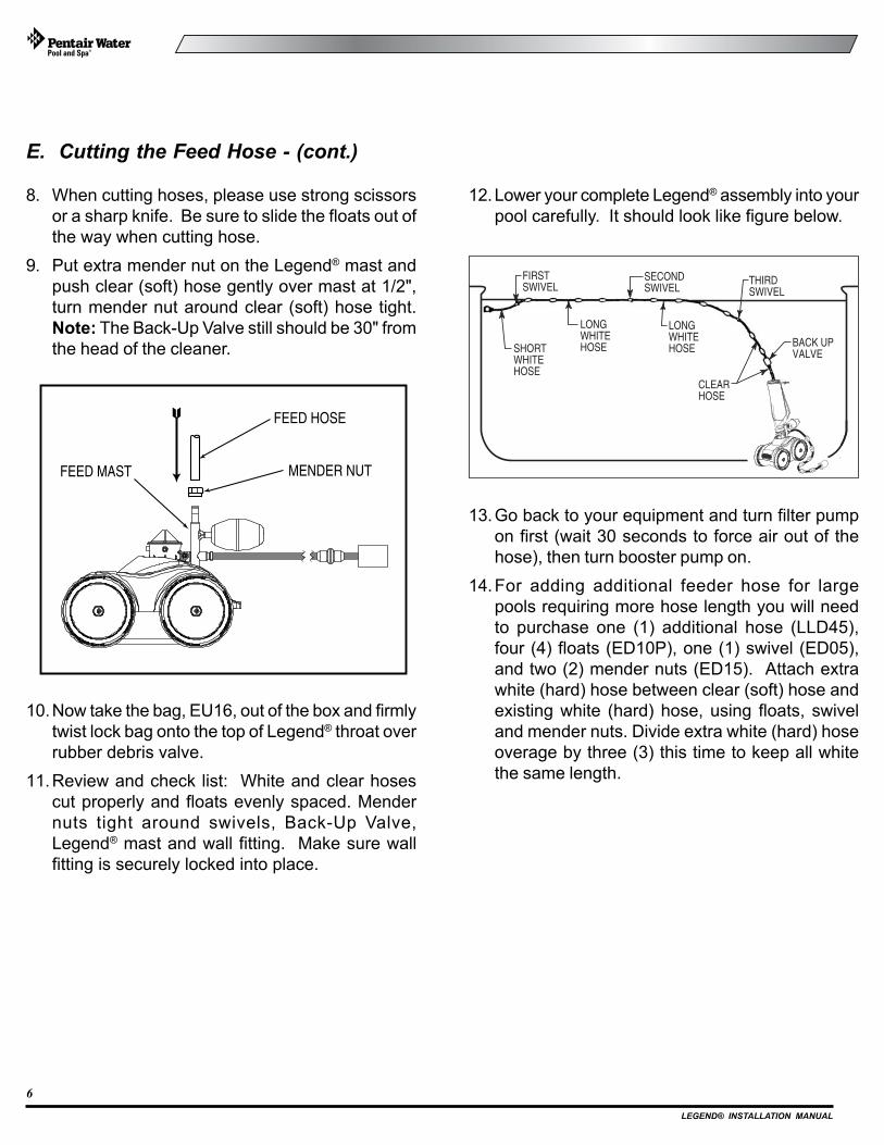
9. Put extra mender nut on the Legend® mast and
push clear (soft) hose gently over mast at 1/2",
turn mender nut around clear (soft) hose tight.
Note: The Back-Up Valve still should be 30" from
the head of the cleaner.
10.Now take the bag, EU16, out of the box and firmly
twist lock bag onto the top of Legend® throat over
rubber debris valve.
11.Review and check list: White and clear hoses
cut properly and floats evenly spaced. Mender
nuts tight around swivels, Back-Up Valve,
Legend® mast and wall fitting. Make sure wall
fitting is securely locked into place.
12.Lower your complete Legend® assembly into your
pool carefully. It should look like figure below.
13.Go back to your equipment and turn filter pump
on first (wait 30 seconds to force air out of the
hose), then turn booster pump on.
14.For adding additional feeder hose for large
pools requiring more hose length you will need
to purchase one (1) additional hose (LLD45),
four (4) floats (ED10P), one (1) swivel (ED05),
and two (2) mender nuts (ED15). Attach extra
white (hard) hose between clear (soft) hose and
existing white (hard) hose, using floats, swivel
and mender nuts. Divide extra white (hard) hose
overage by three (3) this time to keep all white
the same length.
6
FIRSTSWIVEL
SECONDSWIVEL
THIRDSWIVEL
SHORTWHITEHOSE
LONGWHITEHOSE
LONGWHITEHOSE BACK UP
VALVE
CLEARHOSE
FEED HOSE
MENDER NUTFEED MAST
LEGEND® INSTALLATION MANUAL
F. Checking Operation
When operating correctly, the Legend® will travel in
a random pattern throughout the pool, vacuuming
and sweeping the bottom. The climbing ability of the
Legend® is dependent on the pools structure and
water flow coming into the pool. It will perform more
efficiently in pools without sharp angles or curves in
the transition from the floor of the pool to the wall.
The Legend® comes with a Twist Lock Pressure
Relief Valve (Wall Fitting). If the Legend® is receiving
too much water pressure, the Relief Valve in the Wall
Fitting will release the excess water pressure.
Approximately every three minutes and 30 seconds
the Legend® will go into a back-up mode. The
Back-Up Valve cycle time, while in the back-up mode,
is approximately 30 seconds, pulling the Legend®
from it’s current location increasing it’s random
pattern.
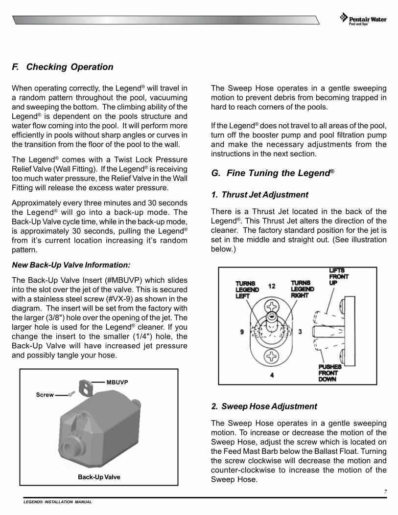
New Back-Up Valve Information:
The Back-Up Valve Insert (#MBUVP) which slides
into the slot over the jet of the valve. This is secured
with a stainless steel screw (#VX-9) as shown in the
diagram. The insert will be set from the factory with
the larger (3/8") hole over the opening of the jet. The
larger hole is used for the Legend® cleaner. If you
change the insert to the smaller (1/4") hole, the
Back-Up Valve will have increased jet pressure
and possibly tangle your hose.
7
The Sweep Hose operates in a gentle sweeping
motion to prevent debris from becoming trapped in
hard to reach corners of the pools.
If the Legend® does not travel to all areas of the pool,
turn off the booster pump and pool filtration pump
and make the necessary adjustments from the
instructions in the next section.
G. Fine Tuning the Legend®
1. Thrust Jet Adjustment
There is a Thrust Jet located in the back of the
Legend®. This Thrust Jet alters the direction of the
cleaner. The factory standard position for the jet is
set in the middle and straight out. (See illustration
below.)
Back-Up Valve
MBUVP
Screw
2. Sweep Hose Adjustment
The Sweep Hose operates in a gentle sweeping
motion. To increase or decrease the motion of the
Sweep Hose, adjust the screw which is located on
the Feed Mast Barb below the Ballast Float. Turning
the screw clockwise will decrease the motion and
counter-clockwise to increase the motion of the
Sweep Hose.

LEGEND® INSTALLATION MANUAL
III. Operation/Periodic Maintenance
A. Connecting/Disconnecting the
Legend®
Turn off the booster pump and pool pump. Then take
the Wall Fitting and twist lock the Wall Fitting
clockwise into the Wall Adapter. To disconnect the
Legend®, unlock and twist counter-clockwise. The
Wall Adapter should remain in the pool wall.
B. Turning On/Off the Legend®
The Legend® operates off the booster pump coming
from the equipment pad, and can be turned on or off
by merely turning on/off your booster pump time
clock.
C. Cleaning the Sand & Silt Bag
Carefully unlock the debris bag from the vacuum
tube. Use your thumb to push the "U" shaped snap
lock closure upward until it snaps open. Make sure
to swing it away from the opening. Open the bag and
remove debris.
If you have any additional questions, please
contact Pentair Water Pool and Spa, Inc.,
Technical Support Department at:1-800-831-7133,
Monday through Friday.
G. Fine Tuning the Legend®
3. Checking Wheel RPM
To determine whether the Legend® is receiving the
proper water pressure, turn off the pool pump, and
carefully remove the Legend® from the pool.
8
Mark the front drive Tire/Wheel with a marker, or
use the Pentair logo located on the side of tire as a
marker to count the rotations of the wheel per minute.
Have someone turn on pool pump and the booster
pump while you place the Legend® in the pool just
beneath the water surface. (Be sure to hold onto
the Sweep Hose to avoid getting wet).
Count the rotations of the marked wheel for exactly
one minute. (Be sure the Back-Up Valve isn't cycling
at this time). The rotations will give you the
Revolutions Per Minute. (RPM)
For proper performance, the Legend® operates
between 28-32 RPM. If the RPM is below 28 then
call your local Pool Professional or contact our
Technical Support Department at 1-800-831-7133.
If the RPM is more than 32, at the Wall Fitting, unscrew
the Pressure Relief Valve slowly until the RPM falls
between 28-32.
SWEEPHOSE
FRONTWHEELDRIVE
Push middle ofthe bag inwardfor closure.
OPEN
CLOSE
CLEANER BAG
"U" SHAPEDSNAP LOCKCLOSURE
OPEN
OPEN
To close, push the middle of bag inward, as shown,
and bring the edges together to make them stack like
an accordion. Swing the "U" shaped snap lock
closure back to the closing position.

LEGEND® INSTALLATION MANUAL
D. Periodic Maintenance
The following parts are wear items that should be
checked, maintained or replaced as needed. Wear
items are considered any working or moving part(s)
being worn due to the use of the cleaner. Wear items
are not covered under warranty.
1. Wall Fitting Screen
Inside the wall fitting is a filter screen that acts as a
secondary filter. This screen is to keep debris that is
passed by the pool filter out of the Legend®. Running
the Cleaner without the filter screen can damage the
Legend® and will void the warranty.
A continuous plugged or dirty screen is a sign of
problems in your pool filtration system and you need
to contact your local Pool Professional.
To clean the filter screen, pull the screen out from
inside the Wall Fitting and rinse thoroughly and push
back inside the Wall Fitting.
Whenever cleaning, back-washing or repairing the
filter, remove the Wall Fitting and flush out the
dedicated line before using the Legend®.
9
"U" SHAPEDSNAP LOCKCLOSURE
CLIP
Push down tosnap together.
CLEANER BAG
OPEN
OPEN
C. Cleaning the Sand & Silt Bag - (cont.)
Gently push on top of the "U" shaped snap lock
closure to make sure it snaps into place. Reattach
the clip onto the feed hose.
Your debris bag is ready to be reinstalled onto your
cleaner.
If you have a lot of debris in your pool, especially
after a storm, you can run your Legend® in two
shorter cycles per day and empty the debris bag
between cycles.
Reconnect the debris bag to the vacuum tube.
Do NOT over turn.
A Helpful Hint: It is easier to empty the debris bag
when it is dry. A second bag may be used while the
full debris bag is drying.
It's best to empty the debris bag when it becomes
half full. The Legend® will have better performance
if the bag is not overloaded.

LEGEND® INSTALLATION MANUAL
III. Operation/Periodic Maintenance -
(cont.)
2. Tires & Bearings
The tires are designed to protect the bottom of your
pool and provide better traction. You need to rotate
or replace the tires when the tire is worn up to the
wear groove.
The Wheel Bearings are warranted free of defects
when shipped from Pentair Water Pool and Spa, Inc.,
and are considered a wear item. A good bearing will
spin freely.
3. Roller Rings
Your Sweep Hose has a series of Roller Rings to
protect the Sweep Hose. Replace the rings as
needed. You can rotate the Roller Rings to prevent
flat spots.
4. Debris Bags
Fine Mesh Sand & Silt Bag
The Legend® comes with a Sand & Silt bag for
general use in all pools. We do not recommend using
the fine mesh bag to pick up leaves and twigs or other
large debris for they have sharp points and edges
that can poke holes and eventually rip the bag.
Optional Leaf Bag
The leaf bag is a larger mesh bag made to pick up
heavier debris such as leaves. twigs, acorns, etc.
This bag can be helpful especially after a storm.
A Helpful Hint: To prolong the life of bags, remove
the cleaner from pool before adding chemicals.
5. Sweep Hose
The Sweep Hose is provided to help keep the bottom
and sides of your pool clean. The Sweep Hose is
warranted free of defects when shipped from the
factory, and is considered a wear item.
6. Debris Valve
This valve is located under the Debris Bag, it is
designed to keep the debris inside the bag. It
functions like a check valve to allow the debris to
only enter through the bag one way. Replacement
is needed when valve begins to stiffen.
E. Back Washing the Pool Filter
Always disconnect the Legend® from the pool wall
before cleaning or back washing the pool filter.
After cleaning or back washing, let the pool filtration
system run for a minimum of five minutes to flush out
the return lines before reconnecting the Legend®.
F. Storage and Winterizing
Never leave or store the Legend® in direct sunlight.
When storing the Legend® for the winter, be sure to
drain all the water from it. This is important since
freeze damage is not covered under the warranty.
Also, remove the Wall Fitting.
10

LEGEND® INSTALLATION MANUAL
G. Accessories
1. Sweep Hose Weight
If the sweep hose tends to break the surface of the
water therefore squirting nearby windows or innocent
bystanders, a weight can be installed to the end of
the sweep hose.
(Part # for Hose Weight is EH09C)
2. Leaf Bag
(See previous page)
3. New Legend® Suction Cup Tires
Designed to climb in problem areas, fiberglass,
tile and smooth surfaces. For other applications,
please contact our Technical Service Department at
1-800-831-7133.
(Part # for Suction Cup Tires is LC6LSA)
11

LEGEND® INSTALLATION MANUAL
To insure the best performance from your cleaner,
follow the troubleshooting guide listed below.
IV. TROUBLESHOOTING AND PERFORMANCE TIPS
A. PROBLEMS & SOLUTIONS
Problem: Legend® doesn't move or moves sluggishly or hangs
up on steps.
Solution: 1. Be sure filter pump and booster pump are on and
working properly. (You may need to clean your
pool filter system).
2. Check the Wall Fitting screen for debris and
rinse clean.
3. Check wheel RPM, (see page 8).
4. Determine if the Back-Up Valve is cycling.
(Hold the valve out of the water and the jet
should come on for approx. 30 seconds and
shut off for approx. 3 minutes and 30 seconds.)
5. Check all the Hose connections and Swivels
for leaks that can cause loss of water pressure.
6. Check debris that may be jammed in the gear
teeth on one of the front drive wheels. Gently
rotate the front wheels backward to dislodge
debris.
Problem: Legend® falling over or lying on its side.
Solution: 1. This usually indicates the bag needs to be emptied.
2. Check to see if the ballast float (EA20) is leaking
by checking if there is water inside. Unscrew by
pulling back while turning counter-clockwise.
When it comes off, shake it and listen for water
in the float.
Problem: Legend® will not back up.
Solution: 1. Determine if the Back-Up Valve is cycling. (Hold
the valve out of the water and the jet should
come on for approx. 30 seconds, and shut off
for approx. 3 minutes and 30 seconds).
2. Check the wheel RPM, (see page 8).
3. Empty the debris bag if full or half full.
Problem: Legend® will not climb.
Solution: 1. Even if your pool doesn't show algae you still
need to brush the sides of the pool wall.
2. Check the wheel RPM, (see page 8).
3. Reposition the Thrust Jet. Loosen the two
screws to adjust the Thrust Jet, (see page 7).
12
A Reminder: The climbing ability of the Legend® is dependent on
the pool's shape and available water pressure. It will climb better
in pools without sharp angles or curves in the transition from the
pool floor to the pool wall.
Problem: Hoses tangling.
Solution: 1. Check the length of the Feed Hose, they may be
to long, (see pages 3-5).
2. Check to see that the Feed Hose is floating on
top of surface. Check hose floats for even
spacing.
3. Twist the Hose Swivels to see if they spin freely
and replace any that will not.
4. Lay out the Feed Hose straight in the full sun to
remove any memory.
Problem: Sweep Hose is sucked into the cleaner.
Solution: 1. Adjust the Sweep Hose using the Adjustment
Screw located on the bottom of the Swivel Mast
and just below the upper Thrust Jet. Turn
Adjustment Screw clockwise until the Sweep
Hose is in a gentle sweeping motion.
Problem: Booster Pump very noisy.
Solution: 1. Make sure Wall Fitting is mounted in
pool wall correctly.
2. Make sure Pool Filtration system is working properly.
3. Contact your local Pool Professional
-possible Booster Pump problem.
Problem: Sweep Hose breaks water surface and sprays
nearby windows, patio decks and bystanders.
Solution: 1. Adjust Sweep Hose to a gentle sweeping motion.
3. Add optional Sweep Hose weight, (see page 10).

LEGEND® INSTALLATION MANUAL
LEGEND® PARTS LIST
13
������ �� ��� ������ ����
� ������ ������� �
������� ���������� �
� ������ ���������� �
� ���� �������������!$��% �
� *+� �<�>����?����@K�Q��!����Z��� �
� *+� �<�>����@��[���
\ *+� �<�>����������%�
+ *]�� �<�>����@K�Q��@K��Z� �
^ *��� �<�>����������*Z>��� �
�� *� � �<�>����`���<���{����!�\|}�Z��%�K
�� *��� @�����{����!����Z��� �
� *��� @�����{����!�~����$��% ^
�� *� � @�����{����!��������ZZ�� �
�� �\��^+ @�����{����]��<�������@[��� �
�� *] � ��ZZ�����Z��� �
�� *{�\ @�����{����!�{����@Z���
�\ *��� ���������K���%���������Z�!������K���� �
�+ ����� ��������K���%�!���[K���[�Z���[� �
�+ *��� ��������K���%�!�`�Z[����������������� �
�^ *�^ ?�>����`�Z� �
� *�\ �!$��%�Q������������ �
� *�+ �!$��%�Q����K�<������ �
*��� �K�<������ �
� *��� �K�<�������!��Z��� �
� *�� ]�Z��!����%��~K��Z� �
� *\� ]�Z���Z��� �
� �\� �+� ]�Z��@[��������[��~��K�� +
\ ������ ~K��Z�����������%� �
+ *�� ~K��Z�������%��!���Z� +
^ *�� ~K��Z�@[����!��Z����[ �
�� *�� ��[�!<��`�Z� �
�� �����\ ~K��Z�!�$<>>������� �
� *��� {����Z��� �
�� *�� @[��� \
�� ������ {<>��� �

LEGEND® INSTALLATION MANUAL
14
LEGEND® PARTS LIST
SECOND 10'HOSE
FIRST 10'HOSE
30" CLEARHOSE
7.5' CLEARHOSE
35
������ �� ��� ������ ����
�� ��?�� �����{����!�Z����@�Q��!���� �
�� *?��� �Z����!������{��� ��
�\ ��?�� �����{����!�~K����!����
�+ *?�� @���Z�!������{���
�^ ����� ]�������{����!�~K����!�+�} �
�� *?�� ��������<��!��Z����[�!������{��� +
�� *~ ~�ZZ�������% �
� * � @[�����!�~�ZZ�������% �
�� * � �<�[��?��[����[��]������ �
�� *�� ~K��Z�!��Z����[�~��K�� �
� *{�^ @�����{����~��%K����������Z�!������K���� �
�� *��� ������Q�����[�!���`�Z� �
�\ *��� �K�<�������$�������������[Z<�����*�����*��������*�+ �
�+ *]�� @[����Q���*]�������*��� �
�^ �\���\ @�����{����!�@[�<>>�� �
�� *���\ @��������`�[��<>�������
�� *�\^ �<������Z��!��������������`�[��<>� �
� ���+ `���<�������
�� *�+� @[����!������������������� �
�� �����+ Z���{����Q�������� �

LEGEND® INSTALLATION MANUAL
LEGEND®
EXPLODED VIEW
SAVE THESE INSTRUCTIONS.
15
53
33
3
10
522 32
27
29
28
33
27
27
28
44
3431
29
33
48
32
10
18
17
3214
15
12
16
11
1349
9
6
1
28
26
50
5
8
6
204
51
32
48
19
50
21
2223 33
26
25
747
24
3431
54

LEGEND® INSTALLATION MANUAL
P/N 370270 REV. A00 12/13/07
© Pentair Water Pool and Spa, Inc. All rights reserved.