Installation and Operation - Hearth N...
64
Heatilator • Novus BV • 4031-551 Rev B • 12/06 1 Owner’s Manual Installation and Operation Models: NB3630/3933/4236/4842 NB3630I/3933I/4236I/4842I B-Vent Gas Appliance Installation and service of this appliance should be performed by qualified personnel. Hearth & Home Technologies suggests NFI certified or factory-trained professionals, or technicians supervised by an NFI certified professional. HOT! DO NOT TOUCH. SEVERE BURNS MAY RESULT. CLOTHING IGNITION MAY RESULT. WARNING • Keep children away. • CAREFULLY SUPERVISE children in same room as appliance. • Alert children and adults to hazards of high temperatures. • Do NOT operate with protective barriers removed or door open. • Keep clothing, furniture, draperies and other combustibles away. Glass and other surfaces are hot during operation and cool down. This appliance has been supplied with an integral barrier to prevent direct contact with the fixed glass panel. Do NOT operate the appliance with the barrier removed. Contact your dealer or Hearth & Home Technologies if the bar- rier is not present or help is needed to properly install one. This appliance may be installed as an OEM installation in manufactured home (USA only) or mobile home and must be installed in accordance with the manufacturer’s instructions and the manufactured home construction and safety standard, Title 24 CFR, Part 3280 or Standard for Installation in Mobile Homes, CAN/CSA Z240MH. This appliance is only for use with the type(s) of gas indicated on the rating plate. In the Commonwealth of Massachusetts: • installation must be performed by a licensed plumber or gas fitter. • a CO detector shall be installed in the room where the appliance is installed. DO NOT DISCARD THIS MANUAL CAUTION • Important operating and maintenance instructions included. • Leave this manual with party responsible for use and operation. • Read, understand and follow these instructions for safe installation and operation. DO NOT DISCARD If the information in these instruc- tions is not followed exactly, a fire may result causing property damage, personal injury, or death. • Do not store or use gasoline or other flam- mable vapors and liquids in the vicinity of this or any other appliance. • What to do if you smell gas: - Do not try to light any appliance. - Do not touch any electrical switch. Do not use any phone in your building. - Immediately call your gas supplier from a neighbor’s phone. Follow the gas supplier’s instructions. - If you cannot reach your gas supplier, call the fire department. • Installation and service must be performed by a qualified installer, service agency, or the gas supplier. WARNING
Transcript of Installation and Operation - Hearth N...

Heatilator • Novus BV • 4031-551 Rev B • 12/06 1
Owner’s ManualInstallation and Operation
Models:NB3630/3933/4236/4842NB3630I/3933I/4236I/4842IB-Vent Gas Appliance
Installation and service of this appliance should be performed by qualified personnel. Hearth & Home Technologies suggests NFI certifi ed or factory-trained professionals, or technicians supervised by an NFI certifi ed professional.
HOT! DO NOT TOUCH. SEVERE BURNS MAY RESULT.CLOTHING IGNITION MAY RESULT.
WARNING
• Keep children away. • CAREFULLY SUPERVISE children in same room as
appliance.• Alert children and adults to hazards of high
temperatures.• Do NOT operate with protective barriers removed or
door open.• Keep clothing, furniture, draperies and other
combustibles away.
Glass and other surfaces are hot during operation and cool down.
This appliance has been supplied with an integral barrier to prevent direct contact with the fi xed glass panel. Do NOT operate the appliance with the barrier removed.Contact your dealer or Hearth & Home Technologies if the bar-rier is not present or help is needed to properly install one.
This appliance may be installed as an OEM installation in manufactured home (USA only) or mobile home and must be installed in accordance with the manufacturer’s instructions and the manufactured home construction and safety standard, Title 24 CFR, Part 3280 or Standard for Installation in Mobile Homes, CAN/CSA Z240MH.This appliance is only for use with the type(s) of gas indicated on the rating plate.
In the Commonwealth of Massachusetts:• installation must be performed by a licensed plumber or gas fi tter.• a CO detector shall be installed in the room where the appliance is
installed.
DO NOT DISCARD THIS MANUALCAUTION
• Important operating and maintenance instructions included.
• Leave this manual with party responsible for use and operation.
• Read, understand and follow these instructions for safe installation and operation.
DO
NOT
DIS
CARD
If the information in these instruc-tions is not followed exactly, a fi re may result causing property damage, personal injury, or death.
• Do not store or use gasoline or other fl am-mable vapors and liquids in the vicinity of this or any other appliance.
• What to do if you smell gas:
- Do not try to light any appliance.- Do not touch any electrical switch. Do not
use any phone in your building.- Immediately call your gas supplier from
a neighbor’s phone. Follow the gas supplier’s instructions.
- If you cannot reach your gas supplier, call the fi re department.
• Installation and service must be performed by a qualifi ed installer, service agency, or the gas supplier.
WARNING

2 Heatilator • Novus BV • 4031-551 Rev B • 12/06
Read this manual before installing or operating this appliance.Please retain this owner’s manual for future reference.
Congratulations on selecting a Heatilator gas appliance—an elegant and clean alternative to wood burning appliances. The Heatilator gas appliance you have selected is designed to provide the utmost in safety, reliability, and effi ciency.As the owner of a new appliance, you’ll want to read and carefully follow all of the instructions contained in this owner’s manual. Pay special attention to all cautions and warnings.This owner’s manual should be retained for future reference. We suggest you keep it with your other important documents and product manuals.
The information contained in this owner’s manual, unless noted otherwise, applies to all models and gas control systems.Your new Heatilator gas appliance will give you years of durable use and trouble-free enjoyment. Welcome to the Heatilator family of appliance products!
Homeowner Reference Information
Model Name: Date purchased/installed:
Serial Number: Location on appliance:
Dealership purchased from: Dealer phone:
Notes:
We recommend that you record the following pertinent information about your appliance:
Listing Label Information/LocationThe model information regarding your specifi c appliance can be found on the rating plate located in the control area of the appliance.
XXXXCERTIFIED
FOR CANADACERTIFIÉ POUR LE
CANADA
Hearth & Home Technologies Inc1915 W. Saunders StreetMt. Pleasant, IA 52641
SERIALNO. DE SÉRIE
ANSI Standard
MODEL MFG. DATEMODÈLE DATE DE FAB.
GAS TYPE/TYPE DE GAZ NATURAL/NATUREL PROPANEALTITUDE 0-2000 2000-4000 FT/PI 0-2000 2000-4000 FT/PIMAX INPUT/DÉBIT XX,XXX XX,XXX BTUH XX,XXX XX,XXX BTUHMIN INPUT/DÉBIT XX,XXX XX,XXX BTUH XX,XXX XX,XXX BTUHMANIFOLD PRESSURE/PRESSION TUBULAIRE MAX. XX IN. W.C./C. D'EAU XX IN. W.C./C. D'EAU MIN. XX IN. W.C./C. D'EAU XX IN. W.C./C. D'EAUMIN. INLET PRESS. XX IN. W.C./C. D'EAU 1XX IN. W.C./C. D'EAUFOR THE PURPOSE OF INPUT ADJUSTMENTPRESS. MIN. D'ALIMENTATIONORIFICE SIZE DIAM. DE L'INJECTEUR XX/XX DIA. in./mm XX/XX DIA. in./mm
LESS THAN/MOINS DE 3 AMPÈRES., 115V., 60 Hz
DO NOT REMOVE OR COVER THIS LABEL.VENTED GAS FIREPLACE - NOT FOR USE WITH SOLID FUEL.FOYER À GAZ À ÉVACUATION - NE DOIT PAS ÊTRE UTILISÉ AVEC UN COMBUSTIBLE SOLIDE.
XXXXXXXXX
XXXXXX
Serial #Gas Type
OrificeSize
Model #
Congratulations

Heatilator • Novus BV • 4031-551 Rev B • 12/06 3
Table of Contents
1 Listing and Code Approvals 4A. Appliance Certifi cation . . . . . . . . . . . . . . . . . . . . . . . . . 4B. Glass Specifi cations . . . . . . . . . . . . . . . . . . . . . . . . . . 4C. BTU Specifi cations . . . . . . . . . . . . . . . . . . . . . . . . . . . 4D. High Altitude Installations . . . . . . . . . . . . . . . . . . . . . . 4E. Non-Combustible Materials . . . . . . . . . . . . . . . . . . . . . 4F. Combustible Materials . . . . . . . . . . . . . . . . . . . . . . . . . 4
2 Getting Started 5A. Design and Installation Considerations . . . . . . . . . . . . 5B. Negative Pressure . . . . . . . . . . . . . . . . . . . . . . . . . . . . 6C. Tools and Supplies Needed . . . . . . . . . . . . . . . . . . . . . 7D. Inspect the Appliance and Components . . . . . . . . . . . 7
3 Framing and Clearances 8A. Select Appliance Location . . . . . . . . . . . . . . . . . . . . . . 8B. Construct the Appliance Chase . . . . . . . . . . . . . . . . . . 9C. Clearances . . . . . . . . . . . . . . . . . . . . . . . . . . . . . . . . 10D. Mantel Projections . . . . . . . . . . . . . . . . . . . . . . . . . . . 11
4 Termination Locations 12A. Vent Termination Minimum Clearances . . . . . . . . . . . 12
5 Vent Information and Diagrams 13A. Vent Guidelines . . . . . . . . . . . . . . . . . . . . . . . . . . . . . 13B. Vent System Confi guration . . . . . . . . . . . . . . . . . . . . 13
6 Vent Clearances and Framing 15A. Pipe Clearances to Combustibles . . . . . . . . . . . . . . . 15B. Wall Penetration Framing . . . . . . . . . . . . . . . . . . . . . 15C. Vertical Penetration Framing . . . . . . . . . . . . . . . . . . . 15
7 Appliance Preparation 16A. Installing Outside Air Kit Damper Assembly . . . . . . . 16B. Gas and Electrical Connections . . . . . . . . . . . . . . . . 17C. Securing and Leveling Appliance . . . . . . . . . . . . . . . 17
8 Installing Vent Pipe 18A. Assemble Vent Sections . . . . . . . . . . . . . . . . . . . . . . 18B. Attach Vent to Firebox Assembly . . . . . . . . . . . . . . . 18C. Securing Vent Sections . . . . . . . . . . . . . . . . . . . . . . . 18
9 Gas Information 19A. Fuel Conversion . . . . . . . . . . . . . . . . . . . . . . . . . . . . 19B. Gas Pressure. . . . . . . . . . . . . . . . . . . . . . . . . . . . . . . 19C. Gas Connection . . . . . . . . . . . . . . . . . . . . . . . . . . . . . 19D. High Altitude Installations . . . . . . . . . . . . . . . . . . . . . 20
10 Electrical Information 21A. Recommendation for Wire . . . . . . . . . . . . . . . . . . . . . 21B. Connecting to the Appliance . . . . . . . . . . . . . . . . . . . 21C. Intellifi re Ignition System Wiring . . . . . . . . . . . . . . . . 21D. Standing Pilot Ignition System Wiring . . . . . . . . . . . . 22E. Junction Box Installation . . . . . . . . . . . . . . . . . . . . . . 23F. Wall Switch Installation for Fan (Optional) . . . . . . . . . 23
11 Finishing 24A. Mantel Projections . . . . . . . . . . . . . . . . . . . . . . . . . . . 24B. Facing Material . . . . . . . . . . . . . . . . . . . . . . . . . . . . . 24
12 Appliance Setup 25A. Remove the Shipping Materials. . . . . . . . . . . . . . . . . 25B. Clean the Appliance. . . . . . . . . . . . . . . . . . . . . . . . . . 25C. Accessories . . . . . . . . . . . . . . . . . . . . . . . . . . . . . . . . 25D. Install the Refractory . . . . . . . . . . . . . . . . . . . . . . . . . 25E. Lava Rock, Vermiculite, Rockwool Placement . . . . . 25F. Firescreen . . . . . . . . . . . . . . . . . . . . . . . . . . . . . . . . . 25G. Glass Assembly . . . . . . . . . . . . . . . . . . . . . . . . . . . . . 26H. Grilles and Trim . . . . . . . . . . . . . . . . . . . . . . . . . . . . . 26I. Hood . . . . . . . . . . . . . . . . . . . . . . . . . . . . . . . . . . . . . 26J. Air Shutter Setting . . . . . . . . . . . . . . . . . . . . . . . . . . . 27
13 Operating Instructions 28A. Before Lighting Appliance . . . . . . . . . . . . . . . . . . . . . 28B. Check Appliance Draft . . . . . . . . . . . . . . . . . . . . . . . . 29C. Lighting the Appliance . . . . . . . . . . . . . . . . . . . . . . . . 30D. After the Appliance is Lit . . . . . . . . . . . . . . . . . . . . . . 32E. Frequently Asked Questions . . . . . . . . . . . . . . . . . . . 32
14 Troubleshooting 33A. Standing Pilot Ignition System . . . . . . . . . . . . . . . . . . 33B. Intellifi re Ignition System . . . . . . . . . . . . . . . . . . . . . . 35
15 Maintaining and Servicing the Appliance 3716 Reference Materials 39
A. Appliance Dimension Diagram . . . . . . . . . . . . . . . . . 39B. Service Parts List. . . . . . . . . . . . . . . . . . . . . . . . . . . . 40C. Optional Components . . . . . . . . . . . . . . . . . . . . . . . . 56D. Limited Lifetime Warranty . . . . . . . . . . . . . . . . . . . . . 63E. Contact Information . . . . . . . . . . . . . . . . . . . . . . . . . . 64
Note: An arrow ( ) found in the text signifi es change in content.

4 Heatilator • Novus BV • 4031-551 Rev B • 12/06
1 1 Listing and Code Approvals
A. Appliance Certifi cation
This product is listed to ANSI standards for “Vented Gas Fireplaces” and “Gas Fired Appliances for Use at High Al-titudes”.
This model (natural gas and propane) can be installed in a bedroom (in the United States) which has a total volume of unconfi ned space appropriate to the particular installation. Refer to the National Fuel Gas Code ANSI Z223.1/NFPA54 (current edition), The Uniform Mechanical Code - (cur-rent edition), and local building offi cials for the options al-lowed in obtaining an effective bedroom volume of uncon-fi ned space.
This model (natural gas and propane) can be installed in a bedroom (in Canada) if a thermostat is installed with the ap-pliance. Consult local code authorities.
Do NOT use this appliance if any part has been under water. Immediately call a qualifi ed service technician to inspect the appliance and to replace any part of the control system and any gas control which has been under water.
WARNING
MODELS: NB3630/3933/4236/4842 NB3630I/3933I/4236I/4842ILABORATORY: Underwriters Laboratories, Inc. (UL)TYPE: B-Vent Gas Appliance STANDARD: ANSI Z21.88-2005/CSA2.33-2005
NOT INTENDED FOR USE AS A PRIMARY HEAT SOURCE. This appliance is tested and approved as either supplemental room heat or as a decorative appliance. It should not be factored as primary heat in residential heating calculations.
Note: This installation must conform with local codes. In the absence of local codes you must comply with the National Fuel Gas Code, ANSI Z223.1-latest edition in the U.S.A. and the CAN/CGA B149 Installation Codes in Canada.
B. Glass Specifi cationsHearth & Home Technologies appliances manufactured with tempered glass may be installed in hazardous locations such as bathtub enclosures as defi ned by the Consumer Product Safety Commission (CPSC). The tempered glass has been tested and certifi ed to the requirements of ANSI Z97.1 and CPSC 16 CFR 1202 (Safety Glazing Certifi cation Council SGCC# 1595 and 1597. Architectural Testing, Inc. Reports 02-31919.01 and 02-31917.01).
This statement is in compliance with CPSC 16 CFR Section 1201.5 “Certifi cation and labeling requirements” which refers to 15 U.S. Code (USC) 2063 stating “…Such certifi cate shall accompany the product or shall otherwise be furnished to any distributor or retailer to whom the product is delivered.”
C. BTU Specifi cations
D. High Altitude InstallationsU.L. Listed gas appliances are tested and approved without requiring changes for elevations from 0 to 2000 feet in the U.S.A. and Canada.
When installing this appliance at an elevation above 2000 ft, it may be necessary to decrease the input rating by chang-ing the existing burner orifi ce to a smaller size. Input rate should be reduced by 4% for each 1000 ft above a 2000 ft elevation in the U.S.A., or 10% for elevations between 2000 and 4500 ft in Canada. If the heating value of the gas has been reduced, these rules do not apply. To identify the prop-er orifi ce size, check with the local gas utility.
If installing this appliance at an elevation above 4500 ft (in Canada), check with local authorities.
Some local building codes require the use of tempered glass with permanent marking in such locations. Glass meeting this requirement is available from the factory. Please contact your dealer or distributor to order.
ModelMax Input
BTUHMin Input
BTUHOrifi ce
SizeNB3630 / NB3630I 20,000 14,000 .083
NB3933 / NB3933I 22,000 15,000 .089
NB4236 / NB4236I 25,000 17,000 .0935
NB4842 / NB4842I 30,000 20,500 .104
NB3630 (LP) 20,000 15,000 .052
NB3933 (LP) 22,000 15,000 .055
NB4236 (LP) 25,000 17,000 .058
NB4842 (LP) 30,000 20,500 .0635
E. Non-Combustible MaterialsMaterial which will not ignite and burn. Such materials are those consisting entirely of steel, iron, brick, tile, concrete, slate, glass or plasters, or any combination thereof.
Materials that are reported as passing ASTM E 136, Stan-dard Test Method for Behavior of Materials in a Vertical Tube Furnace at 750° C, shall be considered non-combus-tible materials.
F. Combustible MaterialsMaterials made of or surfaced with wood, compressed pa-per, plant fi bers, plastics, or other material that can ignite and burn, whether fl ame proofed or not, or whether plastered or unplastered shall be considered combustible materials.

Heatilator • Novus BV • 4031-551 Rev B • 12/06 5
A. Design and Installation ConsiderationsHeatilator B-vent gas appliances are designed to operate with all exhaust gases expelled to the outside of the building, and combustion air pulled from the room.
Check building codes prior to installation.• Installation MUST comply with local, regional,
state and national codes and regulations.• Consult insurance carrier, local building, fire
offi cials or authorities having jurisdiction about restrictions, installation inspection, and permits.
CAUTION
When planning an appliance installation, it’s necessary to determine the following information before installing:
• Where the appliance is to be installed. See Sections 3 and 4.
• The vent system confi guration to be used. See Sections 5 and 6.
• Gas supply piping. See Sections 7 and 9.• Electrical wiring. See Sections 7 and 10• Framing and finishing details. See Sections 3, 6
and 11.• Whether optional accessories—devices such as a fan, wall
switch, or remote control—are desired. See Section 16.
Keep appliance dry.• Mold or rust may cause
odors.• Water may damage controls.
WARNING
2 2 Getting Started
6 Heatilator • Novus BV • 4031-551 Rev B • 12/06
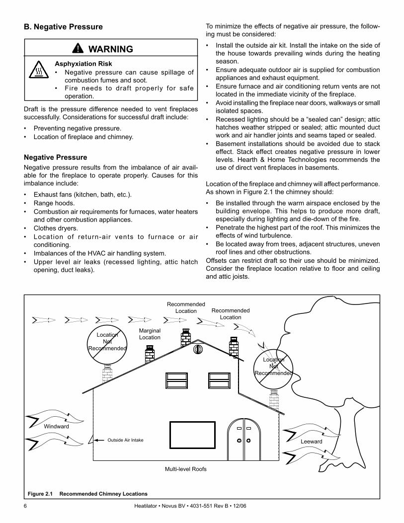
B. Negative Pressure
Asphyxiation Risk• Negative pressure can cause spillage of
combustion fumes and soot. • Fire needs to draft properly for safe
operation.
WARNING
To minimize the effects of negative air pressure, the follow-ing must be considered:
• Install the outside air kit. Install the intake on the side of the house towards prevailing winds during the heating season.
• Ensure adequate outdoor air is supplied for combustion appliances and exhaust equipment.
• Ensure furnace and air conditioning return vents are not located in the immediate vicinity of the fi replace.
• Avoid installing the fi replace near doors, walkways or small isolated spaces.
• Recessed lighting should be a “sealed can” design; attic hatches weather stripped or sealed; attic mounted duct work and air handler joints and seams taped or sealed.
• Basement installations should be avoided due to stack effect. Stack effect creates negative pressure in lower levels. Hearth & Home Technologies recommends the use of direct vent fi replaces in basements.
Location of the fi replace and chimney will affect performance. As shown in Figure 2.1 the chimney should:
• Be installed through the warm airspace enclosed by the building envelope. This helps to produce more draft, especially during lighting and die-down of the fi re.
• Penetrate the highest part of the roof. This minimizes the effects of wind turbulence.
• Be located away from trees, adjacent structures, uneven roof lines and other obstructions.
Offsets can restrict draft so their use should be minimized. Consider the fi replace location relative to fl oor and ceiling and attic joists.
Recommended Location
MarginalLocationLocation
NotRecommended
RecommendedLocation
Multi-level Roofs
Windward
LeewardOutside Air Intake
LocationNot
Recommended
Figure 2.1 Recommended Chimney Locations
Draft is the pressure difference needed to vent fi replaces successfully. Considerations for successful draft include:
• Preventing negative pressure.• Location of fi replace and chimney.
Negative PressureNegative pressure results from the imbalance of air avail-able for the fi replace to operate properly. Causes for this imbalance include:
• Exhaust fans (kitchen, bath, etc.).• Range hoods.• Combustion air requirements for furnaces, water heaters
and other combustion appliances.• Clothes dryers.• Locat ion of return-air vents to furnace or air
conditioning.• Imbalances of the HVAC air handling system.• Upper level air leaks (recessed lighting, attic hatch
opening, duct leaks).
Heatilator • Novus BV • 4031-551 Rev B • 12/06 7
Inspect appliance and components for damage. Damaged parts may impair safe operation.• Do NOT install damaged components.• Do NOT install incomplete components.• Do NOT install substitute components.Report damaged parts to dealer.
WARNING
Hearth & Home Technologies disclaims any responsibility for, and the warranty will be voided by, the following actions:
• Installation and use of any damaged appliance or vent system component.
• Modifi cation of the appliance or vent system.• Installation other than as instructed by Hearth & Home
Technologies.• Improper positioning of the gas logs or the glass
door.• Installation and/or use of any component part not
approved by Hearth & Home Technologies.
Any such action may cause a fi re hazard.
WARNING
C. Tools and Supplies NeededBefore beginning the installation be sure that the following tools and building supplies are available.
Reciprocating saw Framing materialPliers Hi temp caulking materialHammer GlovesPhillips screwdriver Framing squareFlat blade screwdriver Electric drill and bits (1/4 in.)Plumb line Safety glassesLevel ManometerVoltmeter Tape measureNon-corrosive leak check solution1/2 - 3/4 in. length, #6 or #8 Self-drilling screwsOne 1/4 in. female connection (for optional fan).
D. Inspect the Appliance and Components
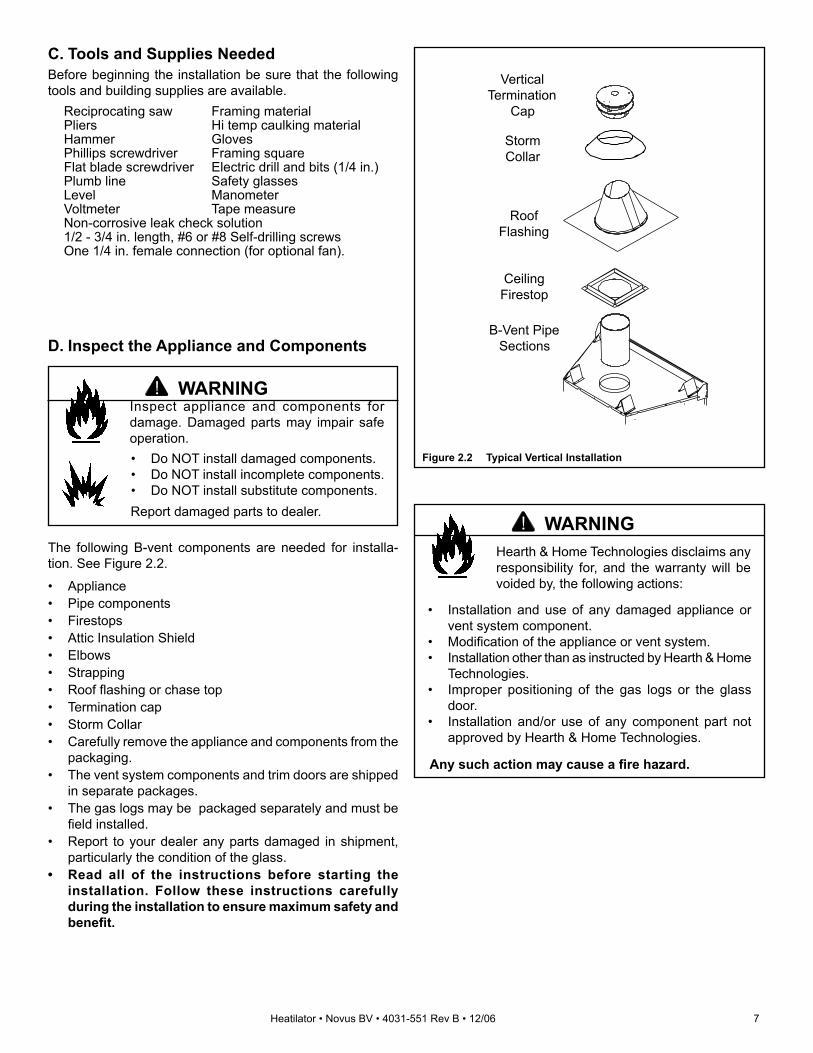
The following B-vent components are needed for installa-tion. See Figure 2.2.
• Appliance• Pipe components• Firestops• Attic Insulation Shield• Elbows• Strapping• Roof fl ashing or chase top• Termination cap• Storm Collar• Carefully remove the appliance and components from the
packaging. • The vent system components and trim doors are shipped
in separate packages. • The gas logs may be packaged separately and must be fi eld installed.
• Report to your dealer any parts damaged in shipment, particularly the condition of the glass.
• Read all of the instructions before starting the installation. Follow these instructions carefully during the installation to ensure maximum safety and benefi t.
VerticalTermination
Cap
RoofFlashing
CeilingFirestop
B-Vent PipeSections
StormCollar
Figure 2.2 Typical Vertical Installation

8 Heatilator • Novus BV • 4031-551 Rev B • 12/06
Note: • Illustrations refl ect typical installations and are FOR
DESIGN PURPOSES ONLY.• Illustrations/diagrams are not drawn to scale.• Actual installation may vary due to individual design
preference.
Fire RiskProvide adequate clearance:• Around air openings.• For service access.Locate appliance away from traffi c areas.
WARNING
A. Select Appliance LocationWhen selecting a location for your appliance it is important to consider the required clearances to walls (See Figure 3.1).
Note: For actual appliance dimensions refer to Section 16.
In addition to these framing dimensions, also reference the following sections:• Clearances and Mantel Projections (Sections 3.C. and 3.D.)• Vent Clearances and Framing (Section 6)
A
A
A
C
B
B
1/2 in. (13 mm) min.appliance
to combustibles
AlcoveInstallation
C
DDrywall48 in.
(1219 mm)max.
Figure 3.1 Appliance Locations
3 3 Framing and Clearances
Model A B C DNB3630 inches 36 33-1/2 19-5/8 37
mm 914 851 498 940
NB3933 inches 39 35-1/2 19-5/8 40
mm 991 902 498 1016
NB4236 inches 42 37-5/8 19-5/8 43
mm 1067 956 498 1092
NB4842 inches 48 41-7/8 19-5/8 49
mm 1219 1064 498 1245

Heatilator • Novus BV • 4031-551 Rev B • 12/06 9
B. Construct the Appliance ChaseA chase is a vertical boxlike structure built to enclose the gas appliance and/or its vent system. Vertical vents that run on the outside of a building may be, but are not required to be, installed inside a chase.
Construction of the chase may vary with the type of build-ing. These instructions are not substitutes for the require-ments of local building codes. Local building codes MUST be checked.
Chases should be constructed in the manner of all outside walls of the home to prevent cold air drafting problems. The chase should not break the outside building envelope in any manner.
Walls, ceiling, base plate and cantilever fl oor of the chase should be insulated. Vapor and air infi ltration barriers should be installed in the chase as per regional codes for the rest of the home. Additionally, Hearth & Home Technologies recom-mends that the inside surfaces be sheet rocked and taped (or the use of an equivalent method) for maximum air tight-ness.
To further prevent drafts gas line holes and other openings should be caulked with high temp caulk or stuffed with un-faced insulation. If the appliance is being installed on a ce-ment slab, we recommend that a layer of plywood be placed underneath to prevent conducting cold up into the room.
Fire Risk
• Construct chase to al l clearance specifi cations in manual.
• Locate and install appliance to all clearance specifi cations in manual.
WARNING
10 Heatilator • Novus BV • 4031-551 Rev B • 12/06
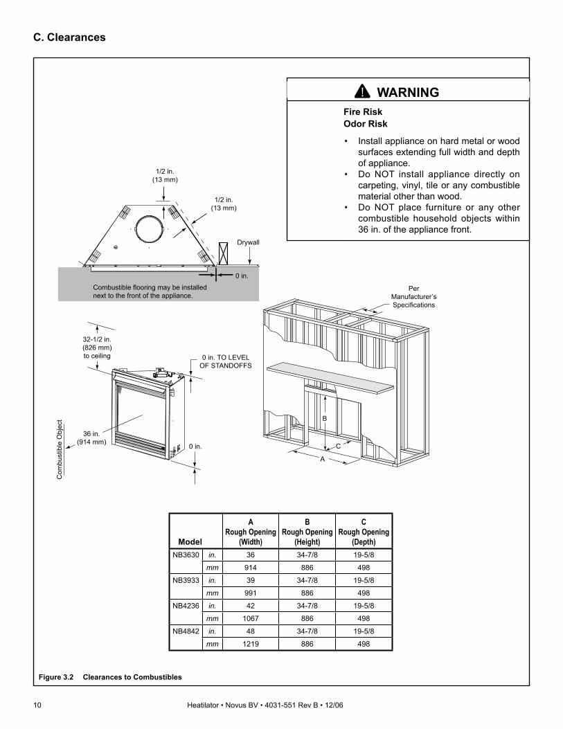
C. Clearances
PerManufacturer’sSpecifications
C
B
A
32-1/2 in.(826 mm)to ceiling
0 in.
0 in. TO LEVELOF STANDOFFS
1/2 in.(13 mm)
Drywall
0 in.
1/2 in.(13 mm)
Com
bust
ible
Obj
ect
36 in.(914 mm)
Combustible flooring may be installed next to the front of the appliance.
Figure 3.2 Clearances to Combustibles
Model
ARough Opening
(Width)
BRough Opening
(Height)
CRough Opening
(Depth)NB3630 in. 36 34-7/8 19-5/8
mm 914 886 498
NB3933 in. 39 34-7/8 19-5/8
mm 991 886 498
NB4236 in. 42 34-7/8 19-5/8
mm 1067 886 498
NB4842 in. 48 34-7/8 19-5/8
mm 1219 886 498
Fire RiskOdor Risk
• Install appliance on hard metal or wood surfaces extending full width and depth of appliance.
• Do NOT install appliance directly on carpeting, vinyl, tile or any combustible material other than wood.
• Do NOT place furniture or any other combustible household objects within 36 in. of the appliance front.
WARNING

Heatilator • Novus BV • 4031-551 Rev B • 12/06 11
Measured from top of hood (in inches)
34
56
78
910
1112
1314
1516
1718
55-1/2
6-1/47
7-3/48-1/2
9-1/410
10-3/411-1/2
12-1/413
13-3/414-1/2
15-1/416
32-1/2 in. minimumto ceiling
Figure 3.3 Clearances to Mantels or Other Combustibles Above Appliance
1 in. (25 mm) min.to perpendicular wall
A
3-1/2 in. (89 mm) min.from fireplace openingto perpendicular wall
B
48 in.(1219 mm)
max.
Mantel Leg or Perpendicular Wall
Top ofAppliance
Drywall
A
B
Figure 3.4 Clearances to Combustible Mantel Legs or Wall Projec-tions (acceptable on both sides of opening)
D. Mantel Projections
Fire Risk• Comply with all minimum clearances to combustibles as specifi ed.• Framing or fi nishing material used on the front of, or in front of, the appliance closer than the minimums
listed, must be constructed entirely of noncombustible materials (i.e., steel studs, concrete board, etc.).Failure to comply may cause fi re.
WARNING

12 Heatilator • Novus BV • 4031-551 Rev B • 12/06
A. Vent Termination Minimum Clearances
Fire RiskExplosion Risk
• Do not pack air space with insulation or other materials.
Maintain vent clearance to combustibles as specifi ed.
WARNING
Failure to keep insulation or other materials away from vent pipe may cause fi re.
Gas Termination Wood & Fuel Oil Termination A 6 in. (152 mm) 20 in. (508 mm)
Gas, Wood or FuelOil Termination
8 ft(2.44 m)
(minimum) toPerpendicular
Wall(gas only)
18 in.(457 mm)
A
GasTermination
Figure 4.2 Multiple Vertical Termination
Figure 4.1 specifi es minimum vent heights for various pitched roofs.
4 4 Termination Locations
12X
8 ft(2.44 m)
LowestDischargeOpening
TerminationCap
Roof Pitchis X / 12
Verticalwall
H (min.) - Minimum heightfrom roof to lowestdischarge opening.
Roof Pitch H (Min.) Ft. Roof Pitch H (Min.) Ft.Flat to 6/12 1.0* Over 11/12 to 12/12 4.0Over 6/12 to 7/12 1.25* Over 12/12 to 14/12 5.0Over 7/12 to 8/12 1.5* Over 14/12 to 16/12 6.0Over 8/12 to 9/12 2.0* Over 16/12 to 18/12 7.0Over 9/12 to 10/12 2.5 Over 18/12 to 20/12 7.5Over 10/12 to 11/12 3.25 Over 20/12 to 21/12 8.0
* 3 ft. minimum in snow regions
Storm Collar
RoofFlashing
Figure 4.1 Minimum Height from Roof to Lowest Discharge Opening

Heatilator • Novus BV • 4031-551 Rev B • 12/06 13
Fire RiskExplosion RiskAsphyxiation RiskDo NOT connect this gas appliance to a chimney fl ue serving a separate solid-fuel or gas burning appliance.• Vent this appliance directly outside.• Use separate vent system for this
appliance.May impair safe operation of this appliance or other appliances connected to the fl ue.
WARNING
ALL vent configuration specifications MUST be followed.• This product is tested and listed to appliance and
vent manufacturer’s specifi cations.• Appliance performance will suffer if specifi cations
are not followed.
CAUTION
Minimum clearances are
per vent manufacturer's specifications
Metal plumber's strap
secured to framing
Vent supports are per vent manufacturer's
specifications
9 ft (2.74 m) min.60 ft (18.29 m) max.
Figure 5.1 Vertical Termination Clearances
Maximum horizontal run is 50% ofvertical. Horizontal run cannot be
more than 30 ft. (9.14 m).
Vent supportsare per vent
manufacturer’sspecifications.
MetalPlumbers'
Strap
Figure 5.2 Maximum Horizontal Run
5 5 Vent Information and Diagrams
A. Vent Guidelines
Fire RiskAsphyxiation RiskThis appliance requires the specifi ed pipe
for operation.• Incorrect pipe may cause spillage,
condensation and overheating.
WARNING
These models require the following size B-Vent double wall vent pipe.
Model Pipe SizeNB3630/NB3630I/NB3933/NB3933I 5 in. (127 mm)
NB4236/NB4236I/NB4842/NB4842I 5 in. (127 mm)
• Follow pipe manufacturer’s installation guidelines when installing the appliance.
B. Vent System Confi guration• Rise to Run Ratio: 2:1• Maximum Total Horizontal Run: 30 ft (9.14 m)• Minimum Total Vertical Rise: 9 ft (2.74 m)• Maximum Total Vertical Rise: 60 ft (18.29 m)• Maximum Number of Elbows: Four 90° or Eight 45°

14 Heatilator • Novus BV • 4031-551 Rev B • 12/06
45°Elbow
90°Elbow
Offsets exceeding 45° adapt horizontal
limitations
Maximumhorizontal
30 ft (9.14 m)
Note: Maximum horizontal distance is 50% of vertical vent height.
Fire RiskExplosion RiskInsulation and other combustibles must not infringe on clearances.• ALWAYS maintain specifi ed clearances
around venting and fi restop systems.• Install fi restops as specifi ed.Failure to keep insulation or other material away from vent pipe may cause fi re.
WARNING
Figure 5.3 Maximum Horizontal Run

Heatilator • Novus BV • 4031-551 Rev B • 12/06 15
A. Pipe Clearances to Combustibles
Fire RiskExplosion RiskMaintain vent clearance to combustibles as specifi ed.• Do not pack air space with insulation or
other materials.• National building codes recommend
using attic shield to keep loose materials/insulation from contacting vent.
Failure to keep insulation or other materials away from vent pipe may cause fi re.
WARNING Do not pack with insulation or other materials.
Use manufacturer's installation instructions for framing dimensions
Figure 6.1 Exterior Wall Hole
6 6 Vent Clearances and Framing
B. Wall Penetration Framing
Follow vent pipe manufacturer’s instructions for all clear-ances around pipe.
For a wall penetration consult B-vent pipe manufacturer’s instructions. Use same dimensional framing materials as those used in the wall construction.
Note: MUST terminate vertically.
C. Vertical Penetration FramingUse B-vent manufacturer’s fi restops to provide adequate clearances.
Fire RiskKeep loose materials or blown insulation
from touching the vent pipe.• National building codes recommend
using attic shield to keep loose materials/insulation from contacting vent.
• Hearth & Home Technologies requires the use of an attic shield.
WARNING

16 Heatilator • Novus BV • 4031-551 Rev B • 12/06
7 7 Appliance Preparation
Sharp Edges• Wear protective gloves
and safety glasses during installation.
CAUTION
Fire RiskAsphyxiation RiskMaintain vent clearance to combustibles as specifi ed.• Do not pack air space with insulation or
other materials.• National building codes recommend
using attic shield to keep loose materials/insulation from contacting vent.
Failure to keep insulation or other materials away from vent pipe may cause fi re.
WARNING
A. Installing Outside Air Kit Damper Assembly
This appliance will operate correctly only if adequate ventia-tion is provided to allow proper draft to the system.
An outside air kit is available as an optional feature with this appliance. An outside air kit helps to decrease the amount of room air taken by utilizing outside air for combustion. We strongly recommend that it be installed.
Outlet placedhigher than 3 ft
below thetermination cap
Attic space
Garage orcombustible
liquids storageOutlet blocked bysnow, leaves, etc.
Clear area outside
house or in ventilated
crawl space
YES
NONO
NO
NO
Use only duct materials specifiedby manufacturer (preferably withshort run or mainly straight duct,except small dip for cold air trapwhich will help prevent flow of cold air).
Factory-builtfireplace
Figure 7.2 Outside Combustion Air Placement
Figure 7.1 Outside Air Kit Installation
• The outside air kit can only be installed on the left side of the appliance.
• Refer to the installation instructions provided with the kit.
Note: the outside air kit inlet thimble should be positioned in a manner that will not allow snow, leaves, etc. to block the inlet. A 3 ft. (.91 m) minimum height difference must be maintained from the top of the uppemost chimney section to the outside combustion air inlet. Reference Section 2.
Fire RiskAsphyxiation RiskDo not draw outside combustion air from:• Wall, fl oor or ceiling cavity.• Enclosed space such as an attic or
garage.• Close proximity to exhaust vents or
chimneys.Fumes or odor may result.
WARNING
Risk of Smoke SpillageOutside air inlet must be located to prevent blockage from: • Leaves • Snow/ice • Other debrisBlockage may cause combustion air starvation.
CAUTION

Heatilator • Novus BV • 4031-551 Rev B • 12/06 17
B. Gas and Electrical ConnectionsEnsure that gas and electrical connections are installed at this time. Refer to Sections 9 and 10.
Note: Once appliance is set up for top or rear venting, it CANNOT be changed at a later time.
Do NOT notch into the framing around the appliance spacers.
CAUTION
Nailing Flanges(both sides)
Figure 7.3 Proper Positioning, Leveling and Securing of an Appliance
C. Securing and Leveling Appliance
The diagram shows how to properly position, level, and se-cure the appliance (see Figure 7.3). Nailing tabs are pro-vided to secure the appliance to the framing members.
• Place the appliance into position. • Level the appliance from side to side and front to back.• Shim the appliance as necessary. It is acceptable to use
wood shims.• Bend out nailing tabs on each side.• Keep nailing tabs fl ush with the framing.• Secure the appliance to the framing by using nails or
screws through the nailing tabs.
Fire Risk!• Prevent contact with sagging, loose
insulation.• Do NOT install against combustible
materials such as exposed insulation, plastic and insulation backer.
WARNING

18 Heatilator • Novus BV • 4031-551 Rev B • 12/06
Tabs
A. Assemble Vent SectionsThis B-Vent appliance requires 5 in. B-vent double-wall pipe. Follow the pipe manufacturer’s installation guidelines when installing the appliance. This will ensure proper operation and prevent safety hazards.
8 8 Installing Vent Pipe
Fire RiskExhaust Fumes RiskImpaired Performance of Appliance.• Assemble pipe sections per B-Vent
manufacturer’s instructions.• Use support tabs for screws.• Screws must not exceed 1 in. long and
must not penetrate inner lining.• Pipe may separate if not properly
joined.
WARNING
Figure 8.1 Attaching Vent to Firebox
B. Attach Vent to Firebox AssemblyThree tabs extend from appliance collar shield. Attach tabs to fi rst section of B-vent pipe using self-tapping 1/4 in. screws supplied with appliance. See Figure 8.1.
C. Securing Vent SectionsSecure vent sections with vent supports following B-vent manufacturer’s instructions.
Fire RiskExplosion RiskAsphyxiation RiskUse vent run supports per vent manufacturer’s installation instructions.Connect vent sections per vent manufacturer’s
installation instructions.• Maintain all clearances to combustibles.• Maintain specifi ed slope (if required).Improper support may allow vent to sag or separate.
WARNING
Heatilator • Novus BV • 4031-551 Rev B • 12/06 19
A. Fuel ConversionBefore making gas connections ensure appliance being in-stalled is compatible with the available gas type.
Any natural or propane gas conversions necessary to meet the appliance and locality needs must be made by a quali-fi ed technician using Hearth & Home Technologies specifi ed and approved parts.
B. Gas PressureProper input pressures are required for optimum appliance performance. Gas line sizing requirements need to be made following NFPA51.
C. Gas Connection
Refer to Reference Section 16 for location of gas line access in appliance.
Note: Have the gas supply line installed in accordance with local building codes, if any. If not, follow ANSI 223.1. Installation should be done by a qualifi ed installer approved and/or licensed as required by the locality. (In the Commonwealth of Massachusetts installation must be performed by a licensed plumber or gas fi tter.)
Note: A listed (and Commonwealth of Massachusetts approved) 1/2 in. (13 mm) T-handle manual shut-off valve and fl exible gas connector are connected to the 1/2 in. (13 mm) control valve inlet.
• If substituting for these components, please consult local codes for compliance.
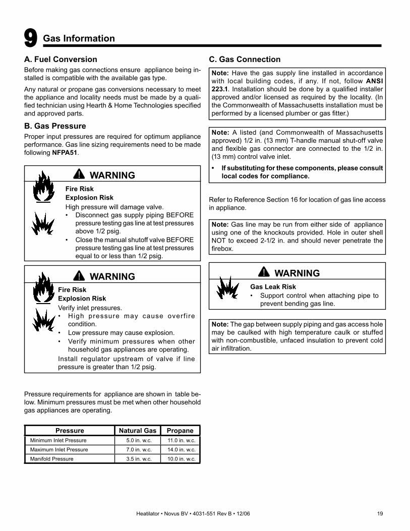
Pressure requirements for appliance are shown in table be-low. Minimum pressures must be met when other household gas appliances are operating.
Pressure Natural Gas PropaneMinimum Inlet Pressure 5.0 in. w.c. 11.0 in. w.c.
Maximum Inlet Pressure 7.0 in. w.c. 14.0 in. w.c.
Manifold Pressure 3.5 in. w.c. 10.0 in. w.c.
WARNINGGas Leak Risk• Support control when attaching pipe to
prevent bending gas line.
Fire RiskExplosion RiskVerify inlet pressures.• High pressure may cause overf i re
condition.• Low pressure may cause explosion.• Verify minimum pressures when other
household gas appliances are operating.Install regulator upstream of valve if line pressure is greater than 1/2 psig.
WARNING
9 9 Gas Information
Fire RiskExplosion RiskHigh pressure will damage valve.• Disconnect gas supply piping BEFORE
pressure testing gas line at test pressures above 1/2 psig.
• Close the manual shutoff valve BEFORE pressure testing gas line at test pressures equal to or less than 1/2 psig.
WARNING
Note: Gas line may be run from either side of appliance using one of the knockouts provided. Hole in outer shell NOT to exceed 2-1/2 in. and should never penetrate the fi rebox.
Note: The gap between supply piping and gas access hole may be caulked with high temperature caulk or stuffed with non-combustible, unfaced insulation to prevent cold air infi ltration.

20 Heatilator • Novus BV • 4031-551 Rev B • 12/06
WARNINGFire RiskExplosion Risk• Gas build-up during line purge may
ignite.• Purge should be performed by qualifi ed
technician.• Ensure adequate ventilation.• Ensure there are no ignition sources such
as sparks or open fl ames.
WARNINGCHECK FOR GAS LEAKSFire RiskExplosion RiskAsphyxiation Risk• Check all fi ttings and connections.• Do not use open fl ame.• After the gas line installation is complete,
all connections must be tightened and checked for leaks with a commercially available, non-corrosive leak check solution. Be sure to rinse off all leak check solution following testing.
Fittings and connections may have loosened during shipping and handling.
D. High Altitude InstallationsU.L. listed gas appliances are tested and approved without requiring changes for elevations from 0 to 2000 ft in the USA and Canada.
When installing this appliance at an elevation above 2000 ft, it may be necessary to decrease the input rating by chang-ing the existing burner orifi ce to a smaller size. Input rate should be reduced by 4% for each 1000 ft above a 2000 ft elevation in the U.S.A., or 10% for elevations between 2000 and 4500 ft in Canada. If the heating value of the gas has been reduced, these rules do not apply. To identify the prop-er orifi ce size, check with the local gas utility.
If installing this appliance at an elevation above 4500 ft (in Canada), check with local authorities.
• Ensure that gas line does not come in contact with outer wrap of appliance. Follow local codes.
• Incoming gas line should be piped into the valve compartment and connected to the 1/2 in. connection on the manual shutoff valve.
• A small amount of air will be in the gas supply lines. When fi rst lighting appliance it will take a short time for air to purge from lines. When purging is complete the appliance will light and operate normally.
WARNINGFire RiskExplosion RiskDo NOT change the valve settings.• This valve has been preset at the
factory.• Changing valve settings may result in fi re
hazard or bodily injury.

Heatilator • Novus BV • 4031-551 Rev B • 12/06 21
A. Recommendation for WireThis appliance requires 110-120 VAC to be wired to the junc-tion box either for use of optional accessories (standing pilot ignition) or for proper operation of the appliance (Intellifi re ignition).
Open the control access panel to view wiring system and gas valve. If this appliance has a red or black ignitor button this appliance has a standing pilot ignition system. If there is no red or black ignitor button, this appliance has an Intellifi re ignition system.
Battery polarity must be correct or module damage will occur.
CAUTIONB. Connecting to the Appliance
Shock RiskExplosion RiskDo NOT wire 110V to valve.Do NOT wire 110V to wall switch• Incorrect wiring will damage millivolt
values.• Incorrect wiring will override IPI safety
lockout and may cause explosion.
WARNING
C. Intellifi re Ignition System WiringThis appliance requires a 110 VAC supply to the appliance junction box for operation. (See Figure 10.1 for a wiring dia-gram and Figure 10.3 for junction box wiring.)
This appliance is equipped with an Intellifi re control valve which operates on a 3 volt system.
This appliance is supplied with a battery pack and a 3 volt AC transformer, which requires the installation of the sup-plied junction box. It is highly recommended that the junction box be installed at this time to avoid reconstruction.
The battery pack requires two D cell batteries (not included). Batteries cannot be placed in the battery pack while using the 3 volt AC transformer. Conversely, the transformer must be unplugged if the battery pack is used.
Optional Accessories RequirementsWiring for optional accessories should be done now to avoid reconstruction.
10 10 Electrical Information
Label all wires prior to disconnection when servicing controls. Wiring errors can cause improper and dangerous operation. Verify proper operation after servicing.
CAUTION
Shock Risk• Replace damaged wire with type 105° C
rated wire.• Wire must have high temperature
insulation.
CAUTION
• This appliance may be used with a wall switch, wall mounted thermostat and/or a remote control.
• If using thermostat use one compatible with a millivolt gas valve system.
• Follow parameters for locating thermostat (see individual thermostat instructions) to ensure proper operation of appliance.
• Use low resistance thermostat wire for wiring from ignition system to the wall switch and thermostat.
• Keep wire lengths short as possible by removing any excess wire length.
• Low voltage and 110 VAC voltage cannot be shared within the same wall box.
Note: This appliance must be electrically wired and grounded in accordance with local codes or, in the absence of local codes, with National Electric Code ANSI/NFPA 70-latest edition or the Canadian Electric Code CSA C22.1.

22 Heatilator • Novus BV • 4031-551 Rev B • 12/06
D. Standing Pilot Ignition System Wiring• This standing pilot ignition system wiring does not require
a 110 VAC supply to operate.
Ignitor FlameSensor
Pilot Assembly
GRN
ORG
BLK
ORG
ControlBoxTo
JunctionBox
BatteryPack
3VAdaptor
BLK
BRNRED
RED
BLKBLU
Valve
LimitSwitch
WHT
+- +
-Wall Switch
WHT
GRN*
Figure 10.1 Intellifi re Pilot Ignition (IPI) Wiring Diagram
PilotIgnitor
GASVALVE
To Burner
Gas Inlet
Inlet Tap
ORG
TAN
Thermopile
WHT RED
Flame Sensor
CopperTubing
PushButtonIgnitor
Outlet Tap
Wall Switch (or thermostat if heater-listed)
WHT
REDGRN wire only used withoptional wall switchWSK-MLT-HTL
HIGHLIMITSWITCH
BLU
BLU
BLK
BLK
Pilot Tube WHT
Figure 10.2 Standing Pilot Ignition Wiring Diagram
• It is recommended that a 110 VAC junction box be installed for use with a fan or remote control. (See Figure 10.2 for a wiring diagram and Figure 10.3 for junction box wiring.)

Heatilator • Novus BV • 4031-551 Rev B • 12/06 23
E. Junction Box InstallationIf the box is being wired from the OUTSIDE of the appli-ance:
• Remove the cover plate located on the outer shell - right side (see Figure 10.3).
• Install the supplied Romex™ connector in the cover plate.
• Feed the necessary length of wire through the connector.
• Make all necessary wire connections and reattach the cover plate to the outer shell.
If the box is being wired from the INSIDE of the appliance:
• Remove the screw attaching the junction box/receptacle to the outer shell, rotate the junction box inward to disengage it from the outer shell (see Figure 10.3).
• Pull the electrical wires from outside the appliance through this opening into the valve compartment.
• Feed the necessary length of wire through the connector.
• Make all necessary wire connections to the junction box/receptacle and reassemble the junction box/receptacle to the outer shell.
WH
T
WHT
BLK
BLK
GRN wireinside box
Copperground attachedto GRN screw withGRN wire
14/2WG
Cover Plateoutside firebox
RomexConnector
Figure 10.3 Junction Box Detail
Note: Do NOT wire 110 VAC to wall switch.
Red
Switch
Switch Box
RedBlackBlack
Green GreenWhite
PowerSupplyWires
White
Red
Bla
ck
Gre
enW
hite
Minimum 14-3 AWGwith Ground
Junction Box
Knockout
Figure 10.4 Fan Control Switch Wiring
F. Wall Switch Installation for Fan (Op-tional)If the box is being wired to a wall mounted switch for use with a fan (See Figure 10.4):
• The power supply for the appliance must be brought into a switch box.
• The power can then be supplied from the switch box to the appliance using a minimum of 14-3 with ground wire.
• At the switch box connect the black (hot) wire and red (switch leg) wire to the wall switch as shown.
• At the appliance connect the black (hot), white (neutral) and green (ground) wires to the junction box as shown.
• Add a 1/4 in. insulated female connector to the red (switch leg) wire, route it through the knockout in the face of the junction box, and connect to the top fan switch connector (1/4 in. male) as shown.

24 Heatilator • Novus BV • 4031-551 Rev B • 12/06
Fire RiskDo NOT obstruct air inlet or outlet grilles.Do NOT modify grilles.• Modifying or covering grilles could cause
temperature rise and fi re hazard.Finishing materials must not interfere with:• Air fl ow through grilles or louvers.• Operation of louvers or doors.• Access for service.
WARNING
A. Mantel ProjectionsFigure 11.1 shows the minimum vertical and corresponding maximum horizontal dimensions of appliance mantels or other combustible projections above the top front edge of the appliance.
B. Facing Material
Measured from top of hood (in inches)
34
56
78
910
1112
1314
1516
1718
55-1/2
6-1/47
7-3/48-1/2
9-1/410
10-3/411-1/2
12-1/413
13-3/414-1/2
15-1/416
32-1/2 in. minimumto ceiling
Figure 11.1 Clearances to Mantels or other Combustibles above Appliance.
1 in. (25 mm) min.to perpendicular wall
A
3-1/2 in. (89 mm) min.from fireplace openingto perpendicular wall
B
48 in.(1219 mm)
max.
Mantel Leg or Perpendicular Wall
Top ofAppliance
Drywall
A
B
Figure 11.2 Mantel Leg or Wall Projections (Acceptable on both sides of opening)
0 in. 0 in.
0 in.
Finish wall material may be combustible - Top and Sides
High Temperature Sealant (300° F/149° C min.)Top and Side Seal Joint
Figure 11.3 Noncombustible Facing Diagram
11 11 Finishing
Fire RiskFinish all edges and fronts to clearances and specifi cations listed in manual.
WARNING
• Metal appliance front may be covered with non-combustible material only.
• Do NOT overlap combustible materials onto appliance front.
• Install combustible materials only up to specifi ed clearances on top, front and sides.
• Seal joints between the fi nished wall and appliance top and sides using only a 300° F minimum sealant.

Heatilator • Novus BV • 4031-551 Rev B • 12/06 25
A. Remove the Shipping MaterialsRemove shipping materials from inside or underneath the fi rebox.
Shock RiskFire RiskUse ONLY optional accessories approved for this appliance.• Using non-listed accessories voids
warranty.• Using non-listed accessories may result
in a safety hazard.• Only Hearth & Home Technologies
approved accessories may be used safely.
WARNING
D. Install the RefractoryInstall as directed in instructions included with refractory.
Explosion Risk• Follow rockwool placement instructions
in this manual.• Do NOT place rockwool directly over
burner ports.• Replace rockwool material annually.Improperly placed rockwool interferes with proper burner operation.
WARNING
Lava Rock &Vermiculite
Rockwool
Figure 12.1 Placement of Rockwool, Lava Rock and Vermiculite
12 12 Appliance Setup
B. Clean the ApplianceClean/vacuum any sawdust that may have accumulated in-side the fi rebox or underneath in the control cavity.
C. AccessoriesInstall approved accessories per instructions included with accessories. Refer to Section 16.
To open the glass, see Section 12.G.
F. FirescreenRemoving Firescreen• Open lower access panel and pull base of screen towards
you.• The top of the screen will slide out of the screen retainers
at the top of the fi rebox opening.Replacing Firescreen• Remove top grille assembly by lifting upwards and pulling
towards you.• Slide top of screen panel into top screen brackets and
rotate bottom of screen to lower door latches.• Close lower access panel and reinstall top grille.
E. Lava Rock, Vermiculite, Rockwool PlacementSee Figure 12.1 for placement location.
Placing the RockwoolRockwool is shipped with this gas appliance. To place the rockwool:
• Place a small amount of 1/2 in. diameter pieces (dime-size) of rockwool on the burner pan so that the rockwool touches but does not cover the holes in the burner pan. This will provide the “glowing embers” look. It is not necessary to use the entire bag. Save the remaining rockwool for future use.
Placing the Lava Rock• See Figure 12.1Placing the Vermiculite• Sprinkle on top of lava rock.

26 Heatilator • Novus BV • 4031-551 Rev B • 12/06
Latches(both bottom
and top)
Glass Assembly
Figure 12.2 Glass Assembly
Handle glass with care.• Inspect the gasket to ensure it is
undamaged.• Inspect the glass for cracks, chips or
scratches.• Do NOT strike, slam or scratch glass.• Do NOT operate appliance with glass
assembly removed, cracked, broken or scratched.
• Replace glass assembly as a complete assembly.
WARNING
I. HoodThe hood is to be located above the glass panel. The hood must be attached or a fi re hazard may result. Locate the four screws just inside the upper section of the appliance. Posi-tion the hood and slide into position. Tighten the four screws. See Figure 12.3.
Figure 12.3 Installing the Hood
H. Grilles and Trim• Install optional marble and brass trim surround kits using
the installation instructions included with them.• Marble, brass, brick, tile or other non-combustible
materials can be used to cover the gap between sheet rock and appliance.
• Do not obstruct or modify the air inlet/outlet grilles.• Leave space to lower the bottom grille and remove the
trim door.
G. Glass Assembly
Removing Glass Assembly• Remove fi rescreen.• Pull the four (30/33/36 in. appliances) or seven (42 in.
appliance) glass assembly latches out of the groove on the glass frame.
• Remove the glass panel from the appliance.Replacing Glass Assembly• Set the glass panel on the lower two or four glass assembly
latches, ensuring the glass panel is centered in the opening.
• Pull out and latch all four or seven glass assembly latches into the groove on the glass frame.
• Replace fi rescreen.
Heatilator • Novus BV • 4031-551 Rev B • 12/06 27
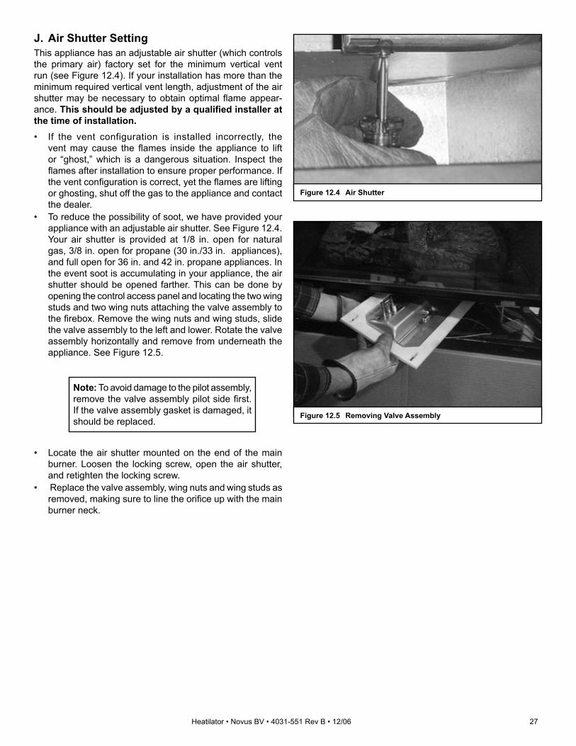
J. Air Shutter SettingThis appliance has an adjustable air shutter (which controls the primary air) factory set for the minimum vertical vent run (see Figure 12.4). If your installation has more than the minimum required vertical vent length, adjustment of the air shutter may be necessary to obtain optimal fl ame appear-ance. This should be adjusted by a qualifi ed installer at the time of installation.• If the vent configuration is installed incorrectly, the
vent may cause the fl ames inside the appliance to lift or “ghost,” which is a dangerous situation. Inspect the fl ames after installation to ensure proper performance. If the vent confi guration is correct, yet the fl ames are lifting or ghosting, shut off the gas to the appliance and contact the dealer.
• To reduce the possibility of soot, we have provided your appliance with an adjustable air shutter. See Figure 12.4. Your air shutter is provided at 1/8 in. open for natural gas, 3/8 in. open for propane (30 in./33 in. appliances), and full open for 36 in. and 42 in. propane appliances. In the event soot is accumulating in your appliance, the air shutter should be opened farther. This can be done by opening the control access panel and locating the two wing studs and two wing nuts attaching the valve assembly to the fi rebox. Remove the wing nuts and wing studs, slide the valve assembly to the left and lower. Rotate the valve assembly horizontally and remove from underneath the appliance. See Figure 12.5.
Figure 12.4 Air Shutter
Figure 12.5 Removing Valve Assembly
Note: To avoid damage to the pilot assembly, remove the valve assembly pilot side fi rst. If the valve assembly gasket is damaged, it should be replaced.
• Locate the air shutter mounted on the end of the main burner. Loosen the locking screw, open the air shutter, and retighten the locking screw.
• Replace the valve assembly, wing nuts and wing studs as removed, making sure to line the orifi ce up with the main burner neck.

28 Heatilator • Novus BV • 4031-551 Rev B • 12/06
A. Before Lighting ApplianceBefore lighting this appliance, determine if it has a stand-ing pilot or Intellifi re ignition system by opening the control access panel to view wiring system and gas valve. If this appliance has a red or black ignitor button (See Figure 10.1) this appliance has a standing pilot ignition system. If there is no red or black ignitor button, this appliance has an Intellifi re ignition system.
If installing Intellifi re Ignition battery backup:• Do not install batteries if the backup mode may
not be used for extended time.• Batteries may leak.• Install batteries only when needed for power
outage.
CAUTION
Fire RiskCombustion Fumes RiskGlass door MUST be in place when appliance is operating. Do NOT operate appliance with glass door removed.• Open viewing glass for servicing only.• Glass door MUST be in place and sealed
before operating appliance.• Only use glass doors certifi ed for use with
the appliance.• Glass replacement should be done by
qualifi ed technician.
WARNING
Fire RiskBurn RiskHOT! DO NOT TOUCH.SEVERE BURNS MAY RESULT.CLOTHING IGNITION MAY RESULTGlass and other surfaces are hot during operation and cool down.
WARNING
• Keep children away.• CAREFULLY SUPERVISE children in same room as
appliance.• Alert children and adults to hazards of high
temperatures.• Do NOT operate with protective barriers open or
removed.• Keep clothing, furniture, draperies and other
combustibles away.This appliance has been supplied with an integral barrier to prevent direct contact with the fixed glass panel. Do NOT operate the appliance with the protective barrier removed.Contact your dealer or Hearth & Home Technologies if the barrier is not present or help is needed to properly install one.
Improper installation, adjustment, alteration, service or maintenance can cause injury or property damage. Refer to the owner’s information manual provided with this appliance. For assistance or additional information consult a qualifi ed installer, service agency or the gas supplier.
WARNING
Do NOT use this appliance if any part has been under water. Immediately call a qualifi ed service technician to inspect the appliance and to replace any part of the control system and any gas control which has been under water.
WARNING
Before operating this appliance, have a qualifi ed technician:• Remove all shipping materials from inside and/or
underneath the fi rebox.• Review proper placement of logs, rockwool, lava rock and
vermiculite.• Check the wiring.• Check the air shutter adjustment.• Ensure that there are no gas leaks.• Ensure that the glass is sealed and in the proper
position.• Ensure that the fl ow of combustion and ventilation air is
not obstructed (front grilles and vent caps).
13 13 Operating Instructions

Heatilator • Novus BV • 4031-551 Rev B • 12/06 29
B. Check Appliance DraftCheck draft of appliance to verify proper venting conditions.
• Close all windows and doors, turn on all exhaust fans in home.
• Appliance is to be completely assembled to normal operating condition.
• Turn on appliance and allow to operate for at least 10 minutes.
• Check draft as shown in Figure 13.1. This can be done using a smoke or fl ame producing match.
• Hold lit match at bottom edge of draft hood opening and observe fl ame/smoke per the fi gure.
Without�doors.
With doors�closed.
Flame up-Acceptable
Flame in-Good
Flame out-Bad
Flame up-Acceptable
Flame in-Good
Flame out-Bad
Figure 13.1 Checking Appliance Draft
30 Heatilator • Novus BV • 4031-551 Rev B • 12/06
C. Lighting the Appliance
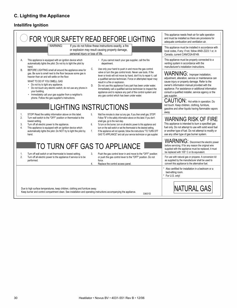
Intellifi re Ignition
A. This appliance is equipped with an ignition device which automatically lights the pilot. Do not try to light the pilot by hand.
B. BEFORE LIGHTING smell all around the appliance area for gas. Be sure to smell next to the floor because some gas is heavier than air and will settle on the floor.
WHAT TO DO IF YOU SMELL GAS • Do not try to light any appliance. • Do not touch any electric switch; do not use any phone in
your building. • Immediately call your gas supplier from a neighbor's
phone. Follow the gas supplier's instructions.
• If you cannot reach your gas supplier, call the fire department.
LIGHTING INSTRUCTIONS1. STOP! Read the safety information above on this label.2. Turn wall switch to the "OFF" position or thermostat to the
lowest setting.3. Turn off all electric power to the appliance.4. This appliance is equipped with an ignition device which
automatically lights the pilot. Do NOT try to light the pilot by hand.
5. Wait five minutes to clear out any gas. If you then smell gas, STOP! Follow "B" in the safety information above on this label. If you don't smell gas, go to the next step.
6. To turn on the burner, turn on all electric power to this appliance and turn on the wall switch or set the thermostat to the desired setting.
7. If the appliance will not operate, follow the instructions "TO TURN OFF GAS TO APPLIANCE" and call your service technician or gas supplier.
TO TURN OFF GAS TO APPLIANCE1. Turn off wall switch or set thermostat to lowest setting.2. Turn off all electric power to the appliance if service is to be
performed.
3. Push the gas control lever in and move to the "OFF" position or push the gas control lever to the "OFF" position. Do not force.
4. Replace the control access panel.
Due to high surface temperatures, keep children, clothing and furniture away.Keep burner and control compartment clean. See installation and operating instructions accompanying the appliance.
WARNING: If you do not follow these instructions exactly, a fire or explosion may result causing property damage, personal injury or loss of life.
FOR YOUR SAFETY READ BEFORE LIGHTING
33631D
C. Use only your hand to push in and move the gas control valve or turn the gas control knob. Never use tools. If the lever or knob will not move by hand, don't try to repair it, call a qualified service technician. Force or attempted repair may result in a fire or explosion.
D. Do not use this appliance if any part has been under water. Immediately call a qualified service technician to inspect the appliance and to replace any part of the control system and any gas control which has been under water.
This appliance needs fresh air for safe operation and must be installed so there are provisions for adequate combustion and ventilation air.
This appliance must be installed in accordance with local codes, if any; if not, follow ANSI Z223.1 or, in Canada, current CAN/CGA-B149.
WARNING: Improper installation, adjustment, alteration, service or maintenance can cause injury or property damage. Refer to the owner's information manual provided with the appliance. For assistance or additional information consult a qualified installer, service agency or the gas supplier.
CAUTION: Hot while in operation. Do not touch. Keep children, clothing, furniture, gasoline and other liquids having flammable vapors away.
WARNING RISK OF FIREThis appliance is intended to burn a specified gas fuel only. Do not attempt to use with solid wood fuel or another type of fuel. Do not attempt to modify or use any other type of gas burner system.
* Also certified for installation in a bedroom or a bed-sitting room.
* For U.S. only!
WARNING: Disconnect the electric power before servicing. If for any reason the original wire supplied with the appliance must be replaced, it must be replaced with 105° C or its equivalent.
For use with natural gas or propane. A conversion kit as supplied by the manufacturer shall be used to convert this appliance to the alternative fuel.
This appliance must be properly connected to a venting system in accordance with the manufacturer's installation instructions.
NATURAL GAS

Heatilator • Novus BV • 4031-551 Rev B • 12/06 31
Standing Pilot Ignition
A.
This
app
lianc
e ha
s a
pilo
t whi
ch m
ust b
e lig
hted
by
hand
. Whe
n lig
htin
g th
e pi
lot,
follo
w th
ese
inst
ruct
ions
exa
ctly.
B.
BE
FOR
E L
IGH
TIN
G s
mel
l all
arou
nd th
e ap
plia
nce
area
for g
as.
Be
sure
to s
mel
l nex
t to
the
floor
bec
ause
som
e ga
s is
hea
vier
th
an a
ir an
d w
ill s
ettle
on
the
floor
.
WH
AT T
O D
O IF
YO
U S
ME
LL G
AS
•
Do
not t
ry to
ligh
t any
app
lianc
e.
• D
o no
t tou
ch a
ny e
lect
ric s
witc
h; d
o no
t use
any
pho
ne in
you
r bu
ildin
g.
• Im
med
iate
ly c
all y
our g
as s
uppl
ier f
rom
a n
eigh
bor's
pho
ne.
Follo
w th
e ga
s su
pplie
r's in
stru
ctio
ns.
•
If yo
u ca
nnot
reac
h yo
ur g
as s
uppl
ier,
call
the
fire
depa
rtmen
t.
LIG
HTI
NG
INS
TRU
CTI
ON
S1.
Tu
rn w
all s
witc
h to
the
"OFF
" pos
ition
or t
herm
osta
t to
the
low
est s
ettin
g.2.
R
emov
e co
ntro
l acc
ess
pane
l.3.
Tu
rn m
anua
l gas
val
ve to
CLO
SE
D. W
ait f
ive
[5] m
inut
es to
cl
ear o
ut a
ny g
as. I
f you
then
sm
ell g
as, S
TOP
! Fol
low
"B" i
n th
e sa
fety
info
rmat
ion
abov
e on
this
labe
l. If
you
don'
t sm
ell g
as, g
o to
nex
t ste
p.4.
Tu
rn g
as li
ne to
"OP
EN
".5.
Tu
rn p
ilot k
nob
cloc
kwis
e
t
o "O
FF".
(Kno
b m
ay h
ave
to b
e de
pres
sed
to p
ass
"PIL
OT"
pos
ition
.)6.
Lo
cate
pilo
t ass
embl
y in
side
app
lianc
e.7.
Lo
cate
red
igni
tor b
utto
n.8.
Tu
rn p
ilot k
nob
to "P
ILO
T" a
nd p
ush
in.
9.
Con
tinue
to h
old
in p
ilot k
nob
and
push
the
red
igni
tor b
utto
n 12
-15
times
unt
il sm
all b
lue
pilo
t fla
me
appe
ars.
10.
Con
tinue
to h
old
in p
ilot k
nob
for a
ppro
xim
atel
y on
e m
inut
e. P
ilot
shou
ld re
mai
n lit
. If p
ilot g
oes
out,
wai
t 5 m
inut
es a
nd re
peat
S
teps
3-9
.11
. R
elea
se a
nd tu
rn k
nob
coun
terc
lock
wis
e
t
o "O
N".
12.
If ap
plia
nce
will
not
ope
rate
, fol
low
the
inst
ruct
ions
"TO
TU
RN
O
FF G
AS
TO
AP
PLI
AN
CE
" and
cal
l you
r ser
vice
tech
nici
an o
r ga
s su
pplie
r.
TO T
UR
N O
FF G
AS
TO
AP
PLI
AN
CE
1.
Turn
off
wal
l sw
itch
or s
et th
erm
osta
t to
low
est s
ettin
g.2.
R
emov
e co
ntro
l acc
ess
pane
l.3.
Tu
rn m
anua
l gas
val
ve to
"CLO
SE
D p
ositi
on. D
o no
t for
ce.
4.
Rep
lace
con
trol a
cces
s pa
nel.
Due
to h
igh
surfa
ce te
rmpe
ratu
res,
kee
p ch
ildre
n, c
loth
ing
and
furn
iture
aw
ay.
Kee
p bu
rner
and
con
trol c
ompa
rtmen
t cle
an. S
ee in
stal
latio
n an
d op
erat
ing
inst
ruct
ions
acc
ompa
nyin
g th
e ap
plia
nce.
WA
RN
ING
: If
you
do n
ot fo
llow
thes
e in
stru
ctio
ns e
xact
ly, a
fire
or
expl
osio
n m
ay re
sult
caus
ing
prop
erty
dam
age,
per
sona
l in
jury
or l
oss
of li
fe.
FOR
YO
UR
SAF
ETY
REA
D B
EFO
RE
LIG
HTI
NG
2909
7D
This
app
lianc
e ne
eds
fresh
air
for s
afe
oper
atio
n an
d m
ust b
e in
stal
led
so th
ere
are
prov
isio
ns fo
r ad
equa
te c
ombu
stio
n an
d ve
ntila
tion
air.
This
app
lianc
e m
ust b
e in
stal
led
in a
ccor
danc
e w
ith
loca
l cod
es, i
f any
; if n
ot, f
ollo
w A
NS
I Z22
3.1
or, i
n C
anad
a, c
urre
nt C
AN
/CG
A-B
149.
WA
RN
ING
: Im
prop
er in
stal
latio
n,
adju
stm
ent,
alte
ratio
n, s
ervi
ce o
r mai
nten
ance
can
ca
use
inju
ry o
r pro
perty
dam
age.
Ref
er to
the
owne
r's
info
rmat
ion
man
ual p
rovi
ded
with
the
appl
ianc
e. F
or
assi
stan
ce o
r add
ition
al in
form
atio
n co
nsul
t a
qual
ified
inst
alle
r, se
rvic
e ag
ency
or t
he g
as s
uppl
ier.
CA
UTI
ON
: Hot
whi
le in
ope
ratio
n. D
o no
t tou
ch. K
eep
child
ren,
clo
thin
g, fu
rnitu
re,
gaso
line
and
othe
r liq
uids
hav
ing
flam
mab
le v
apor
s aw
ay.
WAR
NIN
G R
ISK
OF
FIR
ETh
is a
pplia
nce
is in
tend
ed to
bur
n a
spec
ified
gas
fu
el o
nly.
Do
not a
ttem
pt to
use
with
sol
id w
ood
fuel
or
ano
ther
type
of f
uel.
Do
not a
ttem
pt to
mod
ify o
r us
e an
y ot
her t
ype
of g
as b
urne
r sys
tem
.
* A
lso
certi
fied
for i
nsta
llatio
n in
a b
edro
om o
r a
bed-
sitti
ng ro
om.
* Fo
r U.S
. onl
y!
C.
Use
onl
y yo
ur h
and
to p
ush
in o
r tur
n kn
ob. N
ever
use
tool
s. If
th
e m
anua
l gas
val
ve w
ill n
ot p
ush
in o
r tur
n by
han
d, d
on't
try
to re
pair
it; c
all a
qua
lifie
d se
rvic
e te
chni
cian
. For
ce o
r at
tem
pted
repa
ir m
ay re
sult
in a
fire
or e
xplo
sion
.D
. D
o no
t use
this
app
lianc
e if
any
part
has
been
und
er w
ater
. Im
med
iate
ly c
all a
qua
lifie
d se
rvic
e te
chni
cian
to in
spec
t the
ap
plia
nce
and
to re
plac
e an
y pa
rt of
the
cont
rol s
yste
m a
nd a
ny
gas
cont
rol w
hich
has
bee
n un
der w
ater
.
Sto
p! R
ead
the
safe
ty in
form
atio
n ab
ove
on th
is la
bel.
ON OFF
PILOT
OFF
PILO
T
ONOFF
PILOT
5
ON
OFF
VENT
ON
7
58
11
3. C
LOS
ED
4. O
PE
N
WA
RN
ING
: Dis
conn
ect t
he e
lect
ric p
ower
be
fore
ser
vici
ng. I
f for
any
reas
on th
e or
igin
al w
ire
supp
lied
with
the
appl
ianc
e m
ust b
e re
plac
ed, i
t mus
t be
repl
aced
with
105
° C
or i
ts e
quiv
alen
t.
For u
se w
ith n
atur
al g
as o
r pro
pane
. A c
onve
rsio
n ki
t as
supp
lied
by th
e m
anuf
actu
rer s
hall
be u
sed
to
conv
ert t
his
appl
ianc
e to
the
alte
rnat
ive
fuel
.
This
app
lianc
e m
ust b
e pr
oper
ly c
onne
cted
to a
ve
ntin
g sy
stem
in a
ccor
danc
e w
ith th
e m
anuf
actu
rer's
inst
alla
tion
inst
ruct
ions
.
NATU
RAL
GAS
NO
TE: T
o lig
ht m
ain
burn
er, t
urn
wal
l sw
itch
to "O
N".
Do
not l
ight
by
hand
.

32 Heatilator • Novus BV • 4031-551 Rev B • 12/06
Note: This appliance should be run three to four hours on the initial start-up. Turn it off and let it cool completely. Remove and clean the glass. Replace the glass and run the appliance for an additional 12 hours. This will help cure the products used in the paint and logs.
• Prevent accidental appliance operation when not attended.
• Unplug or remove batteries from remote control if absent or if appliance will not be used for an extended period of time.
• Property damage possib le f rom elevated temperatures.
CAUTION
Smoke and odors are released during initial operation.• Open windows for air circulation.• Leave room during initial operation.• Smoke may set off smoke detectors.Smoke and odors may be irr i tating to sensit ive individuals.
CAUTION
Fire RiskKeep combustible materials, gasoline and other fl ammable vapors and liquids clear of appliance.• Do NOT store fl ammable materials in the
vicinity of the appliance.• Do NOT use gasoline, lantern fuel,
kerosene, charcoal lighter fl uid or similar liquids in this appliance.
Combustible materials may ignite.
WARNING
Fire RiskHigh TemperaturesKeep combustible household items away from appliance. Do NOT obstruct combustion and ventilation air.• Do NOT place combustible items on top
of or in front of appliance.• Keep furniture, draperies away from
appliance.
WARNING
E. Frequently Asked Questions
D. After the Appliance is LitInitial Break-in ProcedureWhen you light the appliance, you may notice that it pro-duces heat which does have an associated odor or smell. If you feel this odor is excessive it may require the initial three to four hour continuous burn on high followed by a second burn up to 12 hours to fully drive off any odor from paint and lubricants used in the manufacturing process. Condensation of the glass is normal
During this break-in period it is recommended that some windows in the house be opened for air circulation. This will help avoid setting off smoke detectors, and help eliminate any odors associated with the appliance’s initial burning.
Issue SolutionsCondensation on the glass This is a result of gas combustion and temperature variations. As the appliance warms, this condensation will
disappear.
Blue fl ames This is a result of normal operation and the fl ames will begin to yellow as the appliance is allowed to burn for 20 to 40 minutes.
Odor from appliance When fi rst operated, this appliance may release an odor for the fi rst several hours. This is caused by the curing of the paint and the burning off of any oils remaining from manufacturing.
Film on the glass This is a normal result of the curing process of the paint and logs. Glass should be cleaned within 3 to 4 hours of initial burning to remove deposits left by oils from the manufacturing process. A non-abrasive cleaner such as gas fi replace glass cleaner may be necessary. See your dealer.
Metallic noise Noise is caused by metal expanding and contracting as it heats up and cools down, similar to the sound produced by a furnace or heating duct. This noise does not affect the operation or longevity of the fi replace.
Is it normal to see the pilot fl ame burn continually?
In an Intellifi re ignition system it is normal to see the pilot fl ame, but it should turn off when ON/OFF is turned off. In a standing pilot system the pilot will always stay on.

Heatilator • Novus BV • 4031-551 Rev B • 12/06 33
With proper installation, operation and maintenance your gas appliance will provide years of trouble-free service. If you do experience a problem, this troubleshooting guide will assist a qualifi ed service person in the diagnosis of a problem and the corrective action to be taken. This troubleshooting guide can only be used by a qualifi ed service technician.
A. Standing Pilot Ignition System
Symptom Possible Causes Corrective Actions1. After repeated triggering
of the red or black piezo ignitor button, the spark ignitor will not light the pilot.
A. Defective ignitor. Check the spark at the electrode and pilot. If there is no spark and the electrode wire is properly connected, replace the ignitor.
B. Defective pilot or misaligned electrode (spark at electrode).
Using a match, light the pilot. If the pilot lights, turn off the pilot and trigger the red or black piezo ignitor button again. If the pilot lights, an improper gas/air mixture caused the bad lighting and a longer purge period is recommended. If the pilot will not light, ensure the gap at the electrode and pilot is 1/8 in. to have a strong spark. If the gap is OK, replace the pilot.
C. No gas or low gas pressure.
Check the remote shut-off valves from the appliance. There is usually a valve near the gas main. There can be more than one valve between the appliance and the main.
D. No LP in tank. Check the LP (propane) tank. You may be out of fuel.
2. The pilot will not stay lit after carefully following the lighting instructions
A. Defective thermocouple. Check that the pilot fl ame impinges on the thermocouple. Clean and/or adjust the pilot for maximum fl ame impingement.Ensure that the thermocouple connection at the gas valve is fully inserted and tight (hand tighten plus 1/4 turn).Disconnect the thermocouple from the valve, place one millivolt meter lead wire on the tip of the thermocouple and the other meter lead wire on the thermocouple copper lead. Start the pilot and hold the valve knob in. If the millivolt reading is less than 15mV, replace the thermocouple.
B. Defective valve. If the thermocouple is producing more than 15 millivolts, replace faulty valve.
3. The pilot is burning, there is no gas burning, the valve knob is in the ON position, and the ON/OFF switch is in the ON position.
A. ON/OFF switch or wires are defective.
Check the ON/OFF switch and wires for proper connections. Place the jumper wires across the terminals at the switch. If the burner comes on, replace the defective switch. If the switch is OK, place the jumper wires across the switch wires at the gas valve. If the burner comes on, the wires are faulty or connections are bad.
B. Thermopile may not be generating suffi cient millivoltage.
If the pilot fl ame is not close enough physically to the thermopile, adjust the pilot fl ame.Be sure the wire connections from the thermopile at the gas valve terminals are tight and that the thermopile is fully inserted into the pilot bracket.Check the thermopile with a millivolt meter. Take the reading at TH-TP&TP terminals of the gas valve. The meter should read 325 millivolts minimum while holding the valve knob depressed in the pilot position, with the pilot lit, and the ON/OFF switch in the OFF position. Replace the faulty thermopile of the reading is below the specifi ed minimum.With the pilot in the ON position, disconnect the thermopile leads from the valve. Take a reading at the thermopile leads. The reading should be 325 millivolts minimum. Replace the thermopile if the reading is below the minimum.
C. Defective valve. Turn the valve knob to the ON position. Place the ON/OFF switch in the ON position. Check the millivolt meter at the thermopile terminals. The millivolt meter should read greater than 125mV. If the reading is acceptable, and if the burner does not come on, replace the gas valve.
D. Plugged burner orifi ce. Check the burner orifi ce for stoppage. Remove stoppage.
E. Wall switch or wires are defective.
Follow the corrective action in Symptom and Possible Cause 1.A. above. Check the switch and wiring. Replace where defective.
14 14 Troubleshooting

34 Heatilator • Novus BV • 4031-551 Rev B • 12/06
Symptom Possible Causes Corrective Actions4. Frequent pilot outage
problem.A. Pilot fl ame may be too
high, too low, or blowing (high), causing pilot safety to drop out.
Clean and adjust the pilot fl ame for maximum fl ame impingement on thermocouple. Follow lighting instructions carefully.
5. The pilot and main burner extinguish while in operation.
A. No LP in the tank. Check the LP (propane) tank. Refi ll the fuel tank.
B. Inner vent pipe is leaking exhaust gases back into the system.
Check venting system for damage. Replace/repair improperly assembled pipe sections.
C. Glass is too loose and air tight packet leaks in corners after usage.
Replace glass panel assembly.
D. Bad thermopile or thermocouple.
Replace if necessary.
E. Improper vent cap installation.
Check for proper installation and freedom from debris or blockage.
6. Glass soots. A. Flame impingement. Adjust the log set so that the fl ame does not excessively impinge on it.
B. Improper air shutter setting.
Adjust the air shutter located on the control panel.
C. Debris around air shutter. Inspect the opening at the base of the burner. NO MATERIAL SHOULD BE PLACED IN THIS OPENING.
7. Flame burns blue and lifts off burner.
A. Insuffi cient oxygen being supplied.
Ensure that the vent cap is installed properly and free of debris.Ensure that the vent system joints are tight and have no leaks.Ensure that no debris has been placed at the base of, or in the area of the air holes in the center of, the base pan beneath the burner.Ensure that the glass is tightened properly on the appliance, particularly on top corners.

Heatilator • Novus BV • 4031-551 Rev B • 12/06 35
B. Intellifi re Ignition System
Symptom Possible Causes Corrective Actions1. The ignitor/module makes
noise, but no spark.A. Incorrect wiring. Verify “S” wire (white) for sensor and “I” wire (orange) for ignitor are
connected to the correct terminals on the module and the pilot assembly. Reversed wires at the module may cause the system to make a sparking noise, but the spark may not be present at pilot hood.
B. Loose connections or electrical shorts in the wiring.
Verify there are no loose connections or electrical shorts in wiring from module to pilot assembly. The rod closest to the pilot hood should be ignitor. Verify connections underneath pilot assembly are tight; also verify the connections are not grounding out to the metal chassis, pilot burner, pilot enclosure, mesh screen if present, or any other metal object.
C. Ignitor gap is too large. Verify gap of ignitor to pilot hood. The gap should be approximately .17 in. or 1/8 in.
D. Faulty module. Turn ON/OFF rocker switch or wall switch to OFF position. Remove ignitor wire “I” from module. Place ON/OFF rocker switch or wall switch in ON position. Hold ground wire about 3/16 in. away from “I” terminal on module. If there is no spark at “I” terminal, module must be replaced. If there is a spark at “I” terminal, module is fi ne. Inspect pilot assembly for shorted sparker wire or cracked insulator around electrode.
2. Pilots won’t light, there is no noise or spark.
A. Transformer installed incorrectly.
Verify that transformer is installed and plugged into module. Check voltage of transformer under load at space connection on module with ON/OFF switch in ON position. Acceptable readings of a good transformer are between 3.2 and 2.8 volts AC.
B. A shorted or loose connection in wiring confi guration or wiring harness.
Remove and reinstall the wiring harness that plugs into module. Verify there is a tight fi t. Verify pilot assembly wiring to module. Remove and verify continuity of each wire in wiring harness.
C. Improper wall switch wiring.
Verify wall switch is wired correctly.
D. Module not grounded. Verify black ground wire from module wire harness is grounded to metal chassis of appliance.
E. Faulty module. Turn ON/OFF rocker switch or wall switch to OFF position. Remove ignitor wire “I” from module. Place ON/OFF rocker switch or wall switch in ON position. Hold ground wire about 3/16 in. away from “I” terminal on module. If there is no spark at “I” terminal module must be replaced. If there is a spark at “I” terminal, module is fi ne. Inspect pilot assembly for shorted sparker wire or cracked insulator around electrode.
3. Pilot lights but continues to spark, and main burner will not ignite. (If the pilot continues to spark after the pilot fl ame has been lit, fl ame rectifi cation has not occurred.)
A. A shorted or loose connection in sensor rod.
Verify all connections to wiring diagram in manual. Verify connections underneath pilot assembly are tight. Verify connections are not grounding out to metal chassis, pilot burner, pilot enclosure or screen if present, or any other metal object.
B. Poor fl ame rectifi cation or contaminated sensor rod.
Verify fl ame is engulfi ng sensor rod. If the pilot assembly does not have a ground strap, consider installing one to increase fl ame rectifi cation. Verify correct pilot orifi ce is installed and inlet gas specifi cations are met. Flame carries rectifi cation current, not the gas. If fl ame lifts from pilot hood, the circuit is broken. A wrong orifi ce or too high an inlet pressure can cause pilot fl ame to lift. The sensor rod may be contaminated. Clean sensor rod with emery cloth.
C. Module is not grounded. Verify that module is securely grounded to metal chassis of appliance. Verify that the wire harness is fi rmly connected to module.
D. Damaged pilot assembly or dirty sensor rod.
Verify that ceramic insulator around the sensor rod is not cracked, damaged, or loose. Verify connection from sensor rod to white sensor wire. Clean sensor rod with emery cloth to remove any contaminants that may have accumulated on sensor rod. Verify continuity with a multimeter with ohms set at lowest range.
E. Faulty module. Turn ON/OFF rocker switch or wall switch to OFF position. Remove ignitor wire “I” from module. Place ON/OFF rocker switch or wall switch in ON position. Hold ground wire about 3/16 in. away from “I” terminal on module. If there is no spark at “I” terminal, module must be replaced. If there is a spark at “I” terminal, module is fi ne. Inspect pilot assembly for shorted sparker wire or cracked insulator around electrode.

36 Heatilator • Novus BV • 4031-551 Rev B • 12/06
Symptom Possible Causes Corrective Actions4. Pilot sparks, but pilot will
not light.A. Correct gas supply. Verify that incoming gas line ball valve is “open”. Verify that inlet pressure
reading is within acceptable limits, inlet pressure must not exceed 14 in. w.c.
B. Ignitor gap is too large. Verify that spark gap from ignitor to pilot hood is .17 in. or 1/8 in.
C. Module is not grounded. Verify module is securely grounded to metal chassis of appliance.
D. Module voltage output/valve/pilot solenoid ohms readings.
Replace module.
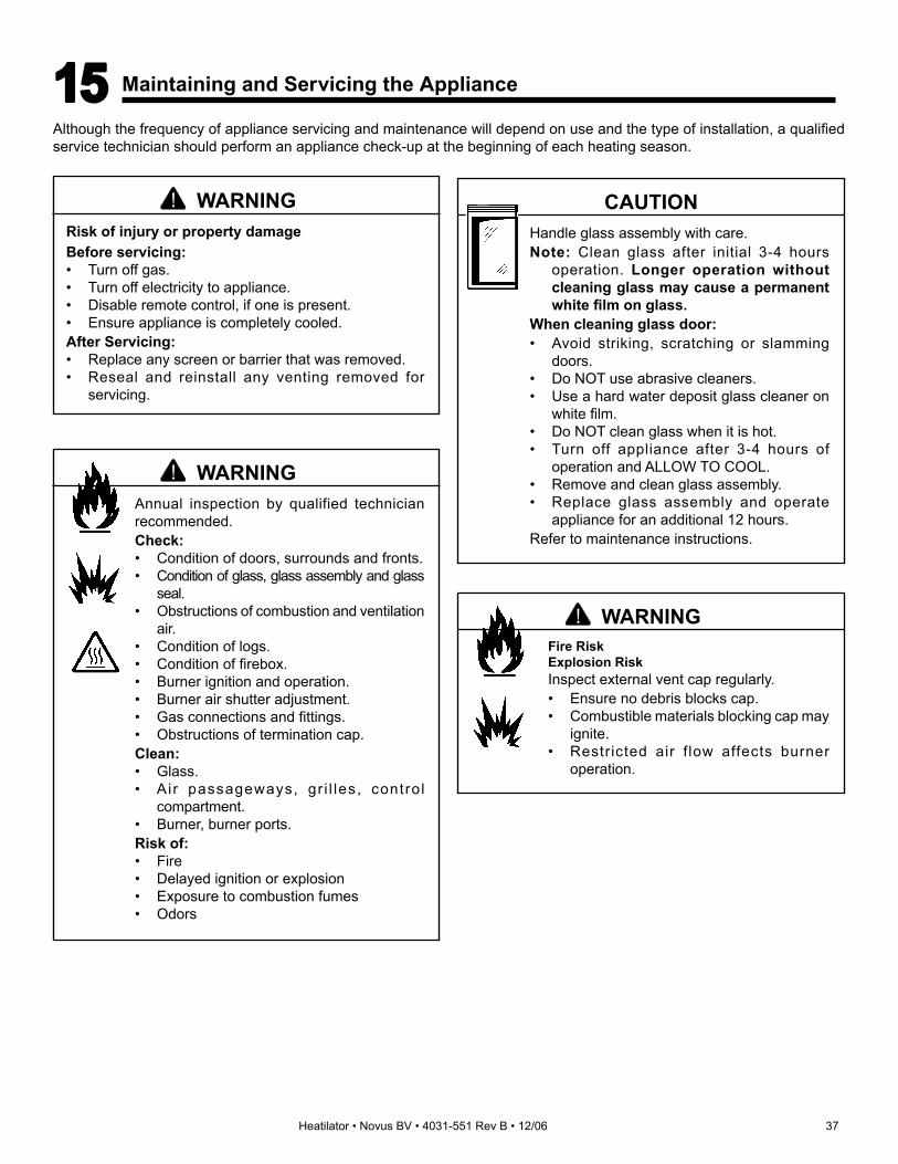
Heatilator • Novus BV • 4031-551 Rev B • 12/06 37
Although the frequency of appliance servicing and maintenance will depend on use and the type of installation, a qualifi ed service technician should perform an appliance check-up at the beginning of each heating season.
Fire RiskExplosion RiskInspect external vent cap regularly.• Ensure no debris blocks cap.• Combustible materials blocking cap may
ignite.• Restricted air f low affects burner
operation.
WARNING
Annual inspection by qualified technician recommended.Check:• Condition of doors, surrounds and fronts.• Condition of glass, glass assembly and glass
seal.• Obstructions of combustion and ventilation
air.• Condition of logs.• Condition of fi rebox.• Burner ignition and operation.• Burner air shutter adjustment.• Gas connections and fi ttings.• Obstructions of termination cap.Clean:• Glass.• Air passageways, gr i l les, control
compartment.• Burner, burner ports.Risk of:• Fire• Delayed ignition or explosion• Exposure to combustion fumes• Odors
WARNING
Handle glass assembly with care.Note: Clean glass after initial 3-4 hours
operation. Longer operation without cleaning glass may cause a permanent white fi lm on glass.
When cleaning glass door:• Avoid striking, scratching or slamming
doors.• Do NOT use abrasive cleaners.• Use a hard water deposit glass cleaner on
white fi lm.• Do NOT clean glass when it is hot.• Turn off appliance after 3-4 hours of
operation and ALLOW TO COOL.• Remove and clean glass assembly.• Replace glass assembly and operate
appliance for an additional 12 hours.Refer to maintenance instructions.
CAUTION
15 15 Maintaining and Servicing the Appliance
Risk of injury or property damageBefore servicing:• Turn off gas.• Turn off electricity to appliance.• Disable remote control, if one is present.• Ensure appliance is completely cooled.After Servicing:• Replace any screen or barrier that was removed.• Reseal and reinstall any venting removed for
servicing.
WARNING

38 Heatilator • Novus BV • 4031-551 Rev B • 12/06
Inspect Maintenance TasksDoors, surrounds and fronts 1. Access condition of screen and replace as necessary. Recommend addition of screen if
one is not present.2. Inspect for scratches, dents or other damage and repair as necessary.
3. Verify no obstructions to airfl ow through the louvers.
4. Verify proper clearance to combustible household objects is maintained.
Gasket seal, glass assembly and glass 1. Inspect gasket seal and its condition.
2. Inspect glass panels for scratches and nicks that can lead to breakage when exposed to heat.
3. Confi rm there is no damage to glass or glass frame. Replace as necessary.
4. Verify that latches engage properly, clip studs are not stripped, and glass attachment components are intact and operating properly. Replace as necessary.
5. Clean glass using a nonabrasive cleaner such as Brasso®. Replace glass assembly if severely coated with silicate deposits that cannot be removed.
Valve compartment and fi rebox top 1. Vacuum and wipe out dust, cobwebs, debris or pet hair. Use caution when cleaning these areas. Screw tips that have penetrated the sheet metal are sharp and should be avoided.
2. Remove any foreign objects.
3. Verify unobstructed air circulation.
Logs 1. Inspect for broken, damaged, or missing logs. Replace as necessary.
2. Verify correct log placement and no fl ame impingement causing sooting. Correct as necessary.
Firebox 1. Inspect for paint condition, warpage, corrosion or perforation. Sand and repaint as necessary.
2. Replace appliance if fi rebox has been perforated.
Burner ignition and operation 1. Verify burner is properly secured and aligned with pilot or ignitor.
2. Clean off burner top, inspect for plugged ports, corrosion or deterioration. Replace burner if necessary.
3. Replace rockwool with new dime-sized and shaped pieces. Do not block ports or obstruct lighting paths.
4. Check for smooth lighting and ignition carryover to all ports. Verify there is no ignition delay.
5. Inspect for lifting or other fl ame problems.
6. Verify air shutter is clear of dust and debris.
7. Inspect orifi ce for soot, dirt or corrosion.
8. Verify manifold and inlet pressures. Adjust regulator as required.
9. Inspect pilot fl ame strength. Clean or replace orifi ce as necessary.
10. Inspect thermocouple/thermopile or IPI sensor rod for soot, corrosion and deterioration. Clean with emery cloth or replace as required.
11. Verify millivolt output. Replace as necessary.
Venting 1. Inspect venting for blockage or obstruction such as birds’ nests, leaves, etc.
2. Confi rm that termination cap remains clear and unobstructed by plants, etc.
3. Verify that termination cap clearance to subsequent construction (building additions, decks, fences or sheds) has been maintained.
4. Inspect for corrosion or separation.
5. Verify weather stripping sealing and fl ashing remain intact.
6. Inspect draft shield to verify it is not bent, damaged or missing.
Remote controls 1. Verify operation of remote.
2. Replace batteries in remote transmitters and battery-powered receivers.
3. Verify batteries have been removed from battery back-up in IPI systems to prevent premature battery failure or leaking.
Maintenance and Service Tasks:

Heatilator • Novus BV • 4031-551 Rev B • 12/06 39
A. Appliance Dimension DiagramDimensions are actual appliance dimensions. Use for reference only. For framing dimensions and clearances refer to Sec-tion 3.
Figure 16.1 Appliance Dimensions
16 16 Reference Materials
Model A B CNB3630 inches 35 30 8-5/8
mm 889 762 219
NB3933 inches 38 33 11-5/8
mm 965 838 295
NB4236 inches 41 36 14-5/8
mm 1041 914 371
NB4842 inches 47 42 20-5/8
mm 1194 1067 524
A
B
31-1/2 in.(800 mm)
1-1/2 in.(38 mm)
19-1/8 in.(486 mm)
11-5/8 in.(295 mm)
C
3 in(76 mm).
6-1/2 in.(165 mm)
2-3/8 in.(60 mm)
13-1/4 in.(337 mm)
8 in.(203 mm)
2 in.(51 mm)
34-1/2 in.(876 mm)
Gas LineAccess
Gas LineAccess
ElectricalAccess
34 in.(864 mm)

40 Heatilator • Novus BV • 4031-551 Rev B • 12/06
B. Service Parts List
Exploded Parts DiagramNB3630
Service Parts NOVUS/NB CIR BVBeginning Manufacturing Date: 4/7/03
Ending Manufacturing Date: Active
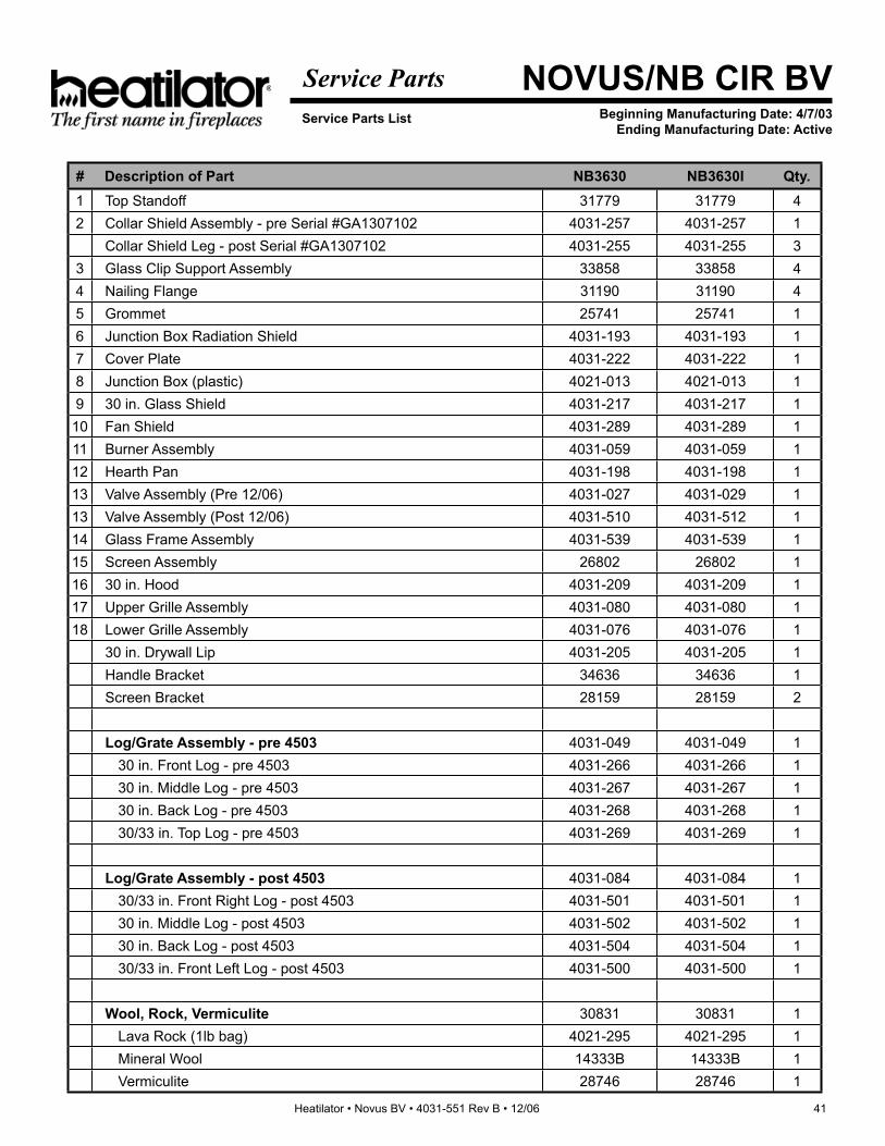
Heatilator • Novus BV • 4031-551 Rev B • 12/06 41
Service Parts List
Service Parts NOVUS/NB CIR BVBeginning Manufacturing Date: 4/7/03
Ending Manufacturing Date: Active
# Description of Part NB3630 NB3630I Qty.1 Top Standoff 31779 31779 42 Collar Shield Assembly - pre Serial #GA1307102 4031-257 4031-257 1
Collar Shield Leg - post Serial #GA1307102 4031-255 4031-255 33 Glass Clip Support Assembly 33858 33858 44 Nailing Flange 31190 31190 45 Grommet 25741 25741 16 Junction Box Radiation Shield 4031-193 4031-193 17 Cover Plate 4031-222 4031-222 18 Junction Box (plastic) 4021-013 4021-013 19 30 in. Glass Shield 4031-217 4031-217 1
10 Fan Shield 4031-289 4031-289 111 Burner Assembly 4031-059 4031-059 112 Hearth Pan 4031-198 4031-198 113 Valve Assembly (Pre 12/06) 4031-027 4031-029 113 Valve Assembly (Post 12/06) 4031-510 4031-512 114 Glass Frame Assembly 4031-539 4031-539 115 Screen Assembly 26802 26802 116 30 in. Hood 4031-209 4031-209 117 Upper Grille Assembly 4031-080 4031-080 118 Lower Grille Assembly 4031-076 4031-076 1
30 in. Drywall Lip 4031-205 4031-205 1Handle Bracket 34636 34636 1Screen Bracket 28159 28159 2
Log/Grate Assembly - pre 4503 4031-049 4031-049 130 in. Front Log - pre 4503 4031-266 4031-266 130 in. Middle Log - pre 4503 4031-267 4031-267 130 in. Back Log - pre 4503 4031-268 4031-268 130/33 in. Top Log - pre 4503 4031-269 4031-269 1
Log/Grate Assembly - post 4503 4031-084 4031-084 130/33 in. Front Right Log - post 4503 4031-501 4031-501 130 in. Middle Log - post 4503 4031-502 4031-502 130 in. Back Log - post 4503 4031-504 4031-504 130/33 in. Front Left Log - post 4503 4031-500 4031-500 1
Wool, Rock, Vermiculite 30831 30831 1Lava Rock (1lb bag) 4021-295 4021-295 1Mineral Wool 14333B 14333B 1Vermiculite 28746 28746 1

42 Heatilator • Novus BV • 4031-551 Rev B • 12/06
Exploded Parts DiagramNB3630
Service Parts NOVUS/NB CIR BVBeginning Manufacturing Date: 4/7/03
Ending Manufacturing Date: Active
#13 SP VALVE ASSEMBLY
1
2
3
4
5
6
7
8
9
10
11 12
13
17
#13 IPI VALVE ASSEMBLY
1
2
3
4
56
7
8
9
10
1112
14
15
16
17
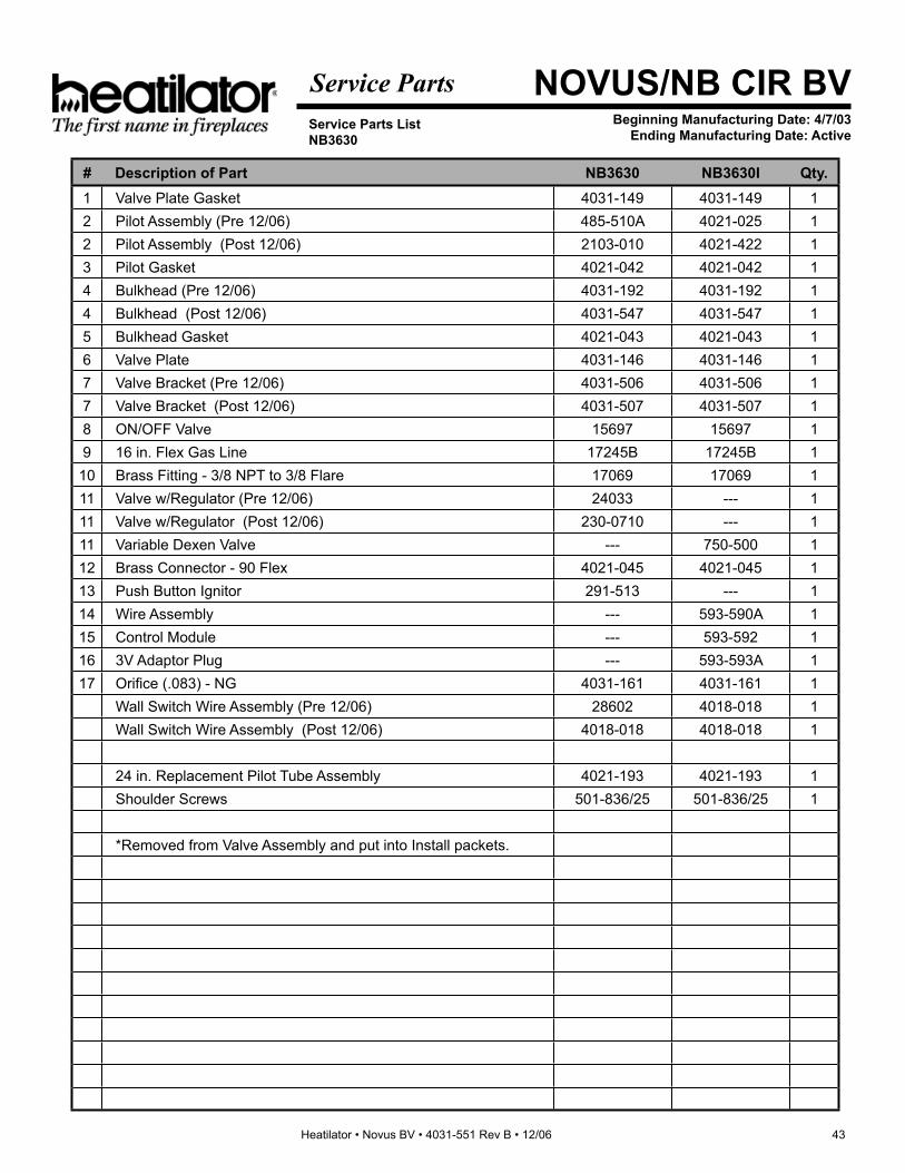
Heatilator • Novus BV • 4031-551 Rev B • 12/06 43
Service Parts ListNB3630
Service Parts NOVUS/NB CIR BVBeginning Manufacturing Date: 4/7/03
Ending Manufacturing Date: Active
# Description of Part NB3630 NB3630I Qty.1 Valve Plate Gasket 4031-149 4031-149 12 Pilot Assembly (Pre 12/06) 485-510A 4021-025 12 Pilot Assembly (Post 12/06) 2103-010 4021-422 13 Pilot Gasket 4021-042 4021-042 14 Bulkhead (Pre 12/06) 4031-192 4031-192 14 Bulkhead (Post 12/06) 4031-547 4031-547 15 Bulkhead Gasket 4021-043 4021-043 16 Valve Plate 4031-146 4031-146 17 Valve Bracket (Pre 12/06) 4031-506 4031-506 17 Valve Bracket (Post 12/06) 4031-507 4031-507 18 ON/OFF Valve 15697 15697 19 16 in. Flex Gas Line 17245B 17245B 1
10 Brass Fitting - 3/8 NPT to 3/8 Flare 17069 17069 111 Valve w/Regulator (Pre 12/06) 24033 --- 111 Valve w/Regulator (Post 12/06) 230-0710 --- 111 Variable Dexen Valve --- 750-500 112 Brass Connector - 90 Flex 4021-045 4021-045 113 Push Button Ignitor 291-513 --- 114 Wire Assembly --- 593-590A 115 Control Module --- 593-592 116 3V Adaptor Plug --- 593-593A 117 Orifi ce (.083) - NG 4031-161 4031-161 1
Wall Switch Wire Assembly (Pre 12/06) 28602 4018-018 1Wall Switch Wire Assembly (Post 12/06) 4018-018 4018-018 1
24 in. Replacement Pilot Tube Assembly 4021-193 4021-193 1Shoulder Screws 501-836/25 501-836/25 1
*Removed from Valve Assembly and put into Install packets.

44 Heatilator • Novus BV • 4031-551 Rev B • 12/06
Exploded Parts DiagramNB3933
Service Parts NOVUS/NB CIR BVBeginning Manufacturing Date: 4/7/03
Ending Manufacturing Date: Active

Heatilator • Novus BV • 4031-551 Rev B • 12/06 45
Service Parts ListNB3933
Service Parts NOVUS/NB CIR BVBeginning Manufacturing Date: 4/7/03
Ending Manufacturing Date: Active
# Description of Part NB3933 NB3933I Qty.1 Top Standoff 31779 31779 42 Collar Shield Assembly - pre Serial #GA1307102 4031-257 4031-257 1
Collar Shield Leg - post Serial #GA1307102 4031-255 4031-255 33 Glass Clip Support Assembly 33858 33858 44 Nailing Flange 31190 31190 45 Grommet 25741 25741 16 Junction Box Radiation Shield 4031-193 4031-193 17 Cover Plate 4031-222 4031-222 18 Junction Box (Plastic) 4021-013 4021-013 19 33 in. Glass Shield 4021-218 4021-218 1
10 Fan Shield 4031-290 4031-290 111 Burner Assembly 4031-061 4031-061 112 Hearth Pan 4031-199 4031-199 113 Valve Assy (Pre 12/06) 4031-027 4031-029 113 Valve Assy (Post 12/06) 4031-510 4031-512 114 Glass Frame Assembly 4031-540 4031-540 115 Screen Assembly 26803 26803 116 33 in. Hood 4031-210 4031-210 117 Upper Grille Assembly 4031-081 4031-081 118 Lower Grille Assembly 4031-077 4031-077 1
33 in. Drywall Lip 4031-206 4031-206 1Handle Bracket 34636 34636 1Screen Bracket 28159 28159 2
Log/Grate Assembly - pre 4503 4031-050 4031-050 130/33 in. Top Log - pre 4503 4031-269 4031-269 133 in. Front Log - pre 4503 4031-270 4031-270 133 in. Middle Log - pre 4503 4031-271 4031-271 133 in. Back Log - pre 4503 4031-272 4031-272 1
Log/Grate Assembly - post 4503 4031-085 4031-085 130/33 in. Front Right Log - post 4503 4031-501 4031-501 130/33 in. Front Left Log - post 4503 4031-500 4031-500 133 in. Middle Log - post 4503 4031-503 4031-503 133 in. Back Log - post 4503 4031-505 4031-505 1
Wool, Rock, Vermiculite 30831 30831 1Lava Rock (1lb Bag) 4021-295 4021-295 1Mineral Wool 14333B 14333B 1Vermiculite 28746 28746 1

46 Heatilator • Novus BV • 4031-551 Rev B • 12/06
Exploded Parts DiagramNB3933
Service Parts NOVUS/NB CIR BVBeginning Manufacturing Date: 4/7/03
Ending Manufacturing Date: Active
#13 SP VALVE ASSEMBLY
1
2
3
4
5
6
7
8
9
10
11 12
13
17
#13 IPI VALVE ASSEMBLY
1
2
3
4
56
7
8
9
10
1112
14
15
16
17

Heatilator • Novus BV • 4031-551 Rev B • 12/06 47
Service Parts ListNB3933
Service Parts NOVUS/NB CIR BVBeginning Manufacturing Date: 4/7/03
Ending Manufacturing Date: Active
# Description of Part NB3933 NB3933I Qty.1 Valve Plate Gasket 4031-149 4031-149 12 Pilot Assembly (Pre 12/06) 485-510A 4021-025 12 Pilot Assembly (Post 12/06) 2103-010 4021-422 13 Pilot Gasket 4021-042 4021-042 14 Bulkhead (Pre 12/06) 4031-192 4031-192 14 Bulkhead (Post 12/06) 4031-547 4031-547 15 Bulkhead Gasket 4021-043 4021-043 16 Valve Plate 4031-146 4031-146 17 Valve Bracket (Pre 12/06) 4031-506 4031-506 17 Valve Bracket (Post 12/06) 4031-507 4031-507 18 ON/OFF Valve 15697 15697 19 16 in. Flex Gas Line 17245B 17245B 1
10 Brass Fitting - 3/8 NPT to 3/8 Flare 17069 17069 111 Valve w/Regulator (Pre 12/06) 24033 --- 111 Valve w/Regulator (Post 12/06) 230-0710 --- 111 Variable Dexen Valve --- 750-500 112 Brass Connector - 90 Flex 4021-045 4021-045 113 Push Button Ignitor 291-513 --- 114 Wire Assembly --- 593-590A 115 Control Module --- 593-592 116 3V Adaptor Plug --- 593-593A 117 Orifi ce (.089) - NG 4031-160 4031-160 1
Battery Pack* --- 593-594A 1Wall Switch Wire Assembly (Pre 12/06) 28602 4018-018 1Wall Switch Wire Assembly (Post 12/06) 4018-018 4018-018 124 in. Replacement Pilot Tube Assembly 4021-193 4021-193 1Shoulder Screws 501-836/25 501-836/25 1
*Removed from Valve Assembly and put in install packets.

48 Heatilator • Novus BV • 4031-551 Rev B • 12/06
Exploded Parts DiagramNB4236
Service Parts NOVUS/NB CIR BVBeginning Manufacturing Date: 4/7/03
Ending Manufacturing Date: Active

Heatilator • Novus BV • 4031-551 Rev B • 12/06 49
Service Parts ListNB4236
Service Parts NOVUS/NB CIR BVBeginning Manufacturing Date: 4/7/03
Ending Manufacturing Date: Active
# Description of Part NB4236 NB4236I Qty.1 Top Standoff 31779 31779 42 Collar Shield Assembly - pre Serial #GA1307102 4031-257 4031-257 1
Collar Shield Leg - post Serial #GA1307101 4031-255 4031-255 33 Glass Clip Support Assembly 33858 33858 44 Nailing Flange 31190 31190 45 Grommet 25741 25741 16 Junction Box Radiation Shield 4031-193 4031-193 17 Cover Plate 4031-222 4031-222 18 Junction Box (plastic) 4021-013 4021-013 19 36 in. Glass Shield 4031-219 4031-219 1
10 Fan Shield 4031-290 4031-290 111 Burner Assembly 4031-062 4031-052 112 Hearth Pan 4031-497 4031-497 113 Valve Assembly (Pre 12/06) 4031-027 4031-029 113 Valve Assembly (Post 12/06) 4031-510 4031-512 114 Glass Frame Assembly 4000-052 4000-052 115 Screen Assembly 26804 26804 116 36 in. Hood 4031-211 4031-211 117 Upper Grille Assembly 4031-082 4031-082 118 Lower Grille Assembly 4031-078 4031-078 1
36 in. Drywall Lip 4031-207 4031-207 1Screen Bracket 28159 28159 2
Log/Grate Assembly 4031-090 4031-090 1Grate Assembly 4031-092 4031-092 136 in./42 in. Front Left Log 4031-273 4031-273 136 in./42 in. Front Right Log 4031-274 4031-274 136 in./42 in. Middle Log 4031-280 4031-280 136 in./42 in. Top Log 4031-276 4031-276 136 in. Back Log 4031-277 4031-277 1
Screw Sleeve 4021-057 4021-057 1Wool, Rock, Vermiculite 30831 30831 1
Lava Rock (1lb Bag) 4021-295 4021-295 1Mineral Wool 14333B 14333B 1Vermiculite 28746 28746 1
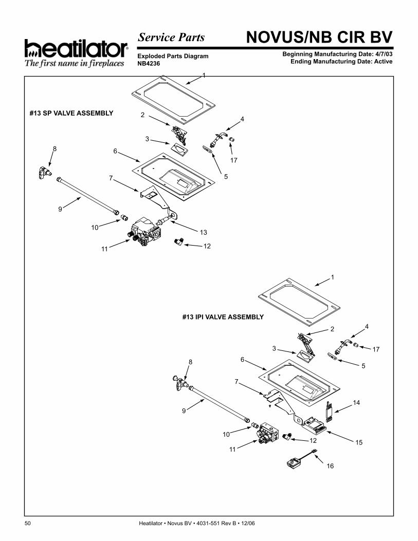
50 Heatilator • Novus BV • 4031-551 Rev B • 12/06
Exploded Parts DiagramNB4236
Service Parts NOVUS/NB CIR BVBeginning Manufacturing Date: 4/7/03
Ending Manufacturing Date: Active
#13 SP VALVE ASSEMBLY
1
2
3
4
5
6
7
8
9
10
11 12
13
17
#13 IPI VALVE ASSEMBLY
1
2
3
4
56
7
8
9
10
1112
14
15
16
17

Heatilator • Novus BV • 4031-551 Rev B • 12/06 51
Service Parts ListNB4236
Service Parts NOVUS/NB CIR BVBeginning Manufacturing Date: 4/7/03
Ending Manufacturing Date: Active
# Description of Part NB4236 NB4236I Qty.1 Valve Plate Gasket 4031-149 4031-149 12 Pilot Assembly (Pre 12/06) 485-510A 4021-025 12 Pilot Assembly (Post 12/06) 2103-010 4021-422 13 Pilot Gasket 4021-042 4021-042 14 Bulkhead (Pre 12/06) 4031-192 4031-192 14 Bulkhead (Post 12/06) 4031-547 4031-547 15 Bulkhead Gasket 4021-043 4021-043 16 Valve Plate 4031-146 4031-146 17 Valve Bracket (Pre 12/06) 4031-506 4031-506 17 Valve Bracket (Post 12/06) 4031-507 4031-507 18 ON/OFF Valve 15697 15697 19 16 in. Flex Gas Line 17245B 17245B 1
10 Brass Fitting - 3/8 NPT to 3/8 Flare 17069 17069 111 Valve w/Regulator (Pre 12/06) 24033 --- 111 Valve w/Regulator (Post 12/06) 230-0710 --- 111 Variable Dexen Valve --- 750-500 112 Brass Connector - 90 Flex 4021-045 4021-045 113 Push Button Ignitor 291-513 --- 114 Wire Assembly --- 593-590A 115 Control Module --- 593-592 116 3V Adaptor Plug --- 593-593A 117 Threaded Orifi ce (.0935) - NG 4031-159 4031-159 1
Battery Pack - Removed from valve assy, put in install packets --- 593-594A 1Wall Switch Wire Assembly (Pre 12/06) 28602 4018-018 1Wall Switch Wire Assembly (Post 12/06) 4018-018 4018-018 1
24 in. Replacement Pilot Tube Assembly 4021-193 4021-193 1Shoulder Screws 501-836/25 501-836/25 1

52 Heatilator • Novus BV • 4031-551 Rev B • 12/06
Exploded Parts DiagramNB4842
Service Parts NOVUS/NB CIR BVBeginning Manufacturing Date: 4/7/03
Ending Manufacturing Date: Active
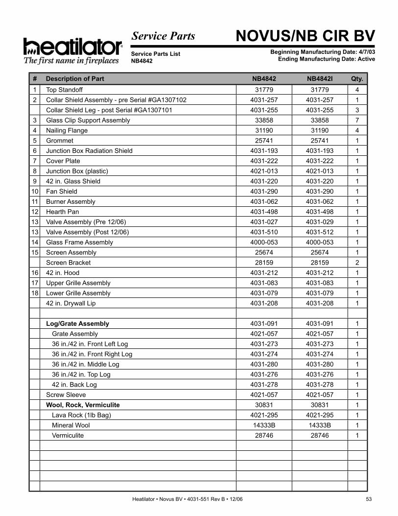
Heatilator • Novus BV • 4031-551 Rev B • 12/06 53
Service Parts ListNB4842
Service Parts NOVUS/NB CIR BVBeginning Manufacturing Date: 4/7/03
Ending Manufacturing Date: Active
# Description of Part NB4842 NB4842I Qty.1 Top Standoff 31779 31779 42 Collar Shield Assembly - pre Serial #GA1307102 4031-257 4031-257 1
Collar Shield Leg - post Serial #GA1307101 4031-255 4031-255 33 Glass Clip Support Assembly 33858 33858 74 Nailing Flange 31190 31190 45 Grommet 25741 25741 16 Junction Box Radiation Shield 4031-193 4031-193 17 Cover Plate 4031-222 4031-222 18 Junction Box (plastic) 4021-013 4021-013 19 42 in. Glass Shield 4031-220 4031-220 1
10 Fan Shield 4031-290 4031-290 111 Burner Assembly 4031-062 4031-062 112 Hearth Pan 4031-498 4031-498 113 Valve Assembly (Pre 12/06) 4031-027 4031-029 113 Valve Assembly (Post 12/06) 4031-510 4031-512 114 Glass Frame Assembly 4000-053 4000-053 115 Screen Assembly 25674 25674 1
Screen Bracket 28159 28159 216 42 in. Hood 4031-212 4031-212 117 Upper Grille Assembly 4031-083 4031-083 118 Lower Grille Assembly 4031-079 4031-079 1
42 in. Drywall Lip 4031-208 4031-208 1
Log/Grate Assembly 4031-091 4031-091 1Grate Assembly 4021-057 4021-057 136 in./42 in. Front Left Log 4031-273 4031-273 136 in./42 in. Front Right Log 4031-274 4031-274 136 in./42 in. Middle Log 4031-280 4031-280 136 in./42 in. Top Log 4031-276 4031-276 142 in. Back Log 4031-278 4031-278 1
Screw Sleeve 4021-057 4021-057 1Wool, Rock, Vermiculite 30831 30831 1
Lava Rock (1lb Bag) 4021-295 4021-295 1Mineral Wool 14333B 14333B 1Vermiculite 28746 28746 1

54 Heatilator • Novus BV • 4031-551 Rev B • 12/06
Exploded Parts DiagramNB4842
Service Parts NOVUS/NB CIR BVBeginning Manufacturing Date: 4/7/03
Ending Manufacturing Date: Active
#13 SP VALVE ASSEMBLY
1
2
3
4
5
6
7
8
9
10
11 12
13
17
#13 IPI VALVE ASSEMBLY
1
2
3
4
56
7
8
9
10
1112
14
15
16
17

Heatilator • Novus BV • 4031-551 Rev B • 12/06 55
Service Parts List
Service Parts NOVUS/NB CIR BVBeginning Manufacturing Date: 4/7/03
Ending Manufacturing Date: Active
# Description of Part NB4842 NB4842I Qty.1 Valve Plate Gasket 4031-149 4031-149 12 Pilot Assembly (Pre 12/06) 485-510A 4021-025 12 Pilot Assembly (Post 12/06) 2103-010 4021-422 13 Pilot Gasket 4021-042 4021-042 14 Bulkhead 4031-192 4031-192 15 Bulkhead Gasket 4021-043 4021-043 16 Valve Plate 4031-146 4031-146 17 Valve Bracket (Pre 12/06) 4031-506 4031-506 17 Valve Bracket (Post 12/06) 4031-507 4031-507 18 ON/OFF Valve 15697 15697 19 16 in. Flex Gas Line 17245B 17245B 1
10 Brass Fitting - 3/8 NPT to 3/8 Flare 17069 17069 111 Valve w/Regulator (Pre 12/06) 24033 111 Valve w/Regulator (Post 12/06) 230-0710 --- 111 Variable Dexen Valve 750-500 112 Brass Connector - 90 Flex 4021-045 4021-045 113 Push Button Ignitor 291-513 114 Wire Assembly 593-590A 115 Control Module 593-592 116 3V Adapter Plug 593-593A 117 Threaded Orifi ce (.104) - NG 4031-158 4031-158 1
Battery Pack - Removed from valve assy, put in install packets 593-594A 1Wall Switch Wire Assembly (Pre 12/06) 28602 4018-018 1Wall Switch Wire Assembly (Post 12/06) 4018-018 4018-018 124 in. Replacement Pilot Tube Assembly 4021-193 4021-193 1Shoulder Screws 501-836/25 501-836/25 1
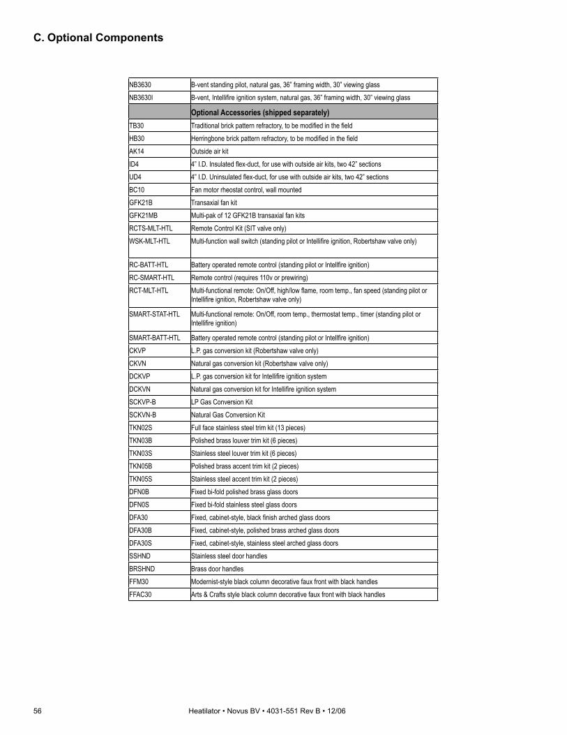
56 Heatilator • Novus BV • 4031-551 Rev B • 12/06
C. Optional Components
NB3630 B-vent standing pilot, natural gas, 36” framing width, 30” viewing glassNB3630I B-vent, Intellifi re ignition system, natural gas, 36” framing width, 30” viewing glass
Optional Accessories (shipped separately)TB30 Traditional brick pattern refractory, to be modifi ed in the fi eldHB30 Herringbone brick pattern refractory, to be modifi ed in the fi eldAK14 Outside air kitID4 4” I.D. Insulated fl ex-duct, for use with outside air kits, two 42” sectionsUD4 4” I.D. Uninsulated fl ex-duct, for use with outside air kits, two 42” sectionsBC10 Fan motor rheostat control, wall mountedGFK21B Transaxial fan kitGFK21MB Multi-pak of 12 GFK21B transaxial fan kitsRCTS-MLT-HTL Remote Control Kit (SIT valve only)WSK-MLT-HTL Multi-function wall switch (standing pilot or Intellifi re ignition, Robertshaw valve only)
RC-BATT-HTL Battery operated remote control (standing pilot or Intellfi re ignition)RC-SMART-HTL Remote control (requires 110v or prewiring)RCT-MLT-HTL Multi-functional remote: On/Off, high/low fl ame, room temp., fan speed (standing pilot or
Intellifi re ignition, Robertshaw valve only)
SMART-STAT-HTL Multi-functional remote: On/Off, room temp., thermostat temp., timer (standing pilot or Intellifi re ignition)
SMART-BATT-HTL Battery operated remote control (standing pilot or Intellfi re ignition)CKVP L.P. gas conversion kit (Robertshaw valve only)CKVN Natural gas conversion kit (Robertshaw valve only)DCKVP L.P. gas conversion kit for Intellifi re ignition systemDCKVN Natural gas conversion kit for Intellifi re ignition systemSCKVP-B LP Gas Conversion KitSCKVN-B Natural Gas Conversion KitTKN02S Full face stainless steel trim kit (13 pieces)TKN03B Polished brass louver trim kit (6 pieces)TKN03S Stainless steel louver trim kit (6 pieces)TKN05B Polished brass accent trim kit (2 pieces)TKN05S Stainless steel accent trim kit (2 pieces)DFN0B Fixed bi-fold polished brass glass doorsDFN0S Fixed bi-fold stainless steel glass doorsDFA30 Fixed, cabinet-style, black fi nish arched glass doorsDFA30B Fixed, cabinet-style, polished brass arched glass doorsDFA30S Fixed, cabinet-style, stainless steel arched glass doorsSSHND Stainless steel door handlesBRSHND Brass door handlesFFM30 Modernist-style black column decorative faux front with black handlesFFAC30 Arts & Crafts style black column decorative faux front with black handles

Heatilator • Novus BV • 4031-551 Rev B • 12/06 57
Model # DescriptionNB3933 B-vent, standing pilot, natural gas, 39” framing width, 33” viewing glassNB3933I B-vent, Intellifi re ignition system, natural gas, 39” framing width, 33” viewing glass
Optional Accessories (shipped separately)TB33 Traditional brick pattern refractory, to be modifi ed in the fi eldHB33 Herringbone brick pattern refractory, to be modifi ed in the fi eldAK14 Outside air kitID4 4” I.D. Insulated fl ex-duct, for use with outside air kits, two 42” sectionsUD4 4” I.D. Uninsulated fl ex-duct, for use with outside air kits, two 42” sectionsBC10 Fan motor rheostat control, wall mountedGFK4B Transaxial fan kitGFK4MB Multi-pak of 12 GFK4B transaxial fan kitsRCTS-MLT-HTL Remote Control Kit (SIT valve only)WSK-MLT-HTL Multi-function wall switch (standing pilot or Intellifi re ignition, Robertshaw valve only)
RC-BATT-HTL Battery operated remote control (standing pilot or Intellfi re ignition)RC-SMART-HTL Remote control (requires 110v or prewiring)RCT-MLT-HTL Multi-functional remote: On/Off, high/low fl ame, room temp., fan speed (standing pilot or
Intellifi re ignition, Robertshaw valve only)
SMART-STAT-HTL Multi-functional remote: On/Off, room temp., thermostat temp., timer (standing pilot or Intellifi re ignition)
SMART-BATT-HTL Battery operated remote control (standing pilot or Intellfi re ignition)CKVP L.P. gas conversion kit (Robertshaw valve only)CKVN Natural gas conversion kit (Robertshaw valve only)DCKVP L.P. gas conversion kit for Intellifi re ignition systemDCKVN Natural gas conversion kit for Intellifi re ignition systemSCKVP-B LP Gas Conversion KitSCKVN-B Natural Gas Conversion KitTKN32S Full face stainless steel trim kit (13 pieces) (decorative unit only)TKN33B Polished brass louver trim kit (6 pieces)TKN33S Stainless steel louver trim kit (6 pieces)TKN35B Polished brass accent trim kit (2 pieces)TKN35S Stainless steel accent trim kit (2 pieces)DFN3B Fixed bi-fold polished brass glass doorsDFN3S Fixed bi-fold stainless steel glass doorsDFA33 Fixed cabinet-style, arched, black fi nish glass doorsDFA33B Fixed cabinet-style, arched, polished brass glass doorsDFA33S Fixed cabinet-style, arched, stainless steel glass doorsSSHND Stainless steel door handlesBRSHND Brass door handlesFFM33 Modernist-style black column decorative faux front with black handlesFFAC33 Arts & Crafts style black column decorative faux front with black handles
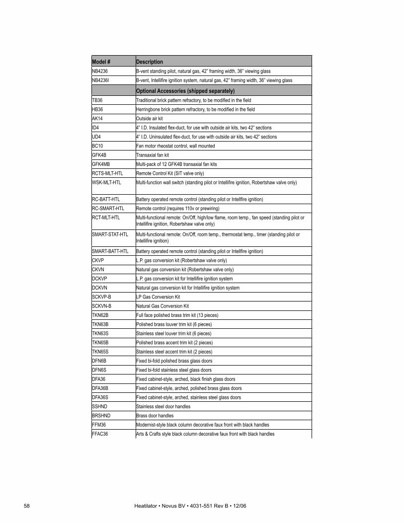
58 Heatilator • Novus BV • 4031-551 Rev B • 12/06
Model # DescriptionNB4236 B-vent standing pilot, natural gas, 42” framing width, 36” viewing glassNB4236I B-vent, Intellifi re ignition system, natural gas, 42” framing width, 36” viewing glass
Optional Accessories (shipped separately)TB36 Traditional brick pattern refractory, to be modifi ed in the fi eldHB36 Herringbone brick pattern refractory, to be modifi ed in the fi eldAK14 Outside air kitID4 4” I.D. Insulated fl ex-duct, for use with outside air kits, two 42” sectionsUD4 4” I.D. Uninsulated fl ex-duct, for use with outside air kits, two 42” sectionsBC10 Fan motor rheostat control, wall mountedGFK4B Transaxial fan kitGFK4MB Multi-pack of 12 GFK4B transaxial fan kitsRCTS-MLT-HTL Remote Control Kit (SIT valve only)WSK-MLT-HTL Multi-function wall switch (standing pilot or Intellifi re ignition, Robertshaw valve only)
RC-BATT-HTL Battery operated remote control (standing pilot or Intellfi re ignition)RC-SMART-HTL Remote control (requires 110v or prewiring)RCT-MLT-HTL Multi-functional remote: On/Off, high/low fl ame, room temp., fan speed (standing pilot or
Intellifi re ignition, Robertshaw valve only)
SMART-STAT-HTL Multi-functional remote: On/Off, room temp., thermostat temp., timer (standing pilot or Intellifi re ignition)
SMART-BATT-HTL Battery operated remote control (standing pilot or Intellfi re ignition)CKVP L.P. gas conversion kit (Robertshaw valve only)CKVN Natural gas conversion kit (Robertshaw valve only)DCKVP L.P. gas conversion kit for Intellifi re ignition systemDCKVN Natural gas conversion kit for Intellifi re ignition systemSCKVP-B LP Gas Conversion KitSCKVN-B Natural Gas Conversion KitTKN62B Full face polished brass trim kit (13 pieces)TKN63B Polished brass louver trim kit (6 pieces)TKN63S Stainless steel louver trim kit (6 pieces)TKN65B Polished brass accent trim kit (2 pieces)TKN65S Stainless steel accent trim kit (2 pieces)DFN6B Fixed bi-fold polished brass glass doorsDFN6S Fixed bi-fold stainless steel glass doorsDFA36 Fixed cabinet-style, arched, black fi nish glass doorsDFA36B Fixed cabinet-style, arched, polished brass glass doorsDFA36S Fixed cabinet-style, arched, stainless steel glass doorsSSHND Stainless steel door handlesBRSHND Brass door handlesFFM36 Modernist-style black column decorative faux front with black handlesFFAC36 Arts & Crafts style black column decorative faux front with black handles

Heatilator • Novus BV • 4031-551 Rev B • 12/06 59
Model # DescriptionNB4842 B-vent standing pilot, natural gas, 48” framing width, 42” viewing glassNB4842I B-vent, Intellifi re ignition system, natural gas, 48” framing width, 42” viewing glass
Optional Accessories (shipped separately)TB42 Traditional brick pattern refractory, to be modifi ed in the fi eldHB42 Herringbone brick pattern refractory, to be modifi ed in the fi eldAK14 Outside air kitID4 4” I.D. Insulated fl ex-duct, for use with outside air kits, two 42” sectionsUD4 4” I.D. Uninsulated fl ex-duct, for use with outside air kits, two 42” sectionsBC10 Fan motor rheostat control, wall mountedGFK4B Transaxial fan kitGFK4MB Multi-pack of 12 GFK4B transaxial fan kitsRCTS-MLT-HTL Remote Control Kit (SIT valve only)WSK-MLT-HTL Multi-function wall switch (standing pilot or Intellifi re ignition, Robertshaw valve only)
RC-BATT-HTL Battery operated remote control (standing pilot or Intellfi re ignition)RC-SMART-HTL Remote control (requires 110v or prewiring)RCT-MLT-HTL Multi-functional remote: On/Off, high/low fl ame, room temp., fan speed (standing pilot or
Intellifi re ignition, Robertshaw valve only)
SMART-STAT-HTL Multi-functional remote: On/Off, room temp., thermostat temp., timer (standing pilot or Intellifi re ignition)
SMART-BATT-HTL Battery operated remote control (standing pilot or Intellfi re ignition)CKVP L.P. gas conversion kit (Robertshaw valve only)CKVN Natural gas conversion kit (Robertshaw valve only)DCKVP L.P. gas conversion kit for Intellifi re ignition systemDCKVN Natural gas conversion kit for Intellifi re ignition systemSCKVP-B LP Gas Conversion KitSCKVN-B Natural Gas Conversion KitTKN22B Full face polished brass trim kitTKN22S Full face stainless steel trim kitTKN23B Polished brass trim kit (5 pieces)TKN23S Stainless steel trim kit (5 pieces)TKN25B Polished brass trim kit (2 pieces)TKN25S Stainless steel trim kit (2 pieces)DFC2B Fixed bi-fold polished brass glass doorsDFC2S Fixed bi-fold stainless steel glass doorsDFA42 Fixed cabinet-style, arched, black fi nish glass doorsDFA42B Fixed cabinet-style, arched, polished brass glass doorsDFA42S Fixed cabinet-style, arched, stainless steel glass doorsSSHND Stainless steel door handlesBRSHND Brass door handlesFFM42 Modernist-style black column decorative faux front with black handlesFFAC42 Arts & Crafts style black column decorative faux front with black handles
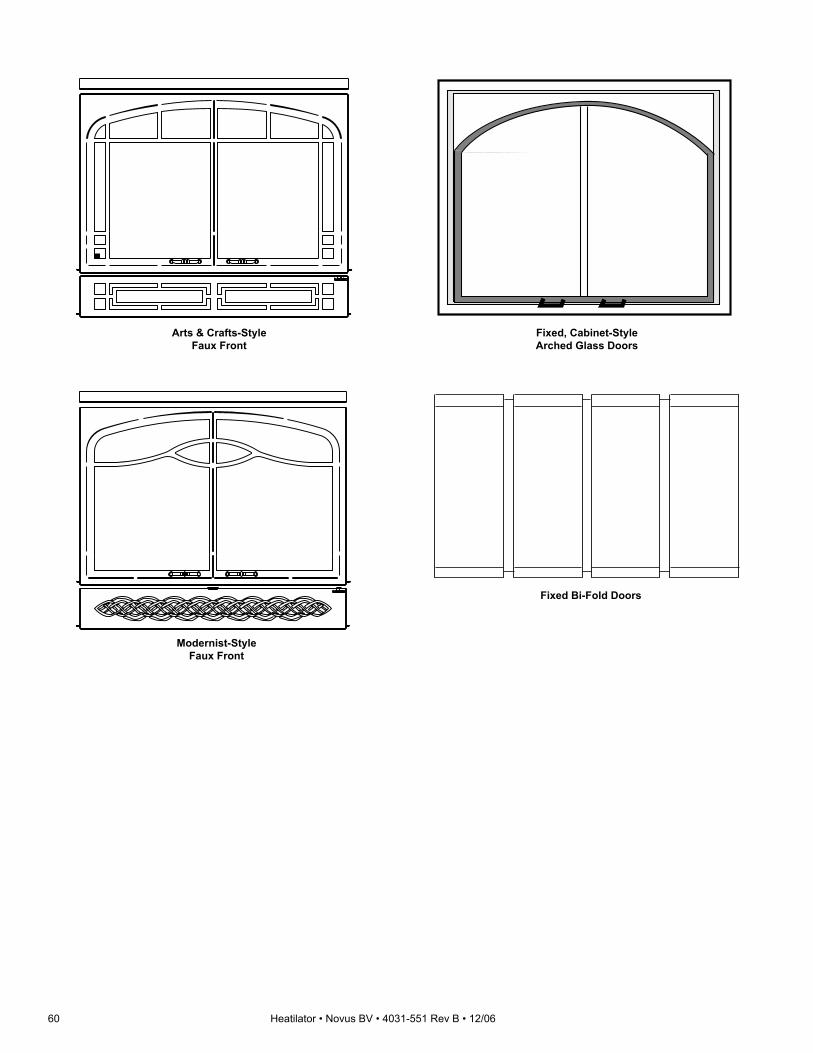
60 Heatilator • Novus BV • 4031-551 Rev B • 12/06
Arts & Crafts-StyleFaux Front
Modernist-StyleFaux Front
Fixed, Cabinet-StyleArched Glass Doors
Fixed Bi-Fold Doors

Heatilator • Novus BV • 4031-551 Rev B • 12/06 61
Center piece is notpart of the refractoryfor the 3630 model
TB33Traditional Brick Refractory
Center piece is not part of the refractory for the
3630 model.
HB33Herringbone Brick Refractory

62 Heatilator • Novus BV • 4031-551 Rev B • 12/06
This page intentionally left blank.

Heatilator • Novus BV • 4031-551 Rev B • 12/06 63
Gas Appliance (Fireplace)Limited Lifetime Warranty
HEARTH & HOME TECHNOLOGIES INC. (“HHT”) extends the following warranty for HEATILATOR® gas appliances installed in the United States of America or Canada (the "Appliance"). Dealers and employees of HHT have no authority to make any warranty or authorize any remedies in addition to or inconsistent with the terms of this warranty. Limited Lifetime WarrantyHHT warrants the Appliance for component failure due to a manufacturing defect of any of the following components: combustion chamber, burner pan, and logs. The Limited Lifetime Warranty specifi ed above is subject to the conditions, exclusions and limitations listed below, is for the period the Appliance is owned by the original homeowner only, and is nontransferable.
1 Year Limited WarrantyHHT warrants the Appliance to be free from failure of any of the following components for a period of one year after installation: valve, fl exible gas line connector, glass panel, fan, direct vent chimney components, factory paint, gasket, piezo ignitor, thermopile, thermocouple, junction box, pilot assembly, shutoff valve, high limit switch, refractory liners, transformer, and control box. If the Heatilator Appliance is found to be defective in either material or workmanship within one year of the date of original installation, HHT will provide replacement parts at no charge and pay reasonable labor and freight costs, and is for the period of one year following the date of original installation of the Appliance.
Conditions, Exclusions, & Limitations of LiabilityA. Both the Limited Lifetime and 1 Year Limited Warranties supplied by HHT apply only while the Appliance is in its location of original
installation. HHT’s obligation under this warranty does not extend to damages resulting from (1) installation, operation or maintenance of the Appliance not in accordance with the Installation Instructions, Operating Instructions, and the Listing Agent Identifi cation Label furnished with the Appliance; (2) installation which does not comply with local building codes; (3) shipping, improper handling, improper operation, abuse, misuse, accident or unworkmanlike repairs; (4) environmental conditions, inadequate ventilation or drafting caused by tight sealing construction of the structure, air handling devices such as exhaust fans or forced air furnaces, or other causes; (5) use of fuels other than those specifi ed in the Operating Instructions; (6) installation or use of components not supplied with the Appliance or any other components not expressly authorized and approved by HHT; and/or (7) modifi cation of the Appliance not expressly authorized and approved by HHT in writing. This warranty is limited to only the component parts manufactured or supplied by HHT.
B. HHT’s liability under both the Limited Lifetime Warranty and the 1 Year Limited Warranty is limited to the replacement and repair of defective components or workmanship during the applicable period. HHT may fully discharge all of its obligations under such warranties by repairing the defective component(s) or at HHT’s discretion, providing replacement parts at no charge and paying reasonable labor and freight costs.
C. EXCEPT TO THE EXTENT PROVIDED BY LAW, HHT MAKES NO EXPRESS WARRANTIES OTHER THAN THE WARRANTY SPECIFIED HEREIN. THE DURATION OF ANY IMPLIED WARRANTY IS LIMITED TO DURATION OF THE WARRANTY SPECIFIED ABOVE.
D. Some states do not allow exclusions or limitations of incidental or consequential damages, so those limitations may not apply to you. This warranty gives you specifi c rights; you may also have other rights which vary from state to state.
How to Obtain ServiceTo obtain service under this warranty you must:1. Send written notice of the claimed condition to Heatilator Technical Service Department, Hearth & Home Technologies, 1915 W.
Saunders Street, Mt. Pleasant, Iowa 52641-1563. You may also register your claim online at www.heatilator.com.2. Provide proof of purchase, model number, serial number, and manufacturing date code to HHT.3. Provide HHT reasonable opportunity to investigate the claim, including reasonable opportunity to inspect the Appliance prior to any
repair or replacement work and before the Appliance or any component of the Appliance has been removed from the place of original installation.
4. Obtain HHT’s consent to any warranty work before the work is done.
ADDITIONAL INFORMATION: If you would like information on current HEATILATOR products or want to locate a dealer in your area, call 1-800-927-6841.
©2003 Heatilator® is a Registered Trademark of Hearth & Home Technologies Inc.
D. Limited Lifetime Warranty

64 Heatilator • Novus BV • 4031-551 Rev B • 12/06
E. Contact Information
Hearth & Home Technologies Inc.
1915 W. Saunders Street
Mt. Pleasant, Iowa 52641
www.heatilator.com
- NOTES -
DO NOT DISCARD THIS MANUALCAUTION
• Important operating and ma in tenance instructions included.
• L e a v e t h i s manual with party responsible for use and operation.
• Read, understand and fol low these instructions for safe i n s t a l l a t i o n a n d operation.
DO
NOT
DIS
CARD
This product may be covered by one or more of the following patents: (United States) 4593510, 4686807, 4766876, 4793322, 4811534, 5000162, 5016609, 5076254, 5113843, 5191877, 5218953, 5263471, 5328356, 5341794, 5347983, 5429495, 5452708, 5542407, 5601073, 5613487, 5647340, 5688568, 5762062, 5775408, 5890485, 5931661, 5941237, 5947112, 5996575, 6006743, 6019099, 6048195, 6053165, 6145502, 6170481, 6237588, 6296474, 6374822, 6413079, 6439226, 6484712, 6543698, 6550687, 6601579, 6672860, 6688302B2, 6715724B2, 6729551, 6736133, 6748940, 6748942, 6769426, 6774802, 6796302, 6840261, 6848441, 6863064, 6866205, 6869278, 6875012, 6880275, 6908039, 6919884, D320652, D445174, D462436; (Canada) 1297749, 2195264, 2225408, 2313972; (Australia) 780250, 780403, 1418504 or other U.S. and foreign patents pending.
Please contact your Heatilator dealer with any questions or concerns. For the number of your nearest Heatilator dealer, please visit www.heatilator.com.