Installation and Operation - - APC USA · Remote Distribution Panel—Installation and Operation i...
32
Rack Distribution Panel Installation and Operation
-
Upload
phungkhanh -
Category
Documents
-
view
220 -
download
0
Transcript of Installation and Operation - - APC USA · Remote Distribution Panel—Installation and Operation i...

Rack Distribution Panel
Installation and Operation


About this Manual
This manual is intended for end-users of the Rack Distribution Panel (RDP). It covers the installation, operation, and basic maintenance of the RDP and assumes that the RDP is bundled with an InfraStruXure 80kW PDU with System Bypass. If you did not purchase an 80kW PDU with your RDP, some of the procedures in this manual do not apply.
For information about installing equipment in the RDP enclosure, joining the RDP enclosure to a NetShelter enclosure, or modifying the RDP enclosure, see the NetShelter VX Installation manual (990-0393C) included with the RDP.
For additional information about the InfraStruXure 80kW PDU with System Bypass, see the following manuals:
• The InfraStruXure 80kW Installation and Start-Up manual (990-1467) covers the installation, start-up, and configuration of an entire Type B 80kW InfraStruXure power and rack system.
• The 80kW utility connection instruction sheet (990-1469) provides specific instructions for the electrician connecting power to the PDU with System Bypass.
• The PDU with System Bypass 80kW Operation and Maintenance manual covers system operation and operation and basic maintenance of an 80kW PDU with System Bypass.
Remote Distribution Panel—Installation and Operation i


Contents
Safety ......................................................................1
Overview . . . . . . . . . . . . . . . . . . . . . . . . . . . . . . . . . . . . . . . . . 1Safety symbols used in this guide . . . . . . . . . . . . . . . . . . . . . 1
Warnings . . . . . . . . . . . . . . . . . . . . . . . . . . . . . . . . . . . . . . . . . 2Installation/Maintenance . . . . . . . . . . . . . . . . . . . . . . . . . . 2
Maintenance performed while the RDP is receiving power . . . . 2
DANGER—Risk of Electric Shock! . . . . . . . . . . . . . . . . . . . . . 2
Overview .................................................................3
RDP Components . . . . . . . . . . . . . . . . . . . . . . . . . . . . . . . . . . . 3Recycle . . . . . . . . . . . . . . . . . . . . . . . . . . . . . . . . . . . . . . 4
Receiving Inspection . . . . . . . . . . . . . . . . . . . . . . . . . . . . . 4
Disclaimer . . . . . . . . . . . . . . . . . . . . . . . . . . . . . . . . . . . . 4
Installation...............................................................5
Level the RDP Enclosure . . . . . . . . . . . . . . . . . . . . . . . . . . . . . . 5
Install the Shielding Trough. . . . . . . . . . . . . . . . . . . . . . . . . . . . 6
Apply Power . . . . . . . . . . . . . . . . . . . . . . . . . . . . . . . . . . . . . . . 8Connect the sub-feed power cable conductors to a three-pole breaker on the PDU . . . . . . . . . . . . . . . . . . . 8
Alternative connection: connect the sub-feed power cables . . . 9
Route and attach power cables to equipment racks . . . . . . . . 9
Apply power to connected equipment . . . . . . . . . . . . . . . . 11
Install Equipment into the RDP Enclosure . . . . . . . . . . . . . . . . 12How to identify one U-space on the mounting rail . . . . . . . . 12
How to install caged nuts . . . . . . . . . . . . . . . . . . . . . . . . . 13
Remote Distribution Panel—Installation and Operation iii

Maintenance ......................................................... 15
Important Safety Instructions . . . . . . . . . . . . . . . . . . . . . . . . . . 15
Orderable Parts from APC . . . . . . . . . . . . . . . . . . . . . . . . . . . . 16
How to Add Circuit Breakers and Power Cables. . . . . . . . . . . . . . . . . . . . . . . . . . . . . . . . . . . . . . 17
Add a circuit breaker on the RDP . . . . . . . . . . . . . . . . . . . . 17
Add a power cable to the RDP . . . . . . . . . . . . . . . . . . . . . 18
Product Information .............................................. 19
Specifications. . . . . . . . . . . . . . . . . . . . . . . . . . . . . . . . . . . . . . 19
Warranty. . . . . . . . . . . . . . . . . . . . . . . . . . . . . . . . . . . . . . . . . 21
Life-Support Policy . . . . . . . . . . . . . . . . . . . . . . . . . . . . . . . . . . 22
How to Obtain Service. . . . . . . . . . . . . . . . . . . . . . . . . . . . . . . 23
iv Remote Distribution Panel—Installation and Operation

Safety
Overview
Safety symbols used in this guide
Save these instructions. This manual contains important instructions that must be followed during installation, operation, and maintenance of the RDP.
ElectricalHazard
Indicates a hazard, which, if not avoided, could result in injury or death.
Warning
Indicates a hazard, which, if not avoided, could result in damage to product or other property.
Note
Indicates important information.
Heavy
Indicates a heavy load that should not be lifted without assistance.
Indicates that more information is available on the same subject in a different section of this manual.
See also
Indicates that more information is available on the same subject in a different manual.
Remote Distribution Panel—Installation and Operation 1

Warnings
Installation/Maintenance
Only a certified electrician can install a customer-specified, hard-wired power cable to the RDP.
Only a certified electrician or an APC Field Service Engineer can perform maintenance of the Rack Distribution Panel (RDP).
Maintenance performed while the RDP is receiving power
APC does not recommend that you perform maintenance of the RDP while it is receiving input power. If you must perform maintenance while the RDP is receiving input power, observe the following precautions to reduce the risk of electric shock:
1. Never work alone.
2. Perform the maintenance only if you are a certified electrician who is trained in the hazards of live electrical installation.
3. Know the procedure for disconnecting electricity to the RDP and the data center in case of an emergency.
4. Wear appropriate personal protective equipment.
5. Use double-insulated tools.
6. Always follow local and site regulations when working on the RDP.
DANGER—Risk of Electric Shock!
ElectricalHazard
Hazardous, electrically-charged parts may exist inside the RDP from the attached UPS’s inverter even when the data center’s AC power is disconnected. Test any electrical parts before touching them.
2 Remote Distribution Panel—Installation and Operation

Overview
RDP Components
�
�
�
�
� Power cable—The power cables exit from knockout panels on the roof of the RDP enclosure. The power cables consist of five wires (three phases, one neutral, and one ground). The number of power cables installed in the RDP depends on your system configuration. Each power cable terminates with a NEMA L21-20 outlet, which accepts a variety of APC InfraStruXure power accessories, including Rack PDUs and the Rack ATS.
� Sub-feed power cable—The power cable consists of five wires (three phases, one neutral, and one ground), and terminates with an IEC 309 plug. If you have an 80kW PDU as part of your system, this power cable attaches to a sub-feed power cable from the PDU.
� Available rack space—The RDP provides 32U of space in the lower part of the enclosure for installing rack-mount equipment. See the NetShelter VX manual (provided) for information specific to installing equipment in the RDP enclosure.
� 42-position circuit breaker panel—Each RDP has one circuit breaker panel with 42 pole positions. Three pole positions back-feed the RDP and three pole positions provide power to an L21-20 outlet that can connect to a Rack PDU installed in the RDP enclosure. The remaining 36 pole positions are available to provide power to equipment racks and enclosures. Each pole provides power at 120 volts L-N or 208V L-L. The amperage each position provides depends on the rating of the circuit breaker used.
Remote Distribution Panel—Installation and Operation 3

Overview—RDP Components
Recycle
Receiving Inspection
After unpacking the RDP, verify that your shipment matches the Bill of Lading. If any items are missing, contact APC Customer Support at a number on the back cover of this manual.
Disclaimer
APC is not responsible for damage sustained during reshipment of this product.
The shipping materials are recyclable. Please save them for later use, or dispose of them appropriately.
4 Remote Distribution Panel—Installation and Operation

Installation
Level the RDP Enclosure
Leveling feet are attached under the enclosure with one at each corner. The leveling feet help provide a stable base if the selected floor space is uneven, but they cannot compensate for a severely sloped surface. To level the enclosure:
1. For each leveling foot, fit the 14-millimeter end of the open-ended wrench (provided) to the hex head just above the round pad on the bottom of the leveling foot. Turn the wrench clockwise to extend the leveling foot until it makes firm contact with the floor.
2. Use a level to determine which feet need further adjustment to level the enclosure. Adjust them as necessary.
Remote Distribution Panel—Installation and Operation 5
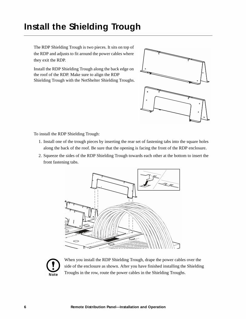
Install the Shielding Trough
The RDP Shielding Trough is two pieces. It sits on top of the RDP and adjusts to fit around the power cables where they exit the RDP.
Install the RDP Shielding Trough along the back edge on the roof of the RDP. Make sure to align the RDP Shielding Trough with the NetShelter Shielding Troughs.
To install the RDP Shielding Trough:
1. Install one of the trough pieces by inserting the rear set of fastening tabs into the square holes along the back of the roof. Be sure that the opening is facing the front of the RDP enclosure.
2. Squeeze the sides of the RDP Shielding Trough towards each other at the bottom to insert the front fastening tabs.
Note
When you install the RDP Shielding Trough, drape the power cables over the side of the enclosure as shown. After you have finished installing the Shielding Troughs in the row, route the power cables in the Shielding Troughs.
6 Remote Distribution Panel—Installation and Operation

Installation—Install the Shielding Trough
3. Install the other RDP Shielding Trough in the same manner, aligning it with the front of the adjacent NetShelter Trough. Be sure that the opening is facing the rear of the enclosure.
Note
Before applying power, install your APC rack power distribution equipment in the racks to which the RDP will be distributing power.
Remote Distribution Panel—Installation and Operation 7

Apply Power
Connect the sub-feed power cable conductors to a three-pole breaker on the PDU
The sub-feed power cable is connected to the RDP and the cable’s wires are terminated with ferrules. To connect the sub-feed power cable to the PDU:
1. Route the sub-feed power cable from the RDP to the PDU through the Shielding Troughs.
2. Route each phase conductor (L1, L2, L3) through a current sensor (secured to the PDU enclosure) and secure the current sensor to each conductor using a wire tie (provided).
3. Connect the power cable’s individual wires (see the illustration below):
a. Connect each phase conductor (L1, L2, L3) to the appropriate pole on one of the three-pole breakers (sub-feed breakers) at the bottom of the panel.
b. Connect the neutral wire to a termination point on the neutral bar at the top of the distribution panel.
c. Connect the ground wire to a ground lug at the bottom of the distribution panel.
ElectricalHazard
Only licensed electricians or APC Field Service Engineers can connect the sub-feed power cable conductors to a breaker on the PDU. Ensure that the RDP breakers are OFF before beginning this procedure.
N
G
8 Remote Distribution Panel—Installation and Operation

Installation—Apply Power
Alternative connection: connect the sub-feed power cables
If you have an 80kW PDU with System Bypass as part of your system and you ordered the alternate connection method, connect the sub-feed power cable on the RDP to a sub-feed power cable on the PDU. The RDP cable terminates with an IEC 309 plug and the PDU cable terminates with an IEC 309 outlet.
Route and attach power cables to equipment racks
To connect the pre-wired power cables of the RDP:
1. Install the Shielding Troughs, Shielding Partitions, and Cable Ladders so that you can route power cables from the RDP to the NetShelter VX Enclosures.
2. Find the numbers that indicate the enclosure to which each power cable will supply power. These numbers are on the roof of the RDP where the power cables exit and on the ends of each power cable.
3. Beginning with the power cables for the enclosures farthest from the RDP, run each power cable within the Shielding Trough along the row and, if necessary, across one or more Cable Ladders to the enclosure to which it will provide power.
4. Connect the appropriate power cable to APC rack power distribution equipment in the enclosure in one of the four following ways:– For single-feed devices without redundancy: Attach a power cable directly to a Rack PDU
installed in a NetShelter VX Enclosure.
ElectricalHazard
Ensure that the RDP breakers are OFF before beginning this procedure.
Note
The enclosures are not numbered. Consult your APC InfraStruXure Configuration Build-Out Tool to determine the enclosure associated with each power cable.
Note
Ensure that the L21-20 twist-lock connector at the end of each power cable always lies on top of any longer power cables in the Shielding Trough.
Remote Distribution Panel—Installation and Operation 9

Installation—Apply Power
– For dual-feed devices within a redundant system: Attach a power cable from each RDP into two different Rack PDUs in the NetShelter VX Enclosure.
– For single-feed devices within a redundant system with a Rack ATS: Connect a power cable to the Rack ATS (A and B feeds), and connect the Rack ATS power cord to a Rack PDU in the NetShelter VX Enclosure.
– For dual-feed devices in a redundant system with a Rack ATS: Connect a power cable from each RDP to the Rack ATS (A and B feeds), and another power cable from one RDP to a Rack PDU, and the Rack ATS’s power cord to a second Rack PDU in the NetShelter VX Enclosure.
10 Remote Distribution Panel—Installation and Operation

Installation—Apply Power
5. From each NetShelter VX Enclosure, run the power cable of the appropriate APC power management device out the roof of the enclosure, through the notch in the rear side of the Shielding Trough, and to the connector of the appropriate power cable from the RDP. Plug the two connectors together, and twist them clockwise to lock them.
Apply power to connected equipment
To apply power to connected equipment, close (turn ON) the RDP distribution panel breakers.
Note
The APC InfraStruXure Build-Out Tool allows you to attach three 20A, single-pole breakers to one three-phase power cable if you are powering 120V (L-N) loads. However, if you are powering 208V (L-L) loads, you must attach a three-phase power cable to one three-pole, 20A breaker.
Remote Distribution Panel—Installation and Operation 11

Install Equipment into the RDP Enclosure
The RDP provides 32U of space in the lower part of the enclosure for installing rack-mount equipment. A circuit breaker on the RDP distribution panel provides power to an L21-20 receptacle located in the rear of the RDP to provide power to a Rack PDU for equipment installed in the RDP enclosure. This section provides general information on installing rack-mount equipment in the RDP enclosure. Read the instructions provided with the equipment you are installing and the NetShelter VX manual (provided) for specific procedures.
How to identify one U-space on the mounting rail
When installing equipment, locate the top and bottom of a U-space on the mounting rails. Every third hole on the mounting rails of a NetShelter enclosure is numbered to indicate the middle of a U-space. A U-space consists of the rack space adjacent to one of these numbered holes and one hole directly above and below it, as shown.
19
1 U 20
21
12 Remote Distribution Panel—Installation and Operation

Installation—Install Equipment into the RDP Enclosure
How to install caged nuts
To install equipment in the enclosure, use the caged nuts provided with your enclosure.
1. Insert the caged nut into the square hole by hooking one ear of the caged nut assembly through the far side of the hole.
2. Place the caged nut tool (provided) on the other ear of the caged nut and pull to snap it into position.
Warning
Install caged nuts horizontally, with the ears engaging the sides of the square hole. Do NOT install caged nuts vertically with the ears engaging the top and bottom of the square hole.
Note
Install the caged nuts on the interior of the mounting rails.
Remote Distribution Panel—Installation and Operation 13


Maintenance
Important Safety Instructions
ElectricalHazard
APC does not recommend that you perform maintenance of the RDP while it is receiving input power. If you must perform maintenance while the RDP is receiving input power, observe the following precautions to reduce the risk of electric shock:
1. Never work alone.
2. Perform the maintenance only if you are a certified electrician who is trained in the hazards of live electrical installation.
3. Know the procedure for disconnecting electricity to the RDP and the data center in case of an emergency.
4. Wear appropriate personal protective equipment.
5. Use double-insulated tools.
6. Always follow local and site regulations when working on the RDP.
Remote Distribution Panel—Installation and Operation 15

Orderable Parts from APC
Breakers
PD1P20ABBSD 20-amp, single-pole breaker
PD3P20ABBSD 20-amp, three-pole breaker
Power Cables
PDW5L21-20R 5-foot power cable PDW35L21-20R 35-foot power cable
PDW7L21-20R 7-foot power cable PDW37L21-20R 37-foot power cable
PDW9L21-20R 9-foot power cable PDW39L21-20R 39-foot power cable
PDW11L21-20R 11-foot power cable PDW41L21-20R 41-foot power cable
PDW13L21-20R 13-foot power cable PDW43L21-20R 43-foot power cable
PDW15L21-20R 15-foot power cable PDW45L21-20R 45-foot power cable
PDW17L21-20R 17-foot power cable PDW47L21-20R 47-foot power cable
PDW19L21-20R 19-foot power cable PDW49L21-20R 49-foot power cable
PDW21L21-20R 21-foot power cable PDW51L21-20R 51-foot power cable
PDW23L21-20R 23-foot power cable PDW53L21-20R 53-foot power cable
PDW25L21-20R 25-foot power cable PDW55L21-20R 55-foot power cable
PDW27L21-20R 27-foot power cable PDW57L21-20R 57-foot power cable
PDW29L21-20R 29-foot power cable PDW59L21-20R 59-foot power cable
PDW31L21-20R 31-foot power cable PDW61L21-20R 61-foot power cable
PDW33L21-20R 33-foot power cable PDW63L21-20R 63-foot power cable
16 Remote Distribution Panel—Installation and Operation

How to Add Circuit Breakers and Power Cables
Add a circuit breaker on the RDP
1. Snap and bolt the new breaker into a position on the panel.
2. Remove the corresponding plastic blanking plate on the front panel of the RDP.
ElectricalHazard
Only licensed electricians or APC Field Service Engineers can add circuit breakers and power cables to the RDP.
Warning
The APC InfraStruXure Build-Out Tool allows you attach three 20A, single-pole breakers to one three-phase power cable if you are powering 120V (L-N) loads. However, if you are powering 208V (L-L) loads, you must attach a three-phase power cable to one three-pole, 20A breaker.
Remote Distribution Panel—Installation and Operation 17

Maintenance—How to Add Circuit Breakers and Power Cables
Add a power cable to the RDP
Before adding a power cable, add a circuit breaker.
1. Install a strain-relief connector in any available knockout on the roof of the RDP.
2. Slide enough of the power cable through the strain-relief connector to reach the new circuit breaker.
3. Tighten the strain-relief connector.
4. At the front of the RDP, connect the power cable’s individual wires:
a. Connect the L1, L2, and L3 wires to the circuit breaker(s). The illustration below shows both single and three-pole breakers.
b. Connect the neutral wire to the closest open termination point on the Neutral Bar.
c. Connect the ground wire to the closest open termination point on the Ground Bar.
N
G
18 Remote Distribution Panel—Installation and Operation

Product Information
Specifications
Electrical Specifications
System specification Single-feed, 5 wires
RDP power rating 28.8 kVA
Main AC feed wiring 3W + N + G
Input voltage 208/120V WYE
Maximum input current 80A
Output voltage 208/120V WYE
Operating frequency 60Hz
Over-Current Protection
Main input circuit breaker 80A
Distribution breakers (1-phase and 3-phase) 20A/10kAIC
Subfeed input breaker (3-phase) 80A/10kAIC
Wiring
Main AC input feed IEC309
Local rack power NEMA L21-20R
Power cables to Rack PDUs 3W + N + G (12 AWG)
Power cable connections L21-20 connector system
Power cable wiring top/bottom exit Knock-outs accommodate all pole positions
Remote Distribution Panel—Installation and Operation 19

Product Information—Specifications
Panel Boards
Panel style 3-phase
Number of panels (per RDP) 1
Positions per panel 42
Three-phase breakers per panel 13
Single-phase breakers per panel 39 (3 positions dedicated to L21-20 in rear of RDP)
Panel rating 240V/225A
Breaker pitch ¾ in
Physical
Accessibility—unit Through locked front and rear doors of the enclosure
Accessibility—distribution breakers Through locked RDP front door
Dimensions (L×W×H) 34.5×23.5 ×81.5in (890×610×2060mm)
Shipping dimensions (L×W×H) 48×36×89in (1220×910×2260mm)
Ramp dimensions (L×W) 45×27in (1145×685mm)
Maximum weight 600lb (272kg)
Maximum shipping weight 650lb (295kg)
Service access Front and rear
Service clearance Greater than or equal to 36in (915mm)
Environmental
Environment Indoor use only
Storage temperature range 5 to 113° F (–15 to 45° C)
Operating temperature range 32 to 104° F (0 to 40° C)
Relative humidity 0–95%, non condensing
Standards
Agency approvals UL, cUL
20 Remote Distribution Panel—Installation and Operation

Warranty
InfraStruXureTM Standard Warranty*
The InfraStruXureTM system ships with a 2-year standard warranty. If you purchase all components in the InfraStruXureTM system, APC offers an additional free 1-year warranty. Under this warranty, APC will ship all parts to your site at no cost to be available to you the next business day after APC is notified of the requirement. If you choose to upgrade the system to include an on-site contract, APC offers modular service packages to match your needs.
* All warranties are null and void unless installation and startup are performed by authorized APC Global Services service centers.
Remote Distribution Panel—Installation and Operation 21

Life-Support Policy
APC Three-Phase Systems
American Power Conversion Corporation (APC) and its affiliates and subsidiaries worldwide do not recommend the use of any of their products in life-support applications where failure or malfunction of the APC product can be reasonably expected to cause failure of the life-support device or to significantly affect its safety or effectiveness. APC does not permit the use of any of its products in direct patient care. APC will not knowingly sell its products for use in such applications unless the life-support system or direct patient care device is part of a whole facility/building into which the UPS is integrated, and unless APC receives, in writing, assurances satisfactory to APC that:
a. The UPS system will be configured in a manner that will provide N+1 power redundancy to the critical load,
b. The end-user customer assumes all risks and signs the APC System Configuration and Use Form, and
c. The customer and operators of the APC UPS system agree to indemnify and hold APC and its affiliates and subsidiaries harmless for any and all claims arising out of the systems use in such applications.
The term life-support device includes but is not limited to neonatal oxygen analyzers, nerve stimulators (whether used for anesthesia, pain relief, or other purposes), autotransfusion devices, blood pumps, defibrillators, arrhythmia detectors and alarms, pacemakers, hemodialysis systems, peritoneal dialysis systems, neonatal ventilator incubators, ventilators (for adults and infants), anesthesia ventilators, infusion pumps, and any other devices designated as “critical” by the U.S. FDA.
Hospital-grade wiring devices and leakage current protection may be ordered as options on many APC UPS systems. APC does not claim that units with these modifications are certified or listed as hospital-grade by APC or any other organization. Therefore these units do not meet the requirements for use in direct patient care.
22 Remote Distribution Panel—Installation and Operation

How to Obtain Service
Obtaining service
To obtain support for problems with your InfraStruXure system:0
1. Note the serial number and date of purchase of the component with which you are having problems.
2. Contact Customer Support at a phone number on the back cover of this document. A technician will try to help you solve the problem by phone.
3. If you must return the product, the technician will give you a return material authorization (RMA) number. If the warranty expired, you will be charged for repair or replacement.
4. Pack the unit carefully. The warranty does not cover damage sustained in transit. Enclose a letter with your name, address, RMA number and daytime phone number; a copy of the sales receipt; and a check as payment, if applicable.
5. Mark the RMA number clearly on the outside of the shipping carton.
6. Ship by insured, prepaid carrier to the address provided by the Customer Support technician.
Note
If you ordered on-site service, see your entitlement certificate and review the terms and conditions of the service before you contact APC. An on-site service contract entitles you to an on-site visit by an APC technician to assess the issue, determine the problem, and replace parts, if needed. (Response time varies per contract.)
Remote Distribution Panel—Installation and Operation 23


*990-1492B*
APC Worldwide Customer Support
Customer support for this or any other APC product is available at no charge in any of the following ways:• Visit the APC Web site to find answers to frequently asked questions (FAQs), to access
documents in the APC Knowledge Base, and to submit customer support requests.– www.apc.com (Corporate Headquarters)
Connect to localized APC Web sites for specific countries, each of which provides customer support information.
– www.apc.com/support/Global support with FAQs, knowledge base, and e-support.
• Contact an APC Customer Support center by telephone or e-mail.– Regional centers:
– Local, country-specific centers: go to www.apc.com/support/contact for contact information.
Contact the APC representative or other distributor from whom you purchased your APC product for information on how to obtain local customer support.
Direct InfraStruXure Customer Support Line (1)(877)537-0607 (toll free)
APC headquarters U.S., Canada (1)(800)800-4272 (toll free)
Latin America (1)(401)789-5735 (USA)
Europe, Middle East, Africa (353)(91)702020 (Ireland)
Japan (0) 35434-2021
Entire contents copyright © 2003 American Power Conversion. All rights reserved. Reproduction in whole or in part without permission is prohibited. APC, the APC logo,
InfraStruXure, and NetShelter are trademarks of American Power Conversion Corporation and may be registered in some jurisdictions. All other trademarks, product names, and corporate
names are the property of their respective owners and are used for informational purposes only.
990-1492B 10/2003