
Utility Distribution Systems Installation, Operation, and ... · Utility Distribution Systems...
12
A0011037 February 2018 Utility Distribution Systems Installation, Operation, and Maintenance Manual Save these instructions. This document is the property of the owner of this equipment and is required for future maintenance. Leave this document with the owner when installation or service is complete. RECEIVING AND INSPECTION Upon receiving unit, check for any interior and exterior damage, and if found, report it immediately to the carrier. Also check that all accessory items are accounted for and are damage free. WARNING!! Installation of this module should only be performed by a qualified professional who has read and understands these instructions and is familiar with proper safety precautions. Improper installation poses serious risk of injury due to electric shock and other potential hazards. Read this manual thoroughly before installing or servicing this equipment. ALWAYS disconnect power prior to working on module.
Transcript of Utility Distribution Systems Installation, Operation, and ... · Utility Distribution Systems...
A0011037 February 2018
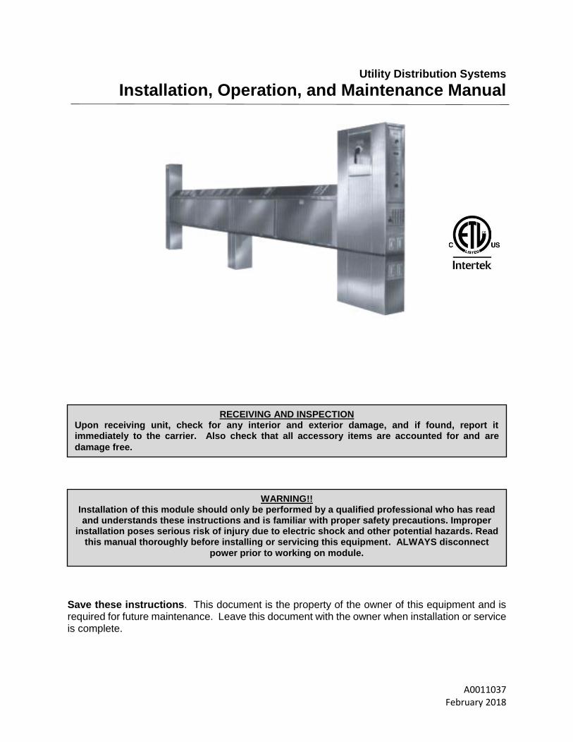
Utility Distribution Systems
Installation, Operation, and Maintenance Manual
Save these instructions. This document is the property of the owner of this equipment and is required for future maintenance. Leave this document with the owner when installation or service is complete.
RECEIVING AND INSPECTION Upon receiving unit, check for any interior and exterior damage, and if found, report it immediately to the carrier. Also check that all accessory items are accounted for and are
damage free.
WARNING!!
Installation of this module should only be performed by a qualified professional who has read and understands these instructions and is familiar with proper safety precautions. Improper
installation poses serious risk of injury due to electric shock and other potential hazards. Read this manual thoroughly before installing or servicing this equipment. ALWAYS disconnect
power prior to working on module.

2
Table of Contents
WARRANTY .................................................................................................................................................. 3 LISTING ........................................................................................................................................................ 3 INSTALLATION ............................................................................................................................................. 4
Product Overview ...................................................................................................................................... 4 Uncrating ................................................................................................................................................... 5 Assembly ................................................................................................................................................... 5 Connection of Utilities ................................................................................................................................ 5 Plumbing .................................................................................................................................................... 5
Plumbing Electrical ................................................................................................................................ 5
Hoses .................................................................................................................................................... 6
Electrical .................................................................................................................................................... 6 Buss Bar ................................................................................................................................................ 6
Wire-Way ............................................................................................................................................... 6
Electrical Outlets and Cord Sets ........................................................................................................... 7
Component Descriptions ........................................................................................................................... 8 Start-Up ......................................................................................................................................................... 9 Service .......................................................................................................................................................... 9
3
WARRANTY
This equipment is warranted to be free from defects in materials and workmanship, under normal use and service, for a period of 24 months from date of shipment. This warranty shall not apply if:
1. The equipment is not installed by a qualified installer per the MANUFACTURER’S installation instructions shipped with the product.
2. The equipment is not installed in accordance with federal, state and local codes and regulations.
3. The equipment is misused or neglected.
4. The equipment is not operated within its published capacity.
5. The invoice is not paid within the terms of the sales agreement.
The MANUFACTURER shall not be liable for incidental and consequential losses and damages potentially attributable to malfunctioning equipment. Should any part of the equipment prove to be defective in material or workmanship within the 24 month warranty period, upon examination by the MANUFACTURER, such part will be repaired or replaced by MANUFACTURER at no charge. The BUYER shall pay all labor costs incurred in connection with such repair or replacement. Equipment shall not be returned without MANUFACTURER’S prior authorization and all returned equipment shall be shipped by the BUYER, freight prepaid to a destination determined by the MANUFACTURER.
LISTING
The Utility Distribution System (UDS) furnished for this job has been built in strict compliance with the National Electric Code and the National Sanitation Foundation Standards. This system is listed under ETL File-3054803-001 and NSF Standard 2.

4
INSTALLATION
Product Overview
The utility distribution system was designed to meet all the utility requirements of your kitchen appliances intended for hook-up to this system. The major components of the system are:
Utility Housing: The raceway system includes risers, pedestals, and exterior panels and is constructed completely of 16-gauge stainless steel. All utility components are housed within this stainless steel enclosure.
Utility Raceway: Plumbing and electrical compartments are entirely enclosed and are accessible through removable panels.
Risers: Single point field connections are done in the vertical chases. These house the main electrical disconnect and plumbing manifold shut off valves, which are accessible through removable panels
Pedestals: May be provided on multiple sections to support the weight of the system.
Figure 1 - UDS- (ISLAND CONFIRURATIONS)
Figure 2 - UDS- (WALL MOUNTED)
5
Uncrating
Use extreme caution when uncrating. This unit is top heavy and can easily turn over. Always store standing up after removing crate. DO NOT LAY UNIT ON ITS SIDE. Switches and valves may extend from the side of the unit. Use caution when moving through doorways or tight areas.
Assembly
Refer to attached drawings or equipment layout to determine the orientation of the UDS. The appliance connections are located for specific appliances and the unit must be installed correctly to supply the intended appliance. Prior to assembly verify that all components have been received. Refer to manufacturer’s Packing List.
Remove the access panels from the riser, pedestal, and raceway, which are adjacent to the field joints.
As the sections are brought together the unions on the plumbing manifolds will require alignment, attachment, and tightening simultaneously. DO NOT FORCE THE THREADED CONNECTIONS. THEY SHOULD BE HAND TIGHTENED SEVERAL TURNS BEFORE USING A WRENCH. DO NOT PULL THE SECTIONS TOGETHER BY TIGHTENING THE FITTINGS. The field connections for the Buss Bar are on the other side. Be sure they are aligned properly.
At each field joint apply a bead of silicone on one of the adjacent surfaces around the opening. Pull the unit together, align holes and install bolts and nuts. Tighten securely.
Install bolts on Buss Bar field joints and tighten.
Connect the wires between the sections at the terminal block. Match color to color or wire number to terminal number.
Re-inspect all field connections. Make sure all are tight and secure.
Connection of Utilities
Connect main electrical feed to main breaker or terminal block. Refer to drawings for location and size of service. Connect plumbing supply to manifolds. Refer to drawings for location and size. Use caution when tightening.
Plumbing
The plumbing section, if supplied, may include gas, hot water, cold water, steam supply, and steam return. The main manifold and individual connections are sized and located for the equipment in the specified design with a 25% future add-on capacity. Plumbing lines are color coded and labeled for identification in field installation. The hot and cold water, steam supply and return manifolds are fiberglass insulated. A main shut off valve is provided for each individual line (¼ turn ball valve) and they are located behind the riser panels (item 2), see Figure 1 and Figure 2. All valves are UL, American Gas Association (AGA) and MA approved.
Plumbing Electrical
Electrical (120VAC) gas solenoid valve(s) will be factory installed in the plumbing riser or provided separately for field installation. NFPA-96 requires that the fuel and electrical supply be shut off to all appliances in the event of a surface fire on any cooking appliance connected to the UDS. Connections must be made per local codes or as suggested in Figure 3. Provisions are made on the shunt trip terminal blocks for connections between surface fire protection and your electrical solenoid gas valve.

6
Hoses
Dual shut-off quick disconnect flexible hoses up to 6 feet long are provided to allow easy access for cleaning, replacement, or removal of equipment. Restraints need to be installed on all mobile equipment to prevent over extending the hoses maximum length. Hoses are UL, AGA and MA approved.
Figure 3 – UDS Connections
Electrical
Electrical service is supplied to the equipment either from a Buss bar or wire-way. These two systems power the equipment in the same manner. Both have shunt trip mechanisms on the main breaker to shut off all electric if the fire system is activated or the emergency kill switch is pressed. The Buss Bar design has point of use breakers located on the top of the horizontal raceway. In the Wire Way design the breakers are located in one of the vertical risers in a breaker panel. Receptacles are usually located at the bottom of the horizontal raceway. If the UDS was designed with duplex convenience outlets they will be located at each end in the vertical risers. This system has been designed for the equipment specified in the job specifications, with a 25% future add-on capacity.
Buss Bar
Each electric service may contain up to (4) conducting copper bars having a balanced load across them. Power from the main breaker feeds the Buss bar. The line side of the branch breakers is connected to the Buss bar and the load side to the appliance receptacle. Extra connection points are located along the Buss to allow relocation or addition of receptacles. These are accessible though doors (item 1), see Figure 1.
Wire-Way
The wire way system consists of a main breaker, which provides electrical power to the Buss in a circuit breaker panel located in one of the vertical risers. In this configuration the branch breakers are located in the breaker panel. Wiring from the breakers run through the horizontal raceway to the receptacle for each appliance. This system may have extra receptacle drops for future equipment.

7
Electrical Outlets and Cord Sets
Each receptacle is provided with a moisture resistant cover and has been located and sized according to the equipment layout specified. Each is supplied with a matching cord and plug set if these are not already supplied with the appliance. Twist-lock sets are standard with UDI. Straight blade sets are standard with UDW.
Optional Equipment
Battery Backup
Bumper Strips
Cable Restraints
Duplex Convenience Outlet (DCO)
Dual Power System
Emergency Kill Switch
Gas Reset
Ground Fault Protection
Hinged Doors
Hood Control Panel Mounted
Mounted TAC-3000, AM2
Hot & Cold Fill Faucets
Hoses For Equipment
Light & Fan Switches
Looped Gas
Electrical Outlets & Cord Sets
Plumbing Fixtures
Prison Package
Over Current Protection
Swivel Connectors
Temperature & Pressure Gauges
Remote Status Indicator Panel
Figure 4 – Electrical Detail
POINT OF USE
CIRCUIT BREAKERS
EQUIPMENT BY OTHERS
GROUNDING TYPE
RECEPTACLE
EQUIPMENT BY OTHERS
CORD AND PLUG SETS
BUSS BAR
ELECTRICAL COMPARTMENT
ISOLATED FROM PLUMBING
COMPARTMENT

8
Component Descriptions
Battery Backup: During power outages the gas valves will stay open. This will allow the gas valve to remain open when there is a power interruption allowing the pilots to remain on. Bumper Strips: Neoprene rubber stripes that are mounted to the UDS to prevent mobile equipment from hitting and damaging the UDS. Cable Restraints: Stops mobile equipment from being pulled out too far and damaging the hoses. Length of restraint must be shorter that the hose. Current Sensors: These sensors are located in the raceway and provide over current protection for the equipment. They will open the circuit before the breaker trips. Field adjustment may be necessary. Duplex Convenience Outlet (DCO): Located at each end in the vertical risers these outlets have Ground Fault Interruption (GFI) built in. Electrical Outlets & Cords: Electrical outlets are provided for all cooking equipment. Receptacles are matched to the cord and plug supplied by the equipment manufacturer. If the appliance manufacturer does not provide a cord and plug, a matched cord and outlet set is provided. Higher amperage circuits may be connected directly to the UDS without the use of a cord and plug. Emergency Kill Switch: Single point manual emergency shutdown of electrical power and gas equipment. This will shut down all utilities and requires manual resetting. Fire/ Fuel Shutoff: In compliance with NFPA 96, terminal connection points provided for field wiring to the fire protection system micro switch to shut off fuel sources and power in the event of a fire. Gas Reset: Once power is disconnected from the gas valve it will remain closed after power is restored until reset. Ground Fault Protection: Receptacles and breakers designed to protect people from line to ground electrical shock Removable Doors: Stainless steel access doors lift out providing access without moving equipment. Positive latch standard with lockable option available. Hood Control Panel: The TAC - 3000, AM2, or fan starter controls can be factory installed in a vertical riser. Hoses For Equipment: The hoses will be flexible dual quick disconnects with stainless steel mesh covering hose for protection. These will be provided by UDS manufacture unless otherwise specified. Hot & Cold Fill Faucets: This option if provided is mounted in a specific location on UDS for convenience to supply a sink or other equipment with hot and cold water. Light & Fan Switches: Hood light and Fan switches can be installed in the UDS. The fan switch only provides control for fan starters. This circuit should be a dedicated circuit not supplied by the UDS to allow fan control in the event of fire. Looped Gas: This provides a more balanced gas supply. There will be a gas valve at each end of the UDS. Field piping is required at each end. Main Breaker w/ Shunt Trip: This breaker is designed to trip in a fire mode or if the emergency kill switch is pressed.

9
Pin & Sleeve Plug & Receptacle: Plug and receptacle that slip together with a twist locking cap to keep it sealed and waterproof. Swivel Connectors: Designed to swivel on the hose to prevent fatigue damage of the hose when equipment is moved constantly. Remote Status Indicator Panel: Lighted panel indicating status of breakers. Twist Lock Plug & Receptacle: Are designed to slip together and then twist to lock the plug and receptacle from pulling apart. These are only water-resistant.
Start-Up
Before energizing system replace all removable access panels over electrical Buss Bar. Turn main breaker and all branch breakers to the OFF position. Close all ball valves. Slowly open the plumbing main supply valve for each manifold. With valve fully open check all connections on that manifold for leaks. When check is complete, open another main valve and check that manifold for leaks. Continue until all manifolds are checked. Install all hoses on the appropriate appliance. Install cable restraints in required. Connect the hoses to the quick connect fitting on the UDS designated for that appliance. Turn on MAIN Breaker. Turn on each branch breaker and check the status panel (if provided) and the receptacle connected to that breaker. Continue until all circuits are checked. NOTE: IF THIS SYSTEM HAS ANY DIRECT CONNECT EQUIPMENT MAKE SURE THAT THE WIRES IN THE FLEXIBLE CONDUIT ARE ISOLATED FROM EACH OTHER. Install cord and plug sets on the appropriate equipment. Connect any direct connect equipment. Appliances can now be tested for proper operation.
Service
1. Main Breaker Trips. Turn it completely to the off position to reset, then to the on position. This should restore the power. If it trips again then there is a main wire short, the breaker is to small to service the load, or the breaker is defective. Check with an electrician.
2. Branch Breaker Trips. Turn it completely to the off position to reset, then back to on. If it trips
again either the cooking equipment or the cord has a short, or the breaker is defective or under sized. If the UDS is supplied with over current protection the sensor, located in the raceway, may need adjustment.
3. Main Breaker Will Not Reset. Fire circuit open. Check Fire System micro switch.
4. Electric Gas Valve(s) Not Open. Reset gas valve by pressing the reset button. Fire System
may be in the FIRE condition.
5. Breakers Work on Only One Side. Check field connection at the center joint. Make sure all connections are tight and complete.
6. Water or Gas Not Working. Check manual shut off valves in end riser. Check shut off valve at
appliance. Make sure quick disconnect is securely attached.

10
Table 1 – UDS Installation Maintenance Check
Items to Service Week Month Year
Check all hoses for damage - 2 -
Check all electrical cords for damage - 2 -
Test all shunt trip breakers - 6 -
Check for gas leaks - 6 -
Check for manifold leaks in UDS - - 1

11
12
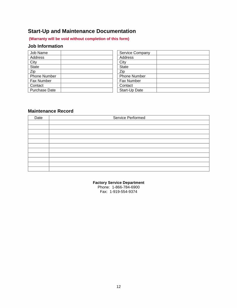
Start-Up and Maintenance Documentation
(Warranty will be void without completion of this form)
Job Information
Job Name Service Company
Address Address
City City
State State
Zip Zip
Phone Number Phone Number
Fax Number Fax Number
Contact Contact
Purchase Date Start-Up Date
Maintenance Record
Date Service Performed
Factory Service Department Phone: 1-866-784-6900
Fax: 1-919-554-9374