Installation and operating instructions -...
16
MG Installation and operating instructions GRUNDFOS INSTRUCTIONS
Transcript of Installation and operating instructions -...

MGInstallation and operating instructions
GRUNDFOS INSTRUCTIONS
En
glis
h (G
B)
English (GB) Installation and operating instructions
Original installation and operating instructions.
CONTENTSPage
1. Symbols used in this document
1.1 Safety
Observe the safety instructions to ensure correct installation, operation and maintenance of the motor. The instructions must be known by any person installing, using or maintaining the motor. Failure to observe the instructions may invalidate the warranty.
Safety equipment required to prevent accidents must be made available according to local safety instructions.
2. IntroductionThese installation and operating instructions apply to these Grundfos MG motors:
For model designation, see section 4.2 Type key.
2.1 Application
MG motors can be used within the framework of IEC 60034.
1. Symbols used in this document 21.1 Safety 2
2. Introduction 22.1 Application 2
3. Delivery and handling 33.1 Delivery 33.2 Handling 3
4. Identification 34.1 Nameplate 34.2 Type key 3
5. Construction 45.1 Mounting designations 45.2 Drain holes 45.3 Motor bearings 45.4 Balancing 45.5 Cable entry/screwed connection 4
6. Operating conditions 56.1 Ambient temperature and installation altitude 56.2 Frequency converter operation 5
7. Mechanical installation 67.1 Clearance 67.2 Terminal box positions 67.3 Outdoor installation 67.4 Foundation 67.5 Alignment 67.6 Fitting of coupling parts and pulleys 6
8. Electrical installation 68.1 General information 68.2 Electrical connection 6
9. Start-up 79.1 Measuring the insulation resistance 79.2 Direction of rotation 7
10. Operation 710.1 Max. number of starts per hour 7
11. Maintenance 711.1 Motor 711.2 Motor bearings 7
12. Technical data 812.1 Weight 812.2 Enclosure class 812.3 Dimensional sketches 812.4 Sound pressure level 812.5 Winding resistances 8
13. Fault finding 8
14. Service 814.1 Motor bearings 814.2 Service documentation 8
15. Disposal 8
Warning
Prior to installation, read these installation and operating instructions. Installation and operation must comply with local regulations and accepted codes of good practice.
Warning
If these safety instructions are not observed, it may result in personal injury.
Warning
If these instructions are not observed, it may lead to electric shock with consequent risk of serious personal injury or death.
Warning
The surface of the product may be so hot that it may cause burns or personal injury.
Caution If these safety instructions are not observed, it may result in malfunction or damage to the equipment.
NoteNotes or instructions that make the job easier and ensure safe operation.
ModelPhase
Power range[kW]
IEC frame size
1 3 2-pole 4-pole 2-pole 4-pole
B 0.25 - 2.2 0.18 - 1.1 71 - 90 71 - 90
0.25 - 71 -
C 0.37 - 11 0.25 - 5.5 71 - 132 71 - 132
D 1.1 - 11 1.1 - 4.0 90 - 160 90 - 112
F 7.5 - 22 5.5 - 15 132 - 180 132 - 160
H 0.75 - 22 0.75 - 15 80 - 180 90 - 160
2

En
gli
sh
(G
B)
3. Delivery and handling3.1 Delivery
Immediately after the receipt, check the motor for external damage. If this is the case, contact the shipping agent immediately. Check whether all nameplate data are according to specifications, especially as regards the voltage and check also whether the winding has been connected correctly according to the wiring diagram in the terminal box cover and the nameplate data.
3.1.1 Unpacking
The motor should not be exposed to unnecessary impact and shocks.
Remove transport protectors, if any. Turn the shaft by hand to check that it rotates freely.
3.2 Handling
3.2.1 Lifting the motor
Lift the motor in the eye bolts. Take care not to damage additional equipment and cables.
The table shows the number of eye bolts and the maximum permissible weight.
Frame sizes 71 and 80 have no eye bolts.
3.2.2 Storage
Until installation, Grundfos motors should be stored in the packaging in which they were delivered.
Store the motors in an enclosed, dry and well-ventilated room. For protection, treat unprotected machine surfaces (shaft ends and flanges) with a corrosion inhibitor.
Storage temperature
-20 °C to +60 °C.
4. Identification
4.1 Nameplate
The motor has two nameplates:
• nameplate with electrical data (50 and 60 Hz)
• nameplate with mechanical data (irrespective of frequency).
The nameplates are positioned on the side of the motor.
4.2 Type key
The type designation is stated on the nameplate.
Caution Do not use sharp tools when unpacking the motor.
Frame size ModelNumber of eye bolts/max. permissible weight
90, 100 B, C, D, H2 x M8/140 kg (1.4 kN)
112, 132 C, D, F, H2 x M10/230 kg (2.3 kN)
160, 180 F, H2 x M12/340 kg (3.4 kN)
Caution
If MG motors are stored, the shaft must be turned by hand at least once a month to prevent it from getting stuck and to distribute the bearing grease.
If the motor has been stored for more than two years before installation, the rotating parts must be dismantled and checked. Relubricate motors with lubricating nipples. Replace the greased-for-life bearings.
Note
Both 50 and 60 Hz data are indicated on the nameplates for three-phase motors.
Only 50 or 60 Hz data are indicated on the nameplates for single-phase motors.
Only 60 Hz data are indicated on previous versions of ML motors.
Example MG 132 S B 2 -38 FF 265 -H 3
Motor Grundfos
Frame size (centre-line height of shaft, foot-mounted motor [mm])
Size, foot:[ ] = frame sizes 71, 80S = smallM = mediumL = large
Length of stator core:ABCD
Number of poles:24
Diameter of shaft end [mm]
Flange version:[ ] = foot-mounted motor, type IM B 3FF = free-hole flangeFT = tapped-hole flange
Pitch circle diameter [mm][ ] = IM B 3
Model:A (discontinued)BCDFH
Efficiency class:[ ] = NA1 = IE2 motor2 = IE1 motor3 = IE3 motor
3

En
glis
h (G
B)
5. Construction
5.1 Mounting designations
5.2 Drain holes
As standard, MG motors have drain holes in the drive end of the stator housing.
If the motor is installed in a humid environment or in areas with high air humidity, open the bottom drain hole. The drain holes enable the escape of water which has entered the stator housing, for instance through condensation.
5.2.1 Number of drain holes
1. The flange can be turned 90 ° and 180 ° to both sides.
2. The flange can be turned 180 °.
3. The flange can be turned 90 ° to both sides.
5.3 Motor bearings
The motor bearing type is stated on the nameplate.
5.3.1 Motors with lubricating nipples
Frame size 160 and 180 motors have lubricating nipples both in the drive end and the non-drive end. The bearings are lubricated from factory and should therefore not be lubricated until commissioning.
The lubricating intervals are stated on the nameplate with mechanical data. For information about lubrication and maintenance of bearings, see section 11.2 Motor bearings.
5.4 Balancing
The rotor is dynamically balanced. As standard, the rotor has been balanced with a half key inserted (cylindrical shaft).
5.5 Cable entry/screwed connection
Motors are supplied without screwed cable entries. The table below shows the number and size of the cable entry holes of the terminal box according to EN 50262.
IEC 60034-7, Code I
IEC 60034-7, Code II
Flange-mounted motor (tapped-hole flange)
IM B 14 IM 3601
IM V 18 IM 3611
Flange-mounted motor (free-hole flange)
IM B 5 IM 3001
IM V 1 IM 3011
Foot-mounted motor
IM B 3 IM 1001
Foot-mounted motor (tapped-hole flange)
IM B 34 IM 2101
Foot-mounted motor (free-hole flange)
IM B 35 IM 2001
Caution If the drain plug is removed, the motor enclosure class will change from IP55 to IP44.
B 3B 14, B 5,B 34, B 35
MG 71, 80
One drain hole closed with a plug1
One drain hole closed with a plug1
MG 90-132
Two drain holes closed with plugs2
Three drain holes closed with plugs2
MG 160, 180
Three drain holes closed with plugs3
Four drain holes closed with plugs3
Frame size
ModelNumber x dimensions
Description
71, 80 B, C, H 2 x (M20 x 1.5)
The holes have precast threads and are closed with knock-out cable entries.
90, 100 B, C, D, H 4 x M20The holes are closed with knock-out cable entries.
112, 132 C, D, F, H 4 x M25
160, 180 F, H4 x M402 x M20
4

En
gli
sh
(G
B)
6. Operating conditions6.1 Ambient temperature and installation altitude
Grundfos motors are designed for operation at temperatures up to 40 °C. Grundfos MG motors are capable of continuous operation at ambient temperatures up to 60 °C, however subject to a shorter bearing life. See section 11.2 Motor bearings.
The ambient temperature and the installation altitude are important factors for the motor life. The table below shows max. ambient temperature and max. installation altitude.
The table does not show combined maximum values, meaning that the motor is not capable of operating at +60 °C at an altitude of 3500 m at the same time.
If these values are exceeded, the motor must not be fully loaded due to the risk of overheating.
Overheating may result from excessive ambient temperatures or low density and consequently low cooling effect of the air.
In such cases, it may be necessary to reduce the load or use a motor with a higher rated output.
The curves below show the maximum motor load of the various efficiency classes.
Fig. 1 Motor output in relation to temperature/installation altitude
Example
The example shows an IE2 motor under these operating conditions:
• Ambient temperature: 65 °C.
• Installation altitude above sea level: 4750 m.
Maximum load of the motor:
• Ambient temperature of 65 °C: 95 %.
• 4750 m above sea level: 88 %.
As both operating conditions apply, the motor must not be loaded more than (0.95 x 0.88) = 83.6 %.
6.2 Frequency converter operation
All three-phase MG motors with phase insulation can be connected to a frequency converter.
6.2.1 Phase insulation
MG 71 and 80
MG motors, frame sizes 71 and 80, do not have phase insulation as standard. The motors are not suitable for frequency converter operation as they are not protected against the voltage peaks caused by frequency converter operation.
Only motors with a rated voltage equal to or above 460 V have phase insulation.
MG 90 to 180
MG motors, frame sizes 90 to 180, have phase insulation. The motors are suitable for frequency converter operation, subject to these precautions:
Operating conditions for MG motors to be used for frequency converter operation
• Supply voltage up to 400 V:
– Check that the motor has phase insulation.(Only motors with a rated voltage equal to or above 460 V have phase insulation.)
• Supply voltage above 400 V:
– Check that the motor has phase insulation.(Only motors with a rated voltage equal to or above 460 V have phase insulation.)
– Fit a sine-wave filter between the motor and the frequency converter.
6.2.2 Acoustic noise and voltage peaks
Frequency converter operation may cause increased acoustic noise from the motor and will often expose the motor insulation system to a heavier load due to voltage peaks reducing motor life. To prevent the voltage peaks from damaging the motor, make sure to observe the limits of IEC 60034-17.
Increased acoustic noise and detrimental voltage peaks can be eliminated by fitting an output filter between the frequency converter and the motor. For further details, contact your frequency converter supplier or Grundfos.
Figure 2 shows the maximum permissible voltage peaks measured at the motor terminals for a specific rise time.
Fig. 2 Maximum values for voltage peaks
Efficiency class
Max. ambient temperature at full
load[°C]
Max. installation altitude above sea
level at full load[m]
NA +40 1000
IE2+60 3500
IE3
TM
05
11
68
23
11
CautionIf the motor load is not reduced in case the ambient temperature or installation altitude is exceeded, the motor life will be limited, and the warranty is void.
P2
100
20t
1000
5060708090
70656055504540353025 8075
475035002250 m
C
%IE3/IE2,MG
Caution Frequency converter operation of MG motors without phase insulation will cause damage to the motor.
TM
04
45
56
17
09
0.0 0.2 0.4 0.6 0.8 1.0 1.2 1.4 1.6t [mS]
800
900
1000
1100
1200
1300
1400
U [V
]
5

En
glis
h (G
B)
How to eliminate problems with noise
• Noise-critical applications:Fit an output filter between the frequency converter and the motor. This will reduce the voltage peaks and consequently the noise.
• Particularly noise-critical applications:Fit a sinusoidal filter. This will reduce the voltage peaks and optimise the sinusoidal wave of the power supply to the motor.
6.2.3 Cable length
The length of the cable between motor and frequency converter affects the motor load. Fit a cable that meets the specifications laid down by the frequency converter supplier.
6.2.4 Speed
Basically, MG motors are not suitable for oversynchronous operation. Contact Grundfos if oversynchronous operation is required.
Oversynchronous operation means that the motor runs at a frequency higher than 60 Hz. This can be achieved by using a frequency converter.
7. Mechanical installationThe installation must be carried out by authorised personnel in accordance with local regulations.
Check by hand that the shaft rotates freely.
7.1 Clearance
To ensure sufficient air circulation, a clearance of minimum 50 mm must be available over/around the motor.
7.2 Terminal box positions
Fig. 3 Permissible terminal box positions
In case of vertically installed motors, the terminal box must not fall more than 10 ° below the horizontal plane.
Make sure that the motor drain holes are positioned so that condensed water can escape from the motor. See section 5.2.1 Number of drain holes.
7.3 Outdoor installation
If it is installed outdoors, protect the motor against water and sunshine.
7.4 Foundation
Grundfos recommends to install motor and pump on a foundation which is heavy enough to provide permanent and rigid support. The foundation must be capable of absorbing any vibration, normal strain or shock.
7.5 Alignment
Correct alignment is important to avoid problems with bearings, vibrations and possible fracture of shaft ends.
7.6 Fitting of coupling parts and pulleys
Fit coupling parts, pulleys and similar components using suitable equipment and tools that do not damage the motor bearings.Never knock a coupling part or pulley into position. Always carry out removal without pressing against the motor.
8. Electrical installation
8.1 General information
Operating voltage and operating frequency are stated on the motor nameplate. Check that the motor is suitable for the power supply available at the installation site.
The voltage quality for MG motors, measured at the motor terminals, must be ± 10 % of the rated voltage during continuous operation (including variation in the supply voltage and losses in cables).
8.1.1 Motor protection
Single-phase motors
Single-phase motors are supplied with built-in thermal protection, according to IEC 60034-11, against thermal overload with both rapid and slow variation.
Three-phase motors
Three-phase motors must be protected by a motor-protective circuit breaker according to local regulations.
MG motors as from 3.0 kW are supplied with thermal switches (PTC) as standard and protected against thermal overload with both rapid and slow variation. The motor protection is stated on the nameplate.
8.2 Electrical connection
The electrical installation should be carried out by authorised personnel in accordance with local regulations.
The wiring diagram is located in the terminal box cover.
The terminal box of single-speed motors normally contains six winding terminals and at least one earth terminal.
8.2.1 Single-phase motor
Connect single-phase motors to the mains in accordance with the instructions located in the terminal box cover.
8.2.2 Three-phase motor
Three-phase motors can be connected in star (Y) or delta (D) according to IEC 60034-8. See the wiring diagram in the terminal box cover.
Voltage and connection are stated on the nameplate.
Example: 380-415 D/660-690 Y
• If the voltage supply is 380-415 V, the motor must be connected in delta.
• If the voltage supply is 660-690 V, the motor must be connected in star.
TM
04
55
10
33
09
Caution Non-compliance may result in functional faults which will damage the motor components.
Warning
Make sure that the power supply cannot be accidentally switched on during the electrical installation.
Warning
The motor must be connected to an external mains switch.
Warning
Whenever motors incorporating a thermal switch or thermistors are to be repaired, make sure that the motor cannot start automatically after cooling.
Warning
Before removing the terminal box cover and before any dismantling of the motor, switch off the power supply.
Warning
The motor must be earthed.
Do not connect the motor to the voltage supply until the connection to earth has been carried out in accordance with local regulations.
6

En
gli
sh
(G
B)
9. Start-up9.1 Measuring the insulation resistance
Measure the insulation resistance before start-up and in case of any risk of moisture in the windings.
Calculate the minimum permissible insulation resistance, R, by multiplying the rated voltage (in kV) of the motor with the constant 0.5 megohm/kV.
Stop using the motor immediately if the insulation resistance falls below this value.
Example
If the rated voltage is 690 V, the measured resistance must be higher than 0.69 kV x 0.5 megohm/kV = 0.35 megohm.
Measure the minimum permissible insulation resistance at a winding temperature of 25 °C (+/- 15 °C).
Procedure:
• Connect the megaohmmeter between phase and earth at a measuring voltage of 500 V DC.
• Read the value on the megaohmmeter.
If the minimum insulation resistance is not attained, the windings are too moist and must be oven-dried.
The oven temperature must be 90 °C for 12-16 hours and then 105 °C for 6-8 hours.
9.2 Direction of rotation
The direction of rotation is clockwise, seen from the motor drive end when the mains conductors are connected in accordance with the diagram located in the terminal box cover. The direction of rotation can be changed by switching two random mains conductors.
10. Operation
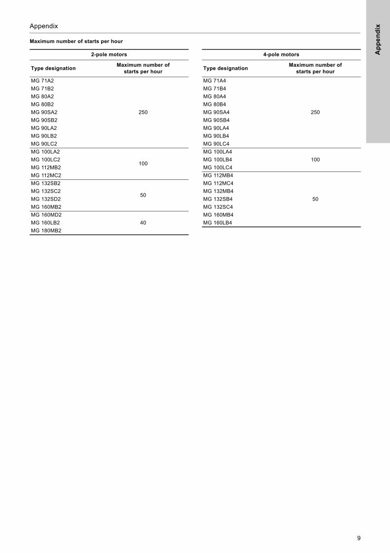
10.1 Max. number of starts per hour
See page 9.
11. Maintenance
11.1 Motor
Inspect the motor at regular intervals, determined by the environment in which the motor is installed. To ensure adequate ventilation, it is important to keep the motor clean. If the motor is installed in a dusty environment, it must be cleaned and checked more often than if it is installed in non-dusty environment.
In standard motors, condensed water cannot escape. The drain hole at the lowest point of the motor can be opened and ensure the escape of water entering the stator housing, for example in connection with condensation.
11.2 Motor bearings
11.2.1 Motors without lubricating nipples
The bearings are greased for life. The expected life is at least 18000 operating hours at an ambient temperature of up to 40 °C. A higher ambient temperature reduces life. A temperature increase of 10 °C reduces life by 50 %.
Bearing grease
The technical specifications of the grease must correspond to DIN 51825, K3N or better.
• 50 cSt (mm2/s) at 40 °C
• 8 cSt (mm2/s) at 100 °C.
Grease filling rate: 30-40 %.
11.2.2 Motors with lubricating nipples
Lubricate the bearings with high-temperature grease as specified on the motor nameplate with mechanical data.
Lubricating intervals are stated on the lubricating plate for 40 °C and 60 °C.We recommend to dismantle the motor when the bearings have been relubricated five times. Clean and check the bearings for damage; replace them if necessary.
In the case of seasonal operation (motor is idle for more than six months of the year), we recommend to lubricate the motor bearings when you take it out of operation.
It is important to relubricate the bearings as specified on the motor nameplate with mechanical data. If this interval is not observed, the bearing life will be reduced.
Reduced lubricating interval
The lubricating interval must be reduced in these situations:
• Dirty and dusty environments. Reduce the lubricating interval by a factor 0.75.
• Very moist environments. Reduce the lubricating interval by a factor 0.9.
If the environments are both dusty and moist, multiply the factors.
Grease type and quantity
See the motor nameplate with mechanical data.
Warning
When measuring the insulation resistance, carefully follow the safety regulations of EN 50110-1 (operation of power plants) and the instruction manual for measuring and test equipment.
Warning
During and immediately after the measurement, there will be a risk of electric shock. Do not touch the terminals until the windings are de-energised.
Note Remove any drain plugs before heating.
Caution Some MG motors have a properly directed fan. The direction of rotation must be as stated on the motor.
Warning
During operation, the motor surface may be so hot that it may cause personal injury.
NoteNever mix grease with thickeners, such as lithium-based grease with polycarbamide-based grease.
7
En
glis
h (G
B)
12. Technical data
12.1 Weight
See nameplate, WinCAPS or WebCAPS.
12.2 Enclosure class
See nameplate, WinCAPS or WebCAPS.
12.3 Dimensional sketches
See page 10.
12.4 Sound pressure level
See WinCAPS or WebCAPS.
12.5 Winding resistances
See WinCAPS, WebCAPS or MG Product Information, PI-052, section "Technical data".
13. Fault finding
The table below covers the most frequent faults. Contact Grundfos if the table does not cover the specific fault.
14. ServiceAll repairs must be carried out in accordance with IEC 60079-19. Observe the provisions of EN 50110-1 until all maintenance work has been completed, and the motor has been assembled.
14.1 Motor bearings
Take care when replacing the motor bearings.
14.2 Service documentation
Service documentation is available on www.grundfos.com > WebCAPS > Service.
If you have any questions, please contact the nearest Grundfos company.
15. DisposalThis product or parts of it must be disposed of in an environmentally sound way:
1. Use the public or private waste collection service.
2. If this is not possible, contact the nearest Grundfos company or service workshop.
Subject to alterations.
Warning
Before starting fault finding, switch off the power supply. Make sure that the power supply cannot be accidentally switched on.
Motor service and fault finding must be carried out by qualified personnel.
Fault Cause
1. Motor does not start. a) Power supply disconnected.
b) Fuses blown.
c) Automatic circuit breakers cut out.
d) Motor-protective circuit breaker tripped.
e) Thermal protection tripped.
f) Contacts of motor-protective circuit breaker or magnet coil defective.
g) Control circuit defective.
h) Blocked rotor.
i) Motor defective.
2. Motor-protective circuit breaker trips immediately when supply is switched on.
a) A fuse blown.
b) Contacts of motor-protective circuit breaker defective.
c) Blocked rotor.
d) Cable connection loose or faulty.
e) Motor winding defective.
f) Motor-protective circuit breaker setting is too low.
3. Motor-protective circuit breaker trips occasionally.
a) Motor-protective circuit breaker setting is too low.
b) Mains voltage periodically too low.
c) Voltage asymmetry
Caution Do not expose the bearings to impacts or shocks.
8
Ap
pe
nd
ix
Appendix 1Maximum number of starts per hour
2-pole motors 4-pole motors
Type designationMaximum number of
starts per hourType designation
Maximum number of starts per hour
MG 71A2
250
MG 71A4
250
MG 71B2 MG 71B4
MG 80A2 MG 80A4
MG 80B2 MG 80B4
MG 90SA2 MG 90SA4
MG 90SB2 MG 90SB4
MG 90LA2 MG 90LA4
MG 90LB2 MG 90LB4
MG 90LC2 MG 90LC4
MG 100LA2
100
MG 100LA4
100MG 100LC2 MG 100LB4
MG 112MB2 MG 100LC4
MG 112MC2 MG 112MB4
50
MG 132SB2
50
MG 112MC4
MG 132SC2 MG 132MB4
MG 132SD2 MG 132SB4
MG 160MB2 MG 132SC4
MG 160MD2
40
MG 160MB4
MG 160LB2 MG 160LB4
MG 180MB2
9

Ap
pe
nd
ix
Dimensional sketches
Fig. 1 Foot-mounted motor, IM B 3
Fig. 2 Foot-mounted motor with free-hole flange, IM B 35Motor with free-hole flange, IM B5/V1
Fig. 3 Foot-mounted motor with tapped-hole flange, IM B 34Motor with tapped-hole flange, IM B14/V18
TM
02
88
00
09
04
EB
D
HA
EB
BA
BB
K
E C B
L
A
H
AB
HC
AA
HD
AD
GA
F
DB
AC
LL
B’
G
O AG
TM
02
88
05
09
04
EB
D
HA
EB
BA
BB
K
B
L
A
HAB
AA
HD
LB
AD
GA
F
DB
AC
T LA
NP
45
SxZ
M
B’
G
OAGLL
HC
E C
TM
02
88
04
09
04
EB
D
HA
EB
BA
BB
K
E
C B
L
A
H
AB
HC
AA
HD
LB
AD
GA
F
DB
AC
B’
G
NP
SxZ
AGLLO
M
45°
T
LA
10

Ap
pe
nd
ix
Dimensions, 2-poleCa
ble
en
try
O
Th
ree-
ph
ase,
2-p
ole
, IE
no
t d
efin
ed (
P2
< 0
.75
kW)
2X
M2
0
2X
M2
0
2X
M2
0
Th
ree
-ph
as
e,
2-p
ole
, IE
3 R
an
ge
2X
M2
0
2X
M2
0
4X
M2
02
)
4X
M2
02
)
4X
M2
02
)
4X
M2
52
)
4X
M2
52
)
4X
M2
52
)
2X
M2
0,
4X
M4
02
)
2X
M2
0,
4X
M4
02
)
2X
M2
0,
4X
M4
02
)
2X
M2
0,
4X
M4
02
)
Th
ree
-ph
as
e,
2-p
ole
, IE
2 R
an
ge
2X
M2
0
4X
M2
02
)
4X
M2
02
)
4X
M2
02
)
4X
M2
52
)
4X
M2
52
)
4X
M2
52
)
2X
M2
0,
4X
M4
02
)
2X
M2
0,
4X
M4
02
)
2X
M2
0,
4X
M4
02
)
2X
M2
0,
4X
M4
02
)
1)
Wh
en
fitt
ing
a c
om
po
ne
nt
on
th
e m
oto
r fla
ng
e,
che
ck t
ha
t th
e t
hro
ug
h-g
oin
g s
cre
ws
do
no
t p
en
etr
ate
de
ep
er
into
th
e f
lan
ge
th
an
th
e d
ime
nsi
on
LA
. If
th
e s
cre
ws
are
to
o lo
ng
, th
ey
can
be
scr
ew
ed
into
th
e s
tato
r w
ind
ing
s.2
) K
no
cko
uts
.
Fo
ot
IM B
3,
IM B
35, I
MB
34
K 7 7 10
10
10
10
10
12
12
12
12
15
15
15
15
10
10
10
12
12
12
12
15
15
15
15
HD
18
0
18
0
18
9
18
9
18
9
20
0
20
0
22
0
24
6
26
6
25
7
32
0
32
0
32
0
34
0
18
9
20
0
20
0
22
0
24
6
26
6
25
7
32
0
32
0
32
0
34
0
HC
14
2
14
2
15
1
15
1
15
1
17
9
17
9
19
9
22
2
24
2
26
2
31
7
31
7
31
7
33
7
15
1
17
9
17
9
19
9
22
2
24
2
26
2
31
7
31
7
31
7
33
7
HA 3 3 3 3 3 3 3 3 4 5 6 8 8 8 8 3 3 3 3 4 5 6 8 8 8 8
H 71
71
80
80
80
90
90
10
0
112
13
2
13
2
16
0
16
0
16
0
18
0
80
90
90
10
0
112
13
2
13
2
16
0
16
0
16
0
18
0
C 45
45
50
50
50
56
56
63
70
89
89
10
8
10
8
10
8
12
1
50
56
56
63
70
89
89
10
8
10
8
10
8
12
1
BB
110
110
12
5
12
5
12
5
15
5
15
0
17
0
17
2
17
2
16
4
23
9
23
9
28
3
30
8
12
5
15
5
15
0
17
0
17
2
17
2
16
4
23
9
23
9
28
3
30
8
BA
20
20
25
25
25 - - - - - - - - - - 25 - - - - - - - - - -
B' - - - - -
12
5
12
5 - - - - - - -
27
9 -
12
5
12
5 - - - - - - -
27
9
B 90
90
10
0
10
0
10
0
10
0
10
0
14
0
14
0
14
0
14
0
21
0
21
0
25
4
24
1
10
0
10
0
10
0
14
0
14
0
14
0
14
0
21
0
21
0
25
4
24
1
AB
13
9
13
9
15
9
15
9
15
9
17
8
17
8
19
9
22
8
25
5
24
4
28
7
28
7
28
7
31
2
15
9
17
8
17
8
19
9
22
8
25
5
24
4
28
7
28
7
28
7
31
2
AA
27
27
37
37
37 - - - - - 42
49
49
49
61
37 - - - - - 42
49
49
49
61
A 112
112
12
5
12
5
12
5
14
0
14
0
16
0
19
0
21
6
21
6
25
4
25
4
25
4
27
9
12
5
14
0
14
0
16
0
19
0
21
6
21
6
25
4
25
4
25
4
27
9
Fla
ng
eIM
B34
, IM
B1
4/V
18
T 2.5
2.5 3 3 3 3 3 3.5
3.5
3.5
3.5 - - - - 3 3 3 3.5
3.5
3.5
3.5 - - - -
S
M6
X4
M6
X4
M6
X4
M6
X4
M6
X4
M8
X4
M8
X4
M8
X4
M8
X4
M1
0X
4
M1
0X
4
- - - -
M6
X4
M8
X4
M8
X4
M8
X4
M8
X4
M1
0X
4
M1
0X
4
- - - -
P 10
5
10
5
12
0
12
0
12
0
13
5
13
5
16
0
16
0
20
0
20
0 - - - -
12
0
13
5
13
5
16
0
16
0
20
0
20
0 - - - -
N 70
70
80
80
80
95
95
110
110
13
0
13
0 - - - - 80
95
95
110
110
13
0
13
0 - - - -
M 85
85
10
0
10
0
10
0
115
115
13
0
13
0
16
5
16
5 - - - -
10
0
115
115
13
0
13
0
16
5
16
5 - - - -
LA
12
1)
12
1)
12
1)
12
1)
12
1)
13
1)
13
1)
14
1)
14
1)
28
1)
43
1)
- - - -
12
1)
13
1)
13
1)
14
1)
14
1)
28
1)
43
1)
- - - -
Fla
ng
eIM
B35
, IM
B5/
V1
T 3.5
3.5
3.5
3.5
3.5
3.5
3.5 4 4 4 4 5 5 5 5 3.5
3.5
3.5 4 4 4 4 5 5 5 5
S
∅1
0X
4
∅1
0X
4
∅1
2X
4
∅1
2X
4
∅1
2X
4
∅1
2X
4
∅1
2X
4
∅1
5X
4
∅1
5X
4
∅1
5X
4
∅1
5X
4
∅1
9X
4
∅1
9X
4
∅1
9X
4
∅1
9X
4
∅1
2X
4
∅1
2X
4
∅1
2X
4
∅1
5X
4
∅1
5X
4
∅1
5X
4
∅1
5X
4
∅1
9X
4
∅1
9X
4
∅1
9X
4
∅1
9X
4
P 16
0
16
0
20
0
20
0
20
0
20
0
20
0
25
0
25
0
30
0
30
0
35
0
35
0
35
0
35
0
20
0
20
0
20
0
25
0
25
0
30
0
30
0
35
0
35
0
35
0
35
0
N 110
110
13
0
13
0
13
0
13
0
13
0
18
0
18
0
23
0
23
0
25
0
25
0
25
0
25
0
13
0
13
0
13
0
18
0
18
0
23
0
23
0
25
0
25
0
25
0
25
0
M 13
0
13
0
16
5
16
5
16
5
16
5
16
5
21
5
21
5
26
5
26
5
30
0
30
0
30
0
30
0
16
5
16
5
16
5
21
5
21
5
26
5
26
5
30
0
30
0
30
0
30
0
LA 10
10
10
10
10
18
18
10
10
12
12
12
12
12
12
10
18
18
10
10
12
12
12
12
12
12
Sh
aft
end
GA
16
16
21
.5
21
.5
21
.5
27
27
31
31
41
41
45
45
45
51
.5
21
.5
27
27
31
31
41
41
45
45
45
51
.5
G 11 11 15
.5
15
.5
15
.5
20
20
24
24
33
33
37
37
37
43
15
.5
20
20
24
24
33
33
37
37
37
43
F 5 5 6 6 6 8 8 8 8 10
10
12
12
12
14 6 8 8 8 8 10
10
12
12
12
14
EB
22
22
32
32
32
40
40
50
50
70
70
82
82
82
10
0
32
40
40
50
50
70
70
82
82
82
10
0
E 30
30
40
40
40
50
50
60
60
80
80
110
110
110
110
40
50
50
60
60
80
80
110
110
110
110
DB
M5
M5
M6
M6
M6
M8
M8
M1
0
M1
0
M1
2
M1
2
M1
6
M1
6
M1
6
M1
6
M6
M8
M8
M1
0
M1
0
M1
2
M1
2
M1
6
M1
6
M1
6
M1
6
D 14
14
19
19
19
24
24
28
28
38
38
42
42
42
48
19
24
24
28
28
38
38
42
42
42
48
Sta
tor
ho
usi
ng
LL
82
82
82
82
82
10
3
10
3
10
3
10
3
10
3
13
5
21
3
21
3
21
3
21
3
82
10
3
10
3
10
3
10
3
10
3
13
5
21
3
21
3
21
3
21
3
LB
19
1
19
1
23
1
23
1
25
1
28
1
32
1
33
5
37
2
39
1
37
9
47
1
47
1
51
5
54
1
23
1
28
1
32
1
33
5
37
2
39
1
37
9
47
1
47
1
51
5
54
1
L
22
1
22
1
27
1
27
1
29
1
33
1
37
1
39
5
43
2
47
1
45
9
58
1
58
1
62
5
65
1
27
1
33
1
37
1
39
5
43
2
47
1
45
9
58
1
58
1
62
5
65
1
AG 82
82
82
82
82
16
2
16
2
16
2
20
2
20
2
20
3
24
3
24
3
24
3
24
3
82
16
2
16
2
16
2
20
2
20
2
20
3
24
3
24
3
24
3
24
3
AD
10
9
10
9
10
9
10
9
10
9
110
110
12
0
13
4
13
4
15
9
20
4
20
4
20
4
20
4
10
9
110
110
12
0
13
4
13
4
15
9
20
4
20
4
20
4
20
4
AC
14
1
14
1
14
1
14
1
14
1
17
8
17
8
19
8
22
0
22
0
26
0
31
4
31
4
31
4
31
4
14
1
17
8
17
8
19
8
22
0
22
0
26
0
31
4
31
4
31
4
31
4
Fra
me
size
MG
71
A2
-C
MG
71
B2
-C
MG
80
A2
-C
MG
80
A2
-H3
MG
80
C2
-H3
MG
90
SB
2-H
3
MG
90
LC
2-H
3
MG
10
0L
C2
-H3
MG
112
MC
2-H
3
MG
13
2S
C2
-H3
MG
13
2S
B2
-H3
MG
16
0M
B2
-H3
MG
16
0M
D2
-H3
MG
16
0L
B2
-H3
MG
18
0M
B2
-H3
MG
80
B2
-D1
MG
90
SB
2-D
1
MG
90
LC
2-D
1
MG
10
0L
C2
-D1
MG
112
MC
2-D
1
MG
13
2S
C2
-D1
MG
13
2S
B2
-F1
MG
16
0M
B2
-F1
MG
16
0M
D2
-F1
MG
16
0L
B2
-F1
MG
18
0M
B2
-F1
11

Ap
pe
nd
ix
Dimensions, 4-pole
Ca
ble
en
try
O
Th
ree
-ph
ase
, 4-p
ole
, IE
no
t d
efin
ed (
P2
< 0
.75
kW
)
2X
M2
0
2X
M2
0
2X
M2
0
2X
M2
0
Th
ree
-ph
as
e,
4-p
ole
, IE
3 R
an
ge
4X
M2
02
)
4X
M2
02
)
4X
M2
02
)
4X
M2
02
)
4X
M2
02
)
4X
M2
52
)
4X
M2
52
)
4X
M2
52
)
2X
M2
0,
4X
M4
02
)
2X
M2
0,
4X
M4
02
)
Th
ree
-ph
as
e,
4-p
ole
, IE
2 R
an
ge
4X
M2
02
)
4X
M2
02
)
4X
M2
02
)
4X
M2
02
)
4X
M2
02
)
4X
M2
52
)
4X
M2
52
)
4X
M2
52
)
2X
M2
0,
4X
M4
02
)
2X
M2
0,
4X
M4
02
)
1)
Wh
en
fitt
ing
a c
om
po
ne
nt
on
th
e m
oto
r fla
ng
e,
che
ck t
ha
t th
e t
hro
ug
h-g
oin
g s
cre
ws
do
no
t p
en
etr
ate
de
ep
er
into
th
e f
lan
ge
th
an
th
e d
ime
nsi
on
LA
. If
th
e s
cre
ws
are
to
o lo
ng
, th
ey
can
be
scr
ew
ed
into
th
e s
tato
r w
ind
ing
s.2
) K
no
cko
uts
.
Fo
ot
IM B
3,
IM B
35, I
MB
34
K 7 7 10
10
10
10
10
12
12
12
12
12
15
15
10
10
10
12
12
12
12
12
15
15
HD
18
0
18
0
18
9
18
9
20
0
20
0
20
0
22
0
22
0
24
6
25
7
25
7
32
0
32
0
20
0
20
0
20
0
22
0
22
0
24
6
25
7
25
7
32
0
32
0
HC
14
2
14
2
15
1
15
1
17
9
17
9
17
9
19
9
19
9
22
2
26
2
26
2
31
7
31
7
17
9
17
9
17
9
19
9
19
9
22
2
26
2
26
2
31
7
31
7
HA 3 3 3 3 3 3 3 3 3 4 6 6 8 8 3 3 3 3 3 4 6 6 8 8
H 71
71
80
80
80
90
90
10
0
10
0
112
13
2
13
2
16
0
16
0
90
90
90
10
0
10
0
112
13
2
13
2
16
0
16
0
C 45
45
50
50
56
56
56
63
63
70
89
89
10
8
10
8
56
56
56
63
63
70
89
89
10
8
10
8
BB
110
110
12
5
12
5
15
5
15
0
15
0
17
0
17
0
17
2
16
4
20
2
28
3
31
3
15
0
15
0
15
0
17
0
17
0
17
2
16
4
20
2
23
9
28
3
BA
20
20
25
25 - - - - - - - - - - - - - - - - - - - -
B' - - - -
12
5
12
5
12
5 - - - -
17
8 - -
12
5
12
5
12
5 - - - -
17
8 - -
B 90
90
10
0
10
0
10
0
10
0
10
0
14
0
14
0
14
0
14
0
14
0
25
4
25
4
10
0
10
0
10
0
14
0
14
0
14
0
14
0
14
0
21
0
25
4
AB
13
9
13
9
15
9
15
9
17
8
17
8
17
8
19
9
19
9
22
8
24
4
24
4
28
7
28
7
17
8
17
8
17
8
19
9
19
9
22
8
24
4
24
4
28
7
28
7
AA
27
27
37
37 - - - - - - 42
42
49
49 - - - - - - 42
42
49
49
A 112
112
12
5
12
5
14
0
14
0
14
0
16
0
16
0
19
0
21
6
21
6
25
4
25
4
14
0
14
0
14
0
16
0
16
0
19
0
21
6
21
6
25
4
25
4
Fla
ng
eIM
B34
, IM
B1
4/V
18
T 2.5
2.5 3 3 3 3 3 3.5
3.5
3.5 - - - - 3 3 3 3.5
3.5
3.5 - - - -
S
M6
X4
M6
X4
M6
X4
M6
X4
M8
X4
M8
X4
M8
X4
M8
X4
M8
X4
M8
X4
- - - -
M6
X4
M8
X4
M8
X4
M8
X4
M8
X4
M8
X4
- - - -
P 10
5
10
5
12
0
12
0
13
5
13
5
13
5
16
0
16
0
16
0 - - - -
12
0
13
5
13
5
16
0
16
0
16
0 - - - -
N 70
70
80
80
95
95
95
110
110
110 - - - - 80
95
95
110
110
110 - - - -
M 85
85
10
0
10
0
115
115
115
13
0
13
0
13
0 - - - -
10
0
115
115
13
0
13
0
13
0 - - - -
LA
12
1)
12
1)
12
1)
12
1)
13
1)
13
1)
13
1)
14
1)
14
1)
14
1)
- - - -
12
1)
13
1)
13
1)
14
1)
14
1)
14
1)
- - - -
Fla
ng
eIM
B35
, IM
B5/
V1
T 3.5
3.5
3.5
3.5
3.5
3.5
3.5 4 4 4 4 4 5 5 3.5
3.5
3.5 4 4 4 4 4 5 5
S
∅1
0X
4
∅1
0X
4
∅1
2X
4
∅1
2X
4
∅1
2X
4
∅1
2X
4
∅1
2X
4
∅1
5X
4
∅1
5X
4
∅1
5X
4
∅1
5X
4
∅1
5X
4
∅1
9X
4
∅1
9X
4
∅1
2X
4
∅1
2X
4
∅1
2X
4
∅1
5X
4
∅1
5X
4
∅1
5X
4
∅1
5X
4
∅1
5X
4
∅1
9X
4
∅1
9X
4
P 16
0
16
0
20
0
20
0
20
0
20
0
20
0
25
0
25
0
25
0
30
0
30
0
35
0
35
0
20
0
20
0
20
0
25
0
25
0
25
0
30
0
30
0
35
0
35
0
N 110
110
13
0
13
0
13
0
13
0
13
0
18
0
18
0
18
0
23
0
23
0
25
0
25
0
13
0
13
0
13
0
18
0
18
0
18
0
23
0
23
0
25
0
25
0
M 13
0
13
0
16
5
16
5
16
5
16
5
16
5
21
5
21
5
21
5
26
5
26
5
30
0
30
0
16
5
16
5
16
5
21
5
21
5
21
5
26
5
26
5
30
0
30
0
LA 10
10
10
10
18
18
18
10
10
10
12
12
12
12
10
18
18
10
10
10
12
12
12
12
Sh
aft
en
d
GA
16
16
21
.5
21
.5
21
.5
27
27
31
31
31
41
41
45
45
21
.5
27
27
31
31
31
41
41
45
45
G 11 11 15
.5
15
.5
15
.5
20
20
24
24
24
33
33
37
37
15
.5
20
20
24
24
24
33
33
37
37
F 5 5 6 6 6 8 8 8 8 8 10
10
12
12 6 8 8 8 8 8 10
10
12
12
EB
22
22
32
32
32
40
40
50
50
50
70
70
82
82
32
40
40
50
50
50
70
70
82
82
E 30
30
40
40
40
50
50
60
60
60
80
80
110
110
40
50
50
60
60
60
80
80
110
110
DB
M5
M5
M6
M6
M6
M8
M8
M1
0
M1
0
M1
0
M1
2
M1
2
M1
6
M1
6
M6
M8
M8
M1
0
M1
0
M1
0
M1
2
M1
2
M1
6
M1
6
D 14
14
19
19
19
24
24
28
28
28
38
38
42
42
19
24
24
28
28
28
38
38
42
42
Sta
tor
ho
usi
ng
LL
82
82
82
82
10
3
10
3
10
3
10
3
10
3
10
3
13
5
13
5
21
3
21
3
82
10
3
10
3
10
3
10
3
10
3
13
5
13
5
21
3
21
3
LB
19
1
19
1
23
1
23
1
28
1
32
1
32
1
33
5
33
5
37
2
37
9
42
9
54
5
57
5
23
1
32
1
32
1
33
5
33
5
37
2
37
9
42
9
47
1
51
5
L
22
1
22
1
27
1
27
1
32
1
37
1
37
1
39
5
39
5
43
2
45
9
50
9
65
5
68
5
27
1
37
1
37
1
39
5
39
5
43
2
45
9
50
9
58
1
62
5
AG 82
82
82
82
16
2
16
2
16
2
16
2
16
2
20
2
20
3
20
3
24
3
24
3
82
16
2
16
2
16
2
16
2
20
2
20
3
20
3
24
3
24
3
AD
10
9
10
9
10
9
10
9
110
110
110
12
0
12
0
13
4
15
9
15
9
20
4
20
4
10
9
110
110
12
0
12
0
13
4
15
9
15
9
20
4
20
4
AC
14
1
14
1
14
1
14
1
17
8
17
8
17
8
19
8
19
8
22
0
26
0
26
0
31
4
31
4
14
1
17
8
17
8
19
8
19
8
22
0
26
0
26
0
31
4
31
4
Fra
me
size
MG
71
A4
-C
MG
71
B4
-C
MG
80
A4
-C
MG
80
B4
-C
MG
90
SC
4-H
3
MG
90
SB
4-H
3
MG
90
LC
4-H
3
MG
10
0L
B4
-H3
MG
10
0L
C4
-H3
MG
112
MC
4-H
3
MG
13
2S
B4
-H3
MG
13
2M
B4
-H3
MG
16
0M
A4
-H3
MG
16
0L
B4
-H3
MG
80
C4
-D1
MG
90
SB
4-D
1
MG
90
LC
4-D
1
MG
10
0L
B4
-D1
MG
10
0L
C4
-D1
MG
112
MC
4-D
1
MG
13
2S
B4
-F1
MG
13
2M
B4
-F1
MG
16
0M
B4
-F1
MG
16
0L
B4
-F1
12
De
cla
rati
on
of
co
nfo
rmit
y
Declaration of conformity 2GB: EU declaration of conformityWe, Grundfos, declare under our sole responsibility that the products MG, ML, to which the declaration below relates, are in conformity with the Council Directives listed below on the approximation of the laws of the EU member states.
BG: Декларация за съответствие на ECНие, фирма Grundfos, заявяваме с пълна отговорност, че продуктите MG, ML, за които се отнася настоящата декларация, отговарят на следните директиви на Съвета за уеднаквяване на правните разпоредби на държавите-членки на EC.
CZ: Prohlášení o shodě EUMy firma Grundfos prohlašujeme na svou plnou odpovědnost, že výrobky MG, ML, na které se toto prohlášení vztahuje, jsou v souladu s níže uvedenými ustanoveními směrnice Rady pro sblížení právních předpisů členských států Evropského společenství.
DE: EU-KonformitätserklärungWir, Grundfos, erklären in alleiniger Verantwortung, dass die Produkte MG, ML, auf die sich diese Erklärung beziehen, mit den folgenden Richtlinien des Rates zur Angleichung der Rechtsvorschriften der EU-Mitgliedsstaaten übereinstimmen.
DK: EU-overensstemmelseserklæringVi, Grundfos, erklærer under ansvar at produkterne MG, ML som erklæringen nedenfor omhandler, er i overensstemmelse med Rådets direktiver der er nævnt nedenfor, om indbyrdes tilnærmelse til EU-medlemsstaternes lovgivning.
EE: EÜvastavusdeklaratsioonMeie, Grundfos, kinnitame ja kanname ainuisikulist vastutust selle eest, et toode MG, ML, mille kohta all olev deklaratsioon käib, on kooskõlas Nõukogu Direktiividega, mis on nimetatud all pool vastavalt vastuvõetud õigusaktidele ühtlustamise kohta EÜ liikmesriikides.
ES: Declaración de conformidad de la UEGrundfos declara, bajo su exclusiva responsabilidad, que los productos MG, ML a los que hace referencia la siguiente declaración cumplen lo establecido por las siguientes Directivas del Consejo sobre la aproximación de las legislaciones de los Estados miembros de la UE.
FI: EU-vaatimustenmukaisuusvakuutusGrundfos vakuuttaa omalla vastuullaan, että tuotteet MG, ML, joita tämä vakuutus koskee, ovat EU:n jäsenvaltioiden lainsäädännön lähentämiseen tähtäävien Euroopan neuvoston direktiivien vaatimusten mukaisia seuraavasti.
FR: Déclaration de conformité UENous, Grundfos, déclarons sous notre seule responsabilité, que les produits MG, ML, auxquels se réfère cette déclaration, sont conformes aux Directives du Conseil concernant le rapprochement des législations des États membres UE relatives aux normes énoncées ci-dessous.
GR: ∆ήλωση συμμόρφωσης ΕΕΕμείς, η Grundfos, δηλώνουμε με αποκλειστικά δική μας ευθύνη ότι τα προϊόντα MG, ML, στα οποία αναφέρεται η παρακάτω δήλωση, συμμορφώνονται με τις παρακάτω Οδηγίες του Συμβουλίου περί προσέγγισης των νομοθεσιών των κρατών μελών της ΕΕ.
HR: EU deklaracija sukladnostiMi, Grundfos, izjavljujemo s punom odgovornošću da su proizvodi MG, ML, na koja se izjava odnosi u nastavku, u skladu s direktivama Vijeća dolje navedene o usklađivanju zakona država članica EU-a.
HU: EU megfelelőségi nyilatkozatMi, a Grundfos vállalat, teljes felelősséggel kijelentjük, hogy a(z) MG, ML termékek, amelyre az alábbi nyilatkozat vonatkozik, megfelelnek az Európai Unió tagállamainak jogi irányelveit összehangoló tanács alábbi előírásainak.
IT: Dichiarazione di conformità UEGrundfos dichiara sotto la sua esclusiva responsabilità che i prodotti MG, ML, ai quale si riferisce questa dichiarazione, sono conformi alle seguenti direttive del Consiglio riguardanti il riavvicinamento delle legislazioni degli Stati membri UE.
LT: ES atitikties deklaracijaMes, Grundfos, su visa atsakomybe pareiškiame, kad produktai MG, ML, kuriems skirta ši deklaracija, atitinka žemiau nurodytas Tarybos Direktyvas dėl ES šalių narių įstatymų suderinimo.
LV: ES atbilstības deklarācijaSabiedrība Grundfos ar pilnu atbildību paziņo, ka produkti MG, ML, uz kuru attiecas tālāk redzamā deklarācija, atbilst tālāk norādītajām Padomes direktīvām par ES dalībvalstu normatīvo aktu tuvināšanu.
NL: EU-conformiteitsverklaringWij, Grundfos, verklaren geheel onder eigen verantwoordelijkheid dat de producten MG, ML, waarop de onderstaande verklaring betrekking heeft, in overeenstemming zijn met de onderstaande Richtlijnen van de Raad inzake de onderlinge aanpassing van de wetgeving van de EU-lidstaten.
PL: Deklaracja zgodności UEMy, Grundfos, oświadczamy z pełną odpowiedzialnością, że nasze produkty MG, ML, których deklaracja niniejsza dotyczy, są zgodne z następującymi dyrektywami Rady w sprawie zbliżenia przepisów prawnych państw członkowskich.
PT: Declaração de conformidade UEA Grundfos declara sob sua única responsabilidade que os produtos MG, ML, aos quais diz respeito a declaração abaixo, estão em conformidade com as Directivas do Conselho sobre a aproximação das legislações dos Estados Membros da UE.
RO: Declaraţia de conformitate UENoi Grundfos declarăm pe propria răspundere că produsele MG, ML, la care se referă această declaraţie, sunt în conformitate cu Directivele de Consiliu specificate mai jos privind armonizarea legilor statelor membre UE.
RS: Deklaracija o usklađenosti EUMi, kompanija Grundfos, izjavljujemo pod punom vlastitom odgovornošću da je proizvod MG, ML, na koji se odnosi deklaracija ispod, u skladu sa dole prikazanim direktivama Saveta za usklađivanje zakona država članica EU.
RU: Декларация о соответствии нормам ЕСМы, компания Grundfos, со всей ответственностью заявляем, что изделия MG, ML, к которым относится нижеприведённая декларация, соответствуют нижеприведённым Директивам Совета Евросоюза о тождественности законов стран-членов ЕС.
SE: EU-försäkran om överensstämmelseVi, Grundfos, försäkrar under ansvar att produkterna MG, ML, som omfattas av nedanstående försäkran, är i överensstämmelse med de rådsdirektiv om inbördes närmande till EU-medlemsstaternas lagstiftning som listas nedan.
SI: Izjava o skladnosti EUV Grundfosu s polno odgovornostjo izjavljamo, da je izdelek MG, ML, na katerega se spodnja izjava nanaša, v skladu s spodnjimi direktivami Sveta o približevanju zakonodaje za izenačevanje pravnih predpisov držav članic EU.
SK: ES vyhlásenie o zhodeMy, spoločnosť Grundfos, vyhlasujeme na svoju plnú zodpovednosť, že produkty MG, ML na ktoré sa vyhlásenie uvedené nižšie vzťahuje, sú v súlade s ustanoveniami nižšie uvedených smerníc Rady pre zblíženie právnych predpisov členských štátov EÚ.
TR: AB uygunluk bildirgesiGrundfos olarak, aşağıdaki bildirim konusu olan MG, ML ürünlerinin, AB Üye ülkelerinin direktiflerinin yakınlaştırılmasıyla ilgili durumun aşağıdaki Konsey Direktifleriyle uyumlu olduğunu ve bununla ilgili olarak tüm sorumluluğun bize ait olduğunu beyan ederiz.
UA: Декларація відповідності директивам EUМи, компанія Grundfos, під нашу одноосібну відповідальність заявляємо, що вироби MG, ML, до яких відноситься нижченаведена декларація, відповідають директивам EU, переліченим нижче, щодо тотожності законів країн-членів ЄС.
CN: 欧盟符合性声明我们,格兰富,在我们的全权责任下声明,产品 MG、ML,即该合格证所指之产品,欧盟使其成员国法律趋于一致的以下理事会指令。
JP: EU 適合宣言Grundfos は、その責任の下に、 MG、ML 製品が EU 加盟諸国の法規に関連する、以下の評議会指令に適合していることを宣言します。
KO: EU 적합성 선언Grundfos 는 아래의 선언과 관련된 MG, ML 제품이 EU 회원국 법률에 기반하여 아래의 이사회 지침을 준수함을 단독 책임 하에 선언합니다 .
BS: Izjava o usklađenosti EUMi, kompanija Grundfos, izjavljujemo pod vlastitom odgovornošću da je proizvod MG, ML, na koji se odnosi izjava ispod, u skladu sa niže prikazanim direktivama Vijeća o usklađivanju zakona država članica EU.
13

De
cla
ratio
n o
f co
nfo
rmity
ID: Deklarasi kesesuaian Uni EropaKami, Grundfos, menyatakan dengan tanggung jawab kami sendiri bahwa produk MG, ML, yang berkaitan dengan pernyataan ini, sesuai dengan Petunjuk Dewan berikut ini serta sedapat mungkin sesuai dengan hukum negara-negara anggota Uni Eropa.
KZ: Сəйкестік жөніндегі ЕО декларациясыБіз, Grundfos, ЕО мүше елдерінің заңдарына жақын төменде көрсетілген Кеңес директиваларына сəйкес төмендегі декларацияға қатысты MG, ML өнімдері біздің жеке жауапкершілігімізде екенін мəлімдейміз.
MK: Декларација за сообразност на ЕУНие, Grundfos, изјавуваме под целосна одговорност дека производите MG, ML, на кои се однесува долунаведената декларација, се во согласност со овие директиви на Советот за приближување на законите на земјите-членки на ЕY.
MY: Perisytiharan keakuran EUKami, Grundfos, mengisytiharkan di bawah tanggungjawab kami semata-mata bahawa produk MG, ML, yang berkaitan dengan perisytiharan di bawah, akur dengan Perintah Majlis yang disenaraikan di bawah ini tentang penghampiran undang-undang negara ahli EU.
NO: EUs samsvarsærklæringVi, Grundfos, erklærer under vårt eneansvar at produktene MG, ML som denne erklæringen gjelder, er i samsvar med styrets direktiver om tilnærming av forordninger i EU-landene.
TH: คําประกาศความสอดคลองตามมาตรฐาน EUเราในนามของบริษัท Grundfos ขอประกาศภายใตความรับผิดชอบของเราแตเพียงผู เดียววาผลิตภัณฑ MG, ML ซึ่งเก่ียวของกับคําประกาศนี้ มีความสอดคลองกับระเบียบคําสั่งตามรายการดานลางนี้ของสภาวิชาชีพวาดวยคาประมาณตามกฎหมายของรัฐท่ีเปนสมาชิก EU
TW: EU 合格聲明葛蘭富根據我們唯一的責任,茲聲明與以下聲明相關之 MG、ML 產品,符合下列近似 EU 會員國法律之議會指令。
VI: Tuyên bố tuân thủ EUChúng tôi, Grundfos, tuyên bố trong phạm vi trách nhiệm duy nhất của mình rằng sản phẩm MG, ML mà tuyên bố dưới đây có liên quan tuân thủ các Chỉ thị Hội đồng sau về việc áp dụng luật pháp của các nước thành viên EU.
AL: Deklara e konformitetit të BENe, Grundfos, deklarojmë vetëm nën përgjegjësinë tonë se produktet MG, ML, me të cilat lidhet kjo deklaratë, janë në pajtueshmëri me direktivat e Këshillit të renditura më poshtë për përafrimin e ligjeve të shteteve anëtare të BE-së.
— Low Voltage Directive (2014/35/EU).Standards used: EN 60334-1:2010
— Ecodesign Directive (2009/125/EC).Electric motors:Commission Regulation No 640/2009.Applies to 50 Hz or 50/60 Hz, three-phase Grundfos motors, in the range of 0.75 - 22 kW and 1.0 to 30 hp, marked IE2 or IE3. See the motor nameplate.Standard used: EN 60034-30:2009.
These motors must not be put into service until the machinery into which they are to be incorporated has been declared in conformity with the relevant directives.This EU declaration of conformity is only valid when published as part of the Grundfos installation and operating instructions (publication number 98079951 0516).
Bjerringbro, 17/3/2016
Zoltán LajtosEngineering Manager
GRUNDFOS Holding A/SPoul Due Jensens Vej 7
8850 Bjerringbro, Denmark
Person authorised to compile the technical file and empowered to sign the EU declaration of conformity.
AR ة رار مطابق EU: إقن أن المنتجي ة ب ؤوليتنا الفردي ى مس دفوس، بمقتض ن، جرون ر نح ،ML وMGنق
ذ س الم ات المجل ابقين لتوجيھ ان مط اه، يكون رار أدن ا اإلق ص بھم ذين يخت ورةالل كة/االتحا ة األوروبي اء المجموع دول أعض وانين ال ن ق ب بي أن التقري اه بش دأدن
ي (EU). األوروب
14

Gru
nd
fos
co
mp
anie
s
ArgentinaBombas GRUNDFOS de Argentina S.A.Ruta Panamericana km. 37.500 Centro Industrial Garin1619 Garín Pcia. de B.A.Phone: +54-3327 414 444Telefax: +54-3327 45 3190
AustraliaGRUNDFOS Pumps Pty. Ltd. P.O. Box 2040 Regency Park South Australia 5942 Phone: +61-8-8461-4611 Telefax: +61-8-8340 0155
AustriaGRUNDFOS Pumpen Vertrieb Ges.m.b.H.Grundfosstraße 2 A-5082 Grödig/Salzburg Tel.: +43-6246-883-0 Telefax: +43-6246-883-30
BelgiumN.V. GRUNDFOS Bellux S.A. Boomsesteenweg 81-83 B-2630 Aartselaar Tél.: +32-3-870 7300 Télécopie: +32-3-870 7301
BelarusПредставительство ГРУНДФОС в Минске220125, Минскул. Шафарнянская, 11, оф. 56, БЦ «Порт»Тел.: +7 (375 17) 286 39 72/73Факс: +7 (375 17) 286 39 71E-mail: [email protected]
Bosna and HerzegovinaGRUNDFOS SarajevoZmaja od Bosne 7-7A,BH-71000 SarajevoPhone: +387 33 592 480Telefax: +387 33 590 465www.ba.grundfos.come-mail: [email protected]
BrazilBOMBAS GRUNDFOS DO BRASILAv. Humberto de Alencar Castelo Branco, 630CEP 09850 - 300São Bernardo do Campo - SPPhone: +55-11 4393 5533Telefax: +55-11 4343 5015
BulgariaGrundfos Bulgaria EOODSlatina DistrictIztochna Tangenta street no. 100BG - 1592 SofiaTel. +359 2 49 22 200Fax. +359 2 49 22 201email: [email protected]
CanadaGRUNDFOS Canada Inc. 2941 Brighton Road Oakville, Ontario L6H 6C9 Phone: +1-905 829 9533 Telefax: +1-905 829 9512
ChinaGRUNDFOS Pumps (Shanghai) Co. Ltd.10F The Hub, No. 33 Suhong RoadMinhang DistrictShanghai 201106PRCPhone: +86 21 612 252 22Telefax: +86 21 612 253 33
CroatiaGRUNDFOS CROATIA d.o.o.Buzinski prilaz 38, BuzinHR-10010 ZagrebPhone: +385 1 6595 400 Telefax: +385 1 6595 499www.hr.grundfos.com
Czech RepublicGRUNDFOS s.r.o.Čajkovského 21779 00 OlomoucPhone: +420-585-716 111Telefax: +420-585-716 299
DenmarkGRUNDFOS DK A/S Martin Bachs Vej 3 DK-8850 Bjerringbro Tlf.: +45-87 50 50 50 Telefax: +45-87 50 51 51 E-mail: [email protected]/DK
EstoniaGRUNDFOS Pumps Eesti OÜPeterburi tee 92G11415 TallinnTel: + 372 606 1690Fax: + 372 606 1691
FinlandOY GRUNDFOS Pumput AB Trukkikuja 1 FI-01360 Vantaa Phone: +358-(0) 207 889 500Telefax: +358-(0) 207 889 550
FrancePompes GRUNDFOS Distribution S.A. Parc d’Activités de Chesnes 57, rue de Malacombe F-38290 St. Quentin Fallavier (Lyon) Tél.: +33-4 74 82 15 15 Télécopie: +33-4 74 94 10 51
GermanyGRUNDFOS GMBHSchlüterstr. 3340699 ErkrathTel.: +49-(0) 211 929 69-0 Telefax: +49-(0) 211 929 69-3799e-mail: [email protected] in Deutschland:e-mail: [email protected]
GreeceGRUNDFOS Hellas A.E.B.E. 20th km. Athinon-Markopoulou Av. P.O. Box 71 GR-19002 Peania Phone: +0030-210-66 83 400 Telefax: +0030-210-66 46 273
Hong KongGRUNDFOS Pumps (Hong Kong) Ltd. Unit 1, Ground floor Siu Wai Industrial Centre 29-33 Wing Hong Street & 68 King Lam Street, Cheung Sha Wan Kowloon Phone: +852-27861706 / 27861741 Telefax: +852-27858664
HungaryGRUNDFOS Hungária Kft.Park u. 8H-2045 Törökbálint, Phone: +36-23 511 110Telefax: +36-23 511 111
IndiaGRUNDFOS Pumps India Private Limited118 Old Mahabalipuram RoadThoraipakkamChennai 600 096Phone: +91-44 2496 6800
IndonesiaPT. GRUNDFOS POMPAGraha Intirub Lt. 2 & 3Jln. Cililitan Besar No.454. Makasar, Jakarta TimurID-Jakarta 13650Phone: +62 21-469-51900Telefax: +62 21-460 6910 / 460 6901
IrelandGRUNDFOS (Ireland) Ltd. Unit A, Merrywell Business ParkBallymount Road LowerDublin 12 Phone: +353-1-4089 800 Telefax: +353-1-4089 830
ItalyGRUNDFOS Pompe Italia S.r.l. Via Gran Sasso 4I-20060 Truccazzano (Milano)Tel.: +39-02-95838112 Telefax: +39-02-95309290 / 95838461
JapanGRUNDFOS Pumps K.K.Gotanda Metalion Bldg., 5F, 5-21-15, Higashi-gotandaShiagawa-ku, Tokyo141-0022 JapanPhone: +81 35 448 1391Telefax: +81 35 448 9619
KoreaGRUNDFOS Pumps Korea Ltd.6th Floor, Aju Building 679-5Yeoksam-dong, Kangnam-ku, 135-916Seoul, KoreaPhone: +82-2-5317 600Telefax: +82-2-5633 725
LatviaSIA GRUNDFOS Pumps Latvia Deglava biznesa centrsAugusta Deglava ielā 60, LV-1035, Rīga,Tālr.: + 371 714 9640, 7 149 641Fakss: + 371 914 9646
LithuaniaGRUNDFOS Pumps UABSmolensko g. 6LT-03201 VilniusTel: + 370 52 395 430Fax: + 370 52 395 431
MalaysiaGRUNDFOS Pumps Sdn. Bhd.7 Jalan Peguam U1/25Glenmarie Industrial Park40150 Shah AlamSelangor Phone: +60-3-5569 2922Telefax: +60-3-5569 2866
MexicoBombas GRUNDFOS de México S.A. de C.V. Boulevard TLC No. 15Parque Industrial Stiva AeropuertoApodaca, N.L. 66600Phone: +52-81-8144 4000 Telefax: +52-81-8144 4010
NetherlandsGRUNDFOS NetherlandsVeluwezoom 351326 AE AlmerePostbus 220151302 CA ALMERE Tel.: +31-88-478 6336 Telefax: +31-88-478 6332E-mail: [email protected]
New ZealandGRUNDFOS Pumps NZ Ltd.17 Beatrice Tinsley CrescentNorth Harbour Industrial EstateAlbany, AucklandPhone: +64-9-415 3240Telefax: +64-9-415 3250
NorwayGRUNDFOS Pumper A/S Strømsveien 344 Postboks 235, Leirdal N-1011 Oslo Tlf.: +47-22 90 47 00 Telefax: +47-22 32 21 50
PolandGRUNDFOS Pompy Sp. z o.o.ul. Klonowa 23Baranowo k. PoznaniaPL-62-081 PrzeźmierowoTel: (+48-61) 650 13 00Fax: (+48-61) 650 13 50
PortugalBombas GRUNDFOS Portugal, S.A. Rua Calvet de Magalhães, 241Apartado 1079P-2770-153 Paço de ArcosTel.: +351-21-440 76 00Telefax: +351-21-440 76 90
RomaniaGRUNDFOS Pompe România SRLBd. Biruintei, nr 103 Pantelimon county IlfovPhone: +40 21 200 4100Telefax: +40 21 200 4101E-mail: [email protected]
RussiaООО Грундфос Россия109544, г. Москва, ул. Школьная, 39-41, стр. 1Тел. (+7) 495 564-88-00 (495) 737-30-00Факс (+7) 495 564 88 11E-mail [email protected]
Serbia Grundfos Srbija d.o.o.Omladinskih brigada 90b11070 Novi Beograd Phone: +381 11 2258 740Telefax: +381 11 2281 769www.rs.grundfos.com
SingaporeGRUNDFOS (Singapore) Pte. Ltd.25 Jalan Tukang Singapore 619264 Phone: +65-6681 9688 Telefax: +65-6681 9689
SlovakiaGRUNDFOS s.r.o.Prievozská 4D 821 09 BRATISLAVA Phona: +421 2 5020 1426sk.grundfos.com
SloveniaGRUNDFOS LJUBLJANA, d.o.o.Leskoškova 9e, 1122 LjubljanaPhone: +386 (0) 1 568 06 10Telefax: +386 (0)1 568 06 19E-mail: [email protected]
South AfricaGRUNDFOS (PTY) LTDCorner Mountjoy and George Allen RoadsWilbart Ext. 2Bedfordview 2008Phone: (+27) 11 579 4800Fax: (+27) 11 455 6066E-mail: [email protected]
SpainBombas GRUNDFOS España S.A. Camino de la Fuentecilla, s/n E-28110 Algete (Madrid) Tel.: +34-91-848 8800 Telefax: +34-91-628 0465
SwedenGRUNDFOS AB Box 333 (Lunnagårdsgatan 6) 431 24 Mölndal Tel.: +46 31 332 23 000Telefax: +46 31 331 94 60
SwitzerlandGRUNDFOS Pumpen AG Bruggacherstrasse 10 CH-8117 Fällanden/ZH Tel.: +41-44-806 8111 Telefax: +41-44-806 8115
TaiwanGRUNDFOS Pumps (Taiwan) Ltd. 7 Floor, 219 Min-Chuan Road Taichung, Taiwan, R.O.C. Phone: +886-4-2305 0868Telefax: +886-4-2305 0878
ThailandGRUNDFOS (Thailand) Ltd. 92 Chaloem Phrakiat Rama 9 Road,Dokmai, Pravej, Bangkok 10250Phone: +66-2-725 8999Telefax: +66-2-725 8998
TurkeyGRUNDFOS POMPA San. ve Tic. Ltd. Sti.Gebze Organize Sanayi Bölgesi Ihsan dede Caddesi,2. yol 200. Sokak No. 20441490 Gebze/ KocaeliPhone: +90 - 262-679 7979Telefax: +90 - 262-679 7905E-mail: [email protected]
UkraineБізнес Центр ЄвропаСтоличне шосе, 103м. Київ, 03131, Україна Телефон: (+38 044) 237 04 00 Факс.: (+38 044) 237 04 01E-mail: [email protected]
United Arab EmiratesGRUNDFOS Gulf DistributionP.O. Box 16768Jebel Ali Free ZoneDubaiPhone: +971 4 8815 166Telefax: +971 4 8815 136
United KingdomGRUNDFOS Pumps Ltd. Grovebury Road Leighton Buzzard/Beds. LU7 4TL Phone: +44-1525-850000 Telefax: +44-1525-850011
U.S.A.GRUNDFOS Pumps Corporation 17100 West 118th TerraceOlathe, Kansas 66061Phone: +1-913-227-3400 Telefax: +1-913-227-3500
UzbekistanGrundfos Tashkent, Uzbekistan The Representative Office of Grundfos Kazakhstan in Uzbekistan38a, Oybek street, TashkentТелефон: (+998) 71 150 3290 / 71 150 3291Факс: (+998) 71 150 3292
Addresses Revised 25.01.2016
98079951 0516
ECM: 1183957 The
nam
e G
rund
fos,
the
Gru
ndfo
s lo
go, a
nd b
e t
hin
k i
nn
ov
ate
are
regi
ster
ed tr
adem
arks
ow
ned
by G
rund
fos
Hol
ding
A/S
or G
rund
fos
A/S,
Den
mar
k. A
ll rig
hts
rese
rved
wor
ldw
ide.
© C
opyr
ight
Gru
ndfo
s H
oldi
ng A
/S
www.grundfos.com