Inserire anche immagine ponteggio - meccad.net · Using the standard CAD design engine ensures...
15
-
Upload
truongthuy -
Category
Documents
-
view
214 -
download
0
Transcript of Inserire anche immagine ponteggio - meccad.net · Using the standard CAD design engine ensures...

Using the standard CAD design engine ensures that:
there is no limitation in drawing schemes and managing the project
thanks to DWG open format, there is a complete integration with other software.
MEC CAD is authorized developer for Autodesk e Bricsys.
We are a company that is oriented to customer satisfaction.
Training: all our software are always provided with a starting training course (e-learning platform
and online courses with a qualified technician); moreover, MEC CAD provides on site courses (at
our headquarters or at the customer).
Technical support: the assistance, timely and available all the
working days, is supplied either by telephone or by using the most
modern and free remote support tools (Skype, TeamViewer).
Customizations: on request MEC CAD develops customizations for
clients.
Updates: MEC CAD constantly updates and improves its products with regards to users’ needs,
always pursuing enhancement and automatization.
MEC CAD is a Software House specialized in the production of software for CAD, which targets
industrial, scaffolding rental companies, construction enterprises, design studios and
entertainment companies. MEC CAD activity is focused on creating programs to support
commercial and technical departments.
The specialization area of MEC CAD is to find technical computer solutions to CAD design of
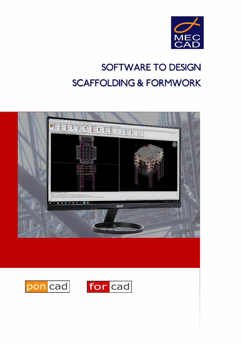
Scaffolding and Formworks. With its SW SUITE made up of PON CAD 3D scaffolding, FOR CAD
formworks for walls and slabs, MEC CAD is one of the main leaders in the development of
software solutions for the industrial application of construction equipment.
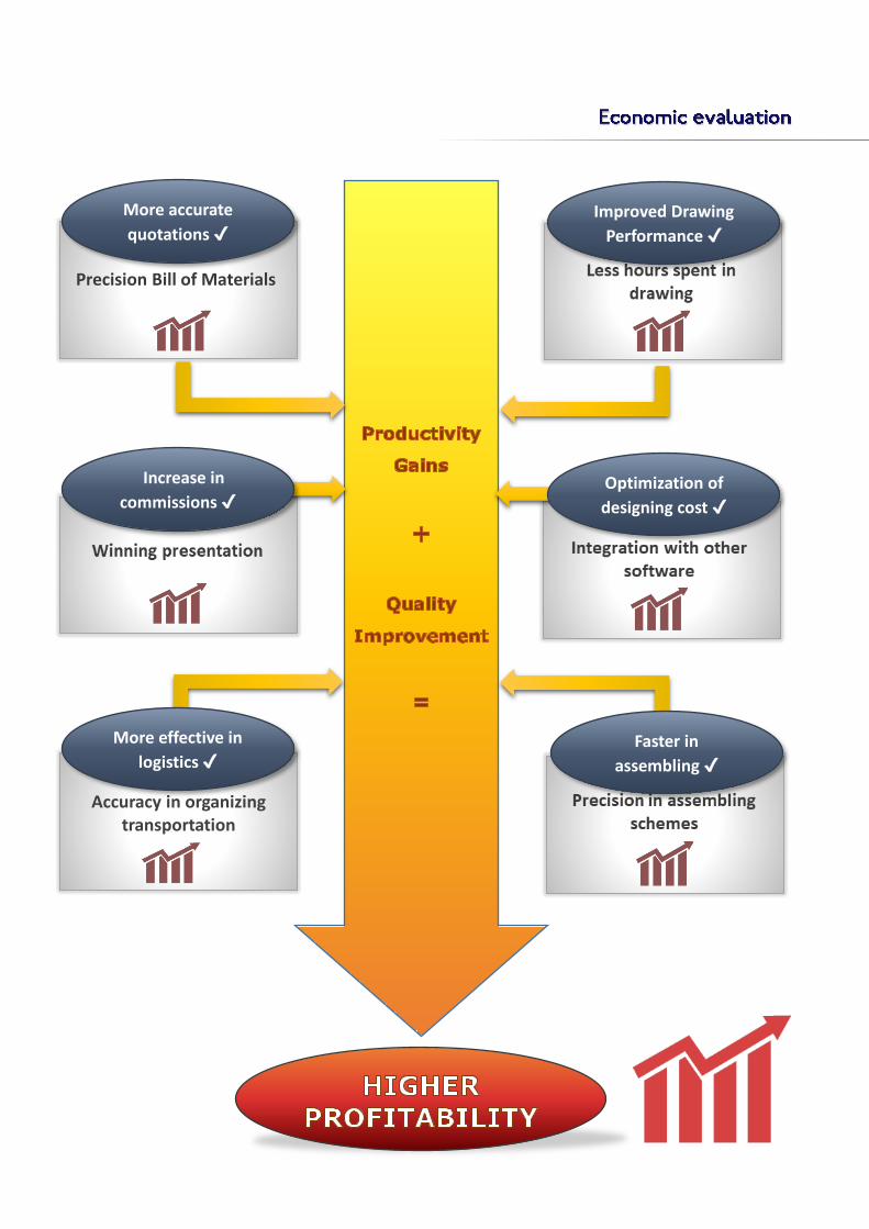
Precision Bill of Materials
Accuracy in organizing transportation
More accurate
quotations ✔
Improved Drawing
Performance ✔
More effective in
logistics ✔
Increase in
commissions ✔ Optimization of
designing cost ✔
Faster in
assembling ✔
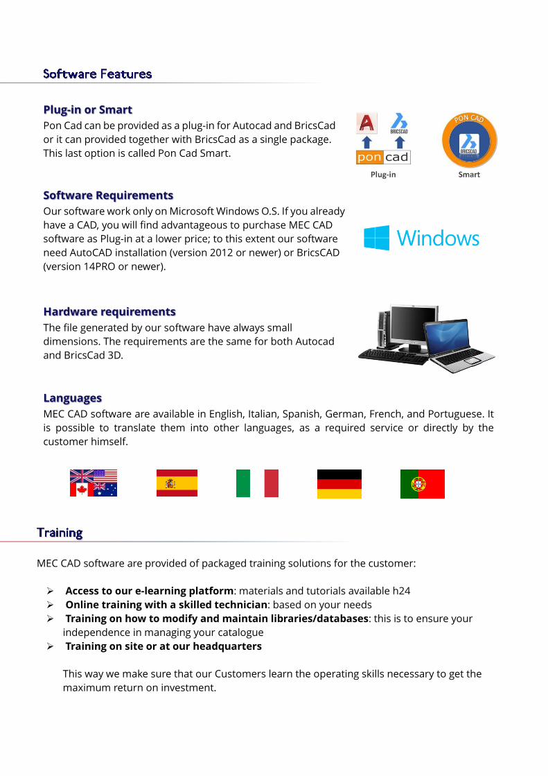
Plug-in or Smart
Pon Cad can be provided as a plug-in for Autocad and BricsCad
or it can provided together with BricsCad as a single package.
This last option is called Pon Cad Smart.
Software Requirements
Our software work only on Microsoft Windows O.S. If you already
have a CAD, you will find advantageous to purchase MEC CAD
software as Plug-in at a lower price; to this extent our software
need AutoCAD installation (version 2012 or newer) or BricsCAD
(version 14PRO or newer).
Hardware requirements
The file generated by our software have always small
dimensions. The requirements are the same for both Autocad
and BricsCad 3D.
Languages
MEC CAD software are available in English, Italian, Spanish, German, French, and Portuguese. It
is possible to translate them into other languages, as a required service or directly by the
customer himself.
MEC CAD software are provided of packaged training solutions for the customer:
Access to our e-learning platform: materials and tutorials available h24
Online training with a skilled technician: based on your needs
Training on how to modify and maintain libraries/databases: this is to ensure your
independence in managing your catalogue
Training on site or at our headquarters
This way we make sure that our Customers learn the operating skills necessary to get the
maximum return on investment.

MEC CAD software use open standard formats only, this ensures that any customer can process
them independently.
This way, the whole MEC CAD Suite can be integrated with other software and makes it easier the
interactions with other stakeholders as well as guarantees data’s availability in the course of time,
regardless of using MEC CAD Suite. In other words it is a guarantee to your investment.
Costumers
Partners
Suppliers
Offers management
Warehouse
management
DMS management
Rendering/Videos
Virtual tour
Dynamic PDFs
Structural analysis
BIM
Inventor
Cloud
Interaction with
other stakeholders
Open Formats
DWG – CSV - TXT – XML –
HTML - IFC
Complete integration
with other software
Data durability
(library/catalogues,
projects, etc.)
MEC CAD software works in BIM!
The software MEC CAD has integrated the exporting into BIM software through the IFC format thanks
to its combination with BricsCAD BIM.
BIM is used in the architectural design of large or prestigious medium-sized buildings, often required
as a mandatory tool; in Europe (CEE), the mandatory use of BIM is becoming increasingly strict. The
activation of this option will bring obvious advantages in the exchange of data between designers,
customers and companies.
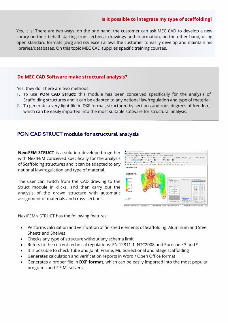
NextFEM STRUCT is a solution developed together
with NextFEM conceived specifically for the analysis
of Scaffolding structures and it can be adapted to any
national law/regulation and type of material.
The user can switch from the CAD drawing to the
Struct module in clicks, and then carry out the
analysis of the drawn structure with automatic
assignment of materials and cross-sections.
NextFEM's STRUCT has the following features:
Performs calculation and verification of finished elements of Scaffolding, Aluminum and Steel
Sheets and Shelves
Checks any type of structure without any schema limit
Refers to the current technical regulations: EN 12811-1, NTC2008 and Eurocode 3 and 9
It is possible to check Tube and Joint, Frame, Multidirectional and Stage scaffolding
Generates calculation and verification reports in Word / Open Office format
Generates a proper file in DXF format, which can be easily imported into the most popular
programs and F.E.M. solvers.
Do MEC CAD Software make structural analysis? Yes, they do! There are two methods:
1. To use PON CAD Struct: this module has been conceived specifically for the analysis of
Scaffolding structures and it can be adapted to any national law/regulation and type of material;
2. To generate a very light file in DXF format, structured by sections and rods degrees of freedom,
which can be easily imported into the most suitable software for structural analysis.
Is it possible to integrate my type of scaffolding?
Yes, it is! There are two ways: on the one hand, the customer can ask MEC CAD to develop a new
library on their behalf starting from technical drawings and information; on the other hand, using
open standard formats (dwg and csv excel) allows the customer to easily develop and maintain his
libraries/databases. On this topic MEC CAD supplies specific training courses.

What is PON CAD?
PON CAD® is a professional tool which supports designers and allows them to easily design and
manage scaffolding, stages, covers and stands, with no limitations on design complexity.
Thanks to its flexibility our software is able to meet any user ’s need and comply with any law that
regulates scaffolding projects, hence being independent from local regulations.
Adding to the CAD 3D more than 200 commands, PON CAD offers an integrated solution for the
phases of:
Design
Costs estimation
Building site management
Multidirectional system (Ringlock)
Frame system
Tube and Fitting
Kwikstage
Cuplock
PON CAD is a parametric software that can design any
scaffolding type, brand and model. 40 libraries/catalogues,
either generic or proprietary, are available, ready to use.
It is supplied with a basic library equipment. User may add
other libraries, already developed by MEC CAD for the main
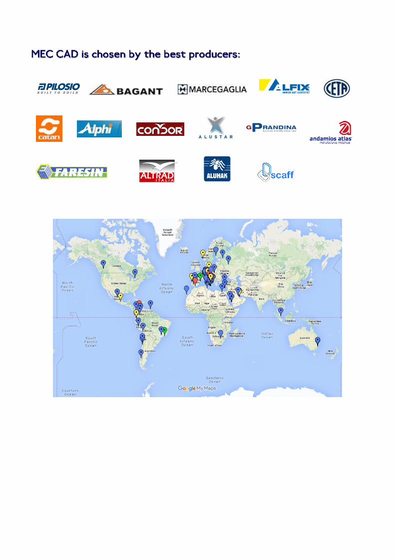
scaffolding manufacturers (Catari,
Marcegaglia, Pilosio, Alustar...).

1. Open your plan
With PON CAD it is possible to draw
starting from a plan or from a
conveniently elaborated image.
PON CAD works in a dwg standard
environment; supported CADs are
AutoCAD and BricsCAD. All their
commands can be used together with
PON CAD ones.
2. Develop 2D modules
The designer can easily create
volumetric modules of complex
scaffolding, by tracing the plan or the
image, solids and existing projects
drawing. Every time it is possible to
move and rotate them, and to change
the specifics (height, starting point,
scaffolding parameters, etc.).
3. Develop scaffolding
After finding the optimal solution,
thanks to a simple command the
designer can determine every feature
of the scaffolding and develop it in the
most detailed way.
After scaffolding development, it is
possible to change and integrate any
particular by using both original CAD
commands and PON CAD commands.

4. Bills of materials
PON CAD creates precise bills of
materials and provides accurate reports
which are useful to manage warehouse,
transportation and construction site, in
short to organize the work in phases.
Bills of materials are produced in open
standard formats: text, word, excel,
(also open office), csv and html which can
be easily integrated with other software.
5. Layout
All technical records (general drafts,
sections, assembling schemes) can be
created in few clicks thanks to powerful
commands.
It is possible to determine sections, views
and details for assembling schemes.
6. Rendering/Video
PON CAD supports different levels of
graphic detail. This allows to easily
create commercial reports and
presentations and facilitates commercial
promotion and technical comprehension.
All above-mentioned features are saved in
pure dwg; therefore everything is
available for more modifications with
other software (BIM or rendering
software).


What is FOR CAD?
FOR CAD® for vertical and horizontal formworks (slabs) is a professional tool which helps designers
to easily design and manage formworks, with no limitations on design complexity.
Adding more than 180 commands to the CAD 3D, FOR CAD suits the needs of the project and of
the designer who is allowed to work in both 2D and 3D mode. This way, FOR CAD offers an
integrated solution for the phases of:
Design
Cost estimation
Material management
Supported formworks brands FOR CAD is a parametric software that can
design any type, brand and model of
vertical and horizontal modular formwork.
It is supplied with a generic library equipment; user may
add other catalogue/libraries, already developed by MEC
CAD for the main formworks manufacturers.
Managing materials phases FOR CAD main strength is to allow a full planning of formworks.
The software offers an integrated and effective solution to manage working phases. Thus, it is
possible to plan, while designing, the complex optimization of materials’ reuse and rotation.
Working in 2D and 3D environment
FOR CAD works in 2D and 3D mode and it is easy to switch from one to the other. This choice is
aimed at optimizing the technical productivity and management of the site logistics. 2D mode is
optimal for the executive design; 3D is ideal for Bills of Material and evaluating assembling
schemes.

1. Open your plan
With FOR CAD it is possible to draw
starting by tracing the plan or the
image, solids and existing projects
drawing.
FOR CAD works in a dwg standard
environment; supported CADs are
AutoCAD and BricsCAD. All their
commands can be used together with
FOR CAD ones.
2. Develop formworks 3D
Thanks to a simple command the
designer can determine every feature
of the formwork and develop it in the
most detailed way.
The development may be
conditioned to warehouse assets
availability or the already
determined phases.
It is always possible to change and
integrate any particular.
3. Bills of Materials FOR CAD creates precise bills of
materials and provides accurate
reports which are useful to manage
warehouse, transportation and
construction site.
It is possible to create BoMs that
highlight the difference of material
by planning in phases.
They are produced in open standard
formats, which can be easily integrated
with other software.

4. Layout
All technical records (general drafts,
sections, assembling schemes) can be
created in few clicks thanks to powerful
commands.
It is possible to determine sections,
views and details for assembling
schemes.
5. From 3D to 2D and viceversa
With a simple click it is possible to
easily switch from 3D mode, ideal for
Bills of Materials and presentations, to
2D one, ideal for working drawings.
Similarly, it is possible the opposite
switching, from 2D to 3D.
6. 2D working drawing
FOR CAD allows to draw up accurate 2D
working drawings in few, simple steps.
Starting from the plan it is possible to
automatically create frontal and
lateral prospects.
2D mode ensures maximum
productivity for working drawings.