

Inserat IRS GmbH - VIVIS · Application of CMT technology for weld cladding..... 353 5. Weld...
24
Inserat IRS GmbH
Transcript of Inserat IRS GmbH - VIVIS · Application of CMT technology for weld cladding..... 353 5. Weld...
341
Technical level of Cladding – Latest Developments –
Technical level of Cladding – Latest Developments –
Wolfgang Hoffmeister and Arne Manzke
1. Introductions .....................................................................................................342
2. Historical development of weld cladding ......................................................342
3. Description of the weld cladding method .....................................................343
3.1. Prerequisites for optimum weld cladding surface ........................................343
3.2. Quality assurance measures .............................................................................344
3.3. Influence of welding wire, shielding gas and welding position ..................345
3.4. The build-up of layers .......................................................................................346
3.4.1. Single-layer weld cladding ...............................................................................3463.4.2. Single-layer/double-layer weld cladding ........................................................3473.4.3. Double-layer weld cladding .............................................................................348
4. Innovations in welding technology – CMT – a revolution in joining technology ..................................................................349
4.1. Development of CMT technology ..................................................................349
4.2. Description of the CMT welding technology method .................................349
4.3. The CMT process compared to other processes ...........................................350
4.4. Application of CMT technology for weld cladding ......................................353
5. Weld cladding with a layer thickness of 1 mm – an alternative to flame spraying? .............................................................................................353
5.1. Flame spraying ..................................................................................................353
5.2. Weld cladding with 1 mm layer thickness .....................................................354
6. Latest constructional designs ..........................................................................355
6.1. Constructional design of outwards bends .....................................................355
6.2. Constructional design for seals in weld-clad areas.......................................356
Wolfgang Hoffmeister, Arne Manzke
342
7. Assembly variants for weld-clad components ...............................................357
8. Proper handling of clad components .............................................................360
9. Summary ............................................................................................................361
10. Literature ............................................................................................................362
1. IntroductionsAs is well known, thermal utilisation of waste in waste incinerators, biofuel and alterna-tive fuel plants causes corrosion on the material qualities traditionally used, e.g. 16Mo3, P265GH, 13CrMo45, etc. In particular at high material temperatures, the elements chlo-rine and sulphur which are released in the flue gas cause extreme emaciation as a result of high-temperature chlorine corrosion and molten salt corrosion. The restricting of flue gas temperatures, the flue gas composition and the operating method can help minimise corrosion mechanisms. However, this makes it impossible to increase the level of efficiency and thus improve electricity production and at the same time it does not make for a clear reduction of damage. It is therefore imperative to take measures on the material side. As well as other measures, the method of weld cladding has emerged – this method makes it possible to increase corrosion resistance whilst still utilising the benefits (strength, welda-bility, formability and price) of traditional steel materials. The following chapters describe different individual weld cladding methods and constructional options, and the specific advantages and disadvantages are explained.
2. Historical development of weld claddingThe problem of corrosion and erosion in waste incineration plants has existed ever since we have been building and operating waste incineration plants.
Before the introduction of waste separation and the tightened conditions of 17. BImSchV the materials used for heating surfaces (St35.8, 16Mo3, 13CrMo45, and 10CrMo9 10) were able to achieve the required service life times taking into account corrosion additions.
The increased plastic content in waste and the associated increase in the heating value, coupled with the higher required temperature level as per 17. BImSchV, have meant that, in areas of waste incineration plants which are exposed to corrosion, the original materials (St35.8, 16Mo3, 13CrMo45, and 10CrMo9 10) are no longer sufficient for the required service life times. The shorter service lives have led to a considerable outlay for cleaning. This has affected both old and new plants.
As early as the 1970s in the USA this problem was being tackled by weld-cladding areas subjected to corrosion with 2.4831 material – also known under the sales name Therma-nit 625. This method, in conjunction with the filler material, had proven very successful although there was no information available on the composition of the waste, the heating value or other stress criteria.
In Germany initial attempts to protect heating surfaces from corrosion using build-up welding were made in 1993. At the Burgkirchen waste incineration plant a test area of weld
343
Technical level of Cladding – Latest Developments –
cladding using Thermanit 625 (1 m²) was installed in the vaporiser above the refractory lining. After 8,000 operating hours no corrosion (emaciation) could be identified. This provided proof that corrosion was controllable using build-up welding.
Test areas in the superheater sections at the waste incineration plants in Mannheim, Lud-wigshafen, Frankfurt and at AVR Rotterdam have achieved the same results. [1]
As a result of these major successes, from the mid-90s, weld-cladding heating surfaces were used for repairs in existing plants. By the start of the new millennium weld cladding was already being included as a preventive measures against corrosion in the planning of new plants. The ratio of weld-clad surfaces for new constructions to weld-clad surfaces for existing plants was approximately 80/20.
3. Description of the weld cladding methodDie word English word cladding, meaning sheathing or jacketing, is used internationally in the specialist world to describe build-up welding using secondary materials on top of base materials, such as boiler tubes made of P235 GH, 16Mo3, 13CrMo45 or 10CrMo45. Weld cladding is performed using a MIG/MAG welding method and automatic, semi-automatic or manual torch guidance. MAG welding rectifiers with programme control and pulsing facilities are used as the welding systems. When cladding tube-fin walls, the welding torches are guided by automatic machine (pedal machine). Individual tubes are weld-clad on lathe machines.CMT (cold metal transfer) welding machines have become more and more established. The advantages are described in a separate chapter 2.4831 material, also known under the sales name Thermanit 625 or Inconel 625, has become established as the filler material. Reference values: C < 0.03 %, Mo 9 %, Nb 3.5 %, Cr 22 %, Fe < 1 % and Ni (rest).Other filler materials, such as 686 or 622, are also used. A 4-component gas is used as a shielding gas, e.g. Cronigon Ni10, formerly known as Cronigon He 30 S. (He 30 %, H2 2 %, CO2 0.055 %, and Ar (rest)).Weld cladding is performed in the welding positions PG (vertical downwards progression) predominantly for cladding tube-fin walls, PE (overhead), e.g. re-cladding on the construc-tion site, PC (horizontal) cladding tubes and walls. The thickness of the layer of weld cladding is generally 2.0 mm. High-grade cladding surfaces have a maximum iron content of 3 %.
3.1. Prerequisites for optimum weld cladding surfaceAn optimum, high-quality weld cladding surface is achieved with the following measures:• Doubleblastcleaningofthesurfaces:FirstblastingprocessasperDIN25410witha
cleanliness level of Sa 2.5 and a surface roughness of 40 – 65 µm. Second blasting process with glass granulate in order to achieve a surface roughness of 35 µm.
With regard to the iron content, welding spatter and even layer thicknesses, you must strive to grind the tube surface on both individual tubes and membrane walls. This method is already applied at Uhlig Rohrbogen GmbH.
• Thewallthicknessesofthecomponentsmustbeatleast≥2.5mm.Areaswithawallthickness of < 2.5 mm are not permitted if not otherwise specified in the order.
• Afterblastingandremovalofthefinedustonthesurface,aprotectiveanti-corrosionpaint (suitable for welding over) must be applied to the surface of the tube to prevent rust bloom.
Wolfgang Hoffmeister, Arne Manzke
344
• Withautomaticweldingtheboilertubeshavetobecooledontheinsidewithcirculatingwater. The water temperature must not exceed 30 °C. The cooling water temperature has a direct influence on the iron dilution on the weld cladding surface (see table 1).
Table 1: Influence of cooling water temperature on dilution
Cr Mo Ni Fe
approx. 20 °C 21 – 21.6 9.7 – 10.2 62.6 – 65 0.1 – 2.1
40 – 60 °C 20.2 – 21.1 9.4 – 10.1 60.4 – 62.9 3.1 – 3.3
100 °C 18.0 – 20.5 9.0 – 9.8 58.0 – 62.7 4.4 – 16.4
Source: Spiegel, M.: Werkstoffe für das Auftragsschweißen für den Korrosionsschutz bei Hochtemperatur-Korrosionsbeanspru-chung. 8. Dresdner Korrosionsschutztage, 24.-25. Oktober 2007
Manual welding can be performed with or without (minimum repair work only) water cooling. In the process the procedure and welding sequence plan must be adhered to.• Beforehand a partitioning specification (e.g. over-partitioning 80.6 mm instead of
80 mm) is set out in order to compensate for shrinkage as a result of weld cladding. The advantage is an exact fit for the partitioning of the walls after weld cladding.
• TheThermanit625fillermaterialisonlyorderedfromthemanufacturerwithanalysisrestriction, i.e. Fe content < 0.2 %, minimisation Si and N content, maximisation Cr, Ni, Mo content.
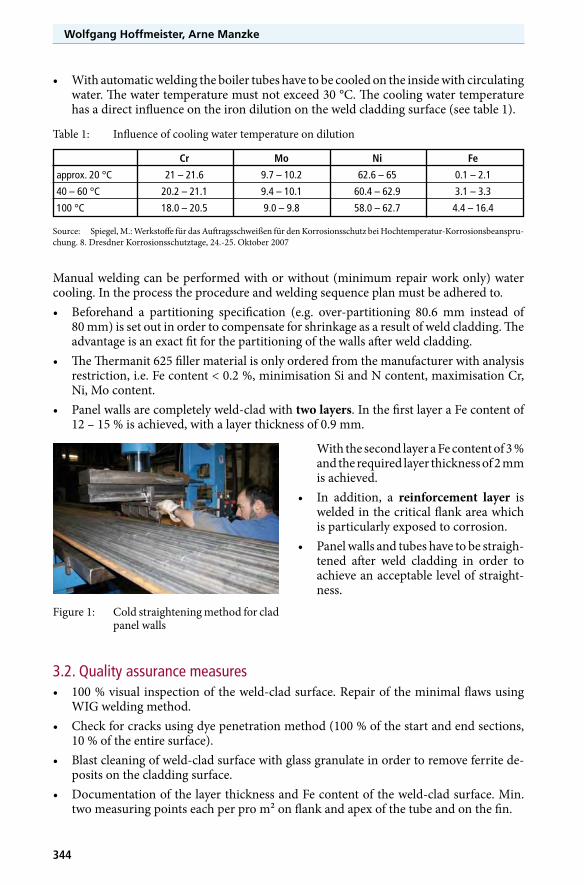
• Panelwallsarecompletelyweld-cladwithtwo layers. In the first layer a Fe content of 12 – 15 % is achieved, with a layer thickness of 0.9 mm.
Figure 1: Cold straightening method for clad panel walls
With the second layer a Fe content of 3 % and the required layer thickness of 2 mm is achieved.
• In addition, a reinforcement layer is welded in the critical flank area which is particularly exposed to corrosion.
• Panelwallsandtubeshavetobestraigh-tened after weld cladding in order to achieve an acceptable level of straight-ness.
3.2. Quality assurance measures• 100%visualinspectionoftheweld-cladsurface.Repairoftheminimalflawsusing
WIG welding method.• Checkforcracksusingdyepenetrationmethod(100%ofthestartandendsections,
10 % of the entire surface).• Blastcleaningofweld-cladsurfacewithglassgranulateinordertoremoveferritede-
posits on the cladding surface.• DocumentationofthelayerthicknessandFecontentoftheweld-cladsurface.Min.
two measuring points each per pro m² on flank and apex of the tube and on the fin.
345
Technical level of Cladding – Latest Developments –
3.3. Influence of welding wire, shielding gas and welding positionAs well as the requirements for the filler material with regard to corrosion and erosion re-sistance, various factors are responsible for the welding properties of the cladding material and thus for the quality of the cladding surface. Influencing variables include the surface quality, torsion, deflection and chemical compo-sition of the selected cladding material.With regard to the surface quality a distinction is made between• abrightfinishand• amattfinish.Matt-drawn wires have a higher strength and a greater surface roughness Drawing com-pound residue builds up in these micro-recesses. This makes for better delivery perfor-mance, especially with long hose packages. However, in this case you have to make sure that the drawing compound residue does not have a negative effect on the welding process and thus the welding results.On bright-drawn wires the drawing compound residue adheres to the welding wire. Com-plete removal of the drawing compound residue is possible but may lead to a poorer wire delivery performance. [3]The torsion and deflection (not on barrels) of the wire have an influence on the resistance in the nozzle area and thus influence the welding results. I.e. if the torsion is greater, the resistance in the nozzle area is lower, which leads to better welding results. Greater torsion is achieved by using barrels in which the cladding material is coiled.The welding performance can also be set analytically by fine-adjusting some alloy elements and restricting certain impurities. [3] As a major consumer of cladding materials, Uhlig is in a position to obtain cladding materials with analysis restrictions. Elements with a positive influence on quality are maximised. At the same time, unfavourable elements are minimised. Uhlig processes cladding materials with a Fe content of much less than 1 %.Beyond the influencing properties of the cladding materials, the shielding gas has a consi-derable influence on the quality of the clad-weld surface. A few years ago Ni-based alloys were still being welded in an inert atmosphere. Argon or an argon / helium mixture were used as shielding gas. (MIG). However, this has the disadvantage of a coarse and scaly joint pattern, a poor connection of layers and the generation of elevated joints.Active components, e.g. CO2 (MAG), quickly cause metal oxidation in the welding arc and have a negative effect on the suitability for welding over of the layers due to the formation of oxide layers, especially with Ni-based alloys. [4]
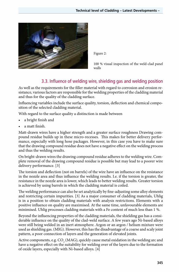
Figure 2:
100 % visual inspection of the weld-clad panel walls
Wolfgang Hoffmeister, Arne Manzke
346
New shielding gasses have been developed especially for welding Ni-based alloys. The ne-gative properties which are generated in an inert atmosphere have been compensated for by adding an active components. Cronigon Ni 10 is a proven shielding gas and comprises the following components: Ar + 0.05 % CO2 + 30 % He + 2 % H2
The effect of the individual components has to be defined as follows:Ar: Base gasCO2: Active components are used to stabilise the welding arc. With Ni materials generally
no surface treatment is performed to ensure corrosion resistance after welding. Excessively thick oxide layers, caused by higher active components (O2, CO2) can cause susceptibility to corrosion in critical situations. The suitability for welding over of layers is increased considerably for multiple-layer welding by the lower level of oxidation.
He: The positive preheating effect facilitates optimum wetting performance.H2: Constriction of the welding arc and heat transfer facilitate forced positions and quick
welding. [4]As well as the above factors, the welding position is also decisive for the quality of the weld cladding surface. When weld cladding was in its infancy, it was predominantly performed in the PA position (flat). Disadvantage: Slow welding speed, high level of dilution of the base material and thus a higher Fe content on the weld cladding surface. Uhlig therefore welds in the PG position (vertical downwards progression). This achieves a higher welding speed and, at the same time, less dilution of the base material. This makes for a lower Fe content on the weld cladding surface which represents an important quality criterion.
3.4. The build-up of layersCurrently a distinction is made between three different geometries for the build-up of layers• Single-layerwith50%overlap(figure3/4).• Single-layer/double-layer(dualweldingtorchinverticalposition)(figure6/7).• Double-layer/double-layer(dualweldingtorch in horizontal position) (figure 8/9).
3.4.1. Single-layer weld cladding
3
7
2
4 9
65
11
10
1
8
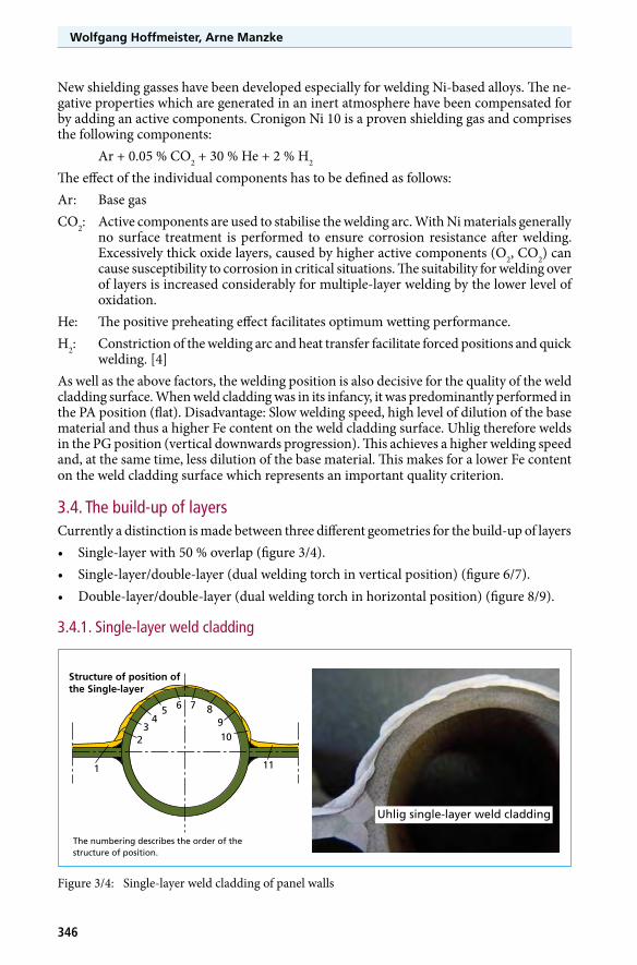
Structure of position of the Single-layer
The numbering describes the order of the structure of position.
Uhlig single-layer weld cladding
Figure 3/4: Single-layer weld cladding of panel walls
347
Technical level of Cladding – Latest Developments –
Single-layer welding uses one welding torch. With this method the programming of the welding machine is always a compromise solution because during the welding process there is a constant alternation between dissi-milar (ferritic-austenitic) and similar (ferritic-ferritic) welding. The individual layers overlap by a minimum of 50 %. In order to achieve the required layer thickness of 2.0 mm, welding has to be performed at a slow welding speed and with a high current level. Consequently there is a high content of iron on the surface. If the overlapping of the individual layers is less than 50 %, it is to be expected that the thickness of the layers will drop below the required level (see figure 5).
The area of vulnerability on the flanks of the welded joints is also very large. In case of faults in the cladding layer which reach through to the base material, corrosion is possible due to the missing second protective layer.
3.4.2. Single-layer/double-layer weld cladding
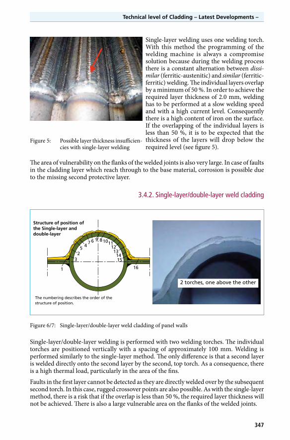
Figure 5: Possible layer thickness insufficien-cies with single-layer welding
Figure 6/7: Single-layer/double-layer weld cladding of panel walls
Single-layer/double-layer welding is performed with two welding torches. The individual torches are positioned vertically with a spacing of approximately 100 mm. Welding is performed similarly to the single-layer method. The only difference is that a second layer is welded directly onto the second layer by the second, top torch. As a consequence, there is a high thermal load, particularly in the area of the fins.
Faults in the first layer cannot be detected as they are directly welded over by the subsequent second torch. In this case, rugged crossover points are also possible. As with the single-layer method, there is a risk that if the overlap is less than 50 %, the required layer thickness will not be achieved. There is also a large vulnerable area on the flanks of the welded joints.
3
7
2
496
1251110
13
161
8
1415
Structure of position of the Single-layer anddouble-layer
The numbering describes the order of the structure of position.
2 torches, one above the other
Wolfgang Hoffmeister, Arne Manzke
348
3.4.3. Double-layer weld cladding
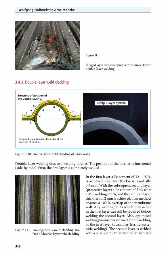
Figure 8:
Rugged layer crossover points from single-layer/double-layer welding
Figure 9/10: Double-layer weld cladding of panel walls
Double-layer welding uses two welding torches. The position of the torches is horizontal (side-by-side). First, the first layer is completely welded.
37
2
4
9
6
12
5
11
10 3
11
8
2
Structure of position of the Double-layer
The numbering describes the order of the structure of position.
Uhlig 2-layer system
Figure 11: Homogeneous weld cladding sur-face of double-layer weld cladding
In the first layer a Fe content of 12 – 15 % is achieved. The layer thickness is initially 0.9 mm. With the subsequent second layer (protective layer) a Fe content of 5 %, with CMT welding < 3 %, and the required layer thickness of 2 mm is achieved. This method ensures a 100 % overlap of the membrane wall. Any welding faults which may occur in the first layer can still be repaired before welding the second layer. Also, optimised welding parameters are used for the welding of the first layer (dissimilar ferritic-auste-nitic welding). The second layer is welded with a purely similar (austenitic-austenitic)
349
Technical level of Cladding – Latest Developments –
welding joint and is also welded with optimised parameters. The thermal load on the mem-brane wall is also lower, which makes for less shrinkage.
4. Innovations in welding technology – CMT – a revolution in joining technology
CMT is a Fronius GmbH development. The abbreviation stands for cold metal transfer.
It is a short welding arc process with a completely new method for spatter removal.
The transfer of material with this welding method is performed relatively cold, compared with the conventional MSG process.
4.1. Development of CMT technologyThe core team comprised 21 developers and was provided with intensive support from a further 15 developers and employees from materials management, the tool shop and production.
The development investment for the CMT series equipment was 39 man-years.
21 patents were submitted to secure property rights.
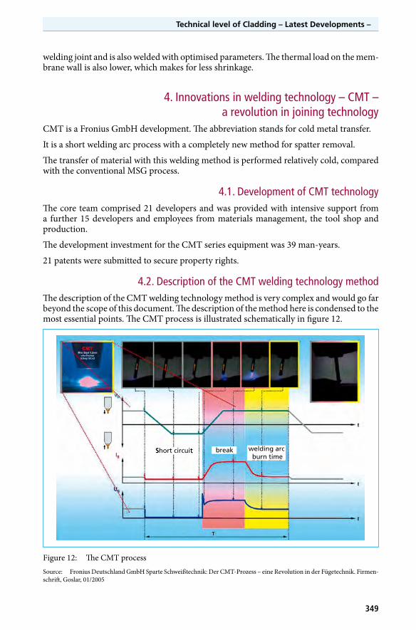
4.2. Description of the CMT welding technology methodThe description of the CMT welding technology method is very complex and would go far beyond the scope of this document. The description of the method here is condensed to the most essential points. The CMT process is illustrated schematically in figure 12.
Short circuit break welding arc bum time
Short circuit break welding arc burn time
Figure 12: The CMT processSource: Fronius Deutschland GmbH Sparte Schweißtechnik: Der CMT-Prozess – eine Revolution in der Fügetechnik. Firmen-schrift, Goslar, 01/2005
Wolfgang Hoffmeister, Arne Manzke
350
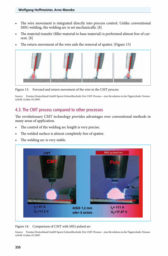
• Thewiremovement is integrateddirectly intoprocesscontrol.UnlikeconventionalMSG welding, the welding arc is set mechanically. [8]
• Thematerialtransfer(fillermaterialtobasematerial)isperformedalmostfreeofcur-rent. [8]
• Thereturnmovementofthewireaidstheremovalofspatter.(Figure13)
Figure 13: Forward and return movement of the wire in the CMT process
Source: Fronius Deutschland GmbH Sparte Schweißtechnik: Der CMT-Prozess – eine Revolution in der Fügetechnik. Firmen-schrift, Goslar, 01/2005
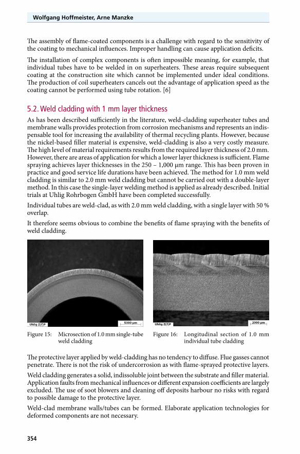
4.3. The CMT process compared to other processesThe revolutionary CMT technology provides advantages over conventional methods in many areas of application.
• Thecontroloftheweldingarclengthisveryprecise.
• Theweldedsurfaceisalmostcompletelyfreeofspatter.
• Theweldingarcisverystable.
Figure 14: Comparison of CMT with MIG pulsed arcSource: Fronius Deutschland GmbH Sparte Schweißtechnik: Der CMT-Prozess – eine Revolution in der Fügetechnik. Firmen-schrift, Goslar, 01/2005

353
Technical level of Cladding – Latest Developments –
• Thelowlevelofheattransfertothecomponentsmeansthatwarpingisupto45%lessthan with the conventional MSG method.
• Lowlevelofweakeningintheheataffectedzone.• Controlledheattransfer.[8]
4.4. Application of CMT technology for weld claddingThe CMT welding technology described above makes for ideal application options for weld cladding. The advantages demonstrated in chapter 4.2. are transferable. The welded surface is almost completely free of spatter. The joint pattern is very regular and the heat transfer to the panel wall is very low.
Alongside the low level of tension in the component, high welding speed and even layer thickness of the weld cladding, a notable benefit is the much lower level of dilution of the base material. It makes for a reduction of at least 50 % of the iron content on the weld cladding surface.
At Uhlig Rohrbogen GmbH they have been using CMT technology successfully since mid-2007 and have converted their entire capacity to CMT.
5. Weld cladding with a layer thickness of 1 mm – an alternative to flame spraying?
In times of rising operating costs and falling prices for waste, operators of thermal recyc-ling plants now strive more than ever to increase the availability of their plants, minimise maintenance and repair costs and improve efficiency. As described at the beginning, this aim is being achieved, e.g. by weld-cladding areas which are exposed to corrosion. Ano-ther alternative secondary measure which has established itself, particularly for reasons of economy, is flame spraying.
5.1. Flame sprayingThe flame spraying method can essentially be described as the application of a metallic material to the substrate in powdered or wire form using a gun. The gun generates a torch gas flame or plasma jet. The powder melts when fed and is applied to the base material being coated by the kinetic energy of the flame, thus forming the desired protective layer. [5]
The layer thicknesses range from 250 to 1,000 µm depending on the method. The flame spraying method does not cause a fusion bond between the coating material and the base material but rather a purely mechanical join. Accordingly, the substrate for coating has to be pre-treated carefully. This can be ideally implemented with workshop applications. There is no dilution of the base material and thus no change to the structure of the base material. [6]
At the same time this is perhaps the biggest advantage as the applied layer has a certain porosity. Flue gasses can diffuse through the protective layer and thus cause undercorro-sion. Methods, e.g. subsequent thermal treatment, can reduce the tendency to diffuse. [7]
With flame spraying there is an almost unlimited number of coating materials. The low increase in mass of the substrate because of the low layer thicknesses is an essential benefit which means lower costs compared to weld cladding with a 2 mm layer thickness. Expe-riences with coating superheaters have been positive whereas the results when thermally spraying membrane walls have not been satisfactory because of the geometry. [6]
Wolfgang Hoffmeister, Arne Manzke
354
The assembly of flame-coated components is a challenge with regard to the sensitivity of the coating to mechanical influences. Improper handling can cause application deficits.
The installation of complex components is often impossible meaning, for example, that individual tubes have to be welded in on superheaters. These areas require subsequent coating at the construction site which cannot be implemented under ideal conditions. The production of coil superheaters cancels out the advantage of application speed as the coating cannot be performed using tube rotation. [6]
5.2. Weld cladding with 1 mm layer thicknessAs has been described sufficiently in the literature, weld-cladding superheater tubes and membrane walls provides protection from corrosion mechanisms and represents an indis-pensable tool for increasing the availability of thermal recycling plants. However, because the nickel-based filler material is expensive, weld-cladding is also a very costly measure. The high level of material requirements results from the required layer thickness of 2.0 mm. However, there are areas of application for which a lower layer thickness is sufficient. Flame spraying achieves layer thicknesses in the 250 – 1,000 µm range. This has been proven in practice and good service life durations have been achieved. The method for 1.0 mm weld cladding is similar to 2.0 mm weld cladding but cannot be carried out with a double-layer method. In this case the single-layer welding method is applied as already described. Initial trials at Uhlig Rohrbogen GmbH have been completed successfully.Individual tubes are weld-clad, as with 2.0 mm weld cladding, with a single layer with 50 % overlap.It therefore seems obvious to combine the benefits of flame spraying with the benefits of weld cladding.
The protective layer applied by weld-cladding has no tendency to diffuse. Flue gasses cannot penetrate. There is not the risk of undercorrosion as with flame-sprayed protective layers.Weld cladding generates a solid, indissoluble joint between the substrate and filler material. Application faults from mechanical influences or different expansion coefficients are largely excluded. The use of soot blowers and cleaning off deposits harbour no risks with regard to possible damage to the protective layer.Weld-clad membrane walls/tubes can be formed. Elaborate application technologies for deformed components are not necessary.
Figure 15: Microsection of 1.0 mm single-tube weld cladding
Figure 16: Longitudinal section of 1.0 mm individual tube cladding
355
Technical level of Cladding – Latest Developments –
The weld cladding can be performed right up to the end of the component. No ferritic ends have to be left free for installation. Costly re-cladding work, which is mostly of reduced quality, are kept to a minimum or eradicated completely.
The increase in weight of the substrates is only approximately 10% greater more than with flame-sprayed base materials with a layer thickness of 1000 µm. The reduction of the layer thickness from 2.0 mm to 1.0 mm thus facilitates a considerable reduction of production costs. The costs for weld cladding a tube with a diameter of 38 mm stand at € 650/m² in this example (November 2011).
6. Latest constructional designsThis chapter demonstrates constructional designs for bent-out tubes and seals. Particular focus is on areas which can be protected by weld cladding.
Today’s technical options are often not known. As a results, out-of-date constructions are often regarded as the standard without any critical analysis.
The consequences can be serious, in particular when medium-carrying components are exposed to corrosion without protection as a result of antiquated standards, which in turn can lead to plant downtimes.
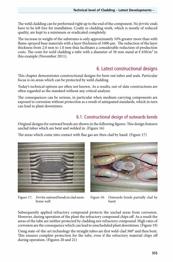
6.1. Constructional design of outwards bendsOriginal designs for outward bends are shown in the following figures. This design features unclad tubes which are bent and welded in. (Figure 16)
The areas which come into contact with flue gas are then clad by hand. (Figure 17)
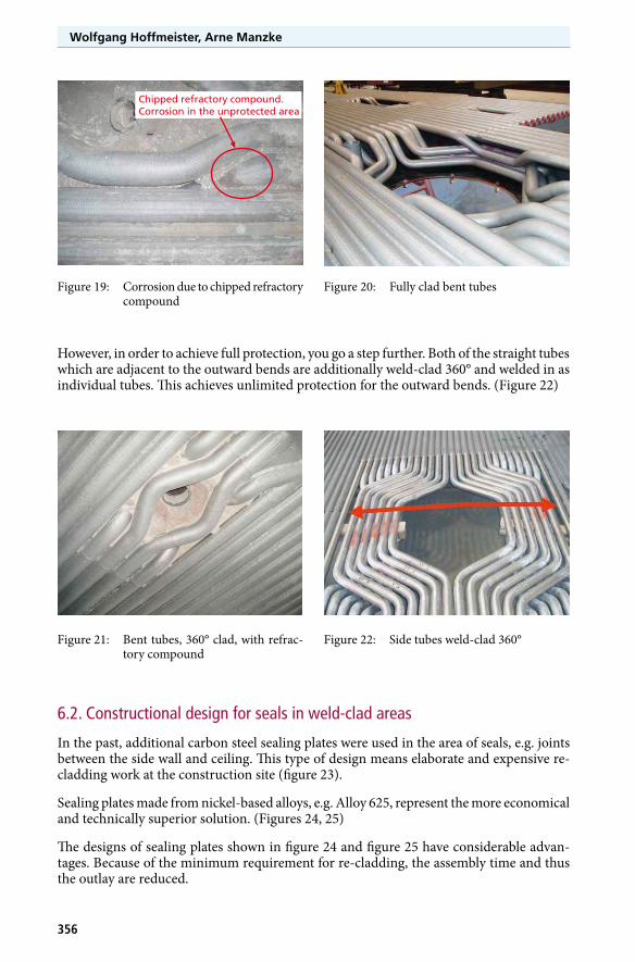
Subsequently applied refractory compound protects the unclad areas from corrosion. However, during operation of the plant the refractory compound chips off. As a result the areas of the tube are neither protected by cladding nor refractory compound. High rates of corrosion are the consequence which can lead to unscheduled plant downtimes. (Figure 19)Using state-of-the-art technology the straight tubes are first weld-clad 360° and then bent. This ensures complete protection for the tube, even if the refractory material chips off during operation. (Figures 20 and 21)
Figure 17: Ferritic outward bends in clad mem-brane wall
Figure 18: Outwards bends partially clad by hand
Wolfgang Hoffmeister, Arne Manzke
356
However, in order to achieve full protection, you go a step further. Both of the straight tubes which are adjacent to the outward bends are additionally weld-clad 360° and welded in as individual tubes. This achieves unlimited protection for the outward bends. (Figure 22)
Figure 19: Corrosion due to chipped refractory compound
Figure 20: Fully clad bent tubes
Figure 21: Bent tubes, 360° clad, with refrac-tory compound
Figure 22: Side tubes weld-clad 360°
Chipped refractory compound.Corrosion in the unprotected area
6.2. Constructional design for seals in weld-clad areas
In the past, additional carbon steel sealing plates were used in the area of seals, e.g. joints between the side wall and ceiling. This type of design means elaborate and expensive re-cladding work at the construction site (figure 23).
Sealing plates made from nickel-based alloys, e.g. Alloy 625, represent the more economical and technically superior solution. (Figures 24, 25)
The designs of sealing plates shown in figure 24 and figure 25 have considerable advan-tages. Because of the minimum requirement for re-cladding, the assembly time and thus the outlay are reduced.

357
Technical level of Cladding – Latest Developments –
Figure 23: Sealing, original design Figure 24: Sealing plates made from Alloy 625
Figure 25:
Weld-clad side wall with Alloy 625 sealing plates
7. Assembly variants for weld-clad components
Examples of assembly variants
The following examples illustrate the different assembly variants are and how they can be best processed.
Wolfgang Hoffmeister, Arne Manzke
358
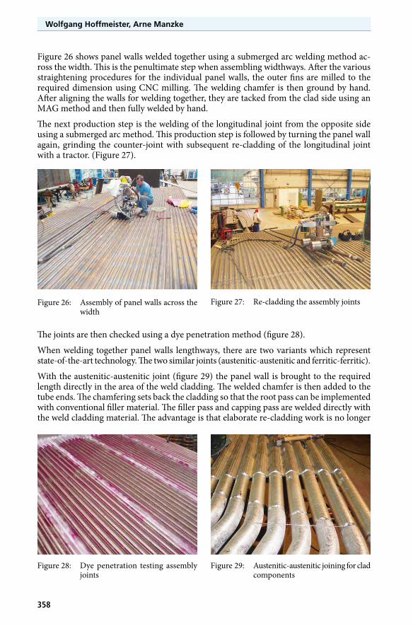
Figure 26 shows panel walls welded together using a submerged arc welding method ac-ross the width. This is the penultimate step when assembling widthways. After the various straightening procedures for the individual panel walls, the outer fins are milled to the required dimension using CNC milling. The welding chamfer is then ground by hand. After aligning the walls for welding together, they are tacked from the clad side using an MAG method and then fully welded by hand.
The next production step is the welding of the longitudinal joint from the opposite side using a submerged arc method. This production step is followed by turning the panel wall again, grinding the counter-joint with subsequent re-cladding of the longitudinal joint with a tractor. (Figure 27).
The joints are then checked using a dye penetration method (figure 28).
When welding together panel walls lengthways, there are two variants which represent state-of-the-art technology. The two similar joints (austenitic-austenitic and ferritic-ferritic).
With the austenitic-austenitic joint (figure 29) the panel wall is brought to the required length directly in the area of the weld cladding. The welded chamfer is then added to the tube ends. The chamfering sets back the cladding so that the root pass can be implemented with conventional filler material. The filler pass and capping pass are welded directly with the weld cladding material. The advantage is that elaborate re-cladding work is no longer
Figure 26: Assembly of panel walls across the width
Figure 27: Re-cladding the assembly joints
Figure 29: Austenitic-austenitic joining for clad components
Figure 28: Dye penetration testing assembly joints
359
Technical level of Cladding – Latest Developments –
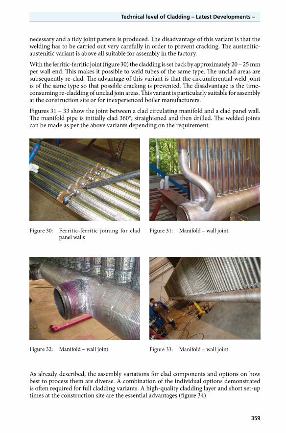
necessary and a tidy joint pattern is produced. The disadvantage of this variant is that the welding has to be carried out very carefully in order to prevent cracking. The austenitic-austenitic variant is above all suitable for assembly in the factory.
With the ferritic-ferritic joint (figure 30) the cladding is set back by approximately 20 – 25 mm per wall end. This makes it possible to weld tubes of the same type. The unclad areas are subsequently re-clad. The advantage of this variant is that the circumferential weld joint is of the same type so that possible cracking is prevented. The disadvantage is the time-consuming re-cladding of unclad join areas. This variant is particularly suitable for assembly at the construction site or for inexperienced boiler manufacturers.
Figures 31 – 33 show the joint between a clad circulating manifold and a clad panel wall. The manifold pipe is initially clad 360°, straightened and then drilled. The welded joints can be made as per the above variants depending on the requirement.
Figure 30: Ferritic-ferritic joining for clad panel walls
Figure 31: Manifold – wall joint
Figure 32: Manifold – wall joint Figure 33: Manifold – wall joint
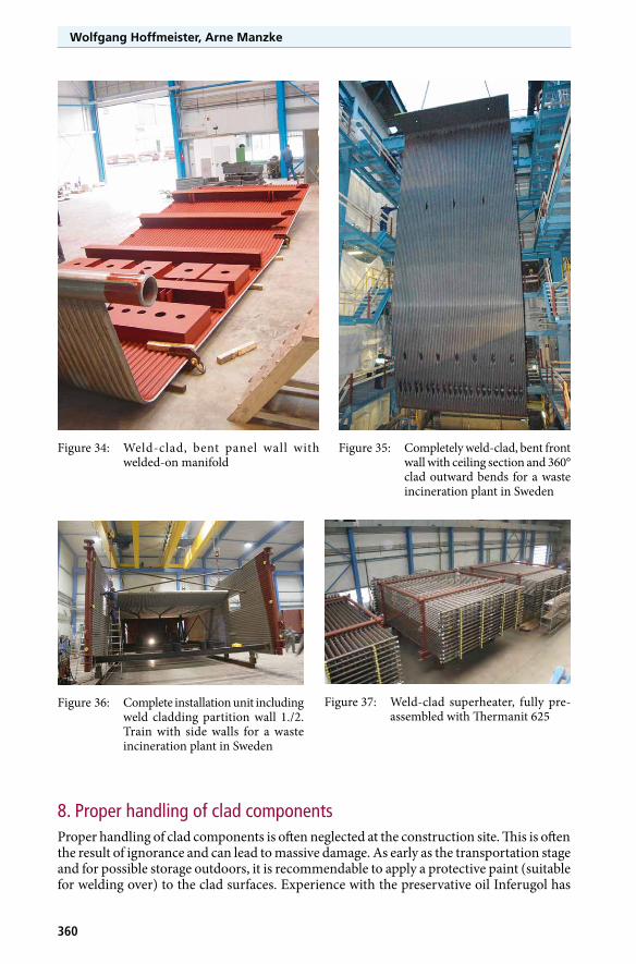
As already described, the assembly variations for clad components and options on how best to process them are diverse. A combination of the individual options demonstrated is often required for full cladding variants. A high-quality cladding layer and short set-up times at the construction site are the essential advantages (figure 34).
Wolfgang Hoffmeister, Arne Manzke
360
Figure 34: Weld-clad, bent panel wall with welded-on manifold
Figure 35: Completely weld-clad, bent front wall with ceiling section and 360° clad outward bends for a waste incineration plant in Sweden
Figure 36: Complete installation unit including weld cladding partition wall 1./2. Train with side walls for a waste incineration plant in Sweden
Figure 37: Weld-clad superheater, fully pre-assembled with Thermanit 625
8. Proper handling of clad componentsProper handling of clad components is often neglected at the construction site. This is often the result of ignorance and can lead to massive damage. As early as the transportation stage and for possible storage outdoors, it is recommendable to apply a protective paint (suitable for welding over) to the clad surfaces. Experience with the preservative oil Inferugol has
361
Technical level of Cladding – Latest Developments –
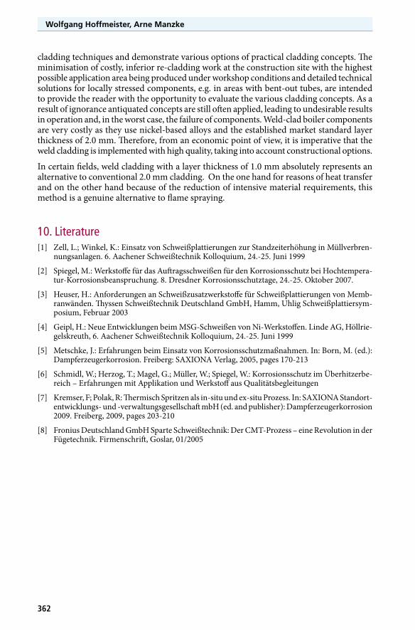
been positive in this area. The clad areas are protected from external environmental effects as during storage ferritic particles can precipitate on the weld-clad surfaces and corrode. The weld cladding layer is not damaged as a result but inevitably leads to confusion.
During the construction phase it is often the case that when components are cut to length, adjacent clad surfaces are blasted with cutting dust with an iron content. Per-sistent flying sparks cause massive damage to the cladding surface.
It is therefore important to make sure that clad surfaces are protected from cutting dust using tarpaulins or other suitable means.
You must also select the correct filler mate-rial when assembling. Ignorance and a lack of welding instructions often mean that incorrect filler materials are used which later can cause considerable problems, such as cracking.
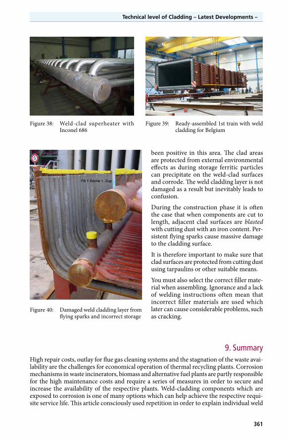
Figure 38: Weld-clad superheater with Inconel 686
Figure 39: Ready-assembled 1st train with weld cladding for Belgium
9. SummaryHigh repair costs, outlay for flue gas cleaning systems and the stagnation of the waste avai-lability are the challenges for economical operation of thermal recycling plants. Corrosion mechanisms in waste incinerators, biomass and alternative fuel plants are partly responsible for the high maintenance costs and require a series of measures in order to secure and increase the availability of the respective plants. Weld-cladding components which are exposed to corrosion is one of many options which can help achieve the respective requi-site service life. This article consciously used repetition in order to explain individual weld
Figure 40: Damaged weld cladding layer from flying sparks and incorrect storage
Wolfgang Hoffmeister, Arne Manzke
362
cladding techniques and demonstrate various options of practical cladding concepts. The minimisation of costly, inferior re-cladding work at the construction site with the highest possible application area being produced under workshop conditions and detailed technical solutions for locally stressed components, e.g. in areas with bent-out tubes, are intended to provide the reader with the opportunity to evaluate the various cladding concepts. As a result of ignorance antiquated concepts are still often applied, leading to undesirable results in operation and, in the worst case, the failure of components. Weld-clad boiler components are very costly as they use nickel-based alloys and the established market standard layer thickness of 2.0 mm. Therefore, from an economic point of view, it is imperative that the weld cladding is implemented with high quality, taking into account constructional options.
In certain fields, weld cladding with a layer thickness of 1.0 mm absolutely represents an alternative to conventional 2.0 mm cladding. On the one hand for reasons of heat transfer and on the other hand because of the reduction of intensive material requirements, this method is a genuine alternative to flame spraying.
10. Literature[1] Zell, L.; Winkel, K.: Einsatz von Schweißplattierungen zur Standzeiterhöhung in Müllverbren-
nungsanlagen. 6. Aachener Schweißtechnik Kolloquium, 24.-25. Juni 1999
[2] Spiegel, M.: Werkstoffe für das Auftragsschweißen für den Korrosionsschutz bei Hochtempera-tur-Korrosionsbeanspruchung. 8. Dresdner Korrosionsschutztage, 24.-25. Oktober 2007.
[3] Heuser, H.: Anforderungen an Schweißzusatzwerkstoffe für Schweißplattierungen von Memb-ranwänden. Thyssen Schweißtechnik Deutschland GmbH, Hamm, Uhlig Schweißplattiersym-posium, Februar 2003
[4] Geipl, H.: Neue Entwicklungen beim MSG-Schweißen von Ni-Werkstoffen. Linde AG, Höllrie-gelskreuth, 6. Aachener Schweißtechnik Kolloquium, 24.-25. Juni 1999
[5] Metschke, J.: Erfahrungen beim Einsatz von Korrosionsschutzmaßnahmen. In: Born, M. (ed.): Dampferzeugerkorrosion. Freiberg: SAXIONA Verlag, 2005, pages 170-213
[6] Schmidl, W.; Herzog, T.; Magel, G.; Müller, W.; Spiegel, W.: Korrosionsschutz im Überhitzerbe-reich – Erfahrungen mit Applikation und Werkstoff aus Qualitätsbegleitungen
[7] Kremser, F; Polak, R: Thermisch Spritzen als in-situ und ex-situ Prozess. In: SAXIONA Standort-entwicklungs- und -verwaltungsgesellschaft mbH (ed. and publisher): Dampferzeugerkorrosion 2009. Freiberg, 2009, pages 203-210
[8] Fronius Deutschland GmbH Sparte Schweißtechnik: Der CMT-Prozess – eine Revolution in der Fügetechnik. Firmenschrift, Goslar, 01/2005