INS# 902-TL1.6A 06 Installation Instructions For TruLine 1 ... · PDF fileusing miter-cut...
22
1 Vertical installations are linear runs of channel beginning at a junction box and ending at a take-up box on a single surface. Runs can be up to 40' in length and the LED strip lays in the bottom of the channel. Vertical installations are typically installed between wall studs or ceiling joists. Cross-braced stud sections or mounting straps are suggested to provide additional support every 32". Vertical Configuration Horizontal installations are linear runs of channel beginning at a junction box and ending at a take-up box on a single surface. Runs can be up to 40' in length and the LED strip lays in the bottom of the channel. Horizontal installations are typically installed perpendicular to wall studs or ceiling joists. Where no stud/joist is present (or in a remodel installation) a mounting strap may be used to secure the channel to the drywall. Horizontal Configuration Section One: Basic Configuration Options SAVE THESE INSTRUCTIONS! - This fixture is wall or ceiling mount. - This instruction shows a typical installation. - Consult the configuration notes on Page 1 before beginning any installation. IMPORTANT INFORMATION 1718 W. Fullerton Ave Chicago, IL 60614 Tel: 773-770-1196 Fax: 773-935-5613 www.purelighting.com [email protected] INS# 902-TL1.6A_06 Installation Instructions For TruLine 1.6A 24VDC © 2016 Pure Lighting. All Rights Reserved.
Transcript of INS# 902-TL1.6A 06 Installation Instructions For TruLine 1 ... · PDF fileusing miter-cut...
1
Vertical installations are linear runs of channel beginning at a junction box and ending at a take-up box on a single surface. Runs can be up to 40' in length and the LED strip lays in the bottom of the channel.
Vertical installations are typically installed between wall studs or ceiling joists. Cross-braced stud sections or mounting straps are suggested to provide additional support every 32".
Vertical Configuration
Horizontal installations are linear runs of channel beginning at a junction box and ending at a take-up box on a single surface. Runs can be up to 40' in length and the LED strip lays in the bottom of the channel.
Horizontal installations are typically installed perpendicular to wall studs or ceiling joists. Where no stud/joist is present (or in a remodel installation) a mounting strap may be used to secure the channel to the drywall.
Horizontal Configuration
Section One: Basic Configuration Options
SAVE THESE INSTRUCTIONS!
- This fixture is wall or ceiling mount.- This instruction shows a typical installation.- Consult the configuration notes on Page 1 before beginning any installation.
IMPORTANT INFORMATION
1718 W. Fullerton AveChicago, IL 60614Tel: 773-770-1196Fax: [email protected]
INS# 902-TL1.6A_06
Installation Instructions For TruLine 1.6A 24VDC
© 2016 Pure Lighting. All Rights Reserved.
2
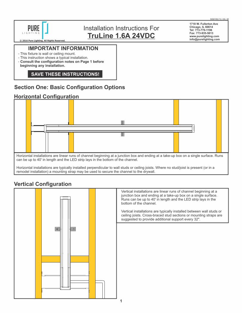
2: Place the lips on the adjustable mounting bars against the studs. Secure the adjustable bars to the studs with the eight #8 screws.
3: Install conduit (if required by local electrial code) and run low-voltage power wires to the junction box.
NOTE: The adjustable mounting bars mount to studs that are spaced 13" to 24" apart.
ADJUSTABLE MOUNTING BAR
STUD #8 SCREW
23
JUNCTIONBOX
CONDUIT W/LOW-VOLTAGE WIRES
B
1: Mount each adjustable mounting bar to one side of the junction box and secure them with the mounting brackets and two Phillips screws provided.
JUNCTIONBOX
1 MOUNTING BRACKET
PHILLIPS SCREW
ADJUSTABLE MOUNTING BAR
INSTALLATION DIRECTION
ASection Two: Standard Horizontal Installation
Zig Zag configurations are used for installations that join runs of TruLine .5A on a single plane (like a ceiling or a wall) using miter-cut sections of channel.
For Zig Zag installations, the LED strip will be installed in the side of the channel to allow the strip to follow the channel corners.
MOUNTINGSTRAP
CHANNEL
LED FLATIN CHANNEL
(SHOWN IN RED)
5/8" MIN.DRYWALL
LENSDRYWALLSCREW
PLASTER
STUD
TAKE-UPBOX
TL1.6ACHANNEL
JUNCTIONBOX
MOUNTINGSTRAP
BRACE
LENS
Zig Zag Configuration
Room-wrapping configurations are used for installations that join runs of TruLine 1.6 on multiple planes (like a ceiling and a wall) using miter-cut linear sections of channel.
For room-wrapping installations, the LED strip will be installed in the bottom of the channel.
MOUNTINGSTRAP
CHANNEL
LED FLATIN CHANNEL
(SHOWN IN RED)
5/8" MIN.DRYWALL
LENSDRYWALLSCREW
PLASTER
STUD
Room-Wrapping ConfigurationMOUNTING
STRAP
CHANNEL
LENS
2X4STUD
BRACE

3
11: Insert the joiner bars halfway into the channel trap door frame. Tighten the two M3 set screws on each joiner bar with a 1.5mm Allen wrench.
12: Slide the other section of channel onto the joining bars and tighten the remaining M3 set screws with a 1.5mm Allen wrench.
11
12CHANNEL
JOINERBAR
TRAP DOOR FRAME
F
8: Connect the red power supply (24VDC+) wires to each red power wire with a wire nut inside the junction box.
9: Connect the black power supply (24VDC-) wires to each black power wire with a wire nut inside the junction box.
10: Place the wire nut connections inside junction box.
NOTE: Remote power supply wires must be present in junction box. Refer to instructions provided with power supply.
JUNCTION BOX
POWER WIRE
8
9
E
NOTE: To install channel in a wall without standard-spaced studs, install perforated mounting straps every 32" behind drywall and secure using two drywall screws. Mark the location of any mounting straps to the drywall.
5: Mark the area where the channel will be located on the drywall using the junction box opening as a guide (MIN 2.25").
6: Cut out the marked area using a "Dremel Multi-Max" or a 6" Fixed Jab Saw.
7: Mark the location of the studs to the drywall for future reference.
MARKING
STUD
MOUNTINGSTRAP
WIDTH OF INSTALLATION
2.25"
5
66
7
D
4: Cut a section of drywall where the junction box will be located using a 6" fixed jab saw or other appropriate tool.
6" FIXEDJAB SAW
4
C
10

4
16: Insert the #4-40 Torx screws through the end cap holes and thread into the TruLine 1.6A channel.
17: Tighten the end cap to the channel using the provided T10 screwdriver.
END CAP
TRAP DOOR FRAME
17
T10 TORX
16
J
14: Place both power connector into the end cap insert.
15: Slide the assembled end cap insert and power connectors into the end cap.
END CAP
END CAPINSERT
POWERCONNECTOR
14
15
I
NOTE: If cutting channel to length, ensure that the lens is also cut to match the total length of the installation.
H
G
13: Snap the lens into the assembled trap door frame and channel BEFORE cutting to length. This ensures a proper fit after installation.
CHANNEL
TRAP DOOR FRAME
LENS
13
STARTERSECTION
CHANNELSECTION
CUT LENS LENGTH TO TOTAL LENGTH
LENS

5
22: Use a 12" compound knife for a smooth compound spread. Sand, paint, and finish the plaster and drywall before removing the
blue contractor’s tape.
12" COMPOUNDKNIFE
PLASTER CONTRACTOR'S TAPE
22
N
21: Apply ultra-thin drywall tape along edges of channel to prevent cracking of plaster after installation.
NOTE: Cover the channel opening with blue contractor’s tape before plastering.
NOTE: Test the LED strip before any plaster work is done.
ULTRA THINDRYWALL TAPE
21
M
19: Using the mark locations on the drywall, carefully make holes in the channel flange using the provided square drill with counter sink bit.
20: Secure the channel to the stud through the drywall with the #6 screws using the provided square recess bit.
POWER FEEDJUNCTION BOX
#6 SCREW
MARKING
20
ENDCAP
#6 SCREW
MARKING
CHANNEL
19
L
18: Slide the take-up box onto the non-power channel end and tighten the M3 set screws with a 1.5mm Allen wrench.
18
CHANNEL
TAKE-UP BOXK

6
NOTE: If installation requires RGB, RGB+W, or Tunable White, refer to wiring diagrams on pages 19-21.
24: Remove the blue contractor’s tape from the inside of the channel. Clean the channel surface with alcohol to remove any dust or debris before continuing.
25: Attach the trap door to the junction box using the #6-32 screw.
TRAP DOOR
#6-32SCREW 24
25
P
23: Carefully use a flathead screwdriver to remove excess drywall from the internal bevel/edge.
WALL
TRULINE CHANNEL
FLATHEADSCREWDRIVER
23
O
25

7
2: Remove a knockout to install the power line conduit (if required by local electrical code.
3: Install the conduit and run the low voltage 24VDC power wires coming from the remote power supply to the junction box.
4: Refer to the instruction provided with the power supply along with the wiring diagram for proper wiring.
STUD
ADJUSTABLE MOUNTING BAR
CONDUITJUNCTIONBOX
3
T
1: Mount each adjustable mounting bar to one side of the junction box and secure them with the mounting brackets and two Phillips screws provided.
JUNCTIONBOX
MOUNTING BRACKET
ADJUSTABLE MOUNTING BAR
PHILLIPS SCREW
VERTICAL ORIENTATION
1INS
TA
LLA
TIO
ND
IRE
CT
ION
S
Section Three: Vertical Installation
29: Snap the lens back onto the channel. Ensure lens is fully seated.
29
NOT INSTALLEDCORRECTLY
CORRECT
29
R
26: Line up the red wire side of the power connector with the “+24VDC” marking on the Soft Strip. Push the male connector of the
Soft Strip into the female connector of the power cables.
27: Carefully remove the backing from the LED soft strip, making sure not to remove the tape from the soft strip. Firmly press down The adhesive portion of the soft strip onto the channel surface while removing the rest of the backing, making sure there are no air bubbles that can cause surface irregularities.
28: If required, trim the soft strip on the dashed cuttable section, place the excess soft strip inside the take up box (see inset). Ensure the entire length of the channel is covered with Soft Strip to avoid unlit areas.
CHANNEL
SOFT STRIP
PAPER BACKING
TRAP DOOR
POWER WIRE
27
26TAKE UPBOX
EXCESSSOFT STRIP
28
Q

8
8: Install mounting straps behind the drywall (suggested spacing is every 32") by threading a drywall screw into the perforated material.
9: Place the mounting strap behind the cut drywall and rotate into place using the drywall screw as a handle.
10: Secure the mounting strap to the drywall using two drywall screws. Mark the location on the drywall.
NOTE: Complete mounting, plastering, painting, and LED strip installation by following Steps 14 through 29 in Section One.
910 10
MOUNTINGSTRAP
JUNCTIONBOX
DRYWALLSCREW
W
5: Mark the area where the channel will be located on the drywall.
6: Cut out the marked area using appropriate tools.
7: Mark the location of the studs on the drywall for future reference.
DRYWALL
2.25"
INSTALLATIONHEIGHT
STUD
JUNCTIONBOX
5
6
6" FIXEDJAB SAW
V
NOTE: If cutting channel to length, ensure that the lens is also cut to match the total length of the installation.
U STARTERSECTION
CHANNELSECTION
CUT LENS LENGTH TO TOTAL LENGTH
LENS
9
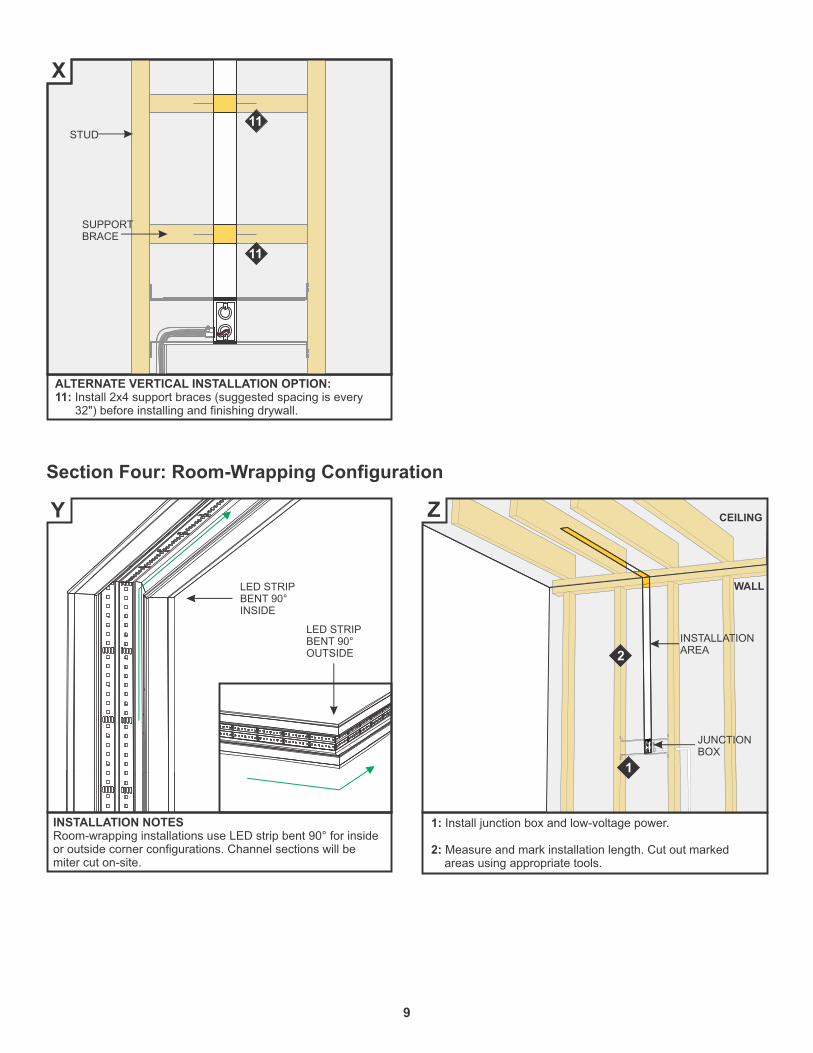
1: Install junction box and low-voltage power.
2: Measure and mark installation length. Cut out marked areas using appropriate tools.
1
WALL
CEILING
JUNCTIONBOX
INSTALLATIONAREA
Z
INSTALLATION NOTESRoom-wrapping installations use LED strip bent 90° for inside or outside corner configurations. Channel sections will be miter cut on-site.
Y
Section Four: Room-Wrapping Configuration
ALTERNATE VERTICAL INSTALLATION OPTION:11: Install 2x4 support braces (suggested spacing is every 32") before installing and finishing drywall.
STUD
SUPPORTBRACE
11
11
X
2
LED STRIPBENT 90°INSIDE
LED STRIPBENT 90°OUTSIDE
10
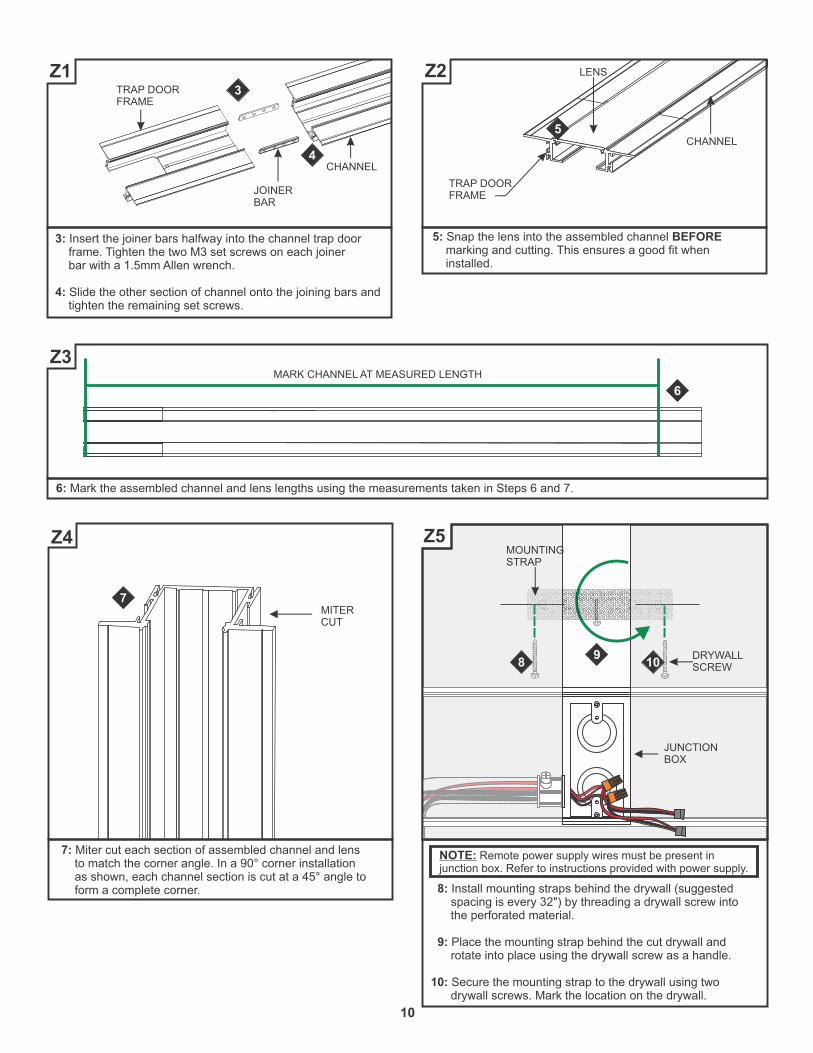
6: Mark the assembled channel and lens lengths using the measurements taken in Steps 6 and 7.
MARK CHANNEL AT MEASURED LENGTH
6
Z3
5: Snap the lens into the assembled channel BEFORE marking and cutting. This ensures a good fit when installed.
CHANNEL
TRAP DOOR FRAME
LENS
5
Z2
3: Insert the joiner bars halfway into the channel trap door frame. Tighten the two M3 set screws on each joiner bar with a 1.5mm Allen wrench.
4: Slide the other section of channel onto the joining bars and tighten the remaining set screws.
3
4CHANNEL
JOINERBAR
TRAP DOOR FRAME
Z1
8: Install mounting straps behind the drywall (suggested spacing is every 32") by threading a drywall screw into the perforated material.
9: Place the mounting strap behind the cut drywall and rotate into place using the drywall screw as a handle.
10: Secure the mounting strap to the drywall using two drywall screws. Mark the location on the drywall.
NOTE: Remote power supply wires must be present in junction box. Refer to instructions provided with power supply.
MOUNTINGSTRAP
JUNCTIONBOX
DRYWALLSCREW
98 10
Z5
7: Miter cut each section of assembled channel and lens to match the corner angle. In a 90° corner installation as shown, each channel section is cut at a 45° angle to form a complete corner.
Z4
MITERCUT
7
11
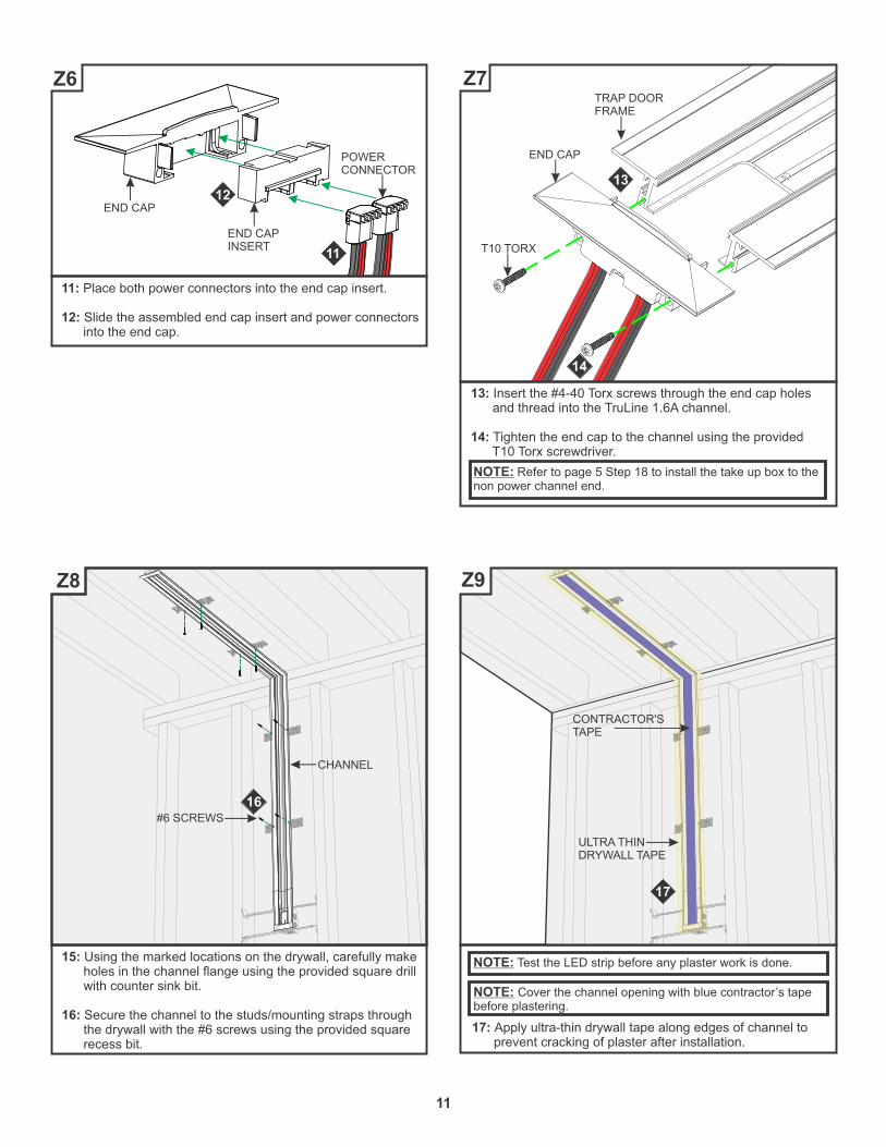
13: Insert the #4-40 Torx screws through the end cap holes and thread into the TruLine 1.6A channel.
14: Tighten the end cap to the channel using the provided T10 Torx screwdriver.
END CAP
TRAP DOOR FRAME
14
T10 TORX
13
Z7
11: Place both power connectors into the end cap insert.
12: Slide the assembled end cap insert and power connectors into the end cap.
END CAP
END CAPINSERT
POWERCONNECTOR
11
12
Z6
17: Apply ultra-thin drywall tape along edges of channel to prevent cracking of plaster after installation.
NOTE: Cover the channel opening with blue contractor’s tape before plastering.
NOTE: Test the LED strip before any plaster work is done.
17
ULTRA THINDRYWALL TAPE
CONTRACTOR'STAPE
Z9
15: Using the marked locations on the drywall, carefully make holes in the channel flange using the provided square drill with counter sink bit.
16: Secure the channel to the studs/mounting straps through the drywall with the #6 screws using the provided square recess bit.
16
Z8
NOTE: Refer to page 5 Step 18 to install the take up box to the non power channel end.

12
19: Carefully use a flathead screwdriver to remove excess drywall from the internal bevel/edge.
WALL
TRULINE CHANNEL
FLATHEADSCREWDRIVER
19
Z11
18: Use a 12" compound knife for a smooth compound spread. Sand, paint, and finish the plaster and drywall before removing the blue contractor’s tape.
18PLASTER
12" COMPOUNDKNIFE
Z10
22: Line up the red wire side of the power connector with the “+24VDC” marking on the Soft Strip. Push the male connector of the Soft Strip into the female connector of the power cables.
23: Carefully remove the backing from the LED soft strip, making sure not to remove the tape from the soft strip.
24: Firmly press down the adhesive portion of the soft strip onto the channel surface while removing the rest of the backing, making sure there are no air bubbles that can cause surface irregularities.
NOTE: If installation requires RGB, RGB+W, or Tunable White, refer to wiring diagrams on pages 19-21.
22
LED SOFTSTRIP
24
POWERCONNECTOR
23
Z13
20: Remove the blue contractors tape from the inside of the channel. Clean the channel surface with alcohol to remove any dust or debris before continuing.
21: Attach the trap door and frame to the junction box using the #6-32 screws.
Z12
21
TRAP DOOR
#6-32SCREWS

13
25: Continue removing the paper backing from the soft strip and installing along channel, pressing adhesive into place using ONLY a finger.
26: Bend the soft strip to match the installation corner. Ensure the entire length of the channel is covered with Soft Strip to avoid unlit areas.
LED SOFTSTRIP
25
PAPERBACKING
26
Z14
27: If required, trim the soft strip on the dashed cutting lines. Place the excess soft strip inside the take-up box.
27
LED SOFTSTRIP
TAKE-UPBOX
Z15
28: Repeat Steps 22 through 27 to install the second LED soft
strip to the channel.
13
Z16
29: Snap the lens back onto the channel sections. Ensure lens is fully seated.
CORRECT
29
NOT INSTALLEDCORRECTLY
29
Z17
14
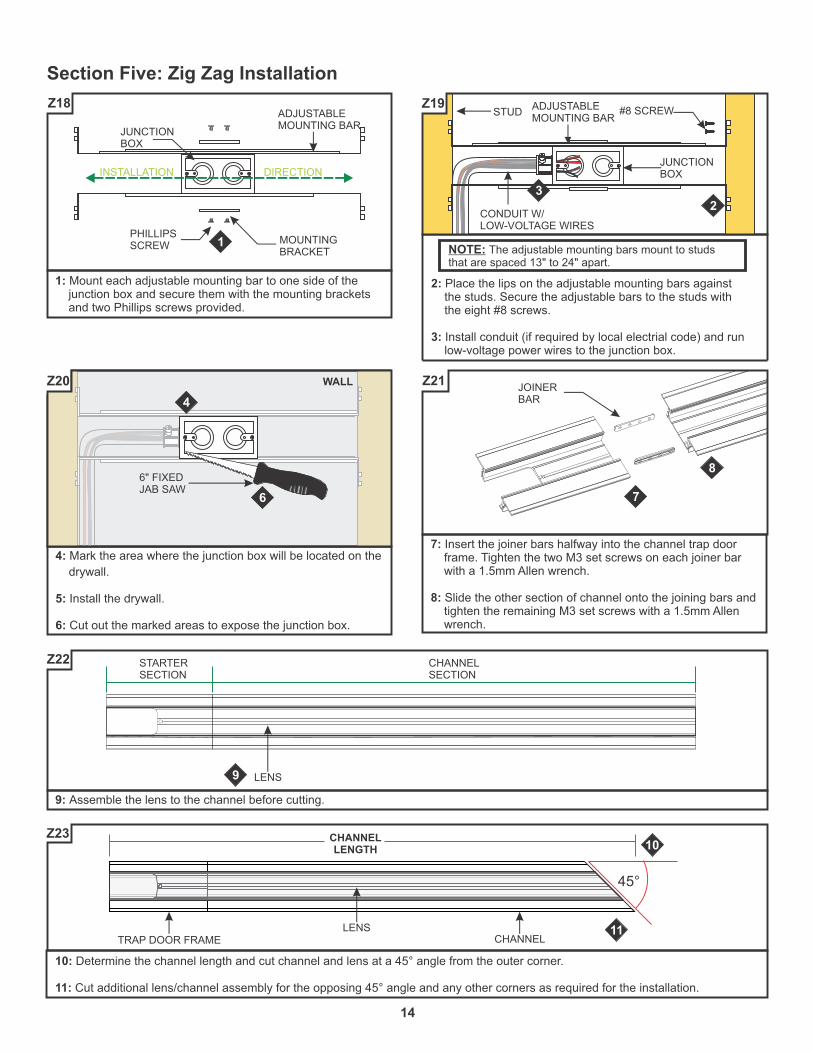
10: Determine the channel length and cut channel and lens at a 45° angle from the outer corner.
11: Cut additional lens/channel assembly for the opposing 45° angle and any other corners as required for the installation.
45°
CHANNELTRAP DOOR FRAME
CHANNELLENGTH
LENS
10
11
Z23
9: Assemble the lens to the channel before cutting.
STARTERSECTION
CHANNELSECTION
LENS9
Z22
7: Insert the joiner bars halfway into the channel trap door frame. Tighten the two M3 set screws on each joiner bar with a 1.5mm Allen wrench.
8: Slide the other section of channel onto the joining bars and tighten the remaining M3 set screws with a 1.5mm Allen wrench.
7
8
Z21
4: Mark the area where the junction box will be located on the
drywall.
5: Install the drywall.
6: Cut out the marked areas to expose the junction box.
6" FIXEDJAB SAW
4
6
WALLZ20
2: Place the lips on the adjustable mounting bars against the studs. Secure the adjustable bars to the studs with the eight #8 screws.
3: Install conduit (if required by local electrial code) and run low-voltage power wires to the junction box.
NOTE: The adjustable mounting bars mount to studs that are spaced 13" to 24" apart.
ADJUSTABLE MOUNTING BAR
STUD #8 SCREW
23
JUNCTIONBOX
CONDUIT W/LOW-VOLTAGE WIRES
Z19
1: Mount each adjustable mounting bar to one side of the junction box and secure them with the mounting brackets and two Phillips screws provided.
JUNCTIONBOX
1 MOUNTING BRACKET
PHILLIPS SCREW
ADJUSTABLE MOUNTING BAR
INSTALLATION DIRECTION
Z18
Section Five: Zig Zag Installation
JOINERBAR

15
19: Slide the take-up box onto the non-power channel end and tighten the M3 set screws with a 1.5mm Allen wrench.
19
CHANNEL
TAKE-UP BOX
Z27
16: Connect the red power supply (24VDC+) wires to each red power wire with a wire nut inside the junction box.
17: Connect the black power supply (24VDC-) wires to each black power wire with a wire nut inside the junction box.
18: Place the wire nut connections inside junction box.
NOTE: Remote power supply wires must be present in junction box. Refer to instructions provided with power supply.
JUNCTION BOX
POWER WIRE
16
17
Z26
NOTE: To install channel vertically or in a wall without standard-spaced studs, install perforated mounting straps every 32" behind drywall and secure using two drywall screws. Mark the location of any mounting straps to the drywall.
13: Mark the area where the channel will be located on the drywall using the junction box opening as a guide (MIN 2.25" wide).
14: Cut out the marked area(s) using a Dremel Multi-Max or a 6" Fixed Jab Saw.
15: Mark the location of the studs to the drywall for future reference.
MARKING
STUD
MOUNTINGSTRAP
2.25"
2.2
5"
13
14
15
Z25
12: Mark location of junction box. Cut out drywall to expose junction box using a 6" Fixed Jab Saw or equivalent tool.
6" FIXEDJAB SAW
12
Z24
18
16
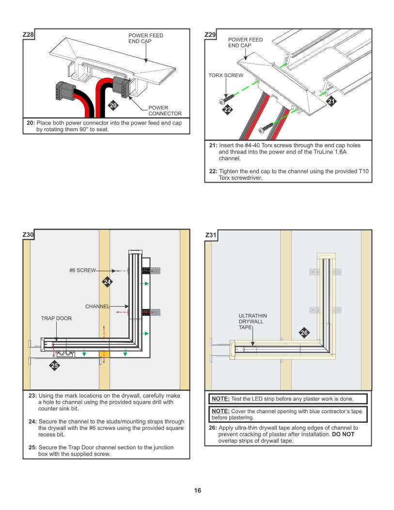
26: Apply ultra-thin drywall tape along edges of channel to prevent cracking of plaster after installation. DO NOT overlap strips of drywall tape.
NOTE: Test the LED strip before any plaster work is done.
ULTRATHINDRYWALLTAPE
26
Z31
23: Using the mark locations on the drywall, carefully make a hole to channel using the provided square drill with counter sink bit.
24: Secure the channel to the studs/mounting straps through the drywall with the #6 screws using the provided square recess bit.
25: Secure the Trap Door channel section to the junction box with the supplied screw.
#6 SCREW
24
25
CHANNEL
TRAP DOOR
Z30
21: Insert the #4-40 Torx screws through the end cap holes and thread into the power end of the TruLine 1.6A channel.
22: Tighten the end cap to the channel using the provided T10 Torx screwdriver.
21
TORX SCREW
POWER FEEDEND CAP
22
Z29
20: Place both power connector into the power feed end cap by rotating them 90° to seat.
20
POWER FEEDEND CAP
POWERCONNECTOR
Z28
NOTE: Cover the channel opening with blue contractor’s tape before plastering.

17
31: Line up the red wire side of the power connector with the “+24VDC” marking on the Soft Strip. Push the male connector of the Soft Strip into the female connector of the power cables.
32: Carefully remove the backing from the LED soft strip, making sure not to remove the tape from the soft strip. Firmly press down the adhesive portion of the soft strip onto the channel surface while removing the rest of the backing, making sure there are no air bubbles that can cause surface irregularities.
NOTE: If installation requires RGB, RGB+W, or Tunable White, refer to wiring diagrams on pages 19-21.
31
32
POWERCONNECTION
LED STRIPPAPERBACKING
Z35
29: Remove the blue contractors tape from the inside of the channel. Clean the channel surface with alcohol to remove any dust or debris before continuing.
30: Attach the trap door to the junction box using the #6-32 screw.
30
TRAP DOOR
#6-32SCREW
Z34
28: Carefully use a flathead screwdriver to remove excess drywall from the internal bevel/edge.
WALLTRULINE CHANNEL
FLATHEADSCREWDRIVER
28
Z33
27: Use a 12" compound knife for a smooth compound spread. Sand, paint, and finish the plaster and drywall before removing the blue contractors tape.
27
Z32
29
18
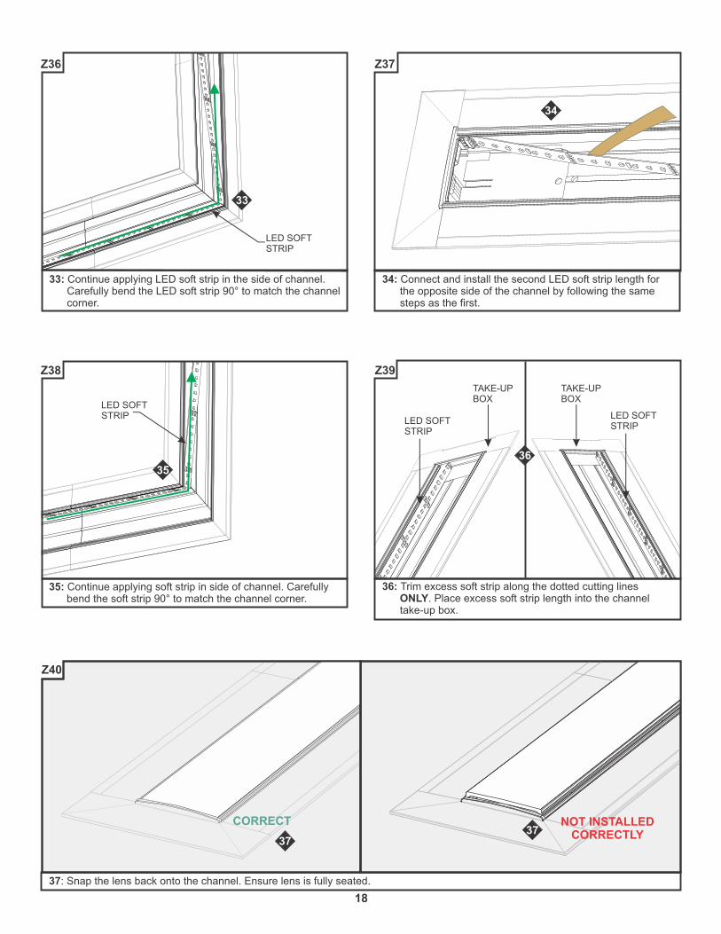
37: Snap the lens back onto the channel. Ensure lens is fully seated.
CORRECT
37
NOT INSTALLEDCORRECTLY37
Z40
36: Trim excess soft strip along the dotted cutting lines ONLY. Place excess soft strip length into the channel take-up box.
TAKE-UPBOX
TAKE-UPBOX
LED SOFTSTRIP
LED SOFTSTRIP
36
Z39
35: Continue applying soft strip in side of channel. Carefully bend the soft strip 90° to match the channel corner.
35
LED SOFTSTRIP
Z38
34: Connect and install the second LED soft strip length for the opposite side of the channel by following the same steps as the first.
34
Z37
33: Continue applying LED soft strip in the side of channel. Carefully bend the LED soft strip 90° to match the channel corner.
33
LED SOFTSTRIP
Z36

19
M
Ext in-
Ext in+
DMX in +
DMX in -
DMX in shield
LedSync thru+
LedSync thru-
LedSync shield
LED supply +
Group 1 -
Group 2 -
Group 3 -
Group 4 -
Driver
M
Ext in-
Ext in+
DMX in +
DMX in -
DMX in shield
LedSync thru+
LedSync thru-
LedSync shield
LED supply +
Group 1 -
Group 2 -
Group 3 -
Group 4 -
Driver
120VAC 24VDC
120VAC 24VDC
(+)
VDC+VDC-
24VD
C+
-
LINE
N L
(-)
(+)
(-)
VDC+VDC-
12
0V
AC
L
L
N
N
120VAC24VDC
(+)(-)
DMX CABLE
CTP
CDP
POWER SUPPLY
CDP/CTP CONTROLLER
RGB LED SOFT STRIPS
CONTROLLERPOWER SUPPLY
DVR-RGB
DMX CABLE
Using LED Power Supply with RGB Soft Strip & CDP or CTP Control
Standard RGB Configuration
NEU
HOT
INPUT120VAC
ELV DIMMER
120VAC (HOT)
BLACK (HOT)
WHITE (NEUTRAL)
GND
SS__-24V-___
POWER SUPPLY
SS__-24V-___
POWER SUPPLY
General 24VDC Configuration
Section Six: Wiring Diagrams
POWER SUPPLY
20
NEU
HOT
HOT
NEU
120VAC (HOT)
BLACK (HOT)
WHITE (NEUTRAL)
GND
BLACK (HOT)
WHITE (NEUTRAL)
GND120VAC (HOT)
INPUT120VAC
ELV DIMMER
INPUT120VAC
ELV DIMMER
+24VDCRED
-24VDCBLACK
+24VDCRED
-24VDCBLACK
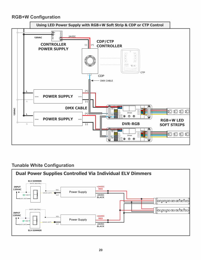
Dual Power Supplies Controlled Via Individual ELV Dimmers
Tunable White Configuration
M
Ext in-
Ext in+
DMX in +
DMX in -
DMX in shield
LedSync thru+
LedSync thru-
LedSync shield
LED supply +
Group 1 -
Group 2 -
Group 3 -
Group 4 -
Driver
M
Ext in-
Ext in+
DMX in +
DMX in -
DMX in shield
LedSync thru+
LedSync thru-
LedSync shield
LED supply +
Group 1 -
Group 2 -
Group 3 -
Group 4 -
Driver
120VAC 24VDC
120VAC 24VDC
(+)
VDC+VDC-
24VD
C+
-
LINE
N L
(-)
(+)
(-)
VDC+VDC-
12
0V
AC
L
L
N
N
120VAC24VDC
(+)(-)
DMX CABLE
CTP
CDP
POWER SUPPLY
CDP/CTP CONTROLLER
RGB+W LED SOFT STRIPS
CONTROLLERPOWER SUPPLY
DVR-RGB
DMX CABLE
Using LED Power Supply with RGB+W Soft Strip & CDP or CTP Control
RGB+W Configuration
POWER SUPPLY
Power Supply
Power Supply
21
M
Ext in-
Ext in+
DMX in +
DMX in -
DMX in shield
LedSync thru+
LedSync thru-
LedSync shield
LED supply +
Group 1 -
Group 2 -
Group 3 -
Group 4 -
Driver
M
Ext in-
Ext in+
DMX in +
DMX in -
DMX in shield
LedSync thru+
LedSync thru-
LedSync shield
LED supply +
Group 1 -
Group 2 -
Group 3 -
Group 4 -
Driver
120VAC 24VDC
120VAC 24VDC
(+)
VDC+VDC-
24VD
C+
-
LINE
N L
(-)
(+)
(-)
VDC+VDC-
L
L
N
N
120VAC24VDC
(+)(-)
DMX CABLE
CTP
CDP
+24VDC
+24VDC
+
+
+
+
-
-
-
-
120V
AC
O N
1 2 3 4 5 6 7
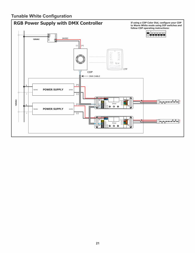
If using a CDP Color Dial, configure your CDP to Warm White mode using DIP switches andfollow CDP operating instructions:
RGB Power Supply with DMX Controller
Tunable White Configuration
POWER SUPPLY
POWER SUPPLY

1: To remove tape residue from back of the strip, apply WD-40, Goo Gone, or a mixture of warm water and lemon oil to the corner of a clean, dry towel. Gently buff the area containing the adhesive residue until it is completely removed.
2: Gently remove a few inches of the from one side of the tape backing. Attach the adhesive tape to the back of the soft strip and apply moderate pressure to affix the tape. Continue this step a few inches at the time until the entire adhesive tape is attached to back of the soft strip.
3: Refer to pages 7, 13, or 17 to reinstall the LED soft strip.
NOTE: If relocating the installed soft strip, make sure that the adhesive tape on back of the soft strip covers the entire strip. The adhesive tape isolates the strip from the installation surface. Damaged or inconsistent adhesive tape may cause the contacts on the back of the strip to come in contact with the conductive heat sink which will cause the strip to short and burn. Call Edge Lighting to get replacement adhesive tape and/or optional aluminum heat sink tape (SS-HR-F).
ADHESIVE BACKING
ADHESIVE
BACK SIDE OF SOFT STRIP
2
ADHESIVE TAPE
APPLY ADHESIVE REMOVER AND THEN BUFF OFF
1
SOFT STRIP REMOVE SOFT STRIPTO RELOCATE
ADHESIVE TAPE
+24VDC +24VDC
+24VDC
Z41
Relocating Soft Strip (Optional)
DO NOT use any tool to install soft strip to a surface. This will damage the soft strip component.
DO only ever use fingers to gently install soft strip to a surface AFTER cleaning the surface with alcohol.
DO NOT pull the strip back towards itself. Doing so risks damaging the strip and making it not function.
DO gently pull up and away from the soft strip if removing to reposition. This avoids damaging the strip.
IMPORTANT INFORMATION REGARDING INSTALLATION AND REWORK OF SOFT STRIP LED
22