DR4500A Truline Circular Chart Recorder With or …...Release H DR4500A Truline Circular Chart...
290
DR4500A Truline Circular Chart Recorder With or Without Control Product Manual Doc. No.: 44-45-25-30 Release: H Last Revision Date: 8/99
Transcript of DR4500A Truline Circular Chart Recorder With or …...Release H DR4500A Truline Circular Chart...

DR4500A Truline Circular ChartRecorder With or Without Control
Product Manual
Doc. No.: 44-45-25-30
Release: H
Last Revision Date: 8/99

ii DR4500A Truline Circular Chart Recorder With or Without Control Product Manual Release H 8/99
Notices and Trademarks
Copyright 1999 by Honeywell Inc.Release August, 1999
While this information is presented in good faith and believed to be accurate, Honeywell disclaims the impliedwarranties of merchantability and fitness for a particular purpose and makes no express warranties except as may
be stated in its written agreement with and for its customers.
In no event is Honeywell liable to anyone for any indirect, special or consequential damages. The information andspecifications in this document are subject to change without notice.
DR4500 Truline is a U.S. registered trademark of Honeywell Inc.
Other brand or product names are trademarks of their respective owners.
Honeywell Inc.
Industrial Automation and Control
Automation College
2820 West Kelton Lane
Phoenix, AZ 85053-3028
1-800 852-3211

Release H DR4500A Truline Circular Chart Recorder With or Without Control Product Manual iii8/99
About This Document
ReferencesThe following list identifies all documents that may be sources of reference for material discussed in thispublication.
Document Title Doc ID
How to Apply Digital Instrumentation in Severe ElectricalNoise Environments
51-52-05-01
Contacts
World Wide Web
The following lists Honeywell’s World Wide Web sites that will be of interest to our industrial automation andcontrol customers.
Honeywell Organization WWW Address (URL)
Corporate http://www.honeywell.com
Industrial Automation and Control http://www.iac.honeywell.com
International http://www.honeywell.com/Business/global.asp
TelephoneContact us by telephone at the numbers listed below.
Organization Phone Number
United States and Canada Honeywell Inc.Industrial Automation and Control
1-800-423-9883 Tech. Support1-800-525-7439 Service
Asia Pacific Honeywell Asia Pacific Inc.Hong Kong
(852) 8298298
Europe Honeywell PACE, Brussels, Belgium [32-2] 728-2111
Latin America Honeywell Inc., Sunrise, Florida U.S.A. (305) 364-2355

iv DR4500A Truline Circular Chart Recorder With or Without Control Product Manual Release H 8/99
Symbol DefinitionsThe following table lists those symbols used in this document to denote certain conditions.
Symbol Definition
This CAUTION symbol on the equipment refers the user to the Product Manual foradditional information. This symbol appears next to required information in the manual.
This WARNING symbol on the equipment refers the user to the Product Manual foradditional information. This symbol appears next to required information in the manual.
WARNING: risk of electrical shock. This symbol warns the user of a potential shockhazard where HAZARDOUS LIVE voltages greater than 30 Vrms, 42.4 Vpeak, or 60VDC may be accessible.
ATTENTION, Electrostatic Discharge (ESD) hazards. Observe precautions forhandling electrostatic sensitive devices
Protective Earth (PE) terminal. Provided for connection of the protective earth (greenor green/yellow) supply system conductor.
Functional earth terminal. Used for non-safety purposes such as noise immunityimprovement. NOTE: This connection shall be bonded to protective earth at thesource of supply in accordance with national local electrical code requirements.
Earth Ground. Functional earth connection. NOTE: This connection shall be bonded toProtective earth at the source of supply in accordance with national and local electricalcode requirements.
Chassis Ground. Identifies a connection to the chassis or frame of the equipment shallbe bonded to Protective Earth at the source of supply in accordance with national andlocal electrical code requirements.

Release H DR4500A Truline Circular Chart Recorder With or Without Control Product Manual v8/99
Contents
1. Overview ...........................................................................................1
1.1 Introduction ........................................................................................................1
1.2 Operator Interface .............................................................................................3
1.3 Set-up Tasks .....................................................................................................5
2. Installation .........................................................................................7
2.1 Overview............................................................................................................7
2.2 Model Number Interpretation...........................................................................13
2.3 Mounting Considerations and Overall Dimensions .........................................16
2.4 Mounting Methods ...........................................................................................17
2.5 Wiring Prerequisites ........................................................................................24
2.6 Input Wiring Procedures ..................................................................................26
2.7 Output Wiring Procedures ...............................................................................36
2.8 Option Wiring Procedures ...............................................................................42
2.9 Lockout Switch Configuration..........................................................................51
3. Configuration ...................................................................................53
3.1 Overview..........................................................................................................53
3.2 Configuration Prompts.....................................................................................55
3.3 How To Get Started.........................................................................................58
3.4 Configuration Tips ...........................................................................................59
3.5 Configuration Procedure..................................................................................60
3.6 Input Set Up Group..........................................................................................62
3.7 Pen Set Up Group ...........................................................................................64
3.8 Chart Set Up Group.........................................................................................65
3.9 Time Set Up Group..........................................................................................67
3.10 Totalizer Set Up Group....................................................................................68
3.11 Input Algorithm Set Up Group .........................................................................69
3.12 Control Set Up Group ......................................................................................70
3.13 Tuning Parameters Set Up Group...................................................................72
3.14 SP Ramp Set Up Groups ................................................................................73
3.15 Timer Set Up Group ........................................................................................74
3.16 Alarms Set Up Group ......................................................................................75
vi DR4500A Truline Circular Chart Recorder With or Without Control Product Manual Release H 8/99
3.17 Auxiliary Output Set Up Group ........................................................................77
3.18 Modbus Communications Set Up Group.........................................................78
3.19 Options Set Up Group .....................................................................................79
3.20 Event Message Configuration .........................................................................80
3.21 Lockout Set Up Group .....................................................................................83
3.22 Adjust Printing..................................................................................................84
3.23 Configuration Record Sheet ............................................................................85
4. Configuration Parameter Definitions................................................89
4.1 Overview..........................................................................................................89
4.2 Input Parameters Set Up Group......................................................................90
4.3 Pen Parameters Set Up Group........................................................................94
4.4 Chart Parameters Set Up Group .....................................................................96
4.5 Time Parameters Set Up Group......................................................................99
4.6 Total Parameters Set Up Group....................................................................100
4.7 Input Algorithm Set Up Group .......................................................................102
4.8 Control Parameters Set Up Group ................................................................105
4.9 Tuning Parameters Set Up Group.................................................................115
4.10 Setpoint Ramp Set Up Group........................................................................118
4.11 Timer Set Up Group ......................................................................................120
4.12 Alarms Set Up Group ....................................................................................121
4.13 Auxiliary Output Set Up Group ......................................................................124
4.14 Modbus Communications Set Up Group.......................................................126
4.15 Options Set Up Group ...................................................................................127
4.16 Event Message Set Up Group.......................................................................129
4.17 Lockout Parameters Set Up Group ...............................................................130
4.18 Printing Characteristics Adjustments.............................................................131
5. Operation.......................................................................................133
5.1 Overview........................................................................................................133
5.2 Start-up ..........................................................................................................134
5.3 Monitoring Your Recorder .............................................................................138
5.4 Operator Functions........................................................................................144
5.5 Operating Modes ...........................................................................................145
5.6 Setpoints........................................................................................................147
5.7 Single Setpoint Ramp....................................................................................149
5.8 Using Two Sets of Tuning Constants (PID Values).......................................152

Release H DR4500A Truline Circular Chart Recorder With or Without Control Product Manual vii8/99
5.9 Using Accutune II...........................................................................................155
5.10 Alarm Setpoints .............................................................................................159
5.11 Three Position Step Control Algorithm ..........................................................160
5.12 Digital Input Option (Remote Switching) .......................................................161
5.13 Resetting and Displaying Totalizer Value......................................................162
5.14 Monitoring the External Event Operation ......................................................163
5.15 Maximizing Pen Life ......................................................................................164
5.16 Routine Maintenance.....................................................................................165
5.17 Installing/Replacing Chart..............................................................................166
5.18 Chart Operation .............................................................................................167
6. Setpoint Ramp/Soak Programming and Operation .......................169
6.1 Overview........................................................................................................169
6.2 Setpoint Program Contents ...........................................................................171
6.3 Drawing a Ramp/Soak Profile .......................................................................174
6.4 Entering the Setpoint Program Data .............................................................179
6.5 SP RAMP 1 and SPRAMP 2 Set Up Group ..................................................181
6.6 Setpoint Program Segments Set Up Group ..................................................183
6.7 Setpoint Program Event Set Up Group .........................................................186
6.8 Run/Monitor the Program ..............................................................................190
7. Input Calibration ............................................................................193
7.1 Overview........................................................................................................193
7.2 Restoring Factory Calibration ........................................................................194
7.3 Minimum and Maximum Range Values.........................................................196
7.4 Preliminary Information..................................................................................197
7.5 Calibration Set Up and Wiring for PV Inputs .................................................199
7.6 Calibration Procedure....................................................................................208
7.7 Printing Characteristics Adjustments.............................................................211
8. Output Calibration..........................................................................213
8.1 Overview........................................................................................................213
8.2 Current Proportional Output Calibration ........................................................214
8.3 Position Proportional and Three Position Step Output Calibration ..............216
8.4 Auxiliary Output Calibration ...........................................................................219
9. Troubleshooting / Service..............................................................221

viii DR4500A Truline Circular Chart Recorder With or Without Control Product Manual Release H 8/99
9.1 Overview........................................................................................................221
9.2 Troubleshooting Aids.....................................................................................223
9.3 Self Diagnostics .............................................................................................225
9.4 Visual Failure Symptoms...............................................................................231
9.5 Troubleshooting Procedures .........................................................................232
10. Parts List ....................................................................................239
10.1 Overview........................................................................................................239
10.2 Exploded Views .............................................................................................240
10.3 Miscellaneous Hardware Kit Contents ..........................................................246
10.4 Internal Cabling Data.....................................................................................247
10.5 Internal Wiring Diagram – Options Only........................................................248
A. Model DR45AR .............................................................................249
A.1 Overview........................................................................................................249
A.2 Hardware Identification..................................................................................250
A.3 Fo Reset Configuration..................................................................................252
A.4 Options Configuration....................................................................................253
A.5 Operations Additions .....................................................................................255
A.6 Configuration Worksheet Additions ...............................................................256
B. Security Lockout ............................................................................257
B.1 Overview........................................................................................................257
Multilanguage Safety Instructions

Release H DR4500A Truline Circular Chart Recorder With or Without Control Product Manual ix8/99
TablesTable 1-1 Function of Keys .........................................................................................................................................4Table 2-1 Operating Limits and Condensed Specifications .........................................................................................8Table 2-2 Procedure to Access Components..............................................................................................................14Table 2-3 Mounting Flush in a New Panel Cutout.....................................................................................................18Table 2-4 Reference Data for Mounting DR4500A in Existing Panel Cutouts .........................................................19Table 2-5 Mounting Flush in a Panel Using Universal Filler Kit ..............................................................................20Table 2-6 Mounting Flush in a Panel Using Kent Model 105M Cutout ............................................................. .......21Table 2-7 Mounting Flush on a Surface (of Panel or Wall)..................................................................... ..................22Table 2-8 Permissible Wiring Bundling ........................................................................................ ............................25Table 2-9 AC Line Power Wiring............................................................................................... ...............................28Table 2-10 Thermocouple, RTD, Radiamatic, mV, or 0–5 Vdc Input Wiring...........................................................30Table 2-11 4-20 mA Input Wiring .............................................................................................................................32Table 2-12 0-10 Volt dc Input Wiring .......................................................................................................................34Table 2-13 4-20 mA Control Output Wiring .............................................................................................................36Table 2-14 Position Proportional Control Output Wiring..........................................................................................38Table 2-15 Relay Control Output Wiring ..................................................................................................................40Table 2-16 Alarm Output or Digital Input Wiring.....................................................................................................42Table 2-17 Alarm 3 and Alarm 4 Output Wiring.......................................................................................................44Table 2-18 Alarm 5 and Alarm 6 Output Wiring.......................................................................................................45Table 2-19 RS485 Modbus Communications Wiring................................................................................................47Table 2-20 4-20 mA Auxiliary Output Wiring ..........................................................................................................49Table 3-1 Configuration Tips.....................................................................................................................................59Table 3-2 Configuration Procedure............................................................................................................................60Table 3-3 Input Group Function Prompts ..................................................................................................................62Table 3-4 Pen 1, 2, 3, 4 Group Function Prompts......................................................................................................64Table 3-5 Chart Group Function Prompts..................................................................................................................65Table 3-6 Time Group Function Prompts ..................................................................................................................67Table 3-7 Totalizer Group Function Prompts ............................................................................................................68Table 3-8 Input Algorithm Group Function Prompts.................................................................................................69Table 3-9 Control 1 or Control 2 Group Function Prompts .......................................................................................70Table 3-10 Tuning 1 or Tuning 2 Group Function Prompts ......................................................................................72Table 3-11 SP Ramp 1 or 2 Group Function Prompts ...............................................................................................73Table 3-12 Timer Group Function Prompts...............................................................................................................74Table 3-13 Priority of functions that operate relays....................................................................................................75Table 3-14 Alarms Group Function Prompts.............................................................................................................76Table 3-15 Auxiliary Output Group Function Prompts .............................................................................................77Table 3-16 Modbus Communications Group Function Prompts ...............................................................................78Table 3-17 Options Group Function Prompts............................................................................................................79Table 3-18 Event Message Group Function Prompts ................................................................................................80Table 3-19 Lockout Group Function Prompts ...........................................................................................................83Table 3-20 Adjust Group Function Prompts..............................................................................................................84Table 4-1 Input Group Definitions.............................................................................................................................90Table 4-2 Pen 1, 2, 3, or 4 Group Definitions............................................................................................................94Table 4-3 Chart Parameters Group Definitions..........................................................................................................96Table 4-4 Time Parameters Group Definitions ..........................................................................................................99Table 4-5 Totalizer Group Definitions.....................................................................................................................100Table 4-6 Input Algorithm Group Definitions .........................................................................................................102Table 4-7 Control 1 or 2 Group Definitions.............................................................................................................105Table 4-8 Tuning Group Prompt Definitions...........................................................................................................115Table 4-9 Setpoint Ramp 1 or 2 Group Definitions .................................................................................................118Table 4-10 Timer Group Definitions .......................................................................................................................120Table 4-11 Priority of functions that operate relays..................................................................................................121Table 4-12 Alarms Group Definitions .....................................................................................................................122

x DR4500A Truline Circular Chart Recorder With or Without Control Product Manual Release H 8/99
Table 4-13 Auxiliary Output Group Definitions......................................................................................................124Table 4-14 Modbus Communications Group Definitions........................................................................................126Table 4-15 Option Group Definitions ......................................................................................................................127Table 4-16 Event Message Group Definitions.........................................................................................................129Table 4-17 Lockout Group Definitions....................................................................................................................130Table 4-18 Printing Characteristics Adjustment Procedure .....................................................................................132Table 5-1 Power Up Diagnostic Tests .....................................................................................................................134Table 5-2 Procedure for Testing the Displays and Keys..........................................................................................135Table 5-3 Procedure for Starting Up the Recorder ..................................................................................................136Table 5-4 Meaning of Indicators..............................................................................................................................139Table 5-5 Lower Display Key Parameter Prompts ..................................................................................................141Table 5-6 Error Messages ........................................................................................................................................142Table 5-7 Alarm and tuning messages ......................................................................................................................143Table 5-8 Operating Mode Definitions ....................................................................................................................145Table 5-9 Changing Operating Modes.....................................................................................................................145Table 5-10 Procedure for Selecting Automatic or Manual Mode ............................................................................146Table 5-11 Procedure for Selecting the Setpoint Source .........................................................................................147Table 5-12 Procedure for Changing the Local Setpoint...........................................................................................147Table 5-13 Procedure for Switching Between Setpoints..........................................................................................148Table 5-14 Setpoint Selection Indication.................................................................................................................148Table 5-15 Procedure for Configuring a Single Setpoint Ramp ..............................................................................149Table 5-16 Procedure for Running a Setpoint Ramp ...............................................................................................150Table 5-17 Procedure for Selecting Two Sets of Tuning Constants ........................................................................152Table 5-18 Procedure for Setting Switchover Values ..............................................................................................153Table 5-19 Procedure for Setting Tuning Constant Values .....................................................................................153Table 5-20 Procedure for Switching PID Sets from the Keyboard ..........................................................................154Table 5-21 Procedure for Starting Accutune II .........................................................................................................156Table 5-22 Procedure for Using Accutune for Duplex Control ...............................................................................157Table 5-23 Procedure for Displaying or Changing the Alarm Setpoints ..................................................................159Table 5-24 Procedure for Displaying the 3PSTEP Motor Position..........................................................................160Table 5-25 Digital Input Option Action on Contact Closure ...................................................................................161Table 5-26 Procedure for Resetting the Totalizer ....................................................................................................162Table 5-27 Procedure for Displaying the Totalizer Value .......................................................................................163Table 5-28 Maximizing Pen Life .............................................................................................................................164Table 5-29 Cleaning the Pen Tip .............................................................................................................................165Table 5-30 Replacing a Chart Lamp ........................................................................................................................165Table 5-31 Installing/Replacing the Chart ...............................................................................................................166Table 5-32 Remote Chart Modes .............................................................................................................................168Table 6-1 Parameter settings for example 12-step profile ........................................................................................175Table 6-2 Setpoint Program Data Entry Procedure..................................................................................................179Table 6-3 SP RAMP Prompts and Available Selections...........................................................................................181Table 6-4 Setpoint Program Segments Group Definitions.......................................................................................183Table 6-5 Setpoint Program Event Group Definitions.............................................................................................186Table 6-6 Segment Event relay operation requirements ...........................................................................................187Table 6-7 Run/Monitor Functions............................................................................................................................190Table 7-1 Restoring Factory Calibration..................................................................................................................194Table 7-2 Voltage and Resistance Equivalents for 0% and 100% Range Values ....................................................196Table 7-3 Disconnect the Field Wiring....................................................................................................................197Table 7-4 Equipment Needed ..................................................................................................................................198Table 7-5 General Set Up Procedure .......................................................................................................................200Table 7-6 Set Up Wiring Procedure for Thermocouple Inputs Using an Ice Bath...................................................201Table 7-7 Set Up Wiring Procedure for Thermocouple Inputs Using a Compensated Calibrator Method..............202Table 7-8 Set Up Wiring Procedure for Thermocouple Inputs Using the Ambient Temperature Method ..............203Table 7-9 Set Up Wiring Procedure for RTD Inputs ...............................................................................................204Table 7-10 Set Up Wiring Procedure for Radiamatic, Millivolts, and Volts Inputs (except 0-10 Volts) ................205

Release H DR4500A Truline Circular Chart Recorder With or Without Control Product Manual xi8/99
Table 7-11 Set Up Wiring Procedure for 0–10 Volt Inputs .....................................................................................206Table 7-12 Set Up Wiring Procedure for 4–20 mA Inputs ......................................................................................207Table 7-13 Calibration Procedure Sequence............................................................................................................208Table 8-1 Set Up Wiring Procedure Current Proportional Output...........................................................................214Table 8-2 Current Proportional Output Calibration Procedure ................................................................................215Table 8-3 Position Proportional and 3 Position Step Output Calibration Procedure ...............................................217Table 8-4 Set Up Wiring Procedure Auxiliary Output.............................................................................................219Table 8-5 Auxiliary Output Calibration Procedure..................................................................................................220Table 9-1 Identifying the software version ..............................................................................................................224Table 9-2 Power-up tests..........................................................................................................................................225Table 9-3 Displaying the test results........................................................................................................................226Table 9-4 Error message prompts ............................................................................................................................227Table 9-5 Visual failure symptoms..........................................................................................................................231Table 9-6 Procedure #1—Troubleshooting recorder failure symptoms...................................................................232Table 9-7 Procedure #2—Troubleshooting pen trace failure symptoms..................................................................233Table 9-8 Procedure #3—Troubleshooting chart rotation failure symptoms...........................................................233Table 9-9 Procedure #4—Troubleshooting chart rotation failure symptoms...........................................................234Table 9-10 Procedure #5—Troubleshooting pen failure symptoms ........................................................................234Table 9-11 Procedure #6—Troubleshooting keyboard and/or display failure symptoms........................................234Table 9-12 Procedure #7—Troubleshooting current proportional output failure symptoms ...................................235Table 9-13 Procedure #8—Troubleshooting position proportional output failure symptoms..................................235Table 9-14 Procedure #9—Troubleshooting relay output failure symptoms...........................................................236Table 9-15 Procedure #10—Troubleshooting current/time or time/current failure symptoms................................236Table 9-16 Procedure #11—Troubleshooting the auxiliary output..........................................................................237Table 9-17 Procedure #12—Troubleshooting external alarm function failure symptoms .......................................237Table 9-18 Procedure #13—Troubleshooting Modbus communications.................................................................237Table 10-1 Door assembly parts ..............................................................................................................................240Table 10-2 Chart plate assembly parts .....................................................................................................................241Table 10-3 Basic recorder parts without options .....................................................................................................243Table 10-4 Recorder parts associated with options..................................................................................................245Table 10-5 Miscellaneous hardware kit ...................................................................................................................246Table A-1 Fo RESET group function prompts ........................................................................................................252Table A-2 Options group function prompts, continued from Section 3/Table 3-17 ................................................253Table A-3 Option group definitions, continued from Section 4/Table 4-15 ............................................................254

xii DR4500A Truline Circular Chart Recorder With or Without Control Product Manual Release H 8/99
Figures
Figure 1-1 Operator Interface ......................................................................................................................................3Figure 1-2 Set-up Tasks ...............................................................................................................................................5Figure 2-1 Model Number Interpretation...................................................................................................................13Figure 2-2 DR4500A Recorder Hardware Components Versus “Table” Selections .................................................15Figure 2-3 Overall Dimensions..................................................................................................................................16Figure 2-4 How to Remove Knockouts .....................................................................................................................17Figure 2-5 Mounting Flush in a New Panel Cutout ...................................................................................................18Figure 2-6 Mounting in a Panel Using Universal Filler Kit.......................................................................................20Figure 2-7 Mounting in a Panel using Kent Model 105M Cutout .............................................................................21Figure 2-8 Mounting Flush on a Surface (of Panel or Wall)......................................................................................23Figure 2-9 Ferrite Filter Locations and Shield Wiring (CE Mark) ............................................................................27Figure 2-10 AC Line Power Wiring...........................................................................................................................29Figure 2-11 Thermocouple, RTD, Radiamatic, mV, or 0–5 Vdc Input Wiring .........................................................31Figure 2-12 4-20 mA Input Wiring............................................................................................................................33Figure 2-13 0-10 Volt dc Input Wiring......................................................................................................................35Figure 2-14 4-20 mA Control Output Wiring ............................................................................................................37Figure 2-15 Position Proportional Control Output or Three Position Step Wiring....................................................39Figure 2-16 Relay Control Output Wiring .................................................................................................................41Figure 2-17 Alarm Output or Digital Input Wiring....................................................................................................43Figure 2-18 Alarm outputs #3, 4, 5, and 6 wiring......................................................................................................46Figure 2-19 RS485 Modbus Communications Wiring...............................................................................................48Figure 2-20 4-20 mA Auxiliary Output Wiring.........................................................................................................50Figure 2-21 S1 Lockout Switch Location ..................................................................................................................51Figure 3-1 DR4500A Prompt Hierarchy....................................................................................................................55Figure 5-1 Operator Interface ..................................................................................................................................138Figure 5-2 Deviation Bargraph ................................................................................................................................140Figure 6-1 Ramp/Soak Profile Example ...................................................................................................................174Figure 7-1 Location of the Input Connections on the Input Boards.........................................................................197Figure 7-2 Location of Jumper Positions W1/MA and W3 on the Input Boards.....................................................199Figure 7-3 Calibration Set Up Diagram for Thermocouple Inputs Using an Ice Bath.............................................201Figure 7-4 Calibration Set Up Diagram for Thermocouple Inputs Using a Compensated Calibrator Method ........202Figure 7-5 Calibration Set Up Diagram for Thermocouple Inputs using the Ambient Temperature Method .........203Figure 7-6 Calibration Set Up Diagram for RTD Inputs..........................................................................................204Figure 7-7 Calibration Set Up Diagram for Radiamatic, Millivolts, and Volts Inputs (except 0-10 Volts).............205Figure 7-8 Calibration Set Up Diagram for 0–10 Volt Inputs .................................................................................206Figure 7-9 Calibration Set Up Diagram for 4–20 mA Inputs...................................................................................207Figure 8-1 Test Equipment Connections for Calibrating Current Proportional Output ...........................................214Figure 8-2 Test Equipment Connections for Calibrating Auxiliary Output.............................................................219Figure 10-1 Door assembly......................................................................................................................................240Figure 10-2 Chart plate assembly ............................................................................................................................241Figure 10-3 Basic recorder components without options.........................................................................................242Figure 10-4 Recorder components associated with options.....................................................................................244Figure 10-5 Internal cabling for DR4500A Truline recorder...................................................................................247Figure 10-6 Internal diagram for DR4500A Truline recorder – options only..........................................................248Figure A-1 DR45AR with one input........................................................................................................................250Figure A-2 DR45AR with two to four inputs ..........................................................................................................251

Release H DR4500A Truline Circular Chart Recorder With or Without Control Product Manual8/99
1
1. Overview
1.1 Introduction
Function
The DR4500A Truline Recorder is a one to four-channel microprocessor-based circular chart recorder. Its"one-pen" stylus printhead produces up to four analog traces and prints alphanumeric chart data on a blankheat-sensitive chart. All four traces share the same time line reference which the Truline prints. Thiseliminates the error caused by pen alignment offsets in conventional pen designs. Since the Truline printsthe chart and generates the analog traces at the same time, there is no error due to variations in chart sizecaused by changes in temperature and humidity.
In addition to printing chart records, the Truline recorder alternately displays process variable values for allchannels in the selected engineering units.
Models with up to four input channels accept inputs from any one of a variety of sensors or transmitterswithin the configurable range limits.
The Truline is also available with one or two independent digital controllers and setpoint programmers.
CE Conformity (Europe)
Indicated models of this product are in conformity with the protection requirements of the followingEuropean Council Directives: 73/23/EEC, the Low Voltage Directive, and 89/336/EEC, the EMCDirective. Conformity of this product with any other “CE Mark” Directive(s) shall not be assumed.
Deviation from the installation conditions specified in this manual, and the special conditions for CEconformity in Section 2.1, may invalidate this product’s conformity with the Low Voltage and EMCDirectives.
ATTENTION
The emission limits of EN 50081-2 are designed to provide reasonable protection againstharmful interference when this equipment is operated in an industrial environment. Operationof this equipment in a residential area may cause harmful interference. This equipmentgenerates, uses, and can radiate radio frequency energy and may cause interference to radioand television reception when the equipment is used closer than 30 meters (98 feet) to theantenna(e). In special cases, when highly susceptible apparatus is used in close proximity, theuser may have to employ additional mitigating measures to further reduce the electromagneticemissions of this equipment.
Microprocessor controlled recording and printing
Both the chart and printhead are driven by stepper motors controlled by the microprocessor withconfigurable chart speed through the keypad.
You can configure various "printed" chart data such as range marking in engineering units, digital valuesfor process variables, and trace identification. This data plus printed time lines and engineering units ofscale eliminate the need to maintain an inventory of a variety of preprinted charts.
The Truline recorder uses a dot fill technique from a microprocessor algorithm to produce a continuousanalog trace of a process variable.

OverviewIntroduction
2 DR4500A Truline Circular Chart Recorder With or Without Control Product Manual Release H 8/99
Digital controller
The DR4500A recorder controller includes an integral microprocessor-based, single or dual loop PIDcontroller with optional setpoint program. A variety of output types, including a duplex variation for heatcool applications, lets you select the output that is right for your final control element. Accutune II lets youautomatically tune your loops.
You can configure the control action as On-Off, PID-A, PID-B, PD with manual reset, or Three PositionStep. English language prompts guide you through the entry of all the controller’s configurable parameters.
Construction
The DR4500A recorder is housed in a molded case which can be panel or surface mounted. A glass oracrylic windowed door protects the internal components while allowing easy access to the chart andoperator interface.
Circuitry is partitioned on printed circuit boards for ease of service.
Power, input, and output wiring connect to terminations inside the case. Knockouts in the sides and bottomof the case accept conduit connections for convenient wire entry.

OverviewOperator Interface
Release H DR4500A Truline Circular Chart Recorder With or Without Control Product Manual 38/99
1.2 Operator Interface
Operator interface
Figure 1-1 shows the operator interface and defines the displays and indicators. The function of the keys isdescribed in Table 1-1.
±1% of control setpoint
Control relay 1 or 2 is ON, when lit.
ALM
CHN
RSP
OUT
12 FC
%
MAN
12
Lower Display - eight characters
• Normal operation - Displays selectableoperating parameters and values. Indicatesdiagnostic error messages, alarm conditionfor alarms 3-6, Accutune in progress.• Configuration mode - Displays functiongroup and parameters.
Remote set point or 2nd set point is active, when lit. Blinks when 2nd setpoint or remote setpoint is attained through remote switch
PV displayed is for channel 1, 2, 3, or 4
Alarm condition exists for alarm 1 or 2, when lit.
Indicates temperature units of PV Upper Display - six characters Normal operation - Displays process variable (PV) for selected channels. Configuration mode - Displays selection or parameter value.
Indicates controller mode: MAN = Manual A = Automatic
Bargraph - deviation (±10% of span) Center green bar indicates PV is within
. Next small bar will light if PV is between ±1% but less than ±2% in deviation. If PV is equal to or greater than ±10% deviation, the green bar plus all ten small green bars will light.
1234
Keypad / Key functions
FUNC LOWRDISP CHARTMAN
AUTO
SET UP
RUNHOLD
Figure 1-1 Operator Interface

OverviewOperator Interface
4 DR4500A Truline Circular Chart Recorder With or Without Control Product Manual Release H 8/99
Key functions
Table 1-1 shows each key on the operator interface and defines its function.
Table 1-1 Function of Keys
Key Function
SETUP
• Places the controller in the Configuration Set Up group select mode. Sequentiallydisplays Set Up groups and allows the FUNC key to display individual functions ineach Set Up group.
FUNC • Used in conjunction with the SET UP key to select the individual functions of aselected Configuration Set Up group.
• Used to toggle between SP1 and SP2.
• Used during field calibration procedure.
LOWRDISP
• Selects an operating parameter to be shown in the lower display:
OUT = Output Value (estimated motor position for 3 Position Step)SP = Local Setpoint 1SPN = Current setpoint for setpoint rate applications2SP = Local Setpoint 2RSP = Remote Setpoint1IN = Input 1 (if Loop 1 is a derived PV)2IN = Input 23IN = Input 34IN = Input 4DEV = DeviationEU = PV Engineering UnitsRH = % RH ValuePIDSETX = Tuning Parameter Set X=1 or 2RAMP = Minutes remaining in Setpoint Ramp#RA = Minutes remaining in SP Prog Ramp#SK = Minutes remaining in SP Prog SoakRECYC = Number of recycles left in SP Program
= Time remaining in Timer function = Time elapsed in Timer function
TUNExXXX = Accutune II indicator. x = 1 or 2
ATTENTION The lower display can be configured to scroll through the operatingparameters.
MANAUTO
• Alternately selects:AUTO Lower display automatically displays setpoint value in engineering units.MAN Lower display automatically indicates output in %.
CHART • Used to stop printing operation and move pen to outer limit for chart change.Display will revert to date and time.
RUNHOLD
• Alternate action switch initiates or holds the Setpoint Ramp or Setpoint Program.
• In configuration mode, restores the original value or selection if you do not want toenter a change you are making to a parameter.
• Increases the setpoint, output, or configuration values displayed.
• Decreases the setpoint, output, or configuration values displayed.

OverviewSet-up Tasks
Release H DR4500A Truline Circular Chart Recorder With or Without Control Product Manual 58/99
1.3 Set-up Tasks
Major set-up tasks
As shown in Figure 1-2, there are four major tasks that you must complete to "Set Up" the DR4500Arecorder for operation. For easy reference the section numbers for each task are shown.
START
Ready for Operation
1.
2.
4.
3.
Determine your recorder’s hardware components and software functions
Mount the recorder flush in a panel, or on the surface of a panel or a wall
Connect the power and input/output wiring.
Follow the simple keystroke sequences and English language prompts to "configure" the functional characteristics of your recorder.
See Section 2
See Section 2
See Section 2
See Sections 3 & 4
For Model DR45AR, also see Appendix A21402
Figure 1-2 Set-up Tasks

OverviewSet-up Tasks
6 DR4500A Truline Circular Chart Recorder With or Without Control Product Manual Release H 8/99

Release H DR4500A Truline Circular Chart Recorder With or Without Control Product Manual 78/99
2. Installation
2.1 Overview
Introduction
Installation of the DR4500A Recorder consists of mounting and wiring the recorder according to theinstructions given in this section.
Read the preinstallation information, check the model number interpretation and become familiar with yourmodel selections, then proceed with installation.
What’s in this section?
This section contains the following information:
Topic See Page
2.1 Overview 7
2.2 Model Number Interpretation 13
2.3 Mounting Considerations and Overall Dimensions 16
2.4 Mounting Methods 17
2.5 Wiring Prerequisites 24
2.6 Input Wiring Procedures 26
2.7 Output Wiring Procedures 36
2.8 Option Wiring Procedures 42
2.9 Lockout Switch Configuration 51
Pre-installation information
If the recorder has not been removed from its shipping carton, inspect the carton for damage and removethe recorder. Inspect the unit for any obvious shipping damage and report any damage due to transit to thecarrier.
Make sure a bag containing mounting hardware is included in the carton with the recorder.
Check that the model number shown on the chart plate agrees with what you have ordered.
CE Conformity special conditions (Europe)
Braid shielded twisted pair cables are required for all Analog I/O, Process Variable, RTD, Thermocouple,dc millivolt, low level signal, 4-20 mA, and relay output circuits. Supplementary bonding of the recorderenclosure to a local ground, using a 3/4” braided copper conductor, is required. Ferrite suppression filtersand capacitor filters (see Subsection 2.5 for Wiring Prerequisites) shall be installed on all cables connectedto the recorder/controller.
Refer to document 51-52-05-01, How to Apply Digital Instrumentation in Severe Electrical NoiseEnvironments, for additional installation guidance.

InstallationOverview
8 DR4500A Truline Circular Chart Recorder With or Without Control Product Manual Release H 8/99
Operating limits and condensed specifications
We recommend that you review and adhere to the operating limits listed in Table 2-1 when you install yourrecorder.
Table 2-1 Operating Limits and Condensed Specifications
Condition Specifications
Ambient Temperature 32 to 131°F (0 to 55°C)
Relative Humidity 5 to 90% RH at 40°C (104°F)
VibrationFrequencyAcceleration
0 to 200 Hz0.2g
Mechanical ShockAccelerationDuration
5g30 ms
Power 102 to 132 Vac 50/60 Hz204 to 264 Vac 50/60 Hz
Power Consumption 20 VA maximum
Digital IndicationAccuracy
1 digit
Minimum Input Span Range is fully configurable with span limitation of the operating range selected.
Input Impedance 4-20 mA dc: 250 ohms0-10 Vdc: 200K ohmsAll others: 10 Megohms
Source Impedance RTD: 100 ohms per lead maximum
Sampling Rate Each input sampled 3 times a second (1 or 2 inputs); 3 times in 2 seconds (3 or 4inputs).
Input Filter Software: Single pole low pass section with selectable time constants (off to 120seconds).
Digital Displays Vacuum fluorescent, alphanumeric.A six digit display dedicated to the process variable.Alternate information displayed during configuration mode.An eight digit display shows key selected operating parameters. Also providesguidance during configuration.
Indicators Channel PV display (CHN 1, 2, 3, or 4)Alarm status (ALM 1, 2)Controller Output (OUT 1, 2)Remote Setpoint (RSP)Temperature unit (F or C) or Engineering UnitsController’s mode (A or MAN)
Deviation Bargraph 21 segment, color coded deviation bargraph:Green (large) = On ControlGreen (small) = Deviation to ±10% of PV
Controller Modes ofOperation
Manual OperationAutomatic with local setpointAutomatic with remote setpoint
Transmitter SupplyVoltage
22 to 26 Vdc at input terminals (50 mA dc at 24 Vdc)

InstallationOverview
Release H DR4500A Truline Circular Chart Recorder With or Without Control Product Manual 98/99
Condition Specifications
Controller Output1
(Optional)• On-Off or Time Proportional
One SPST electromechanical relay. Control action can be set for direct or reverse;N.O. or N.C. contact selectable.
• On-Off Duplex or Time Proportional DuplexTwo SPST electromechanical relays. Control action can be set for direct or reverse;N.O. or N.C. contact selectable.
• Current Proportional21 mA dc maximum into a negative or positive grounded or non-grounded load of 0to 1000 ohms. Output range can be set between 4 and 20 mA, and as direct orreverse action.
Resolution: 10 bitsAccuracy: 0.5% full scale
FM Approved Output (optional)
• Position Proportional and Three Position StepTwo SPST electromechanical relays operate motor having a 100 ohm to 1000 ohmslidewire.
• Current/Time Duplex and Time/Current DuplexVariation of time proportional duplex for Heat/Cool applications. Time proportionaloutput (heat or cool) is a SPST electromechanical relay. Current proportional output(heat or cool) is a 4-20 mA signal that can be fed into a negative or positivegrounded load of 0 to 1000 ohms and is operational over 50% of range or the entirerange.
Time Proportional Relay Resolution: 4.4 mSecRelay Contact Ratings:
Resistive Load: 5A @ 120 Vac, 2.5A @ 240 VacInductive Load: 50 VA @ 120 Vac or 240 Vac
Cycle Time: 1 to 120 secondsCurrent Proportional:
Resolution: 10 bitsAccuracy: 0.5% full scale
Auxiliary Output(Optional)
21 mA dc maximum into a negative or positive grounded load of 0 to 1000 ohms. Therange can be set between 0 to 21 mA. It can be configured to represent any one of 12control parameters.
Resolution: 12 bits over 0 to 21 mAAccuracy: 0.2% of full scaleTemperature Stability: 0.03% F.S./°C

InstallationOverview
10 DR4500A Truline Circular Chart Recorder With or Without Control Product Manual Release H 8/99
Range Reference AccuracyTypes of InputActuations2
°F °C ± °F ± °C
Temp Stability ±Degrees Error Per 1
Degree ¨7
Thermocouples 3
B105 to 3300105 to 150150 to 500500 to 10001000 to 3300
41 to 181641 to 6666 to 260260 to 538538 to 1815
42.0014.003.001.50
23.007.701.700.80
2.002.000.500.20
E –454 to 1832–454 to –202–202 to 1832
–270 to 1000–270 to –130–130 to 1000
18.001.00
10.000.55
0.700.35
E (low) –200 to 1100 –129 to 593 0.50 0.30 0.20
J 0 to 1600 –18 to 871 0.40 0.22 0.06
J (low) 20 to 770 –7 to 410 0.20 0.11 0.04
K –320 to 2500–320 to 00 to 2500
–196 to 1371–196 to –18–18 to 1371
1.250.60
0.700.35
0.180.09
K (low) –20 to 1000 –29 to 538 0.30 0.16 0.05
NNM (Ni Ni Moly) 32 to 250032 to 500500 to 2500
0 to 13710 to 260260 to 1371
0.750.50
0.400.30
0.090.07
NIC (Nicrosil-Nisil) 0 to 2372 –18 to 1300 1.0 0.55 0.01
R 0 to 31000 to 500500 to 3100
–18 to 1704–18 to 260260 to 1704
2.001.00
1.100.55
0.250.13
S 0 to 31000 to 500500 to 3100
–18 to 1704–18 to 260260 to 1704
2.001.00
1.100.55
0.230.13
T –300 to 700 –184 to 371 0.60 0.35 0.07
T (low) –200 to 600 –129 to 316 0.40 0.22 0.07
W5W26 0 to 42000 to 600600 to 36003600 to 4200
–18 to 2315–18 to 316316 to 19821982 to 2315
1.401.301.60
0.770.700.90
0.170.170.29
W5W26 (low) 0 to 22400 to 600600 to 2240
–18 to 1227–18 to 316316 to 1227
1.101.00
0.600.55
0.140.10
Radiamatic 1400 to 3400 760 to 1871 1.00 0.55 0.10
RTDPlatinum
100 ohms200 ohms (high)5
200 ohms (low)5
500 ohms
–300 to 90032 to 75232 to 392–300 to 900
–184 to 4820 to 4000 to 200–184 to 482
0.400.300.200.20
0.220.160.120.11
0.050.050.050.05

InstallationOverview
Release H DR4500A Truline Circular Chart Recorder With or Without Control Product Manual 118/99
Range Reference AccuracyTypes of InputActuations2
°F °C ± °F ± °C
Temp Stability ±Degrees Error Per 1
Degree ¨7
LinearMilliamperes dc
Millivolts dc
Volts dc
4 to 20
0 to 1010 to 50
1 to 5 (can becalibrated0 to 5)0 to 10
—
—
—
—
0.10%
0.05%0.05%
0.05%
0.10%
—
—
—
—
0.004%/°F
0.004%/°F0.004%/°F
0.004%/°F
0.004%/°F
Relative HumidityPlatinum 100 ohmWet/Dry Bulb*
Wet/Dry Input –130 to 392 –90 to 200 0.30 0.03 0.03
Dry Bulb RangeMeasured%RH
°F °C
ReferenceAccuracy
Temp. Stability53 to 104°F/12 to
40°C
%RH40 to <2020 to 100
–103 to 21235 to 40>40 to 100100 to 212
–75 to 1002 to 4>4 to 3838 to 100
2% RH2% RH1% RH1% RH
0.11% RH/°F0.11%RH/°F0.06% RH/°F0.03% RH/°F
Condition Specifications
Case Molded, foamed-Noryl** with gasketed door to meet NEMA 3 enclosure requirements.Heavy duty NEMA 4X SS door available as an option.
Chart 12-inch (304.8 mm) diameter chart. Plain thermal-sensitive paper.
Wiring Connections Terminals inside the case.
Color Case: BlackDoor (standard): Caribbean Blue, Black, or Gray
Approval Bodies U.L. approval depending on model. Consult Model Selection Guide for information.FM approved for Class I, Div. 2, Groups A, B, C, D areas depending on model.
Weight 13.2 lbs (6 kg)
Mounting Panel or surface mounted. Some adapter kits available for existing panel cutouts.
OPTIONS
Alarm Output Two, four, or six relays available.Relay Contact Ratings:
First Relays, Resistive Load: 1A @ 120 Vac, 1/2A @ 240 VacRelays 3 through 6, Resistive Load: 5A @ 120 Vac, 2.5A @ 240 Vac
Digital Input +20 Vdc source for external dry contact or isolated solid state contacts. Selects oneconfigured input.
Totalizers One to four totalizers depending on model.Eight digit “totals” with multiplier on digital display; 14 digit totalization printout onchart.
RS485 Modbus RTUCommunications
Baud rate: 300, 600, 1200, 2400, 4800, 9600,19,200, 38,400Protocol: RS485 Modbus RTU CommunicationsLength of Link: 4000 ft (1,219 m) maximumLink Characteristics: Two-wire, multidrop
Calculations Fo calculation available on DR45AR.

InstallationOverview
12 DR4500A Truline Circular Chart Recorder With or Without Control Product Manual Release H 8/99
Condition Specifications
Miscellaneous • FM Approved 4-20 mA Control Output
• Heavy duty NEMA 4X SS door with glass or acrylic window
• Door Lock
• Chart Illumination
• U.L. Listing, FM Approval/CSA
• Control with Accutune II Tuning capability
• Math
• Glass or Acrylic Window
• Configuration Lockout Switch
• Customer ID Tag (30 characters maximum)
• Pulse output counter alarm function on DR45AW model
CE Conformity (Europe) This product is in conformity with the protection requirements of the followingEuropean Council Directives: 73/23/EEC, the Low Voltage Directive, and 89/336/EEC,the EMC Directive. Conformity of this product with any other “CE Mark” Directive(s)shall not be assumed.
Product Classification Class 1: Permanently connected, Panel/Surface Mounted Industrial Control Equipmentwith protective earthing (grounding). (EN 61010-1)
Enclosure Rating Panel/Surface Mounted Equipment, IP 54. (ref. IEC 529)
Installation Category(Overvoltage Category)
Category II: Energy-consuming equipment supplied from the fixed installation. Locallevel appliances, and Industrial Control Equipment. (EN 61010-1)
Pollution Degree Pollution Degree 2: Normally non-conductive pollution with occasional conductivitycaused by condensation. (ref. IEC 664-10
EMC Classification Group 1, Class A, ESM Equipment (EN 55011, emissions),Industrial Equipment (EN 50082-2, immunity)
Method of EMCAssessment
Technical File (TF)
Declaration ofConformity
Document #51197639-000
*IEC Alpha (α) = 0.00385 Ω/Ω/°C
**Registered Trademark—General Electric Co.
1 Not all controller outputs are available on all models of the Truline Recorder.Consult Model Selection Guide for information.
2 Not all Input Actuations are available on all models of the Truline Recorder.Consult Model Selection Guide for information.
3 Includes reference junction calibration of ±0.01 degrees using standard “ice bath” method of calibration. Factorycalibration at reference ±1.2°F. Note that factory calibration may vary by as much as ±10 microvolts or ±0.3 ohmsfor RTDs, which means recalibration may be required to achieve stated accuracy.
4 The RH calculation is inoperative when temperature goes below 32°F (0°C) or above 212°F (100°C). However, thedry bulb temperature will be monitored to –103°F (–75°C). Accuracy stated is for Classic Series Recorder only, anddoes not include remaining system accuracies.
5 Only available with Model DR45AR.

InstallationModel Number Interpretation
Release H DR4500A Truline Circular Chart Recorder With or Without Control Product Manual 138/99
2.2 Model Number Interpretation
Model number
The model number interpretation is shown in Figure 2-1. Write the model number into the spaces providedand compare it to the model number interpretation. This information will also be useful when you wireyour recorder. The example on the next page will help you to decode the model.
Input Actuation (Note 1)
D R 4 5 A 00
013
===
NoneT/C, RTD, Radiamatic, mV, 0–5V, 4–20mA0–10 Vdc
External Output0 01 01 14 04 45 0 6 06 6
= None= 1 Control Output= 2 Control Outputs= 1 Control w/SP Programming= 2 Controls w/SP Programming= Pulse Output= 1 Control Output with FM Approval= 2 Control Outputs with FM Approval
Table 1 Table 2 Table 3 Table 4 Table 5Key Number
Hardware Options0 - - - - -1 - - - - -2 - - - - -3 - - - - -4 - - - - -5 - - - - -6 - - - - -7 - - - - -8 - - - - -9 - - - - -A - - - - -B - - - - -C - - - - -- 0 - - - -- A - - - -- K - - - -- - 0 - - -- - L - - -- - M - - -- - N - - -- - - 0 - -- - - K - -- - - L - -- - - W - -- - - M - -- - - N - -- - - P - -- - - C - -- - - R - -- - - S - -- - - T - -- - - U - -- - - - 0 -- - - - T -- - - - B -- - - - C -- - - - D -- - - - E -- - - - - 0Software Options
0ABEFHKLM
= None= Totalization, Input 1= Math Only= Totalization, Inputs 1 & 2= Fo Sterilization Calculation= Totalization, Inputs 1, 2, 3, & 4= Totalization, Input 1 + Math= Totalization, Input 1 and 2 + Math= Totalization, Input 1, 2, 3, 4 + Math
– – – – – –
Table 6
Key Number
TRWHPS
======
Standard RecorderRelay expansion RecorderFlow RecorderHTSTPasteurization Recorder - FlowSafety Thermal Limit Recorder
NOTE 1:Every DR4500A recorder has all the available input actuations stored in its nonvolatile memoryand can accept up to 4 inputs which must be specified sequentially in 1–4 entries in Table 1.Therefore, you can easily change the input actuation in the field by rewiring input connections,changing the input jumper position, and reconfiguring the input type, as applicable.
Gray door / Glass windowGray door / Acrylic windowNEMA4 SST door/GlassNEMA4 SST door/AcrylicNEMA4 SST door/HTSTBlue door / Glass windowBlue door / Acrylic windowNEMA4 SST door Acrylic window/LightsBlack door / Glass windowBlack door / Acrylic windowHeavy Duty SS door / Glass windowHeavy Duty SS door / Acrylic windowHeavy Duty SS HTST doorNone (Standard door latch)Keyed LatchDoor Lock with keyNo IlluminationConfiguration Lockout Switch/Chart Plate SealConf. Lockout Switch/Chart Plate Seal & IlluminationChart IlluminationNo ApprovalsCE MarkCE Mark + ULCE Mark + CSACE Mark + FMCE Mark + UL + FM / CSA CertificationUL ListingCSA CertificationFM approvedUL Listing + FM approvalUL Listing + CSA CertificationUL Listing + CSA Certification + FM approvalNo I.D. TagCustomer I.D. Tag (30 Characters)Certificate of Conformance (F3391)Custom Calibration/Test Report (F3399)Certificate of Conformance + I.D. TagCustom Calibration + I.D. TagNone (Future)
21403N
External Interface0 – –1 – –3 – –4 – –– 0 –– 1 –– – 0– – 1– – 2– – 3– – 4
= None= Auxiliary 4-20 mA Output= RS485 Modbus RTU**= RS485 Modbus RTU** plus Auxiliary Output= Standard Pen= Abrasion Resistant Pen= None= 2 Alarm Outputs/2 Digital Inputs= 4 Alarm Outputs/2 Digital Inputs= 6 Alarm Outputs/2 Digital Inputs= 1 Alarm/1 Timer/2 Digital Inputs**
**Only available with key number DR45AT, AR, AW
=======================================
Figure 2-1 Model Number Interpretation

InstallationModel Number Interpretation
14 DR4500A Truline Circular Chart Recorder With or Without Control Product Manual Release H 8/99
Example of model number decoding
Assume that the model number on the label is
DR45AT - 1300 - 44 - 001 - A - 1KN0T0 - 0
Using the table code definitions from Figure 2-1, this recorder has the following features and options:
• 2-input type with thermocouple, RTD, Radiamatic, mV, 0-5 Vdc or 4-20 mA input for channel 1
• 0-10 Vdc input for channel 2
• Two controllers with setpoint programming capability
• Alarm output / digital input capability
• High speed pen
• Totalization for input 1
• Gray door with acrylic window
• Door lock
• Chart illumination
• Customer I.D. tag
• No approvals
Location of hardware components
After you decode your recorder’s model number, refer to Figure 2-2 to match “table” selections with thelocation of actual recorder hardware components. This will help you to determine applicable input / outputwiring requirements, as well as identify appropriate software functions to be configured later.
To access and view the actual components inside your recorder, follow the procedure in Table 2-2.
Table 2-2 Procedure to Access Components
Step Action
1 Turn the latch on the recorder door and swing the door open.
2 Loosen the captive screw on the right hand side of the chart plate and swing the chart plateout.
3 Reverse the steps to close the chart plate and door.

InstallationModel Number Interpretation
Release H DR4500A Truline Circular Chart Recorder With or Without Control Product Manual 158/99
View of hardware components
Figure 2-2 shows the location of the actual hardware components for key number DR45AT. If key numberis DR45AR, see Appendix B for internal views.
"One-Pen" stylus printhead
Key Number: DR 45AT** If Key number is DR45AR, see Appendix A for internal views.
Main Processor Board
#3#4 #2 #1
Input PCB’s **Table I - XXXX x = 0,1, or 3
Alarm output/ digital input PCB **Table III - XX1
Auxiliary Output PCB **Table III - 1XX OR RS485/422 Modbus Communications PCB **Table III - 3XX OR Auxiliary Output and RS485/422 Modbus Com PCB **Table III - 4XX
Control output #1 PCB **Table II - 1X, 4X, 6X
Mother PCB (for #3, #4 inputs, control and selected options)
Control output #2 PCB **Table II - X1, X4, X6
21404** Refer to Model Selection Guide
Figure 2-2 DR4500A Recorder Hardware Components Versus “Table” Selections

InstallationMounting Considerations and Overall Dimensions
16 DR4500A Truline Circular Chart Recorder With or Without Control Product Manual Release H 8/99
2.3 Mounting Considerations and Overall Dimensions
Physical considerations
The recorder can be mounted in a panel by making a new cutout or using an existing cutout with a fillerplate (see Table 2-4). Use the mounting kit supplied. Adequate access space must be available at the backof the panel for installation and servicing activities.
The overall dimensions and panel cutout requirements for mounting the recorder are shown in Figure 2-3.
Overall dimensions
Figure 2-3 shows the overall dimensions for mounting the recorder.
20952
32112.6
1425.6
1064.2
35514
32112.6
17.50.69
41916.5
1636.4
1967.7
37014.6
1817.1
Bottom viewLeft side view Front view
32212.7
32212.7
Panel cutout
Surface mounting
Back view
Dimensions: millimetersinches
Reference20.30.8
Figure 2-3 Overall Dimensions

InstallationMounting Methods
Release H DR4500A Truline Circular Chart Recorder With or Without Control Product Manual 178/99
2.4 Mounting Methods
Introduction
There are several methods available for mounting your recorder. They are:
• Flush in Panel (new panel cutout)
• Flush in Panel (using an existing panel cutout)
− using universal filler plate kit
− using cutout made for Kent Model 105M
• On Surface (of panel or wall)
Procedures for each method follow. Choose the one that meets your mounting requirements. Use theassociated dimension drawings for reference.
How to remove knockouts for conduits
Before you mount the recorder, remove the appropriate “knockouts” in the bottom and/or sides of therecorder case for wire entry via 1/2" (12.7mm) conduits. Refer to Figure 2-4 for knockout locations.
ATTENTION
The knockouts are really plugs that you just have to push out to remove.
21405
Side View
Bottom View
Figure 2-4 How to Remove Knockouts

InstallationMounting Methods
18 DR4500A Truline Circular Chart Recorder With or Without Control Product Manual Release H 8/99
Mounting flush in panel (New panel cutout)
Refer to Figure 2-5 and follow the procedure in Table 2-3 to make a new cutout in a panel and mount yourrecorder in the cutout.
Table 2-3 Mounting Flush in a New Panel Cutout
Step Action
1 At the appropriate location, make a square cutout in the panel measuring 12.7 ±0.060 inchesby 12.7 ±0.060 inches (322.58 ±1.52 by 322.58 ±1.52 millimeters). See Figure 2-3.
2 Orient the recorder case properly and slide it into the cutout from the front of the panel.Support the recorder as shown in steps 3 and 4.
3 Refer to Figure 2-5. From the back of the panel, attach a mounting bracket to each side of therecorder case using a 1/4-20 x 1/2 inch hex screw and a lockwasher for each bracket(mounting hardware supplied with recorder). Leave the screws slightly loose so you can adjustthe brackets.
4 While holding the recorder firmly against the panel, slide each bracket against the back of thepanel and tighten the screws.
Hex screw, 1/4-20 x 1/2 inch and washer 21406
Figure 2-5 Mounting Flush in a New Panel Cutout

InstallationMounting Methods
Release H DR4500A Truline Circular Chart Recorder With or Without Control Product Manual 198/99
Reference data for existing panel cutouts
Refer to Table 2-4 to determine whether the existing panel cutout can be used. Use the procedure formounting with the universal filler kit unless otherwise noted.
Table 2-4 Reference Data for Mounting DR4500A in Existing Panel Cutouts
Manufacturer / Instrument Dimensions of ExistingPanel Cutout (inches)
Need Universal FillerPlate Kit
30755134-001 Blue Color30755134-002 Gray Color
Honeywell/Model AR100*, DR4200 12.7 x 12.7 No*
Honeywell/Class 15 15.8 x 17.2 Yes
Honeywell/Class 45 13.12 x 17.12 Yes
Badger Meter/Model Micro Chart 14.25 x 17.88 Yes
Bristol/Models 4330, 500 Classes 1, 2A, 3B, and 5 3.56 x 18.56 Yes
Fisher and Porter/Model 51-1100 13.75 x 17.31 Yes
Foxboro/Model 40 14.38 x 17.06 Yes
Kent/Model 105M** 13.6 x 13.46 No**
Partlow/Model ER* 13.5 x 12.69 No*
Taylor/Model 76J 13.78 x 16.5 Yes
*No adaptation is required, use procedure for “Flush in Panel - New Panel Cutout”
**Use procedure for “Cutout made for Kent Model 105M”
Adapter plate dimensions
The dimensions of the adapter plate (part number 30755134) are 16.5” x 19”.

InstallationMounting Methods
20 DR4500A Truline Circular Chart Recorder With or Without Control Product Manual Release H 8/99
Mounting flush in panel (using universal filler plate kit)
Refer to Figure 2-6 and follow the procedure in Table 2-5 to mount your recorder in an existing cutoutusing the Universal Filler Kit.
Table 2-5 Mounting Flush in a Panel Using Universal Filler Kit
Step Action
1 Lay the recorder face down on a clean work surface and position the universal filler plate asshown in Figure 2-6.
2 Measure the height of the existing panel cutout.
3 Refer to Figure 2-6. Position the support brackets, supplied with the kit, so that the distancefrom the top of the “window” in the filler plate to the right angle of the support brackets is justless than the height of the existing panel cutout.
4 Secure brackets with two 10-32 x 1/4 inch screws, provided in the kit, by inserting themthrough the holes in the filler plate into the tapped screw holes in the recorder case.
5 Insert the recorder into the cutout from the front of the panel as shown in Figure 2-6.
6 Refer to Figure 2-6. From the back of the panel attach a mounting bracket to each side of therecorder case using a 1/4-20 x 1/2-inch hex screw and a lockwasher for each bracket(mounting hardware supplied with recorder). Leave the screws slightly loose so you can adjustthe brackets.
7 While holding the recorder firmly against the panel, slide each bracket against the back of thepanel and tighten the screws.
Universal filler plate
Height of cutout in panel
Tapped screw holes
Support brackets
Universal filler plate
21407
Support brackets (included in kit 30755134-xxx
Mounting brackets (supplied with recorder)
NOTE: Universal filler plate and attaching hardware are included in kit 30755134-xxx
Figure 2-6 Mounting in a Panel Using Universal Filler Kit

InstallationMounting Methods
Release H DR4500A Truline Circular Chart Recorder With or Without Control Product Manual 218/99
Mounting flush in panel (using cutout made for Kent Model 105M)
Refer to Figure 2-7 and follow the procedure in Table 2-6 to mount your recorder in an existing cutoutusing the cutout made for Kent Model 105M.
Table 2-6 Mounting Flush in a Panel Using Kent Model 105M Cutout
Step Action
1 Drill two 1/4-inch holes in the back of the panel as shown in Figure 2-7. These holes are for 10-32 screws to be inserted from back of panel into threaded inserts in the back of the recordercase.
ATTENTION If the panel is more than 1/4-inch thick, substitute 10-32 x 1/2-inch longscrews for the 3/8-inch long screws supplied with the recorder.
2 While supporting the recorder, insert it through the panel cutout and orient the case so that thethreaded inserts at the bottom of the case align with the holes drilled in the panel.
3 From the rear of the panel, insert two 10-32 pan head screws of appropriate length intothreaded inserts in the recorder case.
4 From the back of the panel, attach a mounting bracket to each side of the recorder case usinga 1/4-20 x 1/2-inch hex screw and a lockwasher for each bracket (mounting hardware suppliedwith recorder). Leave the screws slightly loose so you can adjust the brackets.
5 While holding the recorder firmly against the panel, slide each bracket against the back of thepanel and tighten the screws.
21408
7 "
3-1/2"
2 "Drill two 1/4-inch holes
Cutout for Kent model 105M
Figure 2-7 Mounting in a Panel using Kent Model 105M Cutout

InstallationMounting Methods
22 DR4500A Truline Circular Chart Recorder With or Without Control Product Manual Release H 8/99
Mounting on surface (of panel or wall)
Refer to Figure 2-8 and follow the procedure in Table 2-7 to mount your recorder on a surface (panel orwall).
ATTENTION
You must supply three (3) screws for attaching the mounting hardware (brackets and supporthook) to panel or wall.
Table 2-7 Mounting Flush on a Surface (of Panel or Wall)
Step Action
1 Using two flat-head 10-32 x 1/4-inch screws supplied with the recorder, fasten the supporthook into the recess at the back of the recorder case as shown in Figure 2-8.
2 Using 1/4-20 x 1/2-inch hex screws and lockwashers, attach a mounting bracket to each sideof the case. Leave the screws slightly loose so as to permit some adjustments of the brackets.
3 On the panel mark the locations for the three holes as shown by the hole pattern in Figure 2-8.
4 Using a drill of appropriate size for user-supplied screws, drill a hole in the front of the panel forthe eye of the support hook.
5 Insert the screws for the support hook into the panel, allowing the screw head to protrudeapproximately 5/16-inch.
6 Hang the recorder support hook on the screw. Make sure that the locations for the other twoholes (marked in step three) are correct. If not, make sure that the recorder is aligned verticallyand use the brackets as templates to mark the proper locations.
7 Remove the recorder from the panel and drill the other two holes.
8 Hang the recorder on the screw by the support hook and insert the other two user-suppliedscrews through the brackets into the panel. Tighten the two hex screws that attach thebrackets to the case.

InstallationMounting Methods
Release H DR4500A Truline Circular Chart Recorder With or Without Control Product Manual 238/99
181.367.14
163.326.430
18.030.710
196.227.725
369.614.550
Hole Pattern Reference:
millimetersinches
21409
NOTE: These screws must be supplied by user; all other mounting hardware is supplied with recorder. Support
hook
Figure 2-8 Mounting Flush on a Surface (of Panel or Wall)

InstallationWiring Prerequisites
24 DR4500A Truline Circular Chart Recorder With or Without Control Product Manual Release H 8/99
2.5 Wiring Prerequisites
Taking electrical noise precautions
Electrical noise is composed of unabated electrical signals which produce undesirable effects inmeasurements and control circuits.
Digital equipment is especially sensitive to the effects of electrical noise. Your recorder has built-in circuitsto reduce the effect of electrical noise from various sources. If there is a need to further reduce theseeffects:
• Separate External Wiring - separate connecting wires into bundles (see Table 2-8) and route theindividual bundles through separate conduits or metal trays.
• Use Suppression Devices - for additional noise protection, you may want to add suppression devices atthe external source; appropriate suppression devices are commercially available.
REFERENCE
For additional noise information, refer to document number 51-52-05-01.
Electrical considerations
The recorder is considered “rack and panel mounted equipment” per EN 61010-1, SafetyRequirements for Electrical Equipment for Measurement, Control, and Laboratory Use, Part1: General Requirements.
Recorder grounding
PROTECTIVE BONDING (grounding) of this recorder shall be in accordance with Nationaland local electrical codes.
Functional Earth
To minimize electrical noise and transients that may adversely affect the system,supplementary bonding of the recorder enclosure to a functional earth ground, using a 3/4”braided copper conductor, is required.
A terminal on the rear of the recorder is provided for this connection.
CE conformity special conditions (Europe)
Braid shielded cable is required for all Input I/O and Output Relay cables. All recorder cable shield wires,except the RS485 Modbus communications cable shield, must be connected to a low impedance earthground at the recorder. This can be done by bussing the shields to an earth ground point, or by connectingthe shields to the conduit entry fittings if they are in electrical contact with the enclosure conductivecoating. In either case, the shields shall not extend into the recorder enclosure. The cable shields shall alsobe connected to a low impedance earth ground at the farthest end of the cable, through a 0.0047 uFcapacitor. See each of the individual wiring diagrams.

InstallationWiring Prerequisites
Release H DR4500A Truline Circular Chart Recorder With or Without Control Product Manual 258/99
For the RS485 Modbus communications cable, Alpha XTRA Guard I cable (Alpha P/N 5121C) is required.At the recorder end, the communications cable shield must be unconnected and must not extend into therecorder enclosure. The shield of the communications cable must be connected to earth ground at thefarthest end of the cable. See the option wiring procedure for the RS485 Communications Card.
Inside of the enclosure, the user must install ferrite suppression filters and capacitors on all wires connectedto the recorder. ©Fair-Rite Products Corp. part number 0443164151, or equivalent, shall be installed asshown in Figure 2-9 to Figure 2-20, one filter for each circuit group.
Cable with an outer jacket diameter larger than 6.7 mm (0.264 in.) may require the outer jacket to beremoved to fit the required one turn in the filter, or the selection of a different cable.
Permissible wire bundling
Table 2-8 shows which wire functions should be bundled together.
Table 2-8 Permissible Wiring Bundling
Bundle No. Wire Functions
1 • Line power wiring
• Earth ground wiring
• Control relay output wiring
• Line voltage alarm wiring
2 Analog signal wire, such as:
• Input signal wire (thermocouple, 4 to 20 mA, etc.)
• 4-20 mA output signal wiring
• Slidewire feedback circuit wiring
• Digital input signals
• Communications
• 4-20 mA auxiliary output
3 • Low voltage alarm relay output wiring
• Low voltage wiring to solid state type control circuits
Identify your wiring requirements
To determine the appropriate diagrams for wiring your recorder, refer to the model number interpretation inthis section. The model number of the recorder can be found on the chart plate.
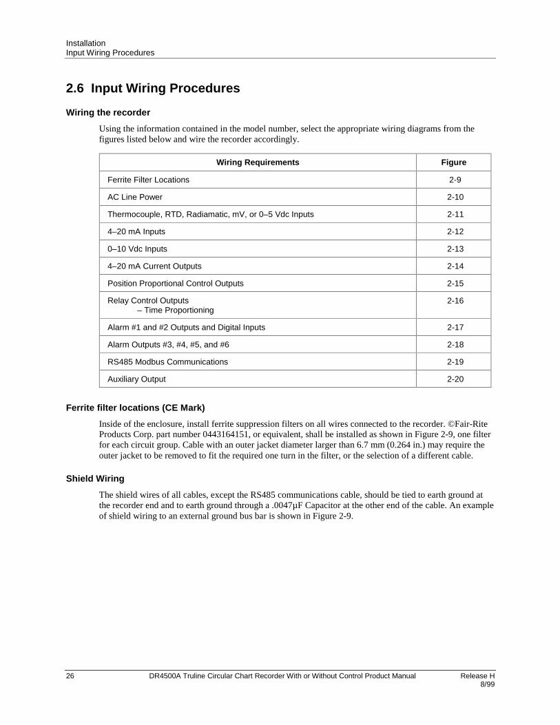
InstallationInput Wiring Procedures
26 DR4500A Truline Circular Chart Recorder With or Without Control Product Manual Release H 8/99
2.6 Input Wiring Procedures
Wiring the recorder
Using the information contained in the model number, select the appropriate wiring diagrams from thefigures listed below and wire the recorder accordingly.
Wiring Requirements Figure
Ferrite Filter Locations 2-9
AC Line Power 2-10
Thermocouple, RTD, Radiamatic, mV, or 0–5 Vdc Inputs 2-11
4–20 mA Inputs 2-12
0–10 Vdc Inputs 2-13
4–20 mA Current Outputs 2-14
Position Proportional Control Outputs 2-15
Relay Control Outputs– Time Proportioning
2-16
Alarm #1 and #2 Outputs and Digital Inputs 2-17
Alarm Outputs #3, #4, #5, and #6 2-18
RS485 Modbus Communications 2-19
Auxiliary Output 2-20
Ferrite filter locations (CE Mark)
Inside of the enclosure, install ferrite suppression filters on all wires connected to the recorder. ©Fair-RiteProducts Corp. part number 0443164151, or equivalent, shall be installed as shown in Figure 2-9, one filterfor each circuit group. Cable with an outer jacket diameter larger than 6.7 mm (0.264 in.) may require theouter jacket to be removed to fit the required one turn in the filter, or the selection of a different cable.
Shield Wiring
The shield wires of all cables, except the RS485 communications cable, should be tied to earth ground atthe recorder end and to earth ground through a .0047µF Capacitor at the other end of the cable. An exampleof shield wiring to an external ground bus bar is shown in Figure 2-9.

InstallationInput Wiring Procedures
Release H DR4500A Truline Circular Chart Recorder With or Without Control Product Manual 278/99
Trans- former
Mother PCB
Number 1 & 2 Alarm/ Digital Inputs
Control Loop 1 and Loop 2 Output Relays Alarm Relays
Current Output 1 & 2 Slidewire 1 & 2 Auxiliary Output
A.C. Main Digital Inputs 1 & 2
Transmitter Power
Inputs 1–4
Processor Board
Ferrite Filter
23685
Hex NutWasher
Use Cable fitting to support wiring and hold in place. Place the washer on the inside of the recorder between the case and the fastening nut to protect the recorder conductive case coating.
Shield Wiring
External Ground Bus Bar To Earth Ground
1 Recorder Grounding, rear of case - Use 3/4 inch braided copper conductor.
1
23
222
2
3
33
3
3
2
Cable Fitting
3 Ferrite Filter location - Cable with an outer jacket diameter larger than 6.7 mm (0.264 in.) may require the outer jacket to be removed to fit the required one turn in the filter, or the selection of a different cable.
2
RS485/422 Modbus Communications
3
Figure 2-9 Ferrite Filter Locations and Shield Wiring (CE Mark)
AC line power
Refer to Figure 2-10 and follow the procedure in Table 2-9 to connect the AC line power.
WARNING
Be sure that the line voltage is OFF before connecting the power wires to the recorderor personal injury could result.
This equipment is suitable for connection to 120/240 Vac, 50/60 Hz, power supply mains. It is the user’sresponsibility to provide a switch and non-time delay (North America), quick-acting, high breakingcapacity, Type F, (Europe) 1/2 A, 250 V fuse(s) or circuit-breaker as part of the installation. The switch orcircuit-breaker shall be located in close proximity to the recorder, within easy reach of the OPERATOR.The switch or circuit-breaker shall be marked as the disconnecting device for the recorder.

InstallationInput Wiring Procedures
28 DR4500A Truline Circular Chart Recorder With or Without Control Product Manual Release H 8/99
Table 2-9 AC Line Power Wiring
Step Action
1 Open the recorder door. Loosen the captive screw in the chart plate and swing the plate out.
2 Locate connector J10 on the bottom edge of the main printed circuit board. (Refer to Figure2-10.)
3 Remove the unwired plug from J10.
4 Run the power wires separately through second conduit from the right.
5 For CE Mark conformity, install the ferrite filter as shown in Figure 2-9.
6 Strip insulation from the end of each wire.
7 Loosen the screws in plug J10 terminals and position the plug as you would to plug it into J10.
8 Insert
• the green wire (G) into the first screw clamp from the right,
• the white wire (L2) into the second screw clamp from the right, and
• the black wire (L1) into the third screw clamp from the right.
Tighten the screws to secure the wires.
CAUTION To avoid damaging the recorder, be sure that you install the power wiresinto the correct screw clamps. Make sure the fuse block is installed properly for thegiven supply rating –– 120 or 240 Vac. The fuse is in the 120 Vac location from thefactory.
9 Make sure the fuse block is installed in the proper location. Refer to Figure 2-10 for fuse blocklocation.
• 120 Vac – Fuse block in location F2
• 240 Vac – Fuse block in location F1
10 Dress the wires as slack as possible. This keeps the noise signal on these wires frombypassing built-in suppression. Also, do not bundle any low level signal wires with the powerwires. Refer to Table 2-8 for permissible wire bundling.
• Refer to document 51-52-05-01 for additional information concerning noise interferenceprevention.
11 Insert the wired plug into J10.
WARNING Input line voltage will be present on the instrument ground plane if safetyground is not attached; personal injury and product damage could result.

InstallationInput Wiring Procedures
Release H DR4500A Truline Circular Chart Recorder With or Without Control Product Manual 298/99
#3#4 #2 #1
L1 L2
120 or 240 Vac
H N
PLUG J10
21410B
Fair-Rite P/N 0443164151 or equivalent
Required for CE Mark Conformity— Kit supplied Part No. 51197612-502, contains two ferrite filters. More than one kit may be supplied. Install inside of case. See Figure 2-9.
Required for CE Mark Conformity— 14 AWG Braided Wire to AC supply ground
Fuse Block on Main PC Board P/N51309355-tab
F1
240 Vac
F2
120 Vac
Figure 2-10 AC Line Power Wiring

InstallationInput Wiring Procedures
30 DR4500A Truline Circular Chart Recorder With or Without Control Product Manual Release H 8/99
Thermocouple, RTD, Radiamatic, mV, or 0-5 Vdc inputs
You can wire input 1, 2, 3, or 4 for thermocouple, RTD, Radiamatic, mV, or 0-5 Vdc actuations.
The polarity for inputs #1, #2, #3, and #4 is identical.
The prerequisites are:
• Model Number - Table 1 = 1XXX, X1XX, XX1X, XXX1
ATTENTION
For thermocouple or RTD inputs, calibrate the recorder to achieve the stated accuracy. Referto Section 7 – Input Calibration
Refer to Figure 2-11 and follow the procedure in Table 2-10 to wire Thermocouple, RTD, Radiamatic, mV,or 0–5 Vdc inputs.
Table 2-10 Thermocouple, RTD, Radiamatic, mV, or 0–5 Vdc Input Wiring
Step Action
1 Open the recorder door. Loosen the captive screw in the chart plate and swing the plate out.
2 Locate connector J2 on the printed circuit board for input 1 (refer to Figure 2-11).
3 Remove the unwired plug from J2.
4 Run the input wires through the desired knockout - DO NOT bundle them with the power wires.
5 For CE Mark conformity:
• Install the ferrite filter as shown in Figure 2-9.
• Install a .01µF capacitor across the J2 terminals and a .0047 µF capacitor at thesensor end of the input wiring as shown in Figure 2-11.
6 Locate jumper position MA/W1 and make sure the jumper is in the W1 position. (See Figure2-11 for the location.)
7 Locate jumper position W3 and make sure the jumper is in the proper position for your inputtype. (See Figure 2-11 for the jumper locations.)
8 Strip insulation from the end of each wire.
9 Loosen the screws in plug J2 terminals and position the plug as you would to plug it into J2.
10 Insert the wires into the appropriate screw clamps for the applicable input type. See Figure2-11 for specific input actuation plug wiring. Tighten the screws to secure the wires.
11 Insert the wired plug into J2.
12 Repeat steps 2 through 11 for input 2, 3, and 4 printed circuit boards as applicable.

InstallationInput Wiring Procedures
Release H DR4500A Truline Circular Chart Recorder With or Without Control Product Manual 318/99
Note: For T/C or RTD input, calibrate recorder to achieve stated accuracy. See Section 7 - Input Calibration.
+
-
Thermocouple
Plug J2
RTD
Plug J2
RTD
•
+
-
Radiamatic, mV, or 0-5 Vdc
Plug J2
mV or Volt source
21411B
T/C
#3#4 #2
#1Fair-Rite P/N 0443164151 or equivalent
Ferrite Filter
Capacitor Kit 51197755-001 Install capacitors as shown in figure.
Required for CE Mark Conformity Kit Part No. 51197612-502, contains two ferrite filters; Part No.51197612-508 contains 8 ferrite filters. Install inside of case. See Figure 2-9.
.0047Capacitor
Fµ
.0047Capacitor
Fµ
.01Capacitor
Fµ
Capacitors.01 Fµ
.01 Fµ
Capacitors.01 Fµ
Cable Shield
.0047Capacitor
Fµ
• Keep resistance of all wires equal Use 18 gauge copper wire for lengths up to 150 feet. For two wire RTD, jumper terminal 1 to 3.
•
•
Be sure that thermocouple extension wire matches thermocouple type
•
W1
MA
MA/W1 Jumper position on input board
T/C
RTD
T/C
RTD
Thermocouple Linear
MA
RTD
W3 Jumper Positions
TYPE W1/MA W3
T/C, Linear
RTD
W1
W1
T/C
RTD
Figure 2-11 Thermocouple, RTD, Radiamatic, mV, or 0–5 Vdc Input Wiring

InstallationInput Wiring Procedures
32 DR4500A Truline Circular Chart Recorder With or Without Control Product Manual Release H 8/99
4-20 mA inputs and transmitter power
You can wire input 1, 2, 3, or 4 for 4–20 mA actuations.
The polarity for inputs #1, #2, #3, and #4 is identical.
The prerequisites are:
• Model Number - Table 1 = 1XXX, X1XX, XX1X, XXX1
ATTENTION
Connector J11 on the main processor printed circuit board can be used to provide 24 Vdcpower to up to two field transmitters (without power) which are supplying the 4–20 mA inputsignals to the recorder (1.2W @ 24 Vdc = 50 mA available).
Refer to Figure 2-12 and follow the procedure in Table 2-11 to wire 4-20 mA inputs.
Table 2-11 4-20 mA Input Wiring
Step Action
1 Open the recorder door. Loosen the captive screw in the chart plate and swing the plate out.
2 Be sure that the jumper MA/W1 is installed in the position labeled “MA”; this connects aninternal 250-ohm resistor across the 4-20 mA input terminals on J2. Set jumper W3 accordingto your input type. (Refer to Figure 2-12 for location of jumper.)
3 Locate jumper position W3 and make sure the jumper is in the proper position for your inputtype (see Figure 2-12 for the location).
4 Locate connector J2 on the printed circuit board for input 1 (refer to Figure 2-12).
5 Remove the unwired plug from J2.
6 Run the input wires through the desired knockout - DO NOT bundle them with the power wires.
7 For CE Mark conformity, install the ferrite filter as shown in Figure 2-9 and the capacitors asshown in Figure 2-12.
8 Strip insulation from the end of each wire.
9 Loosen the screws in plug J2 terminals and position the plug as you would to plug it into J2.
10 • For transmitters with power:
Insert the wires into the appropriate screw clamps and tighten the screws to secure thewires.
ATTENTION The DR4500A Recorder inputs are protected from overvoltage by aprotection diode. The wake-up pulse on the ST3000 may not be recognized by the transmitterdue to this clamping action. It may be necessary to add 100 ohms of additional loop resistanceso the transmitter and SFC can communicate.
• For transmitters which require power:
Remove the unwired plug from J11 then wire the transmitter power to J11 and theinput to J2. Tighten the screws in the plugs to secure the wires.
11 Insert the wired plug into J2 and J11 as applicable.
12 Repeat steps 2 through 11 for input 2, 3, and 4 printed circuit boards as applicable.

InstallationInput Wiring Procedures
Release H DR4500A Truline Circular Chart Recorder With or Without Control Product Manual 338/99
VIEW A - From transmitter with power
#3#4 #2 #1
ATTENTION The DR4500A Recorder inputs are protected from overvoltage by a protection diode. The wake up pulse on the ST3000 may not be recognized by the transmitter due to this clamping action. It may be necessary to add 100 ohms of additional loop resistance so the transmitter and SFC can communicate.
Fair-Rite P/N 0443164151 or equivalent
Ferrite Filter
+4-20 mA
Plug J2
VIEW B - From transmitter receiving 24Vdc power from recorder
+_
Xmtr
Transmitter power (24 Vdc)
Plug J11
21412B
_
Ferrite filter
4-20 mA
Plug J2
+
_
4 - 20 mA source
Capacitor Kit 51197755-001 Install capacitors as shown in figure.
Required for CE Mark Conformity Kit Part No. 51197612-502, contains two ferrite filters; Part No.51197612-508 contains 8 ferrite filters. Install inside of case. See Figure 2-9.
Cable Shield
.0047 µFCapacitor
+
_
Cable Shield
.0047 µFCapacitor
.01 µFW1
MA
MA/W1 Jumper position on input board
T/C
RTDLinear/MA
W3 Jumper Positions
TYPE W1/MA W3
T/C4-20mA M/A
Figure 2-12 4-20 mA Input Wiring
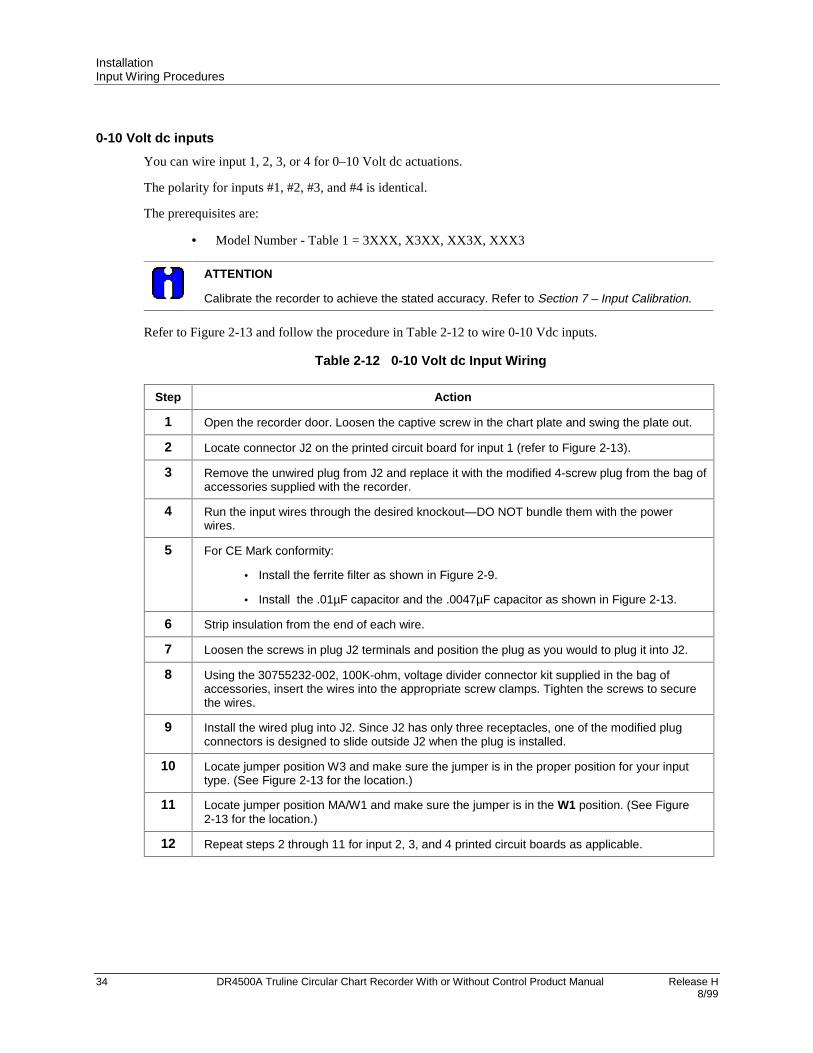
InstallationInput Wiring Procedures
34 DR4500A Truline Circular Chart Recorder With or Without Control Product Manual Release H 8/99
0-10 Volt dc inputs
You can wire input 1, 2, 3, or 4 for 0–10 Volt dc actuations.
The polarity for inputs #1, #2, #3, and #4 is identical.
The prerequisites are:
• Model Number - Table 1 = 3XXX, X3XX, XX3X, XXX3
ATTENTION
Calibrate the recorder to achieve the stated accuracy. Refer to Section 7 – Input Calibration.
Refer to Figure 2-13 and follow the procedure in Table 2-12 to wire 0-10 Vdc inputs.
Table 2-12 0-10 Volt dc Input Wiring
Step Action
1 Open the recorder door. Loosen the captive screw in the chart plate and swing the plate out.
2 Locate connector J2 on the printed circuit board for input 1 (refer to Figure 2-13).
3 Remove the unwired plug from J2 and replace it with the modified 4-screw plug from the bag ofaccessories supplied with the recorder.
4 Run the input wires through the desired knockout—DO NOT bundle them with the powerwires.
5 For CE Mark conformity:
• Install the ferrite filter as shown in Figure 2-9.
• Install the .01µF capacitor and the .0047µF capacitor as shown in Figure 2-13.
6 Strip insulation from the end of each wire.
7 Loosen the screws in plug J2 terminals and position the plug as you would to plug it into J2.
8 Using the 30755232-002, 100K-ohm, voltage divider connector kit supplied in the bag ofaccessories, insert the wires into the appropriate screw clamps. Tighten the screws to securethe wires.
9 Install the wired plug into J2. Since J2 has only three receptacles, one of the modified plugconnectors is designed to slide outside J2 when the plug is installed.
10 Locate jumper position W3 and make sure the jumper is in the proper position for your inputtype. (See Figure 2-13 for the location.)
11 Locate jumper position MA/W1 and make sure the jumper is in the W1 position. (See Figure2-13 for the location.)
12 Repeat steps 2 through 11 for input 2, 3, and 4 printed circuit boards as applicable.

InstallationInput Wiring Procedures
Release H DR4500A Truline Circular Chart Recorder With or Without Control Product Manual 358/99
#3#4 #2 #1
Fair-Rite P/N 0443164151 or equivalent
Ferrite Filter
0 - 10 Vdc source
NOTE: Calibrate recorder to achieve stated accuracy. See Section 7 - Input Calibration.
21413BCapacitor Kit 51197755-001 Install capacitors as shown in figure.
Required for CE Mark Conformity Kit Part No. 51197612-502, contains two ferrite filters; Part No.51197612-508 contains 8 ferrite filters. Install inside of case. See Figure 2-9.
+
Plug J2 (modified)
_
100K
100K
Cable Shield
.0047 µFCapacitor
.01 µF
W1
MA
MA/W1 Jumper position on input board
T/C
RTDLinear/MA
W3 Jumper Positions
TYPE W1/MA W3
Linear W1 T/C
Figure 2-13 0-10 Volt dc Input Wiring

InstallationOutput Wiring Procedures
36 DR4500A Truline Circular Chart Recorder With or Without Control Product Manual Release H 8/99
2.7 Output Wiring Procedures
4-20 mA control output wiring
You can wire control output 1 or 2 for 4-20 mA output.
The prerequisites are:
• Model Number - Table 2 = 10, 40, 44, 60, or 66
Refer to Figure 2-14 and follow the procedure in Table 2-13 to wire 4-20 mA control outputs.
Table 2-13 4-20 mA Control Output Wiring
Step Action
1 Open the recorder door. Loosen the captive screw in the chart plate and swing the plate out.
2 Locate connector J1 near the top of the control output #1 or #2 printed circuit board (refer toFigure 2-14 for location).
3 Remove the unwired plug from J1.
4 Run the output wires through the desired knockout.
5 For CE Mark conformity, install the ferrite filter as shown in Figure 2-9 and the .0047µFcapacitor as shown in Figure 2-14.
6 Strip insulation from the end of each wire.
7 Loosen the screws in plug J1 terminals and position the plug as you would to plug it into J1.
8 Observing the polarity, insert the wires into the appropriate screw clamps as shown (refer toFigure 2-14). Tighten the screws to secure the wires.
9 Install the wired plug into J1.
10 Locate jumper position W6/W7 on the bottom left portion of the board. Make sure W7 positionis selected for 4-20 mA output.
11 Repeat steps 2 through 10 for control output #2 printed circuit board as applicable.
TIP
The 4-20 mA output can be used as a retransmission output if it is not used as a controloutput.

InstallationOutput Wiring Procedures
Release H DR4500A Truline Circular Chart Recorder With or Without Control Product Manual 378/99
#3#4 #2 #1
+
_
Controller load 0-1000 ohms
4-20 mA output
Plug J1
21414
Control Output #1 PCB
Control Output #2 PCB
Fair-Rite P/N 0443164151 or equivalent
Ferrite Filter
W6W7
Control Output #1-2 PCB Current Output Select Jumper
W7 = Relay or Current Output
Capacitor Kit 51197755-001 Install capacitors as shown in figure.
Required for CE Mark Conformity Kit Part No. 51197612-502, contains two ferrite filters; Part No.51197612-508 contains 8 ferrite filters. Install inside of case. See Figure 2-9.
Cable Shield
.0047 FCapacitor
Figure 2-14 4-20 mA Control Output Wiring

InstallationOutput Wiring Procedures
38 DR4500A Truline Circular Chart Recorder With or Without Control Product Manual Release H 8/99
Position proportional or 3-position step control output wiring
You can wire control output 1 or 2 for position proportional or 3 position step output.
The prerequisites are:
• Model Number Key = DR45AT
• Model Number - Table 2 = 10, 40, or 44
Refer to Figure 2-15 and follow the procedure in Table 2-14 to wire position proportional or 3 position stepcontrol outputs.
ATTENTION
Be sure to calibrate the position proportional control output so that the increase and decreaserelays operate properly with respect to the position of the external feedback slidewire. Refer toSection 8 - Output Calibration in this manual.
Slidewire input is not required for 3 position step control but can be used for motor position indication.
Table 2-14 Position Proportional Control Output Wiring
Step Action
1 Open the recorder door. Loosen the captive screw in the chart plate and swing the plate out.
2 Locate connector J2 and J5 on the control output #1 printed circuit board (refer to Figure 2-15for location).
3 Locate jumper positions W2/W3 and W4/W5 below connector J5 on the printed circuit board.Remove plug-in output #1 printed circuit board for better access to the jumpers. Be sure to tagand remove all the plug connections to the printed circuit board before removing it. Position thejumpers as shown in Figure 2-15 for desired relay contact action. Locate jumper positionW6/W7 on the bottom left portion of the board. Make sure position W6 is selected for positionproportioning, then reinstall the printed circuit board.
4 Run the feedback slidewire (not required for 3 position step) and motor drive wires through thedesired knockouts.
5 For CE Mark conformity:
• install the ferrite filter as shown in Figure 2-9
• install the shield capacitors as shown in Figure 2-15.
6 Strip insulation from the end of each wire.
7 Loosen the screws in plug J2 terminals and position the plug as you would to plug it into J2.
8 Insert the wires from the motor’s feedback slidewire into the appropriate screw clamps asshown (refer to Figure 2-15). Tighten the screws to secure the wires.
9 Loosen the screws in plug J5 terminals and position the plug as you would to plug it into J5.
10 Insert the wires for the motor into the appropriate screw clamps as shown (refer to Figure2-15). Tighten the screws to secure the wires.
11 Install the wired plug into J2 and J5, as applicable.
12 Repeat steps 2 through 11 for Control Output #2 printed circuit boards as applicable.

InstallationOutput Wiring Procedures
Release H DR4500A Truline Circular Chart Recorder With or Without Control Product Manual 398/99
21415
Fair-Rite P/N 0443164151 or equivalent
Ferrite Filter
Control output #1-2 PCB
Relay No. 1 W2 = N.O. contact W3 = N.C. contact Relay No. 2 W4 = N.O. contact W5 = N.C. contactW5
W4
W3
W2
W6W7
1
2
3
Plug J2
OPEN
CLOSED
Motor’s feedback slidewire 100to 1000(Not required for Three Position Step Control)
#3#4 #2 #1Control output #2 PCB
Control output #1 PCB
Plug J5
N
H
Motor power supply
CLOSED (CCW)
OPEN (CW)
Capacitor Kit 51197755-001 Install capacitors as shown in figure.
Required for CE Mark Conformity Kit Part No. 51197612-502, containstwo ferrite filters; Part No.51197612-508 contains 8 ferrite filters.Install inside of case. See Figure 2-9.
.0047 FCapacitor
Relay 2
Relay 1
.0047 FCapacitor
W6 = Position Proportional Output
Cable Shield
Figure 2-15 Position Proportional Control Output or Three Position Step Wiring

InstallationOutput Wiring Procedures
40 DR4500A Truline Circular Chart Recorder With or Without Control Product Manual Release H 8/99
Relay control output wiring
You can wire control output 1 or 2 for relay output including Time proportional and 3 position stepapplications.
The prerequisites are:
• Model Number - Table 2 = 10, 40, 60, 11, 44, 66
Refer to Figure 2-16 and follow the procedure in Table 2-15 to wire relay control outputs.
ATTENTION
Relay #2 is used for time proportional control. Relay 2 can also be used for 3 position stepcontrol (see Figure 2-15).
Table 2-15 Relay Control Output Wiring
Step Action
1 Open the recorder door. Loosen the captive screw in the chart plate and swing the plate out.
2 Locate connector J5 on the control output #1 printed circuit board (refer to Figure 2-16 forlocation).
3 Remove the unwired plug from J5.
4 Locate jumper positions W2/W3 and W4/W5 below connector J5 on the printed circuit board.Remove plug-in output #1 printed circuit board for better access to the jumpers. Be sure to tagand remove all the plug connections to the printed circuit board before removing it. Position thejumpers as shown in Figure 2-16 for desired relay contact action. Locate jumper positionW6/W7 on the bottom left portion of the board. Make sure W7 position is selected for relaycontrol output, then reinstall the printed circuit board.
5 Run the relay load wires through the desired knockouts.
6 For CE Mark conformity: - install the ferrite filter as shown in Figure 2-9. - install the shield capacitor as shown in Figure 2-16.
7 Strip insulation from the end of each wire.
8 Loosen the screws in plug J5 terminals and position the plug as you would to plug it into J5.
9 Insert the relay wires and relay power into the appropriate screw clamps for single or duplexaction as shown (refer to Figure 2-16); tighten the screws to secure the wires.
10 Install the wired plug into J5.
11 Repeat steps 2 through 10 for control output #2 printed circuit boards as applicable.
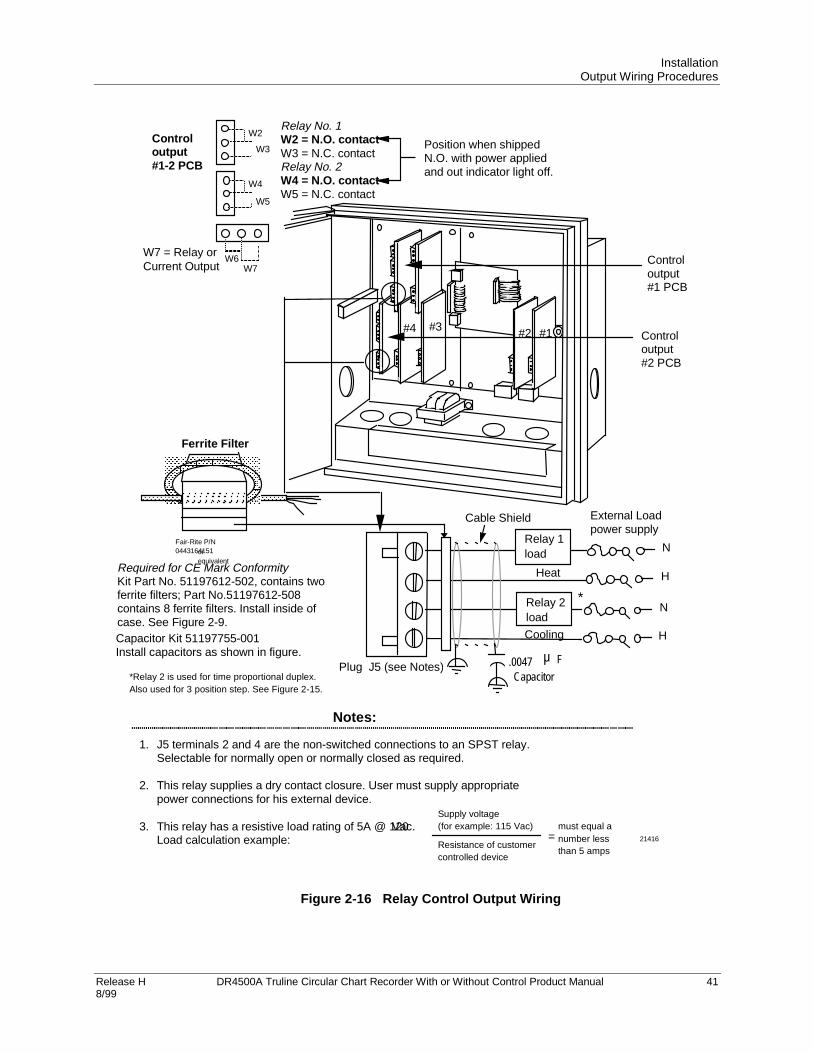
InstallationOutput Wiring Procedures
Release H DR4500A Truline Circular Chart Recorder With or Without Control Product Manual 418/99
W5
W4
W3
W2
W6W7
Relay No. 1W2 = N.O. contactW3 = N.C. contactRelay No. 2W4 = N.O. contactW5 = N.C. contact
21416
Position when shippedN.O. with power appliedand out indicator light off.
Notes:
1.
2.
3.
J5 terminals 2 and 4 are the non-switched connections to an SPST relay.Selectable for normally open or normally closed as required.
This relay supplies a dry contact closure. User must supply appropriatepower connections for his external device.
This relay has a resistive load rating of 5A @ 120 Vac.Load calculation example:
Supply voltage(for example: 115 Vac)
Resistance of customercontrolled device
=must equal anumber lessthan 5 amps
#3#4 #2 #1
N
H
Plug J5 (see Notes)
Relay 2load
H
N
Relay 1load
External Loadpower supply
*Relay 2 is used for time proportional duplex.Also used for 3 position step. See Figure 2-15.
Heat
Cooling
*
Controloutput#1 PCB
Controloutput#2 PCB
Fair-Rite P/N0443164151or
equivalent
Ferrite Filter
Controloutput#1-2 PCB
Cable Shield
.0047Capacitor
FµCapacitor Kit 51197755-001Install capacitors as shown in figure.
Required for CE Mark ConformityKit Part No. 51197612-502, contains twoferrite filters; Part No.51197612-508contains 8 ferrite filters. Install inside ofcase. See Figure 2-9.
W7 = Relay orCurrent Output
Figure 2-16 Relay Control Output Wiring

InstallationOption Wiring Procedures
42 DR4500A Truline Circular Chart Recorder With or Without Control Product Manual Release H 8/99
2.8 Option Wiring Procedures
Alarm output and digital input wiring
You can wire #1 and #2 Alarm Outputs and Digital Inputs.
The prerequisites are:
• Model Number - Table 3 = XX1
Refer to Figure 2-17 and follow the procedure in Table 2-16 to wire alarm outputs or digital inputs.
The alarm output is a dry contact closure.
Table 2-16 Alarm Output or Digital Input Wiring
Step Action
1 Open the recorder door. Loosen the captive screw in the chart plate and swing the plate out.
2 Locate connector J3 and J4 on the alarm output/digital input printed circuit board (refer toFigure 2-17 for location).
3 Remove the unwired plug from J3.
4 Run the digital input wires through the desired knockout.
5 For CE Mark conformity, install the ferrite filter as shown in Figure 2-9.
6 Strip insulation from the end of each wire.
7 Loosen the screws in plug J3 terminals and position the plug as you would to plug it into J3.
8 Insert the wires for the digital inputs into the appropriate screw clamps as shown (refer toFigure 2-17). Note that you can wire the contacts in an and /or fashion, so that both contactsor either contact initiates the configured action. Tighten the screws to secure the wires.
9 Install the wired plug into J3.
10 Remove the unwired plug from J4.
11 Run the alarm output wires through the desired knockout.
12 For CE Mark conformity:
• install the ferrite filter as shown in Figure 2-9
• install the shield capacitors as shown in Figure 2-17.
13 Strip insulation from the end of each wire.
14 Loosen the screws in plug J4 terminals and position the plug as you would to plug it into J4.
15 Insert the wires for the alarm devices into the appropriate screw clamps as shown (refer toFigure 2-17). Tighten the screws to secure the wires.
16 Locate the jumper positions W1/W2 and W3/W4 on the printed circuit board. Reposition thejumpers as shown in Figure 2-17for the desired relay control action. The recorder is shippedwith the W1 and W3 in N.C. positions.
17 Install the wired plug into J4.

InstallationOption Wiring Procedures
Release H DR4500A Truline Circular Chart Recorder With or Without Control Product Manual 438/99
21417
Notes:1. 2. 3.
J4 terminals 2 and 4 are the non-switched connections to an SPST relay. Selectable for normally open or normally closed as required. This relay supplies a dry contact closure. User must supply appropriate power connections for his external device. This relay has a resistive load rating of 1A @ 120 Vac. Load calculation example:
Fair-Rite P/N 0443164151 or equivalent
Ferrite Filter
Alarm No. 1 W3 = N.C. contact W4 = N.O. contact Alarm No. 2 W1 = N.C. contact W2 = N.O. contact
W4
W3
W2
W1
Alarm outputs
Plug J4 (see Notes)
Position when shipped N.C. with power off or Alarm indicator light on.
#3#4 #2 #1
External Load Power Supply
Alarm #1 Relay Load
Alarm #2 Relay Load
Plug J3
Digital inputs
PIN 3 - 2nd Control Loop + Digital 2
PIN 2 - 1st Control Loop + Digital 1
PIN 1 - Recorder Supplied Voltage Source for Digital Inputs
Supply voltage (for example: 115 Vac)
Resistance of customer controlled device
=must equal a number less than 1 amps
Cable Shield
.0047 µF Capacitor
Capacitor Kit 51197755-001 Install capacitors as shown in figure.
Required for CE Mark Conformity Kit Part No. 51197612-502, contains two ferrite filters; Part No.51197612-508 contains 8 ferrite filters. Install inside of case. See Figure 2-9.
Cable Shield
.0047 µF Capacitor
Figure 2-17 Alarm Output or Digital Input Wiring

InstallationOption Wiring Procedures
44 DR4500A Truline Circular Chart Recorder With or Without Control Product Manual Release H 8/99
Additional alarm wiring information
The DR4500 has the ability to provide for Alarm outputs 3, 4, 5, and 6.
Follow the procedures listed below to wire No. 3 and No. 4 Alarm Outputs and No. 5 and No. 6 AlarmOutputs.
Alarms 3 and 4 output wiring
You can wire #3 and #4 Alarm Outputs.
The prerequisites are:
• Model Number - Model Table 2 = 1X, 4X, 6X*
*If control output is 4-20 mA, then the relays on the control card are available for use asalarms on all models except DR45AH/AS/AP models.
Refer to Figure 2-18 and follow the procedure in Table 2-17 to wire Alarm 3 and Alarm 4 outputs.
Table 2-17 Alarm 3 and Alarm 4 Output Wiring
Step Action
1 Open the recorder door. Loosen the captive screw in the chart plate and swing the plate out.
2 Locate connector J5 on the 4-20 mA control output printed circuit board to wire relays #3 and#4. Refer to Figure 2-18 for location.
3 Remove the unwired plug from J5.
4 Locate jumper position W2/W3 and W4/W5 below connector J5 on the printed circuit board.Note that you may want to remove the plug-in output printed circuit board for better access tojumpers. Be sure to tag and remove all the plug connections to the printed circuit boardsbefore removing it. Position the jumpers as shown for the desired relay contact action andreinstall the printed circuit board.
5 Run the alarm output wires through the desired knockout.
6 For CE Mark conformity:
• install the ferrite filter as shown in Figure 2-9
• install the capacitors as shown in Figure 2-18
7 Strip insulation from the end of each wire.
8 Loosen the screws in plug J5 terminals and position the plug as you would to plug it into J5.
9 Insert the wires for the alarm devices into the appropriate screw clamps as shown. Refer toFigure 2-18. Tighten the screws to secure the wires.
10 Install the wired plug into J5.

InstallationOption Wiring Procedures
Release H DR4500A Truline Circular Chart Recorder With or Without Control Product Manual 458/99
Alarm 5 and 6 output wiring
You can wire #5 and #6 Alarm outputs.
The prerequisites are:
• Model Number - Model Table 2 = X1, X4, X6*
*If control output is 4-20 mA, then the relays on the control card are available for use asalarms on all models except DR45AH/AS/AP models.
Refer to Figure 2-18 and follow the procedure in Table 2-18 to wire Alarm 5 and Alarm 6 outputs.
Table 2-18 Alarm 5 and Alarm 6 Output Wiring
Step Action
1 Open the recorder door. Loosen the captive screw in the chart plate and swing the plate out.
2 Locate connector J5 on the 4-20 mA control output printed circuit board to wire relays #5 and#6. Refer to Figure 2-18 for location.
3 Remove the unwired plug from J5.
4 Locate jumper position W2/W3 and W4/W5 below connector J5 on the printed circuit board.Note that you may want to remove the plug-in output printed circuit board for better access tojumpers. Be sure to tag and remove all the plug connections to the printed circuit boardsbefore removing it. Position the jumpers as shown for the desired relay contact action andreinstall the printed circuit board.
5 Run the Alarm output wires through the desired knockout.
6 For CE Mark conformity:
• install the ferrite filter as shown in Figure 2-9
• install the capacitors as shown in Figure 2-18
7 Strip insulation from the end of each wire.
8 Loosen the screws in plug J5 terminals and position the plug as you would to plug it into J5.
9 Insert the wires for the alarm devices into the appropriate screw clamps as shown. Refer toFigure 2-18. Tighten the screws to secure the wires.
10 Install the wired plug into J5.

InstallationOption Wiring Procedures
46 DR4500A Truline Circular Chart Recorder With or Without Control Product Manual Release H 8/99
Wiring for alarm outputs #3, 4, 5, and 6
Plug J5
4 - 20 mA control output and no. 3 & 4 alarm outputs PCB
Alarm No. 4 W4 = N.O. contact W5 = N.C. contact
W3 W2
W5 W4
Alarm No. 3 W2 = N.O. contact W3 = N.C. contact
#3#4 #2 #1
21466
No. 5 & 6 Alarm outputs PCB
W3 W2
W5 W4
Alarm No. 5 W2 = N.O. contact W3 = N.C. contact Alarm No. 6 W4 = N.O. contact W5 = N.C. contact
Alarm #5 Relay Load
Alarm #6 Relay Load
Fair-Rite P/N 0443164151 or equivalent
Ferrite Filter
Ferrite filter
Plug J5
Alarm #3 Relay Load
Alarm #4 Relay Load
External Load Power Supply
Ferrite filter
External Load Power Supply
.0047 F
Cable Shield
Capacitor
.0047 F
Cable Shield
Capacitor
Capacitor Kit 51197755-001 Install capacitors as shown in figure.
Required for CE Mark Conformity Kit Part No. 51197612-502, contains two ferrite filters; Part No.51197612-508 contains 8 ferrite filters. Install inside of case. See Figure 2-9.
Figure 2-18 Alarm outputs #3, 4, 5, and 6 wiring

InstallationOption Wiring Procedures
Release H DR4500A Truline Circular Chart Recorder With or Without Control Product Manual 478/99
RS485 Modbus communications wiring
RS485 Modbus Communications is an option available on the DR4500A recorder.
The prerequisites are:
• Model Key Number - All models except DR45AH/AP/AS
• Model Number - Table 3 = 3XX or 4XX
Refer to Figure 2-19 and follow the procedure in Table 2-19 to wire the RS485 Modbus communicationsoption.
Table 2-19 RS485 Modbus Communications Wiring
Step Action
1 Open the recorder door. Loosen the captive screw in the chart plate and swing the plate out.
2 Locate connector J3 on the RS485 Modbus communications option printed circuit board (referto Figure 2-19 for location).
3 Remove the unwired plug from J3.
4 Run the communications option wires through the desired knockout.
5 For CE Mark conformity
• Install the ferrite filter as shown in Figure 2-9.
• Refer to Figure 2-19 for shield information.
6 Strip insulation from the end of each wire.
7 Loosen the screws in plug J3 terminals and position the plug as you would to plug it into J3.
8 Insert the wires for the communications option into the appropriate screw clamps as shown(refer to Figure 2-20). Tighten the screws to secure the wires.
9 Install the wired plug J3 into J3 connector on the communications board.
REFERENCE
Refer to Documents 51-52-25-66 and 51-52-25-69 for a complete description of RS485Modbus Communications Option.

InstallationOption Wiring Procedures
48 DR4500A Truline Circular Chart Recorder With or Without Control Product Manual Release H 8/99
#3#4 #2 #1
Communications master
Plug J3
SHLDTx–/ Rx–
Tx+/ Rx+
To other communications instruments (Maximum 15)
Optional communication
21418G
Fair-Rite P/N 0443164151 or equivalent
Required for CE Mark Conformity— Kit supplied Part No. 51197612-502, contains two ferrite filters. More than one kit may be supplied. Install inside of case. See Figure 2-9. Communication wire must be Alpha XTRA Guard I Cable (Alpha P/N 5121C)
Ferrite Filter
120 Ohm Resistor
See Note 1
See Note 2
Place 120 Ohm Resistor on last device, between Tx+/Rx+ and Tx–/Rx–.
Notes:
1. The shield of the RS485 Modbus Communications cable is not connected at the recorder end and should not extend into the recorder enclosure. The shield of the communication cable should be connected to earth ground at the farthest end on the cable. 2. For non-CE Mark applications, use shielded twisted pair cables (Belden 4271 Twinax or equivalent).
Figure 2-19 RS485 Modbus Communications Wiring

InstallationOption Wiring Procedures
Release H DR4500A Truline Circular Chart Recorder With or Without Control Product Manual 498/99
4-20 mA auxiliary output wiring
You can wire an auxiliary output for 4–20 mA.
The prerequisites are:
• Model Number - Table 3 = 1XX or 4XX
Refer to Figure 2-20 and follow the procedure in Table 2-20 to wire 4–20 mA auxiliary output.
Table 2-20 4-20 mA Auxiliary Output Wiring
Step Action
1 Open the recorder door. Loosen the captive screw in the chart plate and swing the plate out.
2 Locate connector J2 near the bottom of the auxiliary output printed circuit board (refer toFigure 2-20 for location).
3 Remove the unwired plug from J2.
4 Run the output wires through the desired knockout.
5 For CE Mark conformity, install the ferrite filter as shown in Figure 2-9.
6 Strip insulation from the end of each wire.
7 Loosen the screws in plug J2 terminals and position the plug as you would to plug it into J2.
8 Observing the polarity, insert the wires into the appropriate screw clamps as shown (refer toFigure 2-20). Tighten the screws to secure the wires.
9 Install the wired plug into J2.
ATTENTION
Be sure that the 4-20 mA auxiliary output is aligned. Refer to subsection 8.4 Auxiliary OutputCalibration.
TIP
The 4-20 mA output on the control output board can also be set up for an Auxiliaryretransmission output if it is not being used for a control output. This requires model selectionoption Table II = 10, 40, 44, 60, 66.
TIP
Auxiliary output 2 and Auxiliary output 3 use Control current output 1 and Control currentoutput 2 if Control “OUT ALG” is not set to “CURRENT”.

InstallationOption Wiring Procedures
50 DR4500A Truline Circular Chart Recorder With or Without Control Product Manual Release H 8/99
#3#4 #2 #1
+
_
4-20 mA auxiliary output
Plug J222841G
Auxiliary Output PCB
Fair-Rite P/N 0443164151 or equivalent
Ferrite Filter
.0047 F Capacitor
Controller load 0-1000 ohms
Capacitor Kit 51197755-001 Install capacitors as shown in figure.
Required for CE Mark Conformity Kit Part No. 51197612-502, contains two ferrite filters; Part No.51197612-508 contains 8 ferrite filters. Install inside of case. See Figure 2-9.
Figure 2-20 4-20 mA Auxiliary Output Wiring

InstallationLockout Switch Configuration
Release H DR4500A Truline Circular Chart Recorder With or Without Control Product Manual 518/99
2.9 Lockout Switch Configuration
Introduction
The configuration can be locked using S1 switch located next to the microprocessor U17 on the mainprinted circuit board.
Restrictions based on lockout switch position
Figure 2-21 shows the location of the S1 lockout switch on the main printed circuit board.
When the lockout switch is OFF (Down—Configure):
• You can view and change all applicable operating parameters as described in Section 4 –Configuration Parameter Definitions.
When the lockout switch is ON (Up—Locked):
• Most parameters for the recorder are locked and the parameters may not be changed except forTuning 1 and Tuning 2 parameters and adjustments to time/date/day/year.
U17
S1
U19
J17
R47
C55
C56Y2
R45
R43
R42
C50UP (ON) Locked
DOWN (OFF) Configure
Main Printed Wiring Board (Right Side)
S1 Lockout Switch
22709
Figure 2-21 S1 Lockout Switch Location
ATTENTION
Lockout can also be configured under set up group “LOCKOUT”. See Subsection 3.21.
This feature also includes the special screw and plate that provide the lead seal capability forsealing the chart plate. This feature is normally used with DR45AH model recorders.

Release H DR4500A Truline Circular Chart Recorder With or Without Control Product Manual 528/99

Release H DR4500A Truline Circular Chart Recorder With or Without Control Product Manual 538/99
3. Configuration
3.1 Overview
Introduction
Configuration is a dedicated operation where you use straightforward keystroke sequences to select andestablish (configure) pertinent control data best suited for your application.
What’s in this section?
The table below lists the topics that are covered in this section.
Topic See Page
3.1 Overview 53
3.2 Configuration Prompts 55
3.3 How to Get Started 58
3.4 Configuration Tips 59
3.5 Configuration Procedure 60
3.6 Input Set Up Group 62
3.7 Pen Set Up Group 64
3.8 Chart Set Up Group 65
3.9 Time Set Up Group 67
3.10 Totalizer Set Up Group 68
3.11 Input Algorithm Set Up Group 69
3.12 Control Set Up Group 70
3.13 Tuning Parameters Set Up Group 72
3.14 SP Ramp Set Up Group 73
3.15 Timer Set Up Group 74
3.16 Alarms Set Up Group 75
3.17 Auxiliary Output Set Up Group 77
3.18 Modbus Communications Set Up Group 78
3.19 Options Set Up Group 79
3.20 Event Message 80
3.21 Lockout Set Up Group 83
3.22 Adjust Printing 84
3.23 Configuration Record Sheet 85

ConfigurationOverview
54 DR4500A Truline Circular Chart Recorder With or Without Control Product Manual Release H 8/99
Prompts
To assist you in the configuration process, there are prompts that appear in the upper and lower displays.These prompts let you know what group of configuration data (set up prompts) you are working with andalso the specific parameters (function prompts) associated with each group.
Figure 3-1 shows an overview of the prompt hierarchy.

ConfigurationConfiguration Prompts
Release H DR4500A Truline Circular Chart Recorder With or Without Control Product Manual 558/99
3.2 Configuration Prompts
Diagram: prompt hierarchy
Figure 3-1 shows an overview of the DR4500A Set Up prompts and their associated Function prompt - readfrom left to right.
Figure 3-1 DR4500A Prompt Hierarchy
Set Up Group Function Prompts
FO RESET RESET FO Only with key number DR45AR, see Appendix A
INPUT 1 ENABLE DECIMAL UNITS ENGUNITS IN1 TYPE XMITTER IN1 HI
IN1 LO CUTOFF 1 INPTCOMP FILTER1 BURNOUT EMISSIV
INPUT 2INPUT 3INPUT 4
Same as INPUT 1
PEN 1 ENABLE PEN 1 IN CHART1HI CHART1LO PEN1ON PEN1OFF MAJORDIV
MINORDIV RNG1TAG
PEN 2PEN 3PEN 4
Same as PEN 1
CHART CHRTSPD HOUR/REV TIME DIV MINORDIV CONTINUE CHARTNAM HEADER
REM CHRT WAKE MIN WAKE HR WAKE DAY WAKE MON
TIME MINUTES HOURS DAY MONTH YEAR DAY
TOTAL 1 (Value) RSET TOT TOTAL 1 TOTAL EU RATE SCALER RSETABLE
TOTAL 2 Same as TOTAL 1
INP ALG INP ALG COEFF PV HIGH PV LOW RATIO A BIAS A RATIO B
BIAS B RATIO C BIAS C POLYNOM C0 VALUE C2x10-1 C3x10-3
C4x10-5 C5x10-7

ConfigurationConfiguration Prompts
56 DR4500A Truline Circular Chart Recorder With or Without Control Product Manual Release H 8/99
Set Up Group Function Prompts
CONTROL 1 ENABLE PID SETS SW VALUE SP SOURC RATIO BIAS SP TRACK
POWER UP PWR OUT SP HILIM SP LOLIM ACTION OUT HILIM OUT LOLIM
DROPOFF DEADBAND OUT HYST FAILSAFE REM SW MAN KEY PBorGAIN
MINorRPM CONT1ALG OUT1ALG 4-20 RNG
CONTROL 2 Same as CONTROL 1
TUNING 1 FUZZY ACCUTUNE AT ERR PROP BDor
GAIN
RATE MIN RSET MINor
RSET RPM
MAN RSET
PROP BD2or
GAIN 2
RATE2MIN RSET2MINor
RSET2RPM
CYC SEC CYC2SEC
TUNING 2 Same as TUNING 1
SP RAMP1 ENABLE SP RAMP TIME MIN FINAL SP
SP RATE EU/HR UP EU/HR DN
SP PROG RECYCLES SOAK DEV PROFILE STATE RECOVERY
PROG END
SP RAMP2 Same as SP RAMP1
SPP SEGS PRx STRT PRx END RAMPUNIT SYNC 1+2 SEGxRAMP SEGx SP SEGxTIME
SPP EVNT SEGx EV
TIMER TIMER PERIOD START LDISPLAY RSET INCRMENT
ALARM 1 A1S1 VAL A1S2 VAL A1S1TYPE A1S2TYPE A1S1 H L A1S1 EV A1S1SCAL
A1S2 H L A1S2 EV A1S2SCAL AL1 HYST
ALARM 2ALARM 3ALARM 4ALARM 5ALARM 6
Same as ALARM 1

ConfigurationConfiguration Prompts
Release H DR4500A Truline Circular Chart Recorder With or Without Control Product Manual 578/99
Set Up Group Function Prompts
AUX OUT AUX OUT 4 mA VAL 20mA VAL AUX OUT 2 4 mA VAL 20mA VAL AUX OUT 3
4mA VAL 20 mA VAL
COMM ComSTATE Com ADDR BAUD XMT DLAY
OPTIONS REJ FREQ HF REJ RELHUMID ATMPRES DEVIATION DEVSETPT SCROLL
GRANDTOT If key number is DR45AR, see Appendix A for Fo calculation prompts.
EVNT MSG EVENT 1 MESSAGE1 POSITION1 EVENT 2 MESSAGE2 POSITION2 EVENT 3
MESSAGE3 POSITION3 EVENT 4 MESSAGE4 POSITION4 EVENT 5 MESSAGE5
POSITION5 EVENT 6 MESSAGE6 POSITION6
LOCKOUT PASSWORD LOCKOUT CHANGE
ADJUST TRACE LN GRID LN PEN TYPE
CALIB For field calibration—see Calibration section of manual
STATUS VERSION FAILSAFE* RAM TEST CONFTEST CAL TEST COMMTEST FACT CRC
BATTERY *Displayed on test failure only

ConfigurationHow To Get Started
58 DR4500A Truline Circular Chart Recorder With or Without Control Product Manual Release H 8/99
3.3 How To Get Started
Read the configuration tips
Read subsection 3.4 Configuration Tips which will help you to easily and quickly configure your recorder.
Read configuration procedure
Read subsection 3.5 Configuration Procedure which tells you how to access the Set Up groups, and thefunction parameters within each of these groups that are shown in the Prompt Hierarchy in Figure 3-1.
Set Up groups
The Set Up groups and function parameters are listed in the order of their appearance. The list includes thename of the prompt, the range of setting or selections available, and the factory setting. It allows you toquickly find a parameter and obtain the available range or selection you require.
Parameter explanations or definitions
If you need a detailed explanation of any prompt listed, refer to Section 4 – Configuration ParameterDefinitions. This section lists the set up and function prompts, the selections or range of settings that youcan make for each, plus a detailed explanation or definition of each parameter.
Configuration record sheet
Located in subsection 3.23 is a Configuration Record Sheet. When you make your configuration selections,record them on this sheet. Then you will have a record of how the recorder was configured.
Set up the recorder in this order:
• Inputs (Display will be correct)
• Pens (Trace will agree with display)
• Chart
• Alarms
• Control
• Tuning
• Other functions as needed

ConfigurationConfiguration Tips
Release H DR4500A Truline Circular Chart Recorder With or Without Control Product Manual 598/99
3.4 Configuration Tips
Introduction
Listed below in Table 3-1 are some tips that will help you enter the configuration data more quickly.
Table 3-1 Configuration Tips
Function Tip
Displaying groups Use the SET UP key to display the Set Up groups. The group titles are listed inthis section in the order that they appear in the recorder.
Displayingfunctions
Use the FUNC key to display the individual parameters under each group. Theprompts are listed in the order of their appearance in each group.
Scrolling To get to a Set Up group prompt more quickly, hold the SET UP key in. To getto a function prompt more quickly, hold the FUNC key in. The display will scrollthrough the parameters.
ATTENTION The prompting scrolls at a rate of 2/3 seconds when the SETUP or FUNC key is held in. Also, [ @> @NH\VZLOOPRYHJURXSSURPSWVforward or backward at a rate twice as fast.
Changing valuesquickly
When Changing the value of a parameter, you can adjust a more significantdigit in the upper display by holding in one key [ @RU> @DQGSUHVVLQJWKHother [ @RU> @DWWKHVDPHWLPH
• The adjustment will move one digit to the left.
• Press the key again and you will move one more digit to the left.
Restoring to theoriginal value
When you change the value or selection of a parameter while in Set Up modeand decide not to enter it, press RUN/HOLD once, the original value orselection will be recalled.
Exiting Set Up mode To exit Set Up mode, press the LOWR DISP key. This returns the display tothe same state it was in immediately preceding entry into the Set Up mode.
Timing out from SetUp mode
If you are in Set Up mode and do not press any keys for one minute, therecorder will time out and revert to the mode and display that was being usedprior to entry into Set Up mode.
Key error When a key is pressed and the prompt “KEY ERROR” appears in the lowerdisplay, it will be for one of the following reasons:
• parameter not available
• not in Set Up mode, press SET UP key first
• key malfunction, do keyboard test (operation)
• individual key locked out

ConfigurationConfiguration Procedure
60 DR4500A Truline Circular Chart Recorder With or Without Control Product Manual Release H 8/99
3.5 Configuration Procedure
Introduction
• Each of the Set Up groups and their functions are preconfigured at the factory.
• The factory settings are shown in the Set Up group tables that follow this procedure.
• If you want to change any of these selections or values, follow the procedure in Table 3-2. Thisprocedure tells you the keys to press to get to any Set Up group and any associated Function parameterprompt.
• If you need a detailed explanation of any prompt, refer to Section 4 – Configuration ParameterDefinitions.
Procedure
Follow the procedure listed in Table 3-2 to access the Set Up groups and Function prompts.
TIP
The prompting scrolls at a rate of 2/3 seconds when the SET UP or FUNC key is held in. Also,[ @> @NH\VZLOOPRYHJURXSSURPSWVIRUZDUGRUEDFNZDUGDWDUDWHWZLFHDVIDVW
Table 3-2 Configuration Procedure
Step Operation Press Result
1 Select Set Up mode SETUP
Upper Display: SET UP—Lets you know you are in theconfiguration mode and a Set Up group title is beingdisplayed in the lower display.
Lower Display: INPUT 1—This is the first Set Up grouptitle.
2 Select any Set Up group SETUP
• Successive presses of the SET UP key willsequentially display the other Set Up group titlesshown in the prompt hierarchy in Figure 3-1.
• You can also use the [ @> @NH\VWRVFDQWKH6HW8Sgroups in both directions.
• Stop at the Set Up group title which describes thegroup of parameters you want to configure. Thenproceed to the next step.
3 Select a Functionparameter
FUNC Upper Display: Shows the current value or selection forthe first function prompt of the particular Set Up groupthat you have selected (EXAMPLE: ENABLE/DISABLE).
Lower Display:—Depends on what is selected in Set Upgroup. Shows the first function prompt within that Set Upgroup. Example: “INPUT 1”
4 Select other Functionparameters
FUNC • Successive presses of the FUNC key will sequentiallydisplay the other function prompts of the Set Up groupyou have selected.
• Stop at the function prompt that you want to change,then proceed to the next step.

ConfigurationConfiguration Procedure
Release H DR4500A Truline Circular Chart Recorder With or Without Control Product Manual 618/99
Step Operation Press Result
5 Change the value orselection
or • These keys increment or decrement the value orselection that appears for the function prompt you haveselected.
• See subsection 3.4 Configuration Tips for instructionsto increase or decrease value quickly.
• Change the value or selection to meet your needs.
• If the display flashes, you are trying to make anunacceptable entry.
6 Enter the value or selection FUNC
or
SETUP
• This key selects another function prompt.
• This key selects another Set Up group.
The value or selection you have made will be entered intomemory after another key is pressed.
7 Exit configuration LOWRDISP
This exits configuration mode and returns the recorder tothe same state it was in immediately preceding entry intothe Set Up mode. It stores any changes you have made.

ConfigurationInput Set Up Group
62 DR4500A Truline Circular Chart Recorder With or Without Control Product Manual Release H 8/99
3.6 Input Set Up Group
Introduction
This data deals with various parameters required to configure input 1, input 2, input 3, or input 4.
Function prompts
Table 3-3 lists all the function prompts in the “INPUT 1” Set Up group. Repeat the process for each inputyou want to set up.
• Press the SET UP key until INPUT 2, INPUT 3, or INPUT 4 appears in the display.
Table 3-3 Input Group Function Prompts
Function PromptLower Display
Function Name Selections or Range of SettingUpper Display
FactorySetting
INPUT 1 Input 1 Actuation DISABLENABLE
ENABLE
DECIMAL Decimal Point Location XXXX NoneXXX.X OneXX.XX TwoX.XXX Three
XXX.X
UNITS Temperature Units DEG FDEG CXXXXX (make selection at prompt
"ENGUNITS")
DEG F
ENGUNITS Engineering Units 0 to 9A to Z+–\(blank)
IN1 TYPE Input 1 Actuation Type B TC W TC HE TC H W TC LE TC L 100 PTJ TC H 200 HI*J TC L 200 LO*K TC H 500 PTK TC L 100 RHNNM TC 4-20 mANIC TC 0-10 mVR TC 10-50mS TC 0-5 VT TC H 0-10 VT TC L RADIAM
*DR45AR only
100 PTor0-5 Vwith Control

ConfigurationInput Set Up Group
Release H DR4500A Truline Circular Chart Recorder With or Without Control Product Manual 638/99
Function PromptLower Display
Function Name Selections or Range of SettingUpper Display
FactorySetting
XMITTER Transmitter Characterization B TC T TC HE TC H T TC LE TC L W TC HJ TC H W TC LJ TC L 100 PTK TC H 500 PTK TC L 100 RHNNM TC H LINEAR*NIC TC SQROOT*R TCS TC
*Set “IN1HI” and “IN1LO”
Linear
IN1 HI Input 1 High Range Value(linear inputs only)
–999.0 to 9999.in engineering units
900
IN1 LO Input 1 Low Range Value(linear inputs only)
–999.0 to 9999.in engineering units
-300
CUTOFF 1 Low Flow Cutoff Selection 0 to 100% of input range 0
INPTCOMP Input Compensation –999.9 to 9999. 0
FILTER 1 Input 1 Filter 0 to 120 seconds 0
BURNOUT Burnout Protection NONEUPDOWN
UP
EMISSIV Emissivity .01 to 1.00 .01
Repeat this procedure for INPUT 2, INPUT 3, and INPUT 4.

ConfigurationPen Set Up Group
64 DR4500A Truline Circular Chart Recorder With or Without Control Product Manual Release H 8/99
3.7 Pen Set Up Group
Introduction
The functions listed in this group deal with how to configure pen #1, pen #2, pen #3, or pen #4. Theprocedure for configuring each pen is the same. The prompts shown in Table 3-4 show PEN 1.
• Repeat the process for each pen you want to set up.
• Press the SET UP key until PEN 2, PEN 3, or PEN 4 appears in the display.
Function prompts
Table 3-4 lists all the function prompts in the PEN Set Up groups.
Table 3-4 Pen 1, 2, 3, 4 Group Function Prompts
Function PromptLower Display
Function Name Selections or Range of SettingUpper Display
FactorySetting
PEN 1(or PEN 2, PEN 3,PEN 4)
Pen Record ENABLEDISABL
ENABLE
PEN1IN(or PEN2IN,PEN3IN, PEN4IN)
Pen Input INPUT1 RH SETPT2INPUT2 OUTPT1 DGTL1INPUT3 OUTPT2 DGTL2INPUT4 SETPT1 PV1
INPUT 1
CHART1HI(or CHART2HI,CHART3HI,CHART4HI)
Chart High Range Value –999.0 to 9999 302.0
CHART1LO(or CHART2LO,CHART3LO,CHART4LO)
Chart Low Range Value –999.0 to 9999 292.0
PEN1ON(or PEN2ON,PEN3ON,PEN4ON)
Pen Chart Position for ONEvent
0 to 100% 91.0
PEN1OFF(or PEN2OFF,PEN3OFF,PEN4OFF)
Pen Chart Position for OFFEvent
0 to 100% 93.0
MAJORDIV Major Chart Divisions 2 to 10 10
MINORDIV Minor Chart Division 2 to 10 10
RNG1TAG Range 1 Tag Name 0 to 9A to Z+–/(blank)
RNG 1
Repeat this procedure for PEN 2, PEN 3, and PEN 4.

ConfigurationChart Set Up Group
Release H DR4500A Truline Circular Chart Recorder With or Without Control Product Manual 658/99
3.8 Chart Set Up Group
Introduction
The functions listed in this group deal with the parameters that must be set to assure proper chart function.
CAUTION
Before making any configuration changes to the “Chart” Set Up group, place the recorder in“Chart Hold”. Press the CHART key to stop the chart rotation. Press again after configurationentry is made.
Function prompts
Table 3-5 lists all the function prompts in the “Chart” Set Up group.
Table 3-5 Chart Group Function Prompts
Function PromptLower Display
Function Name Selections or Range of SettingUpper Display
FactorySetting
CHRTSPD Chart Speed Selection 8HR12HR24HR7DAYSXHR (See prompt "HOUR/REV")
XHR
HOUR/REV Hours per Revolution(appears only if "XHR" isselected above)
6 to 744 (12 hrs for abrasion resistant pen)NOTE: Below 8 hrs chart speed (24 hrs chartspeed with abrasion resistant pen), printingmay be degraded.
12
TIME DIV Time Division 8 to 24 time periods 24
MINORDIV Minor Time Division FourEight
Four
CONTINUE Continue Chart Rotation YESNO
NO
CHARTNAM Chart Name 0 to 9A to Z+–/(blank)
TRULIN
HEADER Header for Chart YESNO
NO

ConfigurationChart Set Up Group
66 DR4500A Truline Circular Chart Recorder With or Without Control Product Manual Release H 8/99
Function PromptLower Display
Function Name Selections or Range of SettingUpper Display
FactorySetting
REM CHRT Remote Chart Activation NONEEXT SW1EXT SW2ALARM 1ALARM 2TIME (See “WAKE MIN”, “WAKE HOUR”,“WAKE DAY”, “WAKE MON”.)ALARM 3ALARM 4ALARM 5ALARM 6
NONE
WAKE MIN Wake Minutes 0 to 59 0
WAKE HR Wake Hour 0 to 23 0
WAKE DAY Wake Day 0 to 31 0
WAKE MON Wake Month 1 to 12 1

ConfigurationTime Set Up Group
Release H DR4500A Truline Circular Chart Recorder With or Without Control Product Manual 678/99
3.9 Time Set Up Group
Introduction
The functions listed in this group deal with the parameters that let you configure the real time that willappear on the chart.
Function prompts
Table 3-6 lists all the function prompts in the “Time” Set Up group.
Table 3-6 Time Group Function Prompts
Function PromptLower Display
Function Name Selections or Range of SettingUpper Display
FactorySetting
MINUTES Real Time in Minutes ChartSpeed Selection
0 to 59
HOURS Real Time in Hours 0 to 23
DAY Real Time in Days 1 to 31
MONTH Real Time in Months 1 to 12
YEAR Real Time in Years 0 to 99
DAY Day of the Week ChartName
MONDAYTUEDAYWEDDAYTHRDAYFRIDAYSATDAYSUNDAY
Set to localtime

ConfigurationTotalizer Set Up Group
68 DR4500A Truline Circular Chart Recorder With or Without Control Product Manual Release H 8/99
3.10 Totalizer Set Up Group
Introduction
The functions listed in this group deal with the calculation and display of the total flow volume asmeasured by input 1 (total 1) or input 2 (total 2). The displayed value is 8 digits with a configurable scalefactor.
Function prompts
Table 3-7 lists all the function prompts in the “TOTAL 1” Set Up group. Repeat the process for each inputyou want to set up.
• Press the SET UP key until TOTAL 2 appears in the display.
Table 3-7 Totalizer Group Function Prompts
Function PromptLower Display
Function Name Selections or Range of SettingUpper Display
FactorySetting
Actual CurrentTotalized Value
View Current TotalizedValue
Current Scale FactorExample: E1 GPM
E0 GAL
RSET TOT Reset Totalizer to Zero(RSETABLE must be set to“LOCAL”)
NOYES
NO
TOTAL 1TOTAL 2
Totalizer 1Totalizer 2
DISABL, INPUT1, PV1, INPUT2, INPUT 3,INPUT 4, E TIME
DISABL
TOTAL EU Total Engineering Units 0 to 9A to Z+–/(blank)
GAL
RATE Rate of Integration SECONDMINUTEHOURDAYM/DAY (Millions of Units per Day)
SECOND
SCALER Totalizer Scale Factor 1101001000100001000001E6 (1,000,000)
1
RSETABLE Totalizer Reset NOLOCALEXTSW1*EXTSW2*
*Total will be set to “0” on closure of theassigned external switch.
NO
Repeat this procedure for INPUT 2.

ConfigurationInput Algorithm Set Up Group
Release H DR4500A Truline Circular Chart Recorder With or Without Control Product Manual 698/99
3.11 Input Algorithm Set Up Group
Introduction
Input Algorithm set up group lets you calculate a process variable (PV1) using Inputs 1, 2, and 3. Input 1 isrepresented by ‘A’, Input 2 by ‘B’, Input 3 by ‘C’.
Function prompts
Table 3-8 lists all the function prompts in the Input Algorithm Set Up group.
Table 3-8 Input Algorithm Group Function Prompts
Function PromptLower Display
Function Name Selections or Range of SettingUpper Display
FactorySetting
INP ALG Input Algorithm NONEA+B+C (Summer)¥$ %&6TXDUH5RRW0XOWLSOLHU'LYLGHU¥$ % &6TXDUH5RRW0XOWLSOLHUA*B/C (Multiplier/Divider)A*B*C (Multiplier)(A–B)*C (Difference Multiply)HI SELECTLO SELECT
NONE
COEFF Coefficient K 0.000 to 1000.0 1.0
PV HIGH Calculated PV High Limit –999 to 9999 0.0
PV LOW Calculated PV Low Limit –999 to 9999 0.0
RATIO A Ratio for Input 1 –20.00 to 20.00 1.0
BIAS A Bias for Input 1 –999 to 9999 0.0
RATIO B Ratio for Input 2 –20.00 to 20.00 1.0
BIAS B Bias for Input 2 –999 to 9999 0.0
RATIO C Ratio for Input 3 –20.00 to 20.00 1.0
BIAS C Bias for Input 3 –999 to 9999 0.0
POLYNOM Polynomial characterizer NONE, INPUT 1, INPUT 2, INPUT 3, INPUT4
NONE
C0 VALUE Polynomial coefficient CO –99.99 to 99.99 0
C1 VALUE Polynomial coefficient C1 –9.999 to 9.999 0
C2x10-1 Polynomial coefficient C2 –9.999 to 9.999 0
C3x10-3 Polynomial coefficient C3 –9.999 to 9.999 0
C4x10-5 Polynomial coefficient C4 –9.999 to 9.999 0
C5x10-7 Polynomial coefficient C5 –9.999 to 9.999 0

ConfigurationControl Set Up Group
70 DR4500A Truline Circular Chart Recorder With or Without Control Product Manual Release H 8/99
3.12 Control Set Up Group
Introduction
This data deals with various parameters required to effectively control your process.
Function prompts
Table 3-9 lists all the function prompts in the “CONTROL 1” or “CONTROL 2” Set Up group. You canenable the Control groups in the Option group.
Table 3-9 Control 1 or Control 2 Group Function Prompts
Function PromptLower Display
Function Name Selections or Range of SettingUpper Display
FactorySetting
CONTROL1 Control Loop 1 DISABLENABLE
ENABLE
PID SETS Tuning Parameter Sets 1 ONLY2KEYBD2PV SW2SP SW
1 ONLY
SW VALUE Automatic Switchover Value –999.0 to 9999 0.00
SP SOURC Setpoint Source 1 LOCALREMOTE2 LOCALOUT 2
NOTE: If you select “REMOTE,” Input #3 isautomatically assigned as your RSP sourcefor control #1; Input #4 is assigned for control#2. However, if the unit has only 2 inputs,then RSP will be on Input 2.
1 LOCAL
RATIO Ratio for Remote Setpoint –20.00 to 20.00 1.0
BIAS Bias for Remote Setpoint –999.0 to 9999 in engineering units 0
SP TRACK Setpoint TrackingTotalizerScale Factor
NONERSP
NONE
POWER UP Power Up Controller ModeRecall
MANUALA LSPA RSPAM SPAM LSP
MANUAL
PWR OUT Power Up Output LASTFAIL SF
NOTE: This prompt will appear only if“3PSTEP” is selected at function prompt“CONT ALG”.
LAST
SP HILIM High Setpoint Limit –999.0 to 9999. 500
SP LOLIM Low Setpoint Limit –999.0 to 9999. 0

ConfigurationControl Set Up Group
Release H DR4500A Truline Circular Chart Recorder With or Without Control Product Manual 718/99
Function PromptLower Display
Function Name Selections or Range of SettingUpper Display
FactorySetting
ACTION Control Output Direction DIRECTREVRSE
REVERSE
OUTHILIM High Output Limit –5.0 to 105.0% of output 100.0
OUTLOLIM Low Output Limit –5.0 to 105.0% of output 0
DROPOFF Controller Dropoff Value –5.0 to 105.0% of output 0.0
DEADBAND Output Relay Deadband • Time Proportional Duplex: –5.0 to 25.0%
• On-Off Duplex: 0.0 to 25.0%
• Position Proportional 0.5 to 5.0%
2.0
OUT HYST Output Relay Hysteresis 0.0 to 5.0% of PV Span 0.5
0 to 100% 50FAILSAFE Failsafe Output Value
For 3 Position Step Control:
100PCT Set motor position to 100% output position
0PCT Set motor to 0% output position
0.0
REM SW orREM SW2
Remote Switching(Digital Input)
NONE TO 2SP TUNETO MAN TO DIR TIMERTO LSP RN/HLD
NONE
MAN KEY Manual Mode Key Selection ENABLEDISABL
ENABLE
PB orGAIN Proportional Band or GainUnits
PB PCTGAIN
GAIN
MIN orRPM Reset Units R P M (repeats per minute)M I N (minutes per repeat)
MIN
CONT1 ALG orCONT2 ALG
Control Algorithm ON-OFF PD+MRPID-A 3PSTEP*PID-B
*not applicable for model DR45AR
PID-A
OUT1 ALG orOUT2 ALG(appears if not3PSTEP above)
Output Algorithm TIME* TIME D*CURRNT CUR TI*POSITN* TI CUR*
*not applicable for Model DR45AR
CURRENT
4–20RNG Current/Time Duplex Range(CUR D)
100PCT (FULL)50 PCT (SPLIT)
50PCT
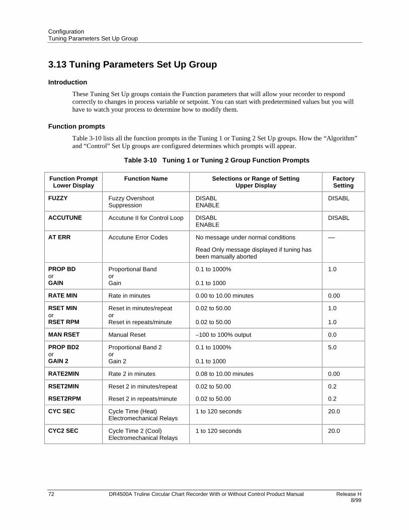
ConfigurationTuning Parameters Set Up Group
72 DR4500A Truline Circular Chart Recorder With or Without Control Product Manual Release H 8/99
3.13 Tuning Parameters Set Up Group
Introduction
These Tuning Set Up groups contain the Function parameters that will allow your recorder to respondcorrectly to changes in process variable or setpoint. You can start with predetermined values but you willhave to watch your process to determine how to modify them.
Function prompts
Table 3-10 lists all the function prompts in the Tuning 1 or Tuning 2 Set Up groups. How the “Algorithm”and “Control” Set Up groups are configured determines which prompts will appear.
Table 3-10 Tuning 1 or Tuning 2 Group Function Prompts
Function PromptLower Display
Function Name Selections or Range of SettingUpper Display
FactorySetting
FUZZY Fuzzy OvershootSuppression
DISABLENABLE
DISABL
ACCUTUNE Accutune II for Control Loop DISABLENABLE
DISABL
AT ERR Accutune Error Codes No message under normal conditions
Read Only message displayed if tuning hasbeen manually aborted
––
PROP BDorGAIN
Proportional BandorGain
0.1 to 1000%
0.1 to 1000
1.0
RATE MIN Rate in minutes 0.00 to 10.00 minutes 0.00
RSET MINorRSET RPM
Reset in minutes/repeatorReset in repeats/minute
0.02 to 50.00
0.02 to 50.00
1.0
1.0
MAN RSET Manual Reset –100 to 100% output 0.0
PROP BD2orGAIN 2
Proportional Band 2orGain 2
0.1 to 1000%
0.1 to 1000
5.0
RATE2MIN Rate 2 in minutes 0.08 to 10.00 minutes 0.00
RSET2MIN
RSET2RPM
Reset 2 in minutes/repeat
Reset 2 in repeats/minute
0.02 to 50.00
0.02 to 50.00
0.2
0.2
CYC SEC Cycle Time (Heat)Electromechanical Relays
1 to 120 seconds 20.0
CYC2 SEC Cycle Time 2 (Cool)Electromechanical Relays
1 to 120 seconds 20.0

ConfigurationSP Ramp Set Up Groups
Release H DR4500A Truline Circular Chart Recorder With or Without Control Product Manual 738/99
3.14 SP Ramp Set Up GroupsThe Setpoint Ramp 1 or 2 Set Up groups let you configure 2 setpoint ramps. Each group (SP RAMP1 andSP RAMP 2) can be configured one of three ways: ramp, rate, or setpoint program.
Setpoint Ramp
Setpoint will ramp between the current local setpoint and a final setpoint over a time interval (SP RAMP).
Setpoint Rate
The Setpoint Ramp Set Up group also contains the function parameters that let you configure a specificramp rate up and ramp rate down (SP RATE). These rates are used when the local setpoint is manuallychanged.
Setpoint Program
Also included under this group are prompts for configuring a Setpoint program (SP PROG). The promptsand instructions for Setpoint programming are presented in the Section 6 - Setpoint Ramp/SoakProgramming Option.
Function prompts
Table 3-11 lists all the function prompts in the SP RAMP 1 or SP RAMP 2 Set Up group. Configure eachramp separately. When you enable the ramp type (SP RAMP, SP RATE, SP PROG) the other two typesare hidden from the display.
Table 3-11 SP Ramp 1 or 2 Group Function Prompts
Function PromptLower Display
Function Name Selections or Range of SettingUpper Display
FactorySetting
SP RAMP* Single Setpoint RampSelection
DISABLENABLE
DISABL
TIME MIN Single Setpoint Ramp Time 0 to 255 minutes 0
FINAL SP Single Setpoint Ramp FinalSetpoint
Enter a value within the setpoint limits 100.0
SP RATE* Setpoint Rate DISABLENABLE
DISABL
EU/HR UP Rate up value (SP Rateenabled)
0 to 9999in units per hour
0
EU/HR DN Rate down value (SP Rateenabled)
0 to 9999in units per hour
0
SP PROG* Setpoint Programming(Refer to Section 6)
DISABLENABLE
DISABL
*Only one of these can be enabled at a time.

ConfigurationTimer Set Up Group
74 DR4500A Truline Circular Chart Recorder With or Without Control Product Manual Release H 8/99
3.15 Timer Set Up Group
Introduction
The Timer gives a countdown or elapsed time, after which Relay 1 energizes. If Timer is enabled, it hasexclusive control over Relay 1; Alarm 1 will not control the relay.
Function prompts
Table 3-12 lists all the function prompts in the TIMER Set Up group.
Table 3-12 Timer Group Function Prompts
Function PromptLower Display
Function Name Selections or Range of SettingUpper Display
FactorySetting
TIMER Timer Enable/Disable ENABLEDISABL
DISABL
PERIOD Timeout Period 0:00 to 99:59 0
START Start Initiation RHKEYALARM2
RHKEY
LDISPLAY Timer Display TREMET
TREM
RESET Timer Reset Control RHKEYALARM1
RHKEY
INCRMENT Timer Count Increment MINUTESECOND
MINUTE

ConfigurationAlarms Set Up Group
Release H DR4500A Truline Circular Chart Recorder With or Without Control Product Manual 758/99
3.16 Alarms Set Up Group
Introduction
This data deals with the Alarms function that is available with your recorder.
• There are six alarms available. Each alarm has two setpoints.
• You can configure each of these two setpoints to alarm on various recorder parameters. There are twoalarm output selections, high or low.
• You can also configure the two setpoints to alarm on the same event and to alarm both high and low, ifdesired. An adjustable hysteresis of 0.0% to 100.0% is configurable for each alarm.
Priority of functions that operate relays
During alarm conditions an alarm will deenergize its associated relay unless a higher priority function hasbeen configured for that relay. See Table 3-13. If you want the alarm to control the relay, do not configurea higher priority function.
Table 3-13 Priority of functions that operate relays
Relay Relay is controlled by (in order of priority)
1 1. Timer function
2. Alarm 1
2 Alarm 2 only
3 1. Controller 1 output algorithms Relay Simplex,Position Proportional, Relay Duplex,Current/Relay Duplex
2. Alarm 3
4 1. Controller 1 output algorithms PositionProportional, Relay Duplex, Current/RelayDuplex
2. Alarm 4
5 1. Controller 2 output algorithms Relay Simplex,Position Proportional, Relay Duplex,Current/Relay Duplex
2. Alarm 5
6 1. Controller 2 output algorithms PositionProportional, Relay Duplex, Current/RelayDuplex
2. Alarm 6

ConfigurationAlarms Set Up Group
76 DR4500A Truline Circular Chart Recorder With or Without Control Product Manual Release H 8/99
Function prompts
Table 3-14 lists all the function prompts in the Alarms Set Up group.
Table 3-14 Alarms Group Function Prompts
Function PromptLower Display
Function Name Selections or Range of SettingUpper Display
FactorySetting
AxS1 VAL Alarm 1, Setpoint 1 Value Value in engineering units 90
AxS2 VAL Alarm 1, Setpoint 2 Value Value in engineering units 95
AxS1TYPE Alarm 1, Setpoint 1 Type NONEIN 1 (Input 1)IN 2 (Input 2)IN 3 (Input 3)IN 4 (Input 4)RH (Relative Humidity)PV (Process Variable Loop 1)DEV (Loop 1 Deviation)OUT (Loop 1 Output)DEV2 (Loop 2 Deviation)OUT2 (Loop 2 Output)EVENT (SP Programming-Segment Event)TOTAL 1 (Totalizer to Alarm On)TOTAL 2 (Totalizer to Alarm On)TOTAL 3 (Model DR45AW only)TOTAL 4 (Model DR45AW only)
IN 1
AxS2TYPE Alarm 1, Setpoint 2 Type Same as A1S1TYPE IN 1
AxS1 H L Alarm 1, Setpoint 1 State LO (Low Alarm)H I (High Alarm)
LO
AxS1 EV SP Programming EventAlarm State for Alarm 1,Setpoint 1
BEGINEND
AxS1SCAL Alarm 1, Setpoint 1 ScalingMultiplier for TotalizerSelection
1 1000010 100000100 1E61000
1
AxS2 H L Alarm 1, Setpoint 2 State LOH I
HI
AxS2 EV SP Programming EventAlarm State for Alarm 1,Setpoint 2
BEGINEND
AxS2SCAL Alarm 1, Setpoint 2 ScalingMultiplier for TotalizerSelection
1101001000100001000001E6
1
ALx HYST Alarm Hysteresis 0.0 to 100.0 % of Input Span as appropriate 0.1
Repeat this procedure for ALARM 2, ALARM 3, ALARM 4, ALARM 5, ALARM 6.

ConfigurationAuxiliary Output Set Up Group
Release H DR4500A Truline Circular Chart Recorder With or Without Control Product Manual 778/99
3.17 Auxiliary Output Set Up Group
Introduction
The auxiliary output will supply a 4-20mA output scaled to one of four operating parameters: Input,Output, Setpoint, or Deviation. This current is supplied from a separate option card. AUX OUT 2 andAUX OUT 3 use CONTROL CURRENT OUT 1 and CONTROL CURRENT OUT 2 if CONTROL OUTALG is not set to CURRENT.
Function prompts
Table 3-15 lists all the function prompts in the Auxiliary Output Set Up group.
Table 3-15 Auxiliary Output Group Function Prompts
Function PromptLower Display
Function Name Selections or Range of SettingUpper Display
FactorySetting
AUX OUT 1 Auxiliary OutputRepresentation
DISABL PV 2IN 1 DEV 2IN 2 OUT 2PV 1 SP 2DEV 1 IN 3OUT 1 IN 4SP 1
DISABL
4 mA VAL Low Scaling Factor Low scale value to represent 4 mA 0.0
20mA VAL High Scaling Factor High scale value to represent 20 mA 100.0
Repeat this procedure for AUX OUT 2 and AUX OUT 3.

ConfigurationModbus Communications Set Up Group
78 DR4500A Truline Circular Chart Recorder With or Without Control Product Manual Release H 8/99
3.18 Modbus Communications Set Up Group
Introduction
This data deals with the Communications option that is available with your recorder. This option allows therecorder to be connected to a host computer via the Modbus protocol.
If your recorder does not have this option the prompts will not appear.
ATTENTION
Refer to Documents 51-52-25-66 and 51-52-25-69 for a complete description of the RS485Modbus Communications Option.
Function prompts
Table 3-16 lists all the function prompts in the Modbus Communications Set Up group.
Table 3-16 Modbus Communications Group Function Prompts
Function PromptLower Display
Function Name Selections or Range of SettingUpper Display
FactorySetting
ComSTATE Modbus Communications DISABLMODBUS
DISABL
Com ADDR Communications StationAddress
1 to 99 1
BAUD Communications Baud Rate 30060012002400480096001920038400
9600
XMT DLAY Transmit Delay(in milliseconds)
NONE10MSEC20MSEC30MSEC40MSEC50MSEC
NONE

ConfigurationOptions Set Up Group
Release H DR4500A Truline Circular Chart Recorder With or Without Control Product Manual 798/99
3.19 Options Set Up Group
Introduction
This data deals with various options that are available with your recorder. If your recorder does not haveany of these options the prompts will not appear.
Function prompts
Table 3-17 lists all the function prompts in the Option Set Up group.
Table 3-17 Options Group Function Prompts
Function PromptLower Display
Function Name Selections or Range of SettingUpper Display
FactorySetting
REJ FREQ Rejection Frequency 50HZ60HZ
60HZ
HF REJ High Frequency Rejection ENABLEDISABL
ENABLE
RELHUMID Relative Humidity NOYES
NO
ATMPRES Atmospheric PressureCompensation
590 to 800 mmHg ––
DEVIATION Deviation Recording Action NONESETPNTCHAN1
NONE
DEVSETPT Deviation Setpoint Value –999.0 to 9999 0
SCROLL Lower Display Scroll NONE1 SEC2 SEC3 SEC
NONE
GRANDTOT Grand Totalizer ENABLEDISABL
DISABL

ConfigurationEvent Message Configuration
80 DR4500A Truline Circular Chart Recorder With or Without Control Product Manual Release H 8/99
3.20 Event Message Configuration
Introduction
This Set Up group allows you to specify an event message to be printed on a designated area of the chartwhen triggered by a specific selectable actuation.
Function prompts
Table 3-18 lists all the function prompts in the “Event Message” Set Up group.
Table 3-18 Event Message Group Function Prompts
Function PromptLower Display
Function Name Selections or Range of SettingUpper Display
FactorySetting
EVENT1 Event 1 Trigger NONEEXTSW1EXTSW2ALARM1ALARM2ALARM3ALARM4ALARM5ALARM6
NONE
MESSAGE1 Message for Event 1(up to six characters)
0 to 9A to Z+–/(blank)*
EVENT1
POSITON1 Chart Position for Message1 Printing
0 to 100% 87.3
EVENT 2 Event 2 Trigger NONEEXTSW1EXTSW2ALARM1ALARM2ALARM3ALARM4ALARM5ALARM6
NONE
MESSAGE2 Message for Event 2(up to six characters)
0 to 9A to Z+–/(blank)*
EVENT2
POSITON2 Chart Position for Message2 Printing
0 to 100% 85.5

ConfigurationEvent Message Configuration
Release H DR4500A Truline Circular Chart Recorder With or Without Control Product Manual 818/99
Function PromptLower Display
Function Name Selections or Range of SettingUpper Display
FactorySetting
EVENT 3 Event 3 Trigger NONEEXTSW1EXTSW2ALARM1ALARM2ALARM3ALARM4ALARM5ALARM6
NONE
MESSAGE3 Message for Event 3(up to six characters)
0 to 9A to Z+–/(blank)*
EVENT3
POSITON3 Chart Position for Message3 Printing
0 to 100% 83.6
EVENT 4 Event 4 Trigger NONEEXTSW1EXTSW2ALARM1ALARM2ALARM3ALARM4ALARM5ALARM6
NONE
MESSAGE4 Message for Event 4(up to six characters)
0 to 9A to Z+–/(blank)*
EVENT4
POSITON4 Chart Position for Message4 Printing
0 to 100% 80.0
EVENT 5 Event 5 Trigger NONEEXTSW1EXTSW2ALARM1ALARM2ALARM3ALARM4ALARM5ALARM6
NONE
MESSAGE5 Message for Event 5(up to six characters)
0 to 9A to Z+–/(blank)*
EVENT5
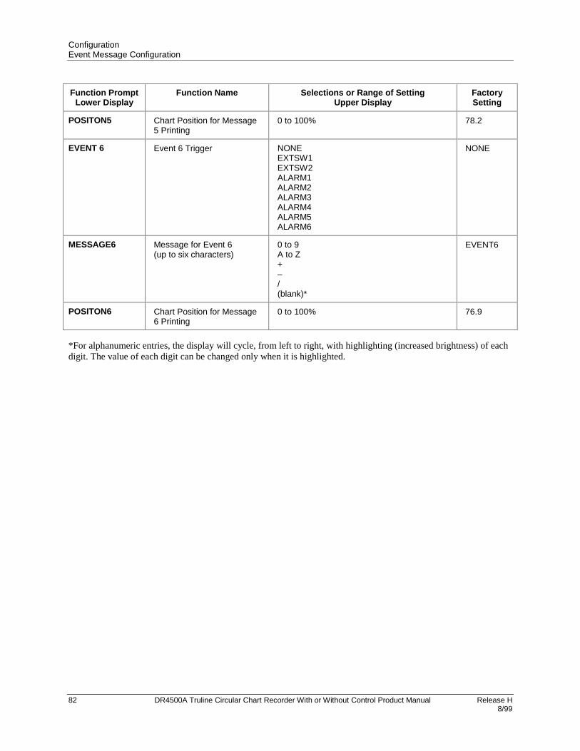
ConfigurationEvent Message Configuration
82 DR4500A Truline Circular Chart Recorder With or Without Control Product Manual Release H 8/99
Function PromptLower Display
Function Name Selections or Range of SettingUpper Display
FactorySetting
POSITON5 Chart Position for Message5 Printing
0 to 100% 78.2
EVENT 6 Event 6 Trigger NONEEXTSW1EXTSW2ALARM1ALARM2ALARM3ALARM4ALARM5ALARM6
NONE
MESSAGE6 Message for Event 6(up to six characters)
0 to 9A to Z+–/(blank)*
EVENT6
POSITON6 Chart Position for Message6 Printing
0 to 100% 76.9
*For alphanumeric entries, the display will cycle, from left to right, with highlighting (increased brightness) of eachdigit. The value of each digit can be changed only when it is highlighted.

ConfigurationLockout Set Up Group
Release H DR4500A Truline Circular Chart Recorder With or Without Control Product Manual 838/99
3.21 Lockout Set Up Group
Introduction
These are the parameters that you will select to lockout any unauthorized changes to the recorder’sconfiguration and calibration prompts. You must know the password in order to change the Lockoutconfiguration.
Function prompt
Table 3-19 lists all the function prompts in the Lockout Set Up group.
Table 3-19 Lockout Group Function Prompts
Function PromptLower Display
Function Name Selections or Range of SettingUpper Display
FactorySetting
PASSWORD Lockout Password Select up to 4 alphanumeric characters(++++ is factory default password)
For more information on password security,refer to Appendix C.
XXXX
LOCKOUT Lockout NONECALIB+CONFMAX
CALIB
CHANGE Change Password 0 to 9A to Z
XXXX
ATTENTION
Configuration can also be locked using S1 switch on the main printed circuit board. Refer toSubsection 2.9 – Configuration Lockout Switch.
This feature also includes the special screw and plate that provide for the lead seal capability for sealing thechart plate.

ConfigurationAdjust Printing
84 DR4500A Truline Circular Chart Recorder With or Without Control Product Manual Release H 8/99
3.22 Adjust Printing
Introduction
This data deals with the “Adjust Printing” feature of the Truline recorder. This feature is important to theoperation of the hot stylus pen.
Configuration choices are provided for PEN TYPE and the selection must match the stylus design.
• PEN TYPE = NORMAL is for the high-speed stylus design.
• PEN TYPE = JEWEL is used only for abrasion resistant stylus design.
CAUTION
If the “JEWEL” selection is accidentally used with the high-speed design, the life of that styluswill be shortened.
You can also make slight adjustments to the print contrast.
Function prompt
Table 3-20 lists all the function prompts in the Adjust Set Up group.
Table 3-20 Adjust Group Function Prompts
Function PromptLower Display
Function Name Selections or Range of SettingUpper Display
FactorySetting
TRACE LN Trace Line Contrast DARKMEDIUMLIGHT
MEDIUM
GRID LN Grid Line Contrast DARKMEDIUMLIGHT
MEDIUM
PEN TYPE Stylus Selection NORMAL – Select if high speed stylus (blacktip) is installed.
JEWEL – Select if abrasion resistant stylus(beige tip) is installed.
NORMAL

ConfigurationConfiguration Record Sheet
Release H DR4500A Truline Circular Chart Recorder With or Without Control Product Manual 858/99
3.23 Configuration Record Sheet
Keep a record
Enter the value or selection for each prompt on this sheet so you will have a record of how your recorderwas configured.
GroupPrompt
Functionprompt
Value orSelection
FactorySetting
GroupPrompt
Functionprompt
Value orSelection
FactorySetting
INPUT 1
INPUT 2
INPUT 3
INPUT 4
DECIMALUNITSENGUNITSIN1 TYPEXMITTERIN1 HIIN1 LOCUTOFF 1INPTCOMPFILTER 1BURNOUTEMISSIV
DECIMALUNITSENGUNITSIN2 TYPEXMITTERIN2 HIIN2 LOCUTOFF 2INPTCOMPFILTER 2BURNOUTEMISSIV
DECIMALUNITSENGUNITSIN3 TYPEXMITTERIN3 HIIN3 LOCUTOFF 3INPTCOMPFILTER 3BURNOUTEMISSIV
DECIMALUNITSENGUNITSIN4 TYPEXMITTERIN4 HIIN4 LOCUTOFF 4INPTCOMPFILTER 4BURNOUTEMISSIV
____________________________________________________________________________________
____________________________________________________________________________________
____________________________________________________________________________________
____________________________________________________________________________________
XXX.XDEGF—100PTLINEAR900-300000UP.01
XXX.XDEGF—100PTLINEAR900-300000UP.01
XXX.XDEGF—100PTLINEAR900-300000UP.01
XXX.XDEGF—100PTLINEAR900-300000DEGF.01
PEN 1
PEN 2
PEN 3
PEN 4
CHART
PEN1INCHART1HICHART1LOPEN1ONPEN1OFFMAJORDIVMINORDIVRNG1TAG
PEN2INCHART2HICHART2LOPEN2ONPEN2OFFMAJORDIVMINORDIVRNG2TAG
PEN3INCHART3HICHART3LOPEN3ONPEN3OFFMAJORDIVMINORDIVRNG3TAG
PEN4INCHART4HICHART4LOPEN4ONPEN4OFFMAJORDIVMINORDIVRNG4TAG
CHRTSPDHOUR/REVTIME DIVMINORDIVCONTINUECHARTNAMHEADERREM CHRTWAKE MINWAKE HRWAKE DAYWAKE MON
________________________________________________________
________________________________________________________
________________________________________________________
________________________________________________________
____________________________________________________________________________________
INPUT1302.0292.091.093.01010RNG1
INPUT2302.0292.091.093.01010RNG2
INPUT3302.0292.091.093.01010RNG3
NPUT4302.0292.091.093.01010RNG4
XHR1224FourNOTRULINNONONE0000

ConfigurationConfiguration Record Sheet
86 DR4500A Truline Circular Chart Recorder With or Without Control Product Manual Release H 8/99
GroupPrompt
Functionprompt
Value orSelection
FactorySetting
GroupPrompt
Functionprompt
Value orSelection
FactorySetting
TIME
TOTAL 1
TOTAL 2
INP ALG
CONTROL 1
MINUTESHOURSDAYMONTHYEARDAY
(Value)RSET TOTTOTAL 1TOTAL EURATESCALERRSETABLE
(Value)RSET TOTTOTAL 2TOTAL EURATESCALERRSETABLE
INP ALGCOEFFPV HIGHPV LOWRATIO ABIAS ARATIO BBIAS BRATIO CBIAS CPOLYNOMC0 VALUEC1 VALUEC2x10-1C3x10-3C4x10-5C5x10-7
CONTROL1PID SETSSW VALUESP SOURCRATIOBIASSP TRACKPOWER UPPWR OUTSPHILIMSPLOLIMACTIONOUT HILIMOUT LOLIMDROPOFFDEADBANDOUT HYSTFAILSAFEREM SWMAN KEYPBorGAINMINorRPMCONT1ALGOUT1ALG4-20 RNG
__________________________________________
_________________________________________________
_________________________________________________
_______________________________________________________________________________________________________________________
_______________________________________________________________________________________________________________________________________________________________________________
Settolocaltime
E0 GALNODISABLGALSECOND1NO
E0 GALNODISABLGALSECOND1NO
NONE1.00.00.01.00.01.00.01.00.0NONE000000
ENABLE1ONLY0.01LOCAL1.00NONEMANUALLAST5000REVRSE100.000.02.00.550NONEENABLEGAINMINPIDACURRENT50PCT
CONTROL 2
TUNING 1
CONTROL2PID SETSSW VALUESP SOURCRATIOBIASSP TRACKPOWER UPPWR OUTSP HILIMSP LOLIMACTIONOUTHILIMOUTLOLIMDROPOFFDEADBANDOUT HYSTFAILSAFEREM SW2MAN KEYPBorGAINMINorRPMCONT2ALGOUT2ALG4-20 RNG
FUZZYACCUTUNEAT ERRPROP BDorGAINRATE MINRSET MINorRSET RPMMAN RSETCYCSECPROP BD2orGAIN 2RATE2MINRSET2MINorRSET2RPMCYC2SEC
_______________________________________________________________________________________________________________________________________________________________________________
______________Read only_______
_____________________
____________________________
_____________________
______________
ENABLE1ONLY0.01LOCAL1.00NONEMANUAL500LAST0REVRSE100.000.02.00.550NONEENABLEGAINMINPIDACURRENT50PCT
DISABLDISABL
1.0
1.00.001.0
1.00.020.01.0
1.00.001.0
1.020.0

ConfigurationConfiguration Record Sheet
Release H DR4500A Truline Circular Chart Recorder With or Without Control Product Manual 878/99
GroupPrompt
Functionprompt
Value orSelection
FactorySetting
GroupPrompt
Functionprompt
Value orSelection
FactorySetting
TUNING 2
SP RAMP1
SP RAMP2
SPP SEGS
SPP EVNT
TIMER
FUZZYACCUTUNEAT ERRPROP BDorGAINRATE MINRSET MINorRSET RPMMAN RSETCYCSECPROP BD2orGAIN 2RATE2MINRSET2MINorRSET2RPMCYC2SEC
SP RAMPTIME MINFINAL SPSP RATEEU/HR UPEU/HR DNSP PROGRECYCLESSOAK DEVPROFILESTATERECOVERYPROG END
SP RAMPTIME MINFINAL SPSP RATEEU/HR UPEU/HR DNSP PROGRECYCLESSOAK DEVPROFILESTATERECOVERYPROG END
PRx STRTPRx ENDRAMPUNITSYNC 1+2SEGxRAMPSEGx SPSEGxTIME
SEGx EV
TIMERPERIODSTARTLDISPLAYRSETINCRMENT
______________Read only_______
_____________________
____________________________
_____________________
______________
___________________________________________________________________________________________
___________________________________________________________________________________________
_________________________________________________
_______
__________________________________________
DISABLDISABL—1.0
1.00.001.0
1.00.020.01.0
1.00.001.0
1.020.0
DISABL0100.0DISABL——DISABL——————
DISABL0100.0———DISABL——————
———————
—
DISABL0:01KEYTREMKEYMIN
ALARM 1
ALARM 2
ALARM 3
ALARM 4
ALARM 5
A1S1 VALA1S2 VALA1S1TYPEA1S2TYPEA1S1 H LA1S1 EVA1S1SCALA1S2 H LA1S2 EVA1S2SCALAL1 HYST
A2S1 VALA2S2 VALA2S1TYPEA2S2TYPEA2S1 H LA2S1 EVA2S1SCALA2S2 H LA2S2 EVA2S2SCALAL2 HYST
A3S1 VALA3S2 VALA3S1TYPEA3S2TYPEA3S1 H LA3S1 EVA3S1SCALA3S2 H LA3S2 EVA3S2SCALAL3 HYST
A4S1 VALA4S2 VALA4S1TYPEA4S2TYPEA4S1 H LA4S1 EVA4S1SCALA4S2 H LA4S2 EVA4S2SCALAL4 HYST
A5S1 VALA5S2 VALA5S1TYPEA5S2TYPEA5S1 H LA5S1 EVA5S1SCALA5S2 H LA5S2 EVA5S2SCALAL5 HYST
_____________________________________________________________________________
_____________________________________________________________________________
_____________________________________________________________________________
_____________________________________________________________________________
_____________________________________________________________________________
9095INPUT1INPUT1LO—1HI—10.1
9095INPUT1INPUT1LO—1HI—10.1
9095INPUT1INPUT1LO—1HI—10.1
9095INPUT1INPUT1LO—1HI—10.1
9095INPUT1INPUT1LO—1HI—10.1

ConfigurationConfiguration Record Sheet
88 DR4500A Truline Circular Chart Recorder With or Without Control Product Manual Release H 8/99
GroupPrompt
Functionprompt
Value orSelection
FactorySetting
GroupPrompt
Functionprompt
Value orSelection
FactorySetting
ALARM 6
AUX OUT1
AUX OUT2
AUX OUT3
COMM
OPTIONS
EVNT MSG
LOCKOUT
ADJUST
A6S1 VALA6S2 VALA6S1TYPEA6S2TYPEA6S1 H LA6S1 EVA6S1SCALA6S2 H LA6S2 EVA6S2SCALAL6 HYST
AUX OUT14 mA VAL20mA VAL
AUX OUT24 mA VAL20mA VAL
AUX OUT34 mA VAL20mA VAL
ComSTATECom ADDRBAUDXMT DLAY
REJ FREQHF REJRELHUMIDATMPRESDEVIATIONDEVSETPTSCROLLGRANDTOT
EVENT 1MESSAGE1POSITION1EVENT 2MESSAGE2POSITION2EVENT 3MESSAGE3POSITION3EVENT 4MESSAGE4POSITION4EVENT 5MESSAGE5POSITION5EVENT 6MESSAGE6POSITION6
PASSWORDLOCKOUTCHANGE
TRACE LNGRID LNPEN TYPE
_____________________________________________________________________________
_____________________
_____________________
_____________________
____________________________
________________________________________________________
______________________________________________________________________________________________________________________________
_____________________
_____________________
9095INPUT1INPUT1LO—1HI—10.1
DISABL0.0100.0
DISABL0.0100.0
DISABL0.0100.0
DISABL19600NONE
60 ENABLENO—NONE0NONEDISABL
NONEEVENT187.3NONEEVENT285.5NONEEVENT383.6NONEEVENT480.0NONEEVENT578.2NONEEVENT676.9
XXXXCALIBXXXX
MEDIUMMEDIUMNORMAL

Release H DR4500A Truline Circular Chart Recorder With or Without Control Product Manual 898/99
4. Configuration Parameter Definitions
4.1 Overview
Introduction
This section provides information for all the user-configurable control parameters listed in theconfiguration section. If you aren’t familiar with these parameters, this section gives you the parameterprompt, the selection or range of setting that you can make, and a definition of how each parameter settingaffects recorder performance. It will also refer you to any other prompts that might be affected by yourselection.
Parameter groups and prompts
• The control information is found in three configuration groups which are accessed by the SET UP key.
• Each of these groups contains prompts, viewed in the lower display, which deal with functions that arepertinent to that particular group. These are accessed by pressing the FUNC key.
• The selections or values are listed in the upper display. Refer to Section 3 - Configuration for step bystep instructions.
What’s in this section?
The table below lists the topics that are covered in this section. They are listed in the order of theirappearance in the recorder.
Topic See Page
4.1 Overview 89
4.2 Input Parameters Set Up Group 90
4.3 Pen Parameters Set Up Group 94
4.4 Chart Parameters Set Up Group 96
4.5 Time Parameters Set Up Group 99
4.6 Total Parameters Set Up Group 100
4.7 Input Algorithm Set Up Group 102
4.8 Control Parameters Set Up Group 105
4.9 Tuning Parameters Set Up Group 115
4.10 Setpoint Ramp Set Up Group 118
4.11 Timer Set Up Group 120
4.12 Alarms Set Up Group 121
4.13 Auxiliary Output Set Up Group 124
4.14 Modbus Communications Set Up Group 126
4.15 Options Set Up Group 127
4.16 Event Message Set Up Group 129
4.17 Lockout Parameters Set Up Group 130
4.18 Printing Characteristics Adjustments 131

Configuration Parameter DefinitionsInput Parameters Set Up Group
90 DR4500A Truline Circular Chart Recorder With or Without Control Product Manual Release H 8/99
4.2 Input Parameters Set Up Group
Introduction
These are the parameters required for input 1, 2, 3, or 4; temperature units, decimal location, actuation,transmitter characterization, high and low range values in engineering units, input compensation, filter, andburnout.
Input group prompts
Table 4-1 lists all the function prompts in the Input 1, 2, 3, or 4 setup group and their definitions.
Table 4-1 Input Group Definitions
Lower DisplayPrompt
Upper DisplayRange of Setting or Selection
Parameter Definition
DECIMAL
XXXXXXX.XXX.XXX.XXX
DECIMAL POINT LOCATION -- This selectiondetermines where the decimal point appears in thedisplay.
NoneOne PlaceTwo PlacesThree Places
NOTE: Auto-ranging will occur when one decimalposition has been selected and the value increasesabove 999.9 but auto-ranging will not similarly occurwhen two decimal positions are selected.
UNITS
DEG FDEG CEU
TEMPERATURE UNITS -- This selection will beindicated on the PV display.
If you select EU, go to prompt “ENGUNITS”
Degrees FahrenheitDegrees CelsiusEngineering Units
ENGUNITS
0 to 9A to Z+–/(blank)
ENGINEERING UNITS – Make up 5 selections to createunit identifier.
• For example, create unit identifier H2O by selectingan “H” from A to Z, a “2” from 0 to 9, and an “O” fromA to Z.
• For alphanumeric entries, the display will cycle, fromleft to right, with highlighting (increased brightness) ofeach digit. The value of each digit can be changedonly when it is highlighted.

Configuration Parameter DefinitionsInput Parameters Set Up Group
Release H DR4500A Truline Circular Chart Recorder With or Without Control Product Manual 918/99
Lower DisplayPrompt
Upper DisplayRange of Setting or Selection
Parameter Definition
INn TYPE
(n = 1, 2, 3, or 4)
B TCE TC HE TC LJ TC HJ TC LK TC HK TC LNNM TC1
NIC TC1
R TC1
S TCT TC HT TC LW TC H1
W TC L1
100 PT200 HI2200 LO2
500 PT100 RH4-20mA0-10mV10-50m0-5 V0-10 VRADIAM
INPUT ACTUATION TYPE -- This selection determineswhat actuation you are going to use for input one. Besure that the values configured for high and low chartrange, soak setpoint, alarm setpoint, etc. are within themeasuring range for the selected actuation type.
B thermocouple 105 to 3300°F 41 to 1815°CE thermocouple high –454 to 1832°F –270 to 1000°CE thermocouple low –200 to 1100°F –129 to 593°CJ thermocouple high 0 to 1600°F –18 to 871°CJ thermocouple low 20 to 770°F –7 to 410°CK thermocouple high –320 to 2500°F –196 to 1371°CK thermocouple low –20 to 1000°F –29 to 538°CNNM NiNiMo thermocouple 32 to 2500°F 0 to 1371°CNIC Nicrosil-Nisil thermocouple 0 to 2372°F –178 to 1300°CR thermocouple 0 to 3100°F –18 to 1704°CS thermocouple 0 to 3100°F –18 to 1704°CT thermocouple high –300 to 700°F –184 to 371°CT thermocouple low –200 to 500°F –129 to 316°CW5W26 thermocouple high 0 to 4200°F –18 to 2316°CW5W26 thermocouple low 0 to 2240°F –18 to 1227°C100 Ohm–RTD –300 to 1200°F –184 to 649°C200 Ohm–RTD 32 to 752 0 to 400200 Ohm–RTD 32 to 392 0 to 200500 Ohm–RTD –300 to 900°F –184 to 482°C100 Ohm–RTD –130 to 392°F –90 to 200°C4 to 20 Milliamps3
0 to 10 Millivolts3
10 to 50 Millivolts3
0 to 5 Volts3
0 to 10 Volts3
Radiamatic 1400 to 3400°F 760 to 1871°C
1Only available with Model DR45AT2Only available with Model DR45AR3Go to prompt “XMITTER” to characterize the input.

Configuration Parameter DefinitionsInput Parameters Set Up Group
92 DR4500A Truline Circular Chart Recorder With or Without Control Product Manual Release H 8/99
Lower DisplayPrompt
Upper DisplayRange of Setting or Selection
Parameter Definition
XMITTER
B TCE TC HE TC LJ TC HJ TC LK TC HK TC LNNM HNIC TCR TCS TCT TC HT TC LW TC HW TC L100 PT500 PT100 RHLINEARSQROOT
TRANSMITTER CHARACTERIZATION — Thisselection lets you instruct the recorder to characterize alinear input to represent a nonlinear one.
• NOTE: Prompt only appears when a linear actuationis selected at prompt ‘IN1 TYPE”.
• FOR EXAMPLE: If input 1 is a 4 to 20 mA signal, butthe signal represents a type "K" thermocouple; select"K TC H" and the recorder will characterize the 4 to20 mA signal so that it is treated as a type "K"thermocouple input (high range).
B Type ThermocoupleE Type Thermocouple HighE Type Thermocouple LowJ Type Thermocouple HighJ Type Thermocouple LowK Type Thermocouple HighK Type Thermocouple LowNNM NiNiMo Type Thermocouple HighNIC Nicrosil Nisil ThermocoupleR Type ThermocoupleS Type ThermocoupleT Type Thermocouple HighT Type Thermocouple LowW5W26 Type Thermocouple HighW5W26 Type Thermocouple Low100 Ohm–RTD500 Ohm–RTD100 Ohm –RTDLinear RangeExtracts Square Root
INn HI
(n = 1, 2, 3, or 4)
–999.9 to 9999.
or
–999 to 9999in engineering units
INPUT HIGH RANGE VALUE in engineering units isdisplayed for all inputs but can only be configured forlinear or square root transmitter characterization.Otherwise, this is a read-only display of the higher rangevalue for the selected T/C or RTD input includingtransmitter characterization, if applicable.
• Scale the #1 input signal to the display value youwant for 100%.
• EXAMPLE:Actuation (Input) = 4 to 20 mAProcess Variable = FlowRange of Flow = 0 to 250 Gal/MinHigh Range display value = 250Then 20 mA = 250 Gal/Min
The control setpoint will be limited by the range of unitsselected here.

Configuration Parameter DefinitionsInput Parameters Set Up Group
Release H DR4500A Truline Circular Chart Recorder With or Without Control Product Manual 938/99
Lower DisplayPrompt
Upper DisplayRange of Setting or Selection
Parameter Definition
INn LO
(n = 1, 2, 3, or 4)
–999.9 to 9999.
or
–999 to 9999in Engineering units
INPUT LOW RANGE VALUE in engineering units isdisplayed for all inputs but can only be configured forlinear or square root transmitter characterization.
• Otherwise, this is a read-only display of the low rangevalue for the selected T/C or RTD input includingtransmitter characterization, if applicable.
• Scale the input signal to the display value you wantfor 0%. See example on previous page. The controlsetpoint for Input will be limited by the range of unitsselected here.
CUTOFF n
(n = 1, 2, 3, or 4)
0 to 100% of Input Range LOW FLOW CUTOFF—Lets you set a value in percentof range below which the applicable totalizer does notincrement.
ATTENTION Prompt appears only if totalizer optionis present in the recorder.
INPTCOMP –999.9 to 9999. INPUT COMPENSATION — used to compensate theinput for drift of an input value due to deterioration of asensor, or some other cause; select the value you wanton the input.
FILTER n
(n = 1, 2, 3, or 4)
0 to 120 secondsNo filter = 0
FILTER FOR INPUT — a software digital filter isprovided for the input to smooth the input signal. Youcan configure the first order lag time constant from 1 to120 seconds. If you do not want filtering, enter 0.
BURNOUT
NONE
UP
DOWN
BURNOUT PROTECTION (SENSOR BREAK) providesmost input types with upscale or downscale protection ifthe input fails.
• Not available for inputs 0-5V, 0-10V, or 4-20 mA.
NO BURNOUT — Failsafe output applied for failedinput.
UPSCALE BURNOUT will make the indicated PV signalincrease when a sensor fails, and flash the upperdisplay.
DOWNSCALE BURNOUT will make the indicated PVsignal decrease when a sensor fails, and flash the upperdisplay.
NOTE: For no Burnout, (that is, “None,”) to functionproperly on a linear input, there must be a droppingresistor directly across the input terminals (that is, notremote), then the unit can detect the “zero” voltage thatoccurs when the 4-20 mA line is opened.
EMISSIV .01 to 1.00 EMISSIVITY is a correction factor applied to theRadiamatic input signal that is the ratio of the actualenergy emitted from the target to the energy whichwould be emitted if the target were a perfect radiator.Available only for “Radiamatic” inputs.
Repeat the procedure for INPUT 2, INPUT 3, and INPUT 4 configuration.

Configuration Parameter DefinitionsPen Parameters Set Up Group
94 DR4500A Truline Circular Chart Recorder With or Without Control Product Manual Release H 8/99
4.3 Pen Parameters Set Up Group
Introduction
The functions listed in this group deal with how to configure pen #1, pen #2, pen #3, or pen #4. Theprocedure for configuring each pen is the same. The prompts shown in Table 4-2 show PEN 1.
• Press the SET UP key until PEN 1, PEN 2, PEN 3, or PEN 4 appears in the display.
Pen 1-2-3-4 group prompts
Table 4-2 lists all the function prompts in the Pen 1, 2, 3, 4 set up groups and their definitions.
Table 4-2 Pen 1, 2, 3, or 4 Group Definitions
Lower DisplayPrompt
Upper DisplayRange of Setting or Selection
Parameter Definition
PENn
(n - 1, 2, 3 or 4)
ENABLEDISABL
PEN RECORD —This selection lets you enable ordisable the pen (channel) record
• Remember, the lower display prompt could readPEN2, PEN3, or PEN4.
PENnIN
(n = 1, 2, 3 or 4) INPUT 1INPUT 2INPUT 3INPUT 4
RH
OUTPT1OUTPT2SETPT1SETPT2DGTL1
DGTL2
PV1
PEN INPUT—What do you want the pen to record?
INPUT 1—records Input 1INPUT 2—records Input 2INPUT 3—records Input 3INPUT 4—records Input 4
RELATIVE HUMIDITY—records in %RH. It initiates anexternal calculation for measuring relative humidity.INPUT 1, IN TYP must be configured for 100 PT. INPUT2, IN TYP must be configured for 100 RH. The RHprompt only appears when RELHUMID prompt in theOPTIONS group is configured as YES.OUTPUT 1—records Output 1OUTPUT 2—records Output 2SETPOINT 1—records Setpoint 1SETPOINT 2—records Setpoint 2DIGITAL 1 INPUT—records EVENT pen function oncontact closure across digital 1 input.DIGITAL 2 INPUT—records EVENT pen function oncontact closure across digital 2 input.PV1—records calculated PV1 when an input algorithm(INP ALG) has been selected in the Options group.(Available only in units with software Math Option.)
CHARTnHI
(n = 1, 2, 3 or 4)
–999.0 to 999 CHART HIGH RANGE VALUE—Enter a value thatcorresponds with the chart high range value forpen 1 (pen 2, pen 3, or pen 4).
CHARTnLO
(n = 1, 2, 3 or 4)
–999.0 to 999 CHART RANGE LOW VALUE—Enter a value thatcorresponds with the chart low range value forpen 1 (pen 2, pen 3, or pen 4).

Configuration Parameter DefinitionsPen Parameters Set Up Group
Release H DR4500A Truline Circular Chart Recorder With or Without Control Product Manual 958/99
Lower DisplayPrompt
Upper DisplayRange of Setting or Selection
Parameter Definition
PENnON
(n = 1, 2, 3 or 4)
0 to 100% PEN CHART POSITION FOR ON EVENT — This is theevent marker configuration using digital inputs.Select the chart position where pen 1 (pen 2, pen 3, andpen 4) is to mark (trace) occurrence of an ON event.
• Prompt only appears if DGTL1 or 2 is selected as pen1 (pen 2, pen 3, or pen 4) input.
PENnOFF
(n = 1, 2, 3 or 4)
0 to 100% PEN CHART POSITION FOR OFF EVENT — This isthe event marker configuration using digital inputs.Select the chart position where Pen 1 (pen 2, pen 3, andpen 4) is to mark (trace) occurrence of an OFF event.
• Prompt only appears if DGTL1 or 2 is selected aspen 1 (pen 2, pen 3, or pen 4) input.
MAJORDIV 2 to 10 MAJOR CHART DIVISIONS — This is the number ofMajor Divisions in range of chart 1 (2, 3, or 4) scale(between CHART1HI and CHART1LO). Must divideevenly into chart range.
ATTENTION The values of major divisions are nowprinted with decimal points when possible. Therestriction is four characters, including the decimal and(–) sign.
EXAMPLES:
Pen Range Print Format
0 to 99 XX.X
0 to 9 X.XX
–9 to 9 XX.X
–99 to 99 XXX
0 to 999 XXX
MINORDIV 2 to 10 MINOR CHART DIVISIONS — This is the number ofMinor Divisions in range of chart 1 (2, 3, or 4) scale(increments in each Major Division).
RNGnTAG
(n = 1, 2 , 3 or 4)
0 to 9A to Z+–/(blank)
RANGE 1 TAG NAME — Enter a tag name for chart 1(2, 3, or 4) range. It can be up to 5 characters.
• For alphanumeric entries, the display will cycle, fromleft to right, with highlighting (increased brightness) ofeach digit. The value of each digit can only bechanged when it is highlighted.
Repeat this procedure for PEN 2, PEN 3, and PEN 4 configuration.

Configuration Parameter DefinitionsChart Parameters Set Up Group
96 DR4500A Truline Circular Chart Recorder With or Without Control Product Manual Release H 8/99
4.4 Chart Parameters Set Up Group
Introduction
The functions listed in this group deal with how the chart will be set up. It includes time divisions, speed,name, rotation, header, remote activation, and wake time parameters that have to be set for the proper chartfunction.
CAUTION
Before making any configuration changes to the “Chart” Set Up group, place the recorder in“Chart Hold”. Press the CHART key to stop the chart rotation. Press again after configurationentry is made.
Chart group prompts
Table 4-3 lists all the function prompts in the chart parameters setup group and their definitions.
Table 4-3 Chart Parameters Group Definitions
Lower DisplayPrompt
Upper DisplayRange of Setting or Selection
Parameter Definition
CHRTSPD
8HR12HR24HR7DAYSXHR
CHART SPEED — This is the time it will take to drivethe chart one complete revolution.
8 Hour revolution12 Hour revolution24 Hour revolution7 Day revolutionX hour revolution - make Hours per Revolution selectionat prompt “HOUR/REV”.
ATTENTION If the chart speed selection is 8 hr/8division, 12 hr/12 division, 24 hr/24 division, 7 day/14division, or 7 day/21 division, then standard chart hasbeen selected.
This means that the chart will be printed with the timelines on the hour. Limited information will be printed onthe chart during the first incomplete segment followingchart initiation and before the first valid hour mark.
NOTE: If X hour chart is selected, standard charts aredisabled.
HOUR/REV 6 to 744 Hours(12 hrs for abrasion resistantpen)
HOURS PER REVOLUTION — Set the desired chartspeed. Appears only if XHR was selected at prompt“CHRT SPD”.
ATTENTION Below 8 hrs chart speed (24 hrs withabrasion resistant pen) printing may be degraded.

Configuration Parameter DefinitionsChart Parameters Set Up Group
Release H DR4500A Truline Circular Chart Recorder With or Without Control Product Manual 978/99
Lower DisplayPrompt
Upper DisplayRange of Setting or Selection
Parameter Definition
TIME DIVMAJOR
TIME DIVMINOR
8 to 24 time periods
Software set for 4 or 8seg/minor time divisions
TIME DIVISION — This is the number of time periodsinto which the chart record is to be divided.
TIME PERIOD
21422
ATTENTION Make sure that the chart selected isevenly divisible into the time periods. For example: 7day = 14 or 21 lines.
CONTINUE
YESNO
CONTINUE CHART ROTATION — Do you want tocontinue or stop the chart drive after a single 360°rotation.Yes—continue chart driveNo—stop chart drive (If “NO” is selected, chart papermust be replaced for proper printout.)
CHARTNAM 0 TO 9A TO Z+–/(BLANK)
CHART NAME - This is where you determine the chartname identifier. For example: TRULINE/4.
• For alphanumeric entries, the display will cycle, fromleft to right, with highlighting (increased brightness) ofeach digit.
• The value of each digit can be changed only when itis highlighted.
HEADER YESNO
HEADER FOR CHART – Is the header to be printedeach time the recorder goes from chart hold to chart runthe CHART key is pressed.
HEADER EXAMPLE
14:57________ 08/25/93
<010:020> TRULIN
Chart Ranges (Lo-Hi) Date (mo/day/yr)
Pen (channel) nos.
Chart Speed
Time Division Chart Name
Engineering Units
21423
P1 = 0 TO 350 P2 = 50 TO 450 P3 = 0 TO 1000 P4 = 450 TO 50
PSI GPM PSI GPM
Time (24 HR clock)
• If you select “NO” only the chart name will be printed.

Configuration Parameter DefinitionsChart Parameters Set Up Group
98 DR4500A Truline Circular Chart Recorder With or Without Control Product Manual Release H 8/99
Lower DisplayPrompt
Upper DisplayRange of Setting or Selection
Parameter Definition
REM CHRT
NONEEXT SW1
EXT SW2
ALARM 1ALARM 2TIMEALARM 3ALARM 4ALARM 5ALARM 6
REMOTE CHART ACTIVATION – Select the desiredfunction to activate the chart from a remote location oran internal signal.
NONE - No selectionEXT SW 1 - External Switch #1 activates chart
(DIgital Input #1)EXT SW 2 - External Switch #2 activates chart
(Digital Input #2)ALARM 1 - Alarm 1 activates chartALARM 2 - Alarm 2 activates chartTIME - Wake Time activates chartALARM 3 - Alarm 3 activates chartALARM 4 - Alarm 4 activates chartALARM 5 - Alarm 5 activates chartALARM 6 - Alarm 6 activates chart
• If you select “TIME”, set wake minutes at prompt“WAKE MIN” and wake hours at prompt “WAKE HR”.
WAKE MIN 0 to 59 WAKE MINUTES – Wake time specifies time, inminutes, at which pen record will begin. Appears only if“Time” is selected at prompt “REM CHRT.”
WAKE HR 0 to 23 WAKE HOUR – Wake time specifies time, in hours, atwhich pen record will begin. Appears only if “Time” isselected at prompt “REM CHRT.”
WAKE DAY 0 to 31 WAKE DAY – Wake time specifies time, in days, atwhich pen record will begin. Appears only if “Time” isselected at prompt “REM CHRT.”
ATTENTION If day is set to “0”, the wake up dayand month are ignored and only a successful match ofthe hours and minutes will cause the chart to wake up.
WAKE MON 1 to 12 WAKE MONTH – Wake time specifies time, in months,at which pen record will begin. Appears only if “Time” isselected at prompt “REM CHRT.”

Configuration Parameter DefinitionsTime Parameters Set Up Group
Release H DR4500A Truline Circular Chart Recorder With or Without Control Product Manual 998/99
4.5 Time Parameters Set Up Group
Introduction
The functions listed in this group deal with how to configure the real-time in minutes, hours, days, months,and years. There is also a selection for days of the week.
Time group prompts
Table 4-4 lists all the function prompts in the Time parameters setup group and their definitions.
Table 4-4 Time Parameters Group Definitions
Lower DisplayPrompt
Upper DisplayRange of Setting or Selection
Parameter Definition
MINUTES 0 to 59 REAL-TIME IN MINUTES — Set the present time inminutes.
HOURS 0 to 23 REAL-TIME IN HOURS — Set the hour in 24 HR clockformat.
DAY 1 to 31 REAL-TIME IN DAYS — Set a number correspondingto a day.
MONTH 1 to 12 REAL-TIME IN MONTHS — Set a numbercorresponding to a month.
YEAR 0 to 99 • REAL-TIME IN YEARS — Set a numbercorresponding to a year.
DAY MONDAYTUEDAYWEDDAYTHRDAYFRIDAYSATDAYSUNDAY
• DAY OF THE WEEK — Select a day of the week.

Configuration Parameter DefinitionsTotal Parameters Set Up Group
100 DR4500A Truline Circular Chart Recorder With or Without Control Product Manual Release H 8/99
4.6 Total Parameters Set Up Group
Introduction
The functions listed in this group deal with the calculation and display of the total flow volume asmeasured by Input 1 (Total 1), or Input 2 (Total 2). The displayed value is eight digits with a configurablescale factor.
Totalizer 1 and 2 group prompts
Table 4-5 lists all the function prompts in the Totalizer 1 and 2 Set Up group and their definitions.
Table 4-5 Totalizer Group Definitions
Lower DisplayPrompt
Upper DisplayRange of Setting or Selection
Parameter Definition
(Actual Currenttotalized value)
(Current scale factor)
Example: E1 GPM
VIEW CURRENT TOTALIZED VALUE — this selectionlets you view the current totalized value.
• In the example shown, E1 represents exponentialvalue of total (total times 101). GPM represents totalengineering units selected.
• See “SCALER” and “TOTAL EU” function prompts inthis group for selections.
RSETTOT YESNO
RESET TOTALIZER TO ZERO — this selection letsyou reset the totalizer to zero.
• Selecting YES will reset the totalizer to zero.
Function prompt “RSETABLE” must be set to “LOCAL”.
TOTAL1TOTAL2
DISABL, INPUT 1, INPUT 2,INPUT 3, INPUT 4, PV1,E TIME
TOTALIZATION FOR INPUT 1 OR 2 — this selectionallows you to select the input to Totalizer 1 or 2.
• E TIME accumulates elapsed time since last reset inthe units specified under RATE function.
• Not DISABL allows selection of the rest of theprompts associated with totalization.
TOTALEU 0 to 9A to Z+–/(blank)
TOTAL ENGINEERING UNITS — this selection allowsyou to make up to 3 selections to create a unit identifierthat the total represents.
• For alphanumeric entries, the display will cycle, fromleft to right, with highlighting (increased brightness) ofeach digit. The value of each digit can be changedonly when it is highlighted.

Configuration Parameter DefinitionsTotal Parameters Set Up Group
Release H DR4500A Truline Circular Chart Recorder With or Without Control Product Manual 1018/99
Lower DisplayPrompt
Upper DisplayRange of Setting or Selection
Parameter Definition
RATE
SECONDMINUTEHOURDAYM/DAY
RATE OF INTEGRATION — This selection allows youto select the desired rate of integration. It must matchinput units:
Example:
GPM must use “MINUTE”PPH must use “HOUR”
SECOND - EU (Engineering Units) per second.MINUTE - EU per minuteHOUR - EU per hourDAY - EU per dayM/DAY - Millions of Units per day (multiplier) 106 x input
SCALER 1101001000100001000001E6
TOTALIZER SCALE FACTOR — this selection allowsyou to select a scale factor (that is, a Multiplier) for thetotalizer display. It affects only the display.
• The desired factor is applied to the calculated valueto extend the maximum flow range that can bedisplayed.
• Scaler selection does not affect the totalization valueprinted on the chart.
EXAMPLE:
• 1E6 equals 1 times 106. (1,000,000)
RSETABLE NOLOCAL
EXT SW1
EXT SW2
LOCAL TOTALIZER RESET— Allows the totalizervalue to be reset via the display/keypad.EXTERNAL SWITCH 1—Allows the totalizer to be setto zero upon switch #1 closure. (Digital Input #1)EXTERNAL SWITCH 2—Allows the totalizer to be setto zero upon switch #2 closure. (Digital Input #2)
Repeat the configuration for TOTAL 2.

Configuration Parameter DefinitionsInput Algorithm Set Up Group
102 DR4500A Truline Circular Chart Recorder With or Without Control Product Manual Release H 8/99
4.7 Input Algorithm Set Up Group
Introduction
The Input Algorithm Set Up Group lets you apply various math algorithms to the inputs.
Prompts
Table 4-6 lists all the function prompts in the Input Algorithm set up group and their functions.
Table 4-6 Input Algorithm Group Definitions
Lower DisplayPrompt
Upper DisplayRange of Setting or Selection
Parameter Definition
INP ALG INPUT ALGORITHM has the following selections fromwhich to choose:
ATTENTION If the input is disabled, thecorresponding term is set to 1 except if the Summer(A+B+C) is selected in which case the term is set to 0.The calculated PV1 can be the pen 1-4 source as wellas the input to totalizer 1. The ratio and bias values arestill applied so that the term corresponding to theunused input can be made into any constant value.
NONE NONE—No algorithm configured
A+B+C (NOTE 1) SUMMER WITH RATIO AND BIAS—The followingformula applies:
PV = K x (Input 1xRatio A+Bias A) + (Input 2xRatio B+Bias B) + (Input 3xRatio C+Bias C)
¥$ %&127( MULTIPLIER DIVIDER WITH SQUARE ROOT—Thefollowing formula applies:
PV = K x (Input 1xRatio A+Bias A)x(Input 2xRatio B+Bias B)
(Input 3xRatio C+Bias C) x (PVHI–PVLO)
¥$ % &127( MULTIPLIER WITH SQUARE ROOT—The followingformula applies:
PV = K x (Input 1xRatio A+Bias A)x(Input 2xRatio B+Bias B)x(Input 3xRatio C+Bias C) x (PVHI–PVLO)
A*B/C (NOTE 1) MULTIPLIER DIVIDER—The following formula applies:
PV = K x (Input 1xRatio A+Bias A)x(Input 2xRatio B+Bias B)
(Input 3xRatio C+Bias C) x (PVHI–PVLO)
A*B*C (NOTE 1) MULTIPLIER—The following formula applies:
PV = K x (Input 1xRatio A+Bias A)x(Input 2xRatio B+Bias B)x(Input 3xRatio C+Bias C) x (PVHI–PVLO)

Configuration Parameter DefinitionsInput Algorithm Set Up Group
Release H DR4500A Truline Circular Chart Recorder With or Without Control Product Manual 1038/99
Lower DisplayPrompt
Upper DisplayRange of Setting or Selection
Parameter Definition
A–B*C (NOTE 1) SUBTRACTOR MULTIPLIER—For BTU calculations.The following formula applies:
PV = Kx [(Input 1xRatio A+Bias A)–(Input 2xRatio B+Bias B)]x(Input 3xRatio C+Bias C)
LO SEL LOW SELECT—PV is the lower of INPUT 1 or INPUT2.
HI SEL HI SELECT—PV is the higher of INPUT 1 or INPUT 2.
COEFF 0.00 to 99.00 K CONSTANT—Appears only if a selection is made at“INP ALG” prompt.
PV HIGH –999 to 9999 CALCULATED PV HIGH LIMIT—Only applicable foralgorithms “¥$ %&´³¥$ % &´³$ %&´³$ % &´
PV LOW –999 to 9999 CALCULATED PV LOW LIMIT—Only applicable foralgorithms “¥$ %&´³¥$ % &´³$ %&´³$ % &´
RATIO A –20 to 20 RATIO FOR INPUT 1—Used with the “A” term in thematch equation selected at prompt “INP ALG”.
BIAS A –999 to 9999 BIAS FOR INPUT 1—Used with the “A” term in themath equation selected at prompt “INP ALG”.
RATIO B –20 to 20 RATIO FOR INPUT 2—Used with the “B” term in themath equation selected at prompt “INP ALG”.
BIAS B –999 to 9999 BIAS FOR INPUT 2—Used with the “B” term in themath equation selected at prompt “INP ALG”.
RATIO C –20 to 20 RATIO FOR INPUT 3—Used with the “C” term in themath equation selected at prompt “INP ALG”.
BIAS C –999 to 9999 BIAS FOR INPUT 3—Used with the “C” term in themath equation selected at prompt “INP ALG”.
POLYNOM NONE, INPUT 1, INPUT 2,INPUT 3, INPUT 4
POLYNOMIAL EQUATION - A fifth order PolynomialEquation can be used on any one of the four AnalogInputs.
The equation is in the form:
Y = C5 * 10-7 X5 + C4 * 10-5 X4 + C3 * 10-3 X3 + C2 * 10-1 X2 + C1 X +C0Where:
X is the analog input selected in % of span
X% = X EU
Span EU100
C0 is a value between –99.99 to +99.99C1 - C5 are values between –9.999 to +9.999
C0 VALUE –99.99 to 99.99 Polynomial coefficient C0
C1 VALUE –9.999 to 9.999 Polynomial coefficient C1
C2x10-1 –9.999 to 9.999 Polynomial coefficient C2

Configuration Parameter DefinitionsInput Algorithm Set Up Group
104 DR4500A Truline Circular Chart Recorder With or Without Control Product Manual Release H 8/99
Lower DisplayPrompt
Upper DisplayRange of Setting or Selection
Parameter Definition
C3x10-3 –9.999 to 9.999 Polynomial coefficient C3
C4x10-5 –9.999 to 9.999 Polynomial coefficient C4
C5x10-7 –9.999 to 9.999 Polynomial coefficient C5
NOTE 1: A = (Input 1 x Ratio A + Bias A)B = (Input 2 x Ratio B + Bias B)C = (Input 3 x Ratio C + Bias C)The order of the inputs are fixed in the equations.

Configuration Parameter DefinitionsControl Parameters Set Up Group
Release H DR4500A Truline Circular Chart Recorder With or Without Control Product Manual 1058/99
4.8 Control Parameters Set Up Group
Introduction
The functions listed in this group deal with how the DR4500A will control the process including: numberof tuning parameter sets, setpoint source, ratio, bias, tracking, power-up recall, setpoint limits, outputdirection and limits, deadband and hysteresis, control algorithm, output algorithm, and the current duplexrange. There are two control groups.
Control group prompts
Table 4-7 lists all the function prompts in the Control 1 or Control 2 set up groups and their definitions.
Table 4-7 Control 1 or 2 Group Definitions
Lower DisplayPrompt
Upper DisplayRange of Setting or Selection
Parameter Definition
CONTROL 1 ENABLEDISABL
CONTROL 1 — allows you to enable or disable controlloop #1.
PID SETS NUMBER OF TUNING PARAMETER SETS — thisselection lets you choose one or two sets of tuningconstants (gain, rate, and reset).
1 ONLY ONE SET ONLY — only one set of tuning parameters isavailable. Configure the values for:
Gain (proportional band)RateReset TimeCycle Time (if time proportional is used)
2KEYBD TWO SETS KEYBOARD SELECTABLE — two sets oftuning parameters can be configured and can beselected at the operator interface.
• Press LOWR DISP key until you see "PID SET1" or“PID SET2” to switch between sets. Configure thevalues for:
Gain, Rate , Reset, Cycle TimeGain #2, Rate #2, Reset #2, Cycle #2 Time
2PV SW TWO SETS PV AUTOMATIC SWITCHOVER — whenthe process variable is GREATER than the value set atprompt "SW VALUE" (Switchover Value), the recorderwill use Gain, Rate, Reset, and Cycle Time. The activePID SET can be read in the lower display.
• When the process variable is LESS than the valueset at prompt "SW VALUE," the recorder will useGain #2, Rate #2, Reset #2, and Cycle #2 Time. Theactive PID SET can be read in the lower display.Other prompts affected: SW VALUE

Configuration Parameter DefinitionsControl Parameters Set Up Group
106 DR4500A Truline Circular Chart Recorder With or Without Control Product Manual Release H 8/99
Lower DisplayPrompt
Upper DisplayRange of Setting or Selection
Parameter Definition
PID SETS(continued)
2SP SW TWO SETS SP AUTOMATIC SWITCHOVER — whenthe setpoint is GREATER than the value set at prompt"SW VALUE" (Switchover Value), the recorder will useGain, Rate, Reset, and Cycle.
• When the setpoint is LESS than the value set atprompt "SW VALUE," the recorder will use Gain #2,Rate #2, Reset #2, and Cycle #2.
• Other prompts affected: SW VALUE
SW VALUE –999.0 to 9999 AUTOMATIC SWITCHOVER VALUE —this is the valueof process variable or setpoint at which the recorder willswitch from Tuning Constant Set #2 to Set #1. Onlyappears when PID SETS selections “2PV SW” or “2SPSW” are selected.
SP SOURC SETPOINT SOURCE — this selection determines whatyour setpoint source will be; One local or Two local.Toggled by the “SETPOINT SELECT” key.
1LOCAL LOCAL SETPOINT — the setpoint entered from thekeyboard or from the setpoint program.
REMOTE REMOTE SETPOINT — a signal is brought in throughthe second input printed circuit board connector J2 andused as the control setpoint.
• If you select “REMOTE”, Input #3 is automaticallyassigned as your RSP source for CONTROL #1;INPUT #4 is assigned for CONTROL #2. However, ifthe unit has only 2 inputs then RSP will be on input 2.
• Ratio and Bias can be applied to the remote setpoint.Mutually exclusive with 2 Local setpoints.
• Other prompts affected: RATIO, BIAS.
2LOCAL TWO LOCAL SETPOINTS — this selection lets youswitch between two local setpoints. Mutually exclusivewith Remote setpoint.
OUT2 Only for Loop 1— Setpoint is the output of Control Loop2.
RATIO –20.00 to 20.00 RATIO — used when input 2* operates as a remotesetpoint, prompt "REMOTE."
• This ratio value can be applied to the remote setpoint.It establishes the correct relationship between theremote setpoint and the input 2 signal appliedaccording to the formula below (under Bias).
• Input 2 must be enabled.
*For recorders with two controllers, use input 3 forcontroller #1 and input 4 for controller #2.

Configuration Parameter DefinitionsControl Parameters Set Up Group
Release H DR4500A Truline Circular Chart Recorder With or Without Control Product Manual 1078/99
Lower DisplayPrompt
Upper DisplayRange of Setting or Selection
Parameter Definition
BIAS –9999 to 9999(engineering units)
BIAS — used when input 2 operates as a remotesetpoint (prompt "REMOTE").
• Bias, together with ratio, establishes the correctrelationship between the remote setpoint and theinput 2 signal applied according to the formula:
REMOTE SETPOINT = IN2 VALUE (RATIO) + BIAS
NOTE: IN2 VALUE = Actual (engineering units)
• All values must be within configured setpoint high andlow limits.
• Input 2 must be enabled.
SP TRACK SETPOINT TRACKING — the local setpoint can beconfigured to track the remote setpoint as listed below:
NONE • NO TRACKING — if local setpoint tracking is notconfigured, the LSP will not be altered when transferfrom RSP to LSP is made.
RSP • LSP (LOCAL SETPOINT) TRACKS RSP (REMOTESETPOINT) IN AUTO — if configured, when therecorder transfers out of remote setpoint, the lastvalue of the remote setpoint (RSP) is inserted into thelocal setpoint.
POWER UP POWER UP CONTROLLER MODE RECALL — thisselection determines which mode and setpoint therecorder will use when the it restarts after a power loss.Select one from below:
MANUAL • MANUAL, LSP — at power-up, the recorder will usemanual mode with the output value displayed.
A LSP • AUTOMATIC, LOCAL SETPOINT — at power-up,the recorder will return to the automatic mode and willuse the local setpoint for control.
A RSP • AUTOMATIC, REMOTE SETPOINT — at power-up,the recorder will return to the automatic mode and willuse the remote setpoint for control.
AM SP • LAST MODE, LAST SETPOINT used before powerdown.
AM LSP • LAST MODE, LAST LOCAL SETPOINT on powerdown.
PWR OUT POWER UP OUTPUT SELECTION (for 3P StepControl only) — this selection determines what positionthe motor will be in when powered up.
LAST LAST — at power up in automatic mode, the motorposition will be the last one prior to power down. Whenthe unit goes into FAILSAFE, it will stay in automaticmode; motor will not be driven to the configuredFailsafe position.

Configuration Parameter DefinitionsControl Parameters Set Up Group
108 DR4500A Truline Circular Chart Recorder With or Without Control Product Manual Release H 8/99
Lower DisplayPrompt
Upper DisplayRange of Setting or Selection
Parameter Definition
PWR OUT(continued)
FAIL SF FAIL SF — at power up in manual mode, the motor willbe driven to either the 0% or 100% output position,whichever is selected at prompt “FAILSAFE”. When theunit goes into FAILSAFE, it will go to manual mode;motor will be driven to the configured Failsafe position.
SP HILIM –999.0 to 9999.input units
SETPOINT HIGH LIMIT* — this selection prevents thelocal and remote setpoints from going above the valueselected here. The setting must be equal to or less thanthe upper range of input 1 and input 2. Input 2,** whenconfigured for remote setpoint, will be restricted to thisupper limit.
SP LOLIM -999.0 to 9999.inputs units
SETPOINT LOW LIMIT* — this selection prevents thelocal and remote setpoints from going below the valueselected here. The setting must be equal to or greaterthan the lower range of input 1 and input 2. Input 2,**when configured for remote setpoint, will be restricted tothis lower limit.
ACTION CONTROL OUTPUT DIRECTION — in what directiondo you want the recorder output to go when the processvariable increases.
DIRECT DIRECT ACTING CONTROL — the recorder's outputincreases as the process variable increases.
REVRSE REVERSE ACTING CONTROL — the recorder's outputdecreases as the process variable increases.
OUTHILIM –5.0 to 105.0% of output HIGH OUTPUT LIMIT — this is the highest value ofoutput beyond which you do not want the recorderautomatic output to exceed. Use 0 to 100% for timeproportional output type.
OUTLOLIM –5.0 to 105.0% of output LOW OUTPUT LIMIT — this is the lowest value ofoutput below which you do not want the recorderautomatic output to exceed. Use 0 to 100% for timeproportional output type.
DROPOFF –5 to 105.0% of output CONTROLLER DROPOFF VALUE — select an outputvalue that below which the recorder output will dropoff tothe low output limit value set in prompt "OUT LOLIM."
DEADBAND
–5.0 to 25.0%0 to 25.0%0.5 to 5.0%
DEADBAND is an adjustable gap between theoperating ranges of output 1 and output 2 in whichneither output operates (positive value) or both outputsoperate (negative value). It is the difference between thenominal trip points of relay 1 andrelay 2.
Time DuplexOn-Off DuplexPosition Proportional
*The Local Setpoint will automatically adjust itself to be within the setpoint limit range. For example, if SP= 1500 and the SP HILIM is changed to 1200, the new Local Setpoint will be 1200.
** Applies for Input 3 and Input 4 for recorders with two controllers.

Configuration Parameter DefinitionsControl Parameters Set Up Group
Release H DR4500A Truline Circular Chart Recorder With or Without Control Product Manual 1098/99
Lower DisplayPrompt
Upper DisplayRange of Setting or Selection
Parameter Definition
OUT HYST 0.0 to 5.0% of PV span HYSTERESIS (OUTPUT RELAY ONLY) is anadjustable overlap of the ON/OFF states of each controloutput. This is the difference between the value of theprocess variable at which the control outputs energizeand the value at which they de-energize. Onlyapplicable for ON-OFF control.
FAILSAFE 0 to 100% FAILSAFE OUTPUT VALUE — the output level usedwhen you have communications SHED or when NOBURNOUT is configured and input 1 fails.
100PCT0PCT
For 3 Position Step Control
100PCT — motor position set to 100% output position0PCT — motor position set to 0% output position
REM SWREM SW2
REMOTE SWITCHING (DIGITAL INPUT) — contactclosure enables one of the following:
NONE NO DIGITAL INPUT SELECTION
TO MAN TO MANUAL — contact closure selects Manual mode.
TO LSP TO LOCAL SETPOINT — contact closure selects thelocal setpoint.
TO 2SP TO LOCAL SETPOINT 2 — contact closure selectslocal setpoint 2.
TO DIR TO DIRECT ACTION — contact closure selects DirectControl Action.
RN/HLD RUN/HOLD — contact closure suspends setpointRamp/Program. Contact open resumes.
TUNE AUTOTUNE — contact closure initiates Autotune.
TIMER TIMER — starts the timer, if enabled.
The Timer can also be started by the RH KEY orALARM2. These parameters are found under the Timerset up group.
MAN KEY
ENABLE
DISABL
MANUAL MODE KEY SELECTION — make selectionto enable or disable the Manual Mode selection throughthe MAN/AUTO key.
ENABLE — allows you to use the MAN/AUTO key toselect Manual Mode.
DISABLE — disables the MAN/AUTO key.
PBorGAIN PROPORTIONAL BAND UNITS — select one of thefollowing for the Proportional (P) term of the PIDalgorithm:

Configuration Parameter DefinitionsControl Parameters Set Up Group
110 DR4500A Truline Circular Chart Recorder With or Without Control Product Manual Release H 8/99
Lower DisplayPrompt
Upper DisplayRange of Setting or Selection
Parameter Definition
PB PCT • PROPORTIONAL BAND — selects units of percentproportional band for the P term of the PID algorithm,where:
PB% = 100%FS GAIN
GAIN • GAIN selects the unitless term of gain for the P termof the PID algorithm, where:
GAIN =100%FSPB%
MINorRPM RESET UNITS — selects units of minutes or repeat perminutes for the I term of the PID algorithm. 20 Repeatsper Minute = 0.05 Minutes per Repeat.
RPM REPEATS PER MINUTE — the number of times perminute that the proportional action is repeated by reset.
MIN MINUTES PER REPEAT — the time between eachrepeat of the proportional action by reset.
CONT1ALG The CONTROL ALGORITHM lets you select the type ofcontrol that is best for your process.
ATTENTION If the recorder has two controllers(both enabled), CONT1ALG applies for controller #1and CONT2ALG applies for controller #2.
ON-OFF ON/OFF is the simplest control type. The output can beeither ON (100%) or OFF (0%). The Process Variable(PV) is compared with the setpoint (SP) to determinethe sign of the error (ERROR = PV-SP). The ON/OFFalgorithm operates on the sign of the error signal.
• In Direct Acting Control, when the error signal ispositive, the output is 100%; and when the errorsignal is negative, the output is 0%. If the controlaction is reverse, the opposite is true. An adjustableoverlap (Hysteresis Band) is provided between the onand off states.
• Other prompts affected: “OUT HYST”
DUPLEX ON/OFF is an extension of this algorithmwhen the output is configured for Duplex. It allows theoperation of a second ON/OFF output. There is adeadband between the operating ranges of the twoinputs and an adjustable overlap (hysteresis) of the onand off states of each output. Both Deadband andHysteresis are separately adjustable. With no relayaction the controller will read 50%.
• Other prompts affected: “OUT HYST” and“DEADBAND”

Configuration Parameter DefinitionsControl Parameters Set Up Group
Release H DR4500A Truline Circular Chart Recorder With or Without Control Product Manual 1118/99
Lower DisplayPrompt
Upper DisplayRange of Setting or Selection
Parameter Definition
CONT1ALG(continued)
PID A
NOTE: PID A should not beused for Proportional only action(that is, no integral (reset)action.) Instead, use PD+MRwith rate set to 0.
PID A is normally used for three-mode control. Thismeans that the output can be adjusted somewherebetween 100% and 0%. It applies all three controlactions — Proportional (P), Integral (I), and Derivative(D) — to the error signal.
Proportional (Gain) — regulates the controller’s outputin proportion to the error signal (the difference betweenProcess Variable and Setpoint).
Integral (Reset) — regulates the controller's output tothe size of the error and the time the error has existed.(The amount of corrective action depends on the valueof proportional Gain.)
Derivative (Rate) — regulates the controller's output inproportion to the rate of change of the error. (Theamount of corrective action depends on the value ofproportional Gain.)
PID B PID B unlike the PID-A equation, the controller givesonly an integral response to a setpoint change, with noeffect on the output due to the gain or rate action, and itgives full response to PV changes. Otherwise controlleraction is as described for the PID-A equation. See noteon PID-A.
PD+MR PD WITH MANUAL RESET is used whenever integralaction is not wanted for automatic control. The equationis computed with no integral contribution. The MANUALRESET, which is operator adjustable, is then added tothe present output to form the controller output.Switching between manual and automatic mode will notbe bumpless.
• If you select PD with Manual Reset you can alsoconfigure the following variations:
− PD (Two Mode) control,
− P (Single Mode) control.
Set Rate (D) and/or Reset Time (I) to 0.
• Other prompts affected: "MAN RSET"

Configuration Parameter DefinitionsControl Parameters Set Up Group
112 DR4500A Truline Circular Chart Recorder With or Without Control Product Manual Release H 8/99
Lower DisplayPrompt
Upper DisplayRange of Setting or Selection
Parameter Definition
CONT1ALG(continued)
3PSTEP The THREE POSITION STEP algorithm allows thecontrol of a valve (or other actuator), with an electricmotor driven by two controller relay outputs; one tomove the motor upscale, the other downscale without afeedback slidewire linked to the motor shaft. Thedeadband and hysteresis are adjustable in the samemanner as the duplex output algorithm.
The Three Position Step Control algorithm provides anoutput display (OUT) which is an estimated motorposition since the motor is not using any feedback.Although this output indication is only an approximation,it is “corrected” each time the controller drives the motorto one of its stops (0% or 100%). It avoids all the controlproblems associated with the feedback slidewire (wear,dirt, noise). When operating in this algorithm, theestimated “OUT” display is shown to the nearest percent(i.e., no decimal).
Refer to the Operation section for motor positiondisplays.
• Other prompts affected: “DEADBAND” and Tuningprompts “GAIN”, “RATE”, “RESET”.
OUT1ALG The OUTPUT ALGORITHM lets you select the type ofoutput you want. Not applicable with Control Algorithmprompt "3PSTEP."
ATTENTION If the recorder has two controllers(both enabled), OUT1ALG applies for controller #1 andOUT2ALG applies for controller #2.Selections are model dependent. For example, currentoutput models cannot be configured for TimeProportioning Simplex Output.
TIME RELAY SIMPLEX — type of output using one SPDTrelay. Its normally open (NO) or normally closed (NC)contacts are selected by positioning an internal jumper.
• Other prompts affected: "OUT HYST"
• Controller #1 uses Relay 3 and overrides control ofrelay by Alarm 3. Controller #2 uses Relay 5 andoverrides control of relay by Alarm 5.
CURRNT CURRENT SIMPLEX — type of output using one 4 to20 mA signal that can be fed into a positive or negativegrounded load of 0 to 1000 ohms. The signal can berecalibrated for any desired range from 3.25 to 21 mAfor 0 to 100% output.

Configuration Parameter DefinitionsControl Parameters Set Up Group
Release H DR4500A Truline Circular Chart Recorder With or Without Control Product Manual 1138/99
Lower DisplayPrompt
Upper DisplayRange of Setting or Selection
Parameter Definition
OUT1ALG(continued)
POSITN POSITION PROPORTIONAL SIMPLEX — type ofoutput using two SPDT relays and a motor which has a100 to 1000 ohms feedback slidewire.(Automatically selected when CONT ALG = 3PSTEP)
• Other prompt affected: "DEADBAND"
• Controller #1 uses Relays 3 and 4 and overridescontrol of relays by Alarms 3 and 4. Controller #2uses Relays 5 and 6 and overrides control of relaysby Alarms 5 and 6.
TIME D RELAY DUPLEX — type of output using two SPDTrelays. Its normally open (NO) or normally closed (NC)contacts are selected by positioning an internal jumper(see Installation section).
• Other prompts affected: "DEADBAND"
• Controller #1 uses Relays 3 and 4 and overridescontrol of relays by Alarms 3 and 4. Controller #2uses Relays 5 and 6 and overrides control of relaysby Alarms 5 and 6.
CUR TI CURRENT/RELAY DUPLEX (RELAY = HEAT) is avariation of duplex with current active for 0 to 50%output (tuning set 2) and relay active 50 to 100% output(tuning set 1).
• Other prompts affected: "4-20 RNG," "DEADBAND"
• Controller #1 uses Relay 3 and overrides control ofrelay by Alarm 3. Controller #2 uses Relay 5 andoverrides control of relay by Alarm 5.
TI CUR RELAY/CURRENT DUPLEX (RELAY = COOL) issimilar to "CUR-TI" except that current is active for 50 to100% and relay is active for 0 to 50%.
• Other prompts affected: "4-20 RNG,""DEADBAND"
• Controller #1 uses Relay 4 and overrides control ofrelay by Alarm 4. Controller #2 uses Relay 6 andoverrides control of relay by Alarm 6.
4-20 RNG CURRENT DUPLEX RANGE ALGORITHM — usedwith Output Algorithm selections "CUR-D,""CUR-TI", or "TI-CUR."
50 PCT CURRENT DUPLEX RANGE (SPLIT) enables thenormal control current output to provide its full range for50% output change.
• If “CUR-TI” duplex was selected, the current outputprovides cool control.

Configuration Parameter DefinitionsControl Parameters Set Up Group
114 DR4500A Truline Circular Chart Recorder With or Without Control Product Manual Release H 8/99
Lower DisplayPrompt
Upper DisplayRange of Setting or Selection
Parameter Definition
100PCT CURRENT DUPLEX RANGE (FULL) enables thenormal control current output to provide duplex heatcontrol over 0 - 100% output change and the relayoutput to provide cool control.
Repeat this procedure for Control 2 configuration.

Configuration Parameter DefinitionsTuning Parameters Set Up Group
Release H DR4500A Truline Circular Chart Recorder With or Without Control Product Manual 1158/99
4.9 Tuning Parameters Set Up Group
Introduction
Tuning consists of establishing the appropriate values for the tuning constants you are using so that yourrecorder responds correctly to changes in process variable and setpoint. You can start with predeterminedvalues but you will have to watch the system to see how to modify them. There are two Tuning groupsavailable.
Tuning group prompts
Table 4-8 lists all the function prompts in the Tuning 1 and Tuning 2 setup group and their definitions.
Table 4-8 Tuning Group Prompt Definitions
Lower DisplayPrompt
Upper DisplayRange of Setting or Selection
Parameter Definition
FUZZY DISABLENABLE
FUZZY OVERSHOOT SUPPRESSION FEATUREDISABLE - Disables fuzzy overshoot suppressionENABLE - The recorder will use fuzzy logic to suppressor mimimize any overshoot that may occur as a result ofthe existing tuning parameters. It does NOT change theparameters.
ACCUTUNE DISABLENABLE
ACCUTUNE II - On demand tuning algorithmDISABLE - Disables ACCUTUNE IIENABLE - TuneOF will be displayed as a statusmessage. Use the Increment or Decrement key totoggle status to TuneON. New PID parameters will beentered automatically when tuning is complete.
AT ERR NONEIDFLABRTRUN
ACCUTUNE ERROR CODES (Read Only) -

Configuration Parameter DefinitionsTuning Parameters Set Up Group
116 DR4500A Truline Circular Chart Recorder With or Without Control Product Manual Release H 8/99
Lower DisplayPrompt
Upper DisplayRange of Setting or Selection
Parameter Definition
PROP BDor
GAIN
0.1 to 1000%or0.1 to 1000
PROPORTIONAL BAND is the percent of the range ofthe measured variable for which a proportional recorderwill produce a 100% change in its output.
GAIN is the ratio of output change (%) over themeasured variable change (%) that caused it.
G = 100%PB%
where PB is the proportional band (in %)
• If the PB is 20%, then the Gain is 5. Likewise, a 3%change in the error signal (SP-PV) will result in a 15%change in the recorder’s output due to proportionalaction. If the gain is 2, then the PB is 50%.
• Used with control algorithm PID-A or PID-B.Defined as "HEAT" Gain on Duplex models forvariations of Heat/Cool applications.
• The selection of Proportional Band or Gain is made inthe control parameter group under prompt"PBorGAIN."
RATE MIN 0.08 to 10.00 minutes0.08 or less = OFF
RATE action affects the recorder’s output whenever thedeviation is changing; and affects it more when thedeviation is changing faster.
• Used with control algorithm PID-A or PID-B.Defined as "HEAT" Rate on Duplex models forvariations of Heat/Cool applications.
RSET MINor
RSET RPM
0.02 to 50.00 RSET MIN = RESET IN MINUTES / REPEATRSET RPM = RESET IN REPEATS / MINUTE
RESET adjusts the recorder’s output in accordance withboth the size of the deviation (SP-PV) and the time itlasts. The amount of the corrective action depends onthe value of Gain. The Reset adjustment is measured ashow many times proportional action is repeated/minute.
• Used with control algorithm PID-A or PID-B.Defined as "HEAT" Reset on Duplex models forvariations of Heat/Cool applications.
• The selection of minutes per repeat or repeats perminute is made in the control parameters group underprompt "MINorRPM."
MAN RSET –100 to +100(in % output)
MANUAL RESET is only applicable if you have controlalgorithm PD WITH MANUAL RESET. Because aproportional recorder will not necessarily line out atsetpoint, there will be a deviation (offset) from setpoint.This eliminates the offset and lets the PV line out atsetpoint.

Configuration Parameter DefinitionsTuning Parameters Set Up Group
Release H DR4500A Truline Circular Chart Recorder With or Without Control Product Manual 1178/99
Lower DisplayPrompt
Upper DisplayRange of Setting or Selection
Parameter Definition
PROP BD2or
GAIN 2
0.1 to 1000%or0.1 to 1000
RATE2MIN 0.08 to 10.00 minutes0.08 or less = OFF
RSET2MINRSET2RPM
0.02 to 50.00
PROPORTIONAL BAND 2 or GAIN 2, RATE 2, andRESET 2 parameters are the same as previouslydescribed for “Heat” except that they refer to the coolzone tuning constants on duplex models or the secondset of PID constants, whichever is pertinent.
CYC SEC 1 to 120 seconds CYCLE TIME (HEAT) determines the length of one timeproportional output relay cycle. Defined as "HEAT" cycletime for Heat/Cool applications.
• Electromechanical relays
CYC2 SEC 1 to 120 seconds CYCLE TIME 2 (COOL) is the same as above except itapplies to Duplex models as the cycle time in the"COOL" zone of Heat/Cool applications or for 2nd set ofPID constants.
• Electromechanical relays

Configuration Parameter DefinitionsSetpoint Ramp Set Up Group
118 DR4500A Truline Circular Chart Recorder With or Without Control Product Manual Release H 8/99
4.10 Setpoint Ramp Set Up Group
Introduction
The Setpoint Ramp 1 and 2 Set Up groups contain the Function parameters that enable you to configure 2setpoints. Each setpoint (SP RAMP 1 and SP RAMP 2) can be configured only one of three ways: ramp,rate, or setpoint program.
Single Setpoint Ramp
Setpoint will ramp between the current local setpoint and a final setpoint over a time interval of up to 255minutes. (SP RAMP).
Setpoint Rate
The Setpoint Ramp Set Up group also contains the function parameters that let you configure a specific rateof change for any local setpoint change (SP RATE). It includes selections for Rate Up and Rate Down.
Setpoint Program
Also included under this group are prompts for configuring a 36-segment Setpoint program (SP PROG).The prompts and instructions for Setpoint programming are presented in the Section 6 - SetpointRamp/Soak Programming Option.
• You can start and stop the ramp/program using the RUN/HOLD key.
Setpoint Ramp/ Program group prompts
Table 4-9 lists all the function prompts in the Setpoint Ramp 1 or 2 setup group and their definitions.When you enable the ramp type (SP RAMP, SP RATE, SP PROG) the other two types are hidden from thedisplay.
Table 4-9 Setpoint Ramp 1 or 2 Group Definitions
Lower DisplayPrompt
Upper DisplayRange of Setting or Selection
Parameter Definition
SP RAMP
ENABLE
DISABL
SINGLE SETPOINT RAMP — Make selection to enableor disable the setpoint ramp function. Make sure youconfigure a ramp time and a final setpoint value. “SPPROG” and “SP RATE” must be disabled.
ENABLE SETPOINT RAMP — Allows you to start thesetpoint ramp (in automatic mode).
DISABLE SETPOINT RAMP — Disables the setpointramp.

Configuration Parameter DefinitionsSetpoint Ramp Set Up Group
Release H DR4500A Truline Circular Chart Recorder With or Without Control Product Manual 1198/99
Lower DisplayPrompt
Upper DisplayRange of Setting or Selection
Parameter Definition
TIME MIN 0 to 255 minutes SETPOINT RAMP TIME — Enter the number ofminutes desired to reach the final setpoint.
A ramp time of “0” implies an immediate change ofsetpoint.
SP
Time0 255
120
250
Example of SP Ramp Settings:
21421
FINAL SP Within SP limits SETPOINT RAMP FINAL SETPOINT — Enter thevalue desired for the final setpoint. The recorder willoperate at the setpoint set here when ramp is ended.
SP RATE(option)
ENABLE
DISABL
SETPOINT RATE—Lets you configure a specific rate ofchange for any local setpoint change. “SP RAMP” and“SP PROG” must be disabled.
ENABLE SETPOINT RATE—Allows the SP ratefeature.
DISABLE SETPOINT RATE—Disables the setpointrate.
EU/HR UP 0 to 9999 in Engineering Unitsper hour
RATE UP—Value for SP Rate selection.
EU/HR DN 0 to 9999 in Engineering Unitsper hour
RATE DOWN—Value for SP Rate selection.
SP PROG(option)
ENABLE
DISABL
SETPOINT RAMP/SOAK PROGRAMAvailable only with recorders that contain this option.“SP RAMP” and “SP RATE” must be disabled.
For reasons of convenience, the information for theprompts when SP PROG is enabled are included inSection 6 — Setpoint Ramp/Soak Programming Option.

Configuration Parameter DefinitionsTimer Set Up Group
120 DR4500A Truline Circular Chart Recorder With or Without Control Product Manual Release H 8/99
4.11 Timer Set Up Group
Introduction
The Timer gives a countdown or elapsed time, after which Relay 1 energizes. If Timer is enabled, it hasexclusive control over Relay 1; that is, Alarm 1 will not control the relay.
Timer group prompts
Table 4-10 lists all the function prompts in the Timer setup group and their definitions.
Table 4-10 Timer Group Definitions
Lower DisplayPrompt
Upper DisplayRange of Setting or Selection
Parameter Definition
TIMER ENABLE, DISABL Use this to enable or disable the timer option
PERIOD 0:00 to 99:59[factory setting = 0]
Configure the length of the timeout period (from 0 to 99hours, 59 minutes).
START RH KEYALARM 2
Select whether the Timer starts with the keyboard(Run/Hold key) or Alarm 2.
The Timer can also be started by a discrete input, REMSW or REM SW2. These prompts are found under theControl Set Up Group.
LDISPLAY
TREM
ET
Select whether time remaining (TREM) or elapsed time(ET) is displayed for the timer option. The time is shownon the lower display in hh:mm format along with arotating “clock” character.
Time remaining: If the “clock” rotation is clockwise,
elapsed time is indicated.
Elased time: If the “clock” rotation is counterclockwise,time left is indicated.
RESET RH KEYALARM 1
Select whether the Timer resets with the keyboard(Run/Hold key) or Alarm 1.
INCRMENT MINUTESECOND
Select the units of the timer.

Configuration Parameter DefinitionsAlarms Set Up Group
Release H DR4500A Truline Circular Chart Recorder With or Without Control Product Manual 1218/99
4.12 Alarms Set Up Group
Introduction
An alarm is an indication that an event that you have configured (for example—Process Variable) hasexceeded one or more alarm limits. There are six alarms available, each with two setpoints. You canconfigure each of these two setpoints to alarm on various controller parameters. There are two alarm outputselections, high and low. You can configure each setpoint to alarm either high or low. These are calledsingle alarms. You can also configure the two setpoints to alarm on the same event and to alarm both highand low. An adjustable hysteresis of 0.0% to 100.0% is configurable for each alarm setpoint.
Priority of functions that operate relays
During alarm conditions an alarm will deenergize its associated relay unless a higher priority function hasbeen configured for that relay. See Table 4-11. If you want the alarm to control the relay, do not configurea higher priority function.
Table 4-11 Priority of functions that operate relays
Relay Relay is controlled by (in order of priority)
1 1. Timer function
2. Alarm 1
2 Alarm 2 only
3 1. Controller 1 output algorithms Relay Simplex,Position Proportional, Relay Duplex,Current/Relay Duplex
2. Alarm 3
4 1. Controller 1 output algorithms PositionProportional, Relay Duplex, Current/RelayDuplex
2. Alarm 4
5 1. Controller 2 output algorithms Relay Simplex,Position Proportional, Relay Duplex,Current/Relay Duplex
2. Alarm 5
6 1. Controller 2 output algorithms PositionProportional, Relay Duplex, Current/RelayDuplex
2. Alarm 6

Configuration Parameter DefinitionsAlarms Set Up Group
122 DR4500A Truline Circular Chart Recorder With or Without Control Product Manual Release H 8/99
Alarms group prompts
Table 4-12 lists all the function prompts in the Alarms setup group and their definitions. These promptsrepeat for all 6 alarms.
TIP
To configure an alarm for a setpoint program segment event, program either type (AxS1TYPEor AxS2TYPE) as EVENT. It is not necessary to configure any other alarm prompts.
Table 4-12 Alarms Group Definitions
Lower DisplayPrompt
Upper DisplayRange of Setting or Selection
Parameter Definition
AxS1 VAL Value in engineering units ALARM x SETPOINT 1 VALUE — this is the value atwhich you want the alarm type chosen in prompt"AxS1TYPE" to actuate. The value depends on what thesetpoint has been configured to represent. NO setpointis required for Communications SHED. For SPProgramming the value is the segment number forwhich the event applies.
AxS2 VAL Value in engineering units ALARM x SETPOINT 2 VALUE — this is the value atwhich you want the alarm type chosen in prompt"AxS2TYPE" to actuate.
• The details are the same as “AxS1 VAL”.
AxS1TYPE
NONEIN 1IN 2IN 3IN 4RHDEV (loop 1)OUT (loop 1)DEV2 (loop 2)OUT2 (loop 2)EVENTTOTAL 1TOTAL 2TOTAL 3TOTAL 4
ALARM x SETPOINT 1 TYPE — select what you wantSetpoint 1 of Alarm 1 to represent. It can represent anyof the Inputs, Relative Humidity, Deviation (loop 1 or 2),Output (loop 1 or 2), and if you have a model withcommunications, you can configure the recorder toalarm on SHED. If you have setpoint programming, youcan alarm when a segment goes ON or OFF (loop 1 or2).
An alarm can also be set to activate if a totalizer valuehas exceeded a configured alarm value.
NO ALARMINPUT 1INPUT 2INPUT 3INPUT 4RELATIVE HUMIDITYLOOP 1 DEVIATIONLOOP 1 OUTPUTLOOP 2 DEVIATIONLOOP 2 OUTPUTEVENT ON (SP PROGRAMMING)TOTALIZER TO ALARM ONTOTALIZER TO ALARM ONTOTALIZER TO ALARM ON - MODEL DR45AW ONLYTOTALIZER TO ALARM ON - MODEL DR45AW ONLY

Configuration Parameter DefinitionsAlarms Set Up Group
Release H DR4500A Truline Circular Chart Recorder With or Without Control Product Manual 1238/99
Lower DisplayPrompt
Upper DisplayRange of Setting or Selection
Parameter Definition
AxS2TYPE Same as AxS1TYPE ALARM x SETPOINT 2 TYPE — select what you wantSetpoint 2 of Alarm x to represent. The selections arethe same as AxS1TYPE.
AxS1 H L H I
LO
ALARM x SETPOINT 1 STATE — select whether youwant the alarm type chosen in prompt "AxS1TYPE" toalarm high or low or the beginning or end of a segmentin setpoint Ramp/Soak programming.
HI ALARM – Relay coil is de-energized when the PV isabove the setpoint.LO ALARM – Relay coil is de-energized when the PV isbelow the setpoint.
AxS1 EV BEGINEND
BEGIN (SP PROGRAMMING)END (SP PROGRAMMING)
AxS1SCAL 1101001000100001000001E6
MULTIPLIER FOR ALARM TYPE “TOTAL”SELECTION — the alarm is only a high value. Enter ascaler of from 1 to 1000000.
(Base value x multiplier = alarm setpoint value)
AxS2 H L H ILO
ALARM x SETPOINT 2 STATE — select whether youwant the alarm type chosen in prompt "AxS2TYPE" toalarm high or low or the beginning or end of a segmentin setpoint Ramp/Soak programming.
HI ALARMLO ALARM
AxS2 EV BEGINEND
BEGIN (SP PROGRAMMING)END (SP PROGRAMMING)
AxS2SCAL 1101001000100001000001E6
MULTIPLIER FOR ALARM TYPE “TOTAL”SELECTION — the alarm is only a high value. Enter ascaler of from 1 to 1000000.
(Base value x multiplier = alarm setpoint value)
ALx HYST 0.0 to 100.0% of span or fulloutput as appropriate
ALARM HYSTERESIS — an adjustable hysteresis isprovided on each alarm such that when the alarm isOFF it activates at exactly the alarm setpoint; when thealarm is ON, it will not deactivate until the variable is0.0% to 100.0% (whatever has been set) away from thealarm setpoint.
• Configure the hysteresis of the alarms based onINPUT signals as a % of input range span.
• Configure the hysteresis of the alarm based onOUTPUT signals as a % of the full scale outputrange.
Repeat this procedure for Alarm 2, Alarm 3, Alarm 4, Alarm 5, Alarm 6 configuration.

Configuration Parameter DefinitionsAuxiliary Output Set Up Group
124 DR4500A Truline Circular Chart Recorder With or Without Control Product Manual Release H 8/99
4.13 Auxiliary Output Set Up Group
Introduction
This provides a milliampere output representing any of twelve control parameters: Input 1-4, PV 1-2,Deviation 1-2, Output 1-2, Setpoint 1-2. The display for auxiliary Output viewing will be in engineeringunits for all but output. Output will be designated in percent (%).
Timer group prompts
Table 4-13 lists all the function prompts in the Auxiliary Output setup group and their definitions.
Table 4-13 Auxiliary Output Group Definitions
Lower DisplayPrompt
Upper DisplayRange of Setting or Selection
Parameter Definition
AUX OUT AUXILIARY OUTPUT SELECTION provides an mAoutput representing any of twelve control parameters.The display for auxiliary Output viewing will be inengineering units for all but output. Output will bedesignated in percent (%).
• Other prompts affected by these selections:“4 mA VAL” and “20mA VAL”.
DISABL NO AUXILIARY OUTPUT
IN 1 INPUT 1—This represents the configured range of input1. FOR EXAMPLE:
Type “J” Thermocouple (0 to 1600°F)0°F display = 0% output1600°F display = 100% output
IN 2 INPUT 2 represents the value of the configured range ofinput 2.
PV 1 PROCESS VARIABLE 1—Represents the value of theProcess Variable for Loop 1. PV = Input 1 + Bias
DEV 1 DEVIATION 1 (PROCESS VARIABLE MINUSSETPOINT)—Represents –100 to +100% of theselected PV span in engineering units for Loop 1.FOR EXAMPLE:
Type “T” ThermocouplePV range = –300 to +700°FPV span = 1000°F
Deviation range = –1000 to +1000°FIf PV = 500°F
and SP = 650°Fthen Deviation Display = –150°F
Auxiliary Output = 42.5%
NOTE: A deviation of 0°F yields an auxiliary output of50%.
OUT 1 OUTPUT 1—Represents the displayed controller outputin percent (%) for Loop 1.
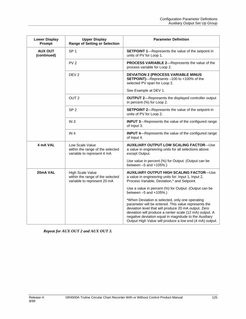
Configuration Parameter DefinitionsAuxiliary Output Set Up Group
Release H DR4500A Truline Circular Chart Recorder With or Without Control Product Manual 1258/99
Lower DisplayPrompt
Upper DisplayRange of Setting or Selection
Parameter Definition
AUX OUT(continued)
SP 1 SETPOINT 1—Represents the value of the setpoint inunits of PV for Loop 1.
PV 2 PROCESS VARIABLE 2—Represents the value of theprocess variable for Loop 2.
DEV 2 DEVIATION 2 (PROCESS VARIABLE MINUSSETPOINT)—Represents –100 to +100% of theselected PV span for Loop 2.
See Example at DEV 1.
OUT 2 OUTPUT 2—Represents the displayed controller outputin percent (%) for Loop 2.
SP 2 SETPOINT 2—Represents the value of the setpoint inunits of PV for Loop 2.
IN 3 INPUT 3—Represents the value of the configured rangeof Input 3.
IN 4 INPUT 4—Represents the value of the configured rangeof Input 4.
4 mA VAL Low Scale Valuewithin the range of the selectedvariable to represent 4 mA
AUXILIARY OUTPUT LOW SCALING FACTOR—Usea value in engineering units for all selections aboveexcept Output.
Use value in percent (%) for Output. (Output can bebetween –5 and +105%.)
20mA VAL High Scale Valuewithin the range of the selectedvariable to represent 20 mA
AUXILIARY OUTPUT HIGH SCALING FACTOR—Usea value in engineering units for: Input 1, Input 2,Process Variable, Deviation,* and Setpoint.
Use a value in percent (%) for Output. (Output can bebetween –5 and +105%.)
*When Deviation is selected, only one operatingparameter will be entered. This value represents thedeviation level that will produce 20 mA output. Zerodeviation will produce a center scale (12 mA) output. Anegative deviation equal in magnitude to the AuxiliaryOutput High Value will produce a low end (4 mA) output.
Repeat for AUX OUT 2 and AUX OUT 3.

Configuration Parameter DefinitionsModbus Communications Set Up Group
126 DR4500A Truline Circular Chart Recorder With or Without Control Product Manual Release H 8/99
4.14 Modbus Communications Set Up Group
Introduction
This option allows the DR4500A to be connected to a host computer via the Modbus protocol. Up to 99addresses and a maximum of 15 units can be configured over this link.
REFERENCE
Refer to Documents 51-52-25-66 and 51-52-25-69 for a complete description of the RS485Modbus Communications Option.
Communications group prompts
Table 4-14 lists all the function prompts in the Modbus Communications set up group and their functions.
Table 4-14 Modbus Communications Group Definitions
Lower DisplayPrompt
Upper DisplayRange of Setting or Selection
Parameter Definition
ComSTATE DISABLMODBUS
DISABL—Disables the communications option.MODBUS—Allows Modbus communication prompts.
Com ADDR 1 to 99 COMMUNICATIONS STATION ADDRESS — This is anumber that is assigned to the recorder that is to beused with the communications option.
BAUD
30060012002400480096001920038400
BAUD RATE is the transmission speed in bits persecond.
300 Baud600 Baud1200 Baud2400 Baud4800 Baud9600 Baud19200 Baud38400 Baud
XMT DLAY NONE10MSEC20MSEC30MSEC40MSEC50MSEC
TRANSMIT DELAY—This is the approximate timedelay between receipt of Modbus request message andstart of response message (in addition to messageprocessing time).

Configuration Parameter DefinitionsOptions Set Up Group
Release H DR4500A Truline Circular Chart Recorder With or Without Control Product Manual 1278/99
4.15 Options Set Up Group
Introduction
The Options Set Up Group lets you enable or disable some of the options that are available on the DR4500.You can select the power frequency, select relative humidity as a measurement and a atmospheric pressurecompensation, select deviation recording action, and set the desired deviation setpoint.
Options group prompts
Table 4-15 lists all the function prompts in the Option set up group and their functions.
Table 4-15 Option Group Definitions
Lower DisplayPrompt
Upper DisplayRange of Setting or Selection
Parameter Definition
REJ FREQ 60HZ50HZ
REJECTION FREQUENCY – be sure that this selectionagrees with the line voltage frequency.
HF REJ ENABLEDISABL
HIGH FREQUENCY REJECTION – This selectionallows high frequency noise rejection. It is used to quietnoisy pens or PV.
ATTENTION For fast processes it will causeadditional lag.
RELHUMID NOYES
RELATIVE HUMIDITY – allows you to activate ordeactivate the RH calculation algorithm.
• You must select 100RH input type for two inputs tomeasure RH. It requires two 100-ohm RTD inputs soINPUT 2 must be enabled for this prompt to appear.
• Also, you must select RH for “PEN2IN” whichrepresents the “wet bulb” temperature when input 2 isselected.
ATMPRES 590 to 800 mmHg ATMOSPHERIC PRESSURE COMPENSATION – Thisprompt only appears if you select “YES” at “RELHUMID”prompt previously. Select the desired compensation.
DEVIATION
NONE
SETPNT
CHAN1
DEVIATION – selects deviation recording action.
• NONE – No deviation recording
• SETPNT – Records deviation from setpoint
• CHAN1 – Pen 1 records the difference between Input1 and Input 2.
DEVSETPT –999.0 to 9999 DEVIATION SETPOINT VALUE – sets the desireddeviation setpoint value for deviation recording.
• This prompt only appears if “SETPNT” was selectedat prompt “DEVIATION” previously.

Configuration Parameter DefinitionsOptions Set Up Group
128 DR4500A Truline Circular Chart Recorder With or Without Control Product Manual Release H 8/99
Lower DisplayPrompt
Upper DisplayRange of Setting or Selection
Parameter Definition
SCROLL LOWER DISPLAY SCROLL—The lower display willautomatically change to the next item (as if theLOWR DISP key had been pressed) at the intervalselected.
NONE NONE—Disables the scroll function.
1 SEC 1 SEC—One second intervals
2 SEC 2 SEC—Two second intervals
3 SEC 3 SEC—Three second intervals
GRANDTOT ENABLEDISABL
GRAND TOTALIZER—When enabled it prints, on thechart, the sum of ALL the enabled totalizers as
TOTAL = XXXXXXXXXXX.This is printed in the space for totalizer 4. If grand totalis disabled, total 4 on the DR45AW model will printnormally.

Configuration Parameter DefinitionsEvent Message Set Up Group
Release H DR4500A Truline Circular Chart Recorder With or Without Control Product Manual 1298/99
4.16 Event Message Set Up Group
Introduction
This Set Up group allows you to specify six event messages to be printed on a designated area of the chartand triggered by a specific selectable actuation. The message can be six characters long.
Press the FUNC key until the specific event prompt appears in the lower display.
Event Message group prompts
Table 4-16 lists all the function prompts in the Event Message set up group and their definitions.
Table 4-16 Event Message Group Definitions
Lower DisplayPrompt
Upper DisplayRange of Setting or Selection
Parameter Definition
60HZ50HZ
EVENT TRIGGER—Select the triggering source foreach of the six event messages.
NONE NONE—No event message
EXT SW1 EXT SW1—Event triggered by external switch 1 closure
EXT SW2 EXT SW2—Event triggered by external switch 2 closure
ALARM 1 ALARM 1—Event triggered by Alarm 1
ALARM 2 ALARM 2—Event triggered by Alarm 2
ALARM 3 ALARM 3—Event triggered by Alarm 3
ALARM 4 ALARM 4—Event triggered by Alarm 4
ALARM 5 ALARM 5—Event triggered by Alarm 5
EVENT n(n = 1, 2, 3, 4, 5, or
6)
ALARM 6 ALARM 6—Event triggered by Alarm 6
MESSAGEn(n = 1, 2, 3, 4, 5, or
6)
0 to 9A to Z+–/(blank)*
MESSAGE FOR EVENT—Select a message to beprinted when Event is triggered. You can use up to sixcharacters.
*For alphanumeric entries, the display will cycle, fromleft to right, with highlighting (increased brightness) ofeach digit. The value of each digit can be changed onlywhen it is highlighted.
POSITIONn(n = 1, 2, 3, 4, 5, or
6)
0 to 100% CHART POSITION FOR MESSAGE—Select where youwant the message to appear on the chart.
Repeat for all messages required.

Configuration Parameter DefinitionsLockout Parameters Set Up Group
130 DR4500A Truline Circular Chart Recorder With or Without Control Product Manual Release H 8/99
4.17 Lockout Parameters Set Up Group
Introduction
These are the parameters that you will set to lockout any unauthorized changes to the recorder’sconfiguration and calibration prompts. You must know the PASSWORD in order to change the Lockoutconfiguration. Refer to Appendix B for more information on security lockout.
ATTENTION
Configuration can also be locked using S1 switch on the main printed circuit board. Refer toSubsection 2.9 – Configuration Lockout Switch.
This feature also includes the special screw and plate that provide for the lead seal capability for sealing thechart plate.
Set this group last
Because this group contains functions that have to do with security and lockout, we recommend that youconfigure this group last, after all the other configuration data has been loaded.
Lockout group prompts
Table 4-17 lists all the function prompts in the Lockout set up group and their definitions.
Table 4-17 Lockout Group Definitions
Lower DisplayPrompt
Upper DisplayRange of Setting or Selection
Parameter Definition
PASSWORD Select up to four alphanumericcharacters
PASSWORD -- this selection determines the passwordthat will be required to gain access to the lockoutprompt.
• ++++ is the factory default password.
LOCKOUT
NONE
CALIB
+CONF
MAX
LOCKOUT applies to one of the functional groups:Configuration, Calibration, Tuning, Adaptive Tune. DONOT CONFIGURE UNTIL ALL CONFIGURATION ISCOMPLETE.
• If the correct password was entered, you can call upthis prompt.
No Lockout – all groups read/write.
CALIB – All are available for read/write except for theCalibration group.
+CONF – Tuning, SP Ramp and program groups areread/write. All other groups are read only. Calibrationgroup is not available.
MAX – Calibration group not available. All other groupsare Read-only.
ATTENTION Do not leave in “NONE” Lockout.
CHANGE Selections are:0 to 9A to Z
CHANGE PASSWORD – Changes default password toone of your own.Be sure to record the new password in a safe location.

Configuration Parameter DefinitionsPrinting Characteristics Adjustments
Release H DR4500A Truline Circular Chart Recorder With or Without Control Product Manual 1318/99
4.18 Printing Characteristics Adjustments
Introduction
With software version 1005 (and newer), two different hot stylus pen designs are available; check yourmodel number for:
Table III = _0_ for high speed stylus 30756304-001 (black tip)
Table III = _1_ for abrasion resistant jewel tip stylus 30756304-002 (beige tip)
The abrasion resistant stylus is designed for recording applications that include highly abrasiveenvironments. The abrasion resistant stylus should only be used with chart speeds from 24 hrs/revto 31 days/rev.
Configuration choices
Configuration choices are now provided for PEN TYPE and the selection made must match the stylusdesign.
• PEN TYPE = NORMAL is for the high speed stylus design.
• PEN TYPE = JEWEL is used only for abrasion resistant stylus design.
CAUTION
If the “JEWEL” selection is accidentally used with the high-speed design, the life of that styluswill be shortened.
Printing characteristics adjustments
Normally there is no need to adjust the printing characteristics as part of an input or output calibrationprocedure. However, if the chart printing appears to be faded, you can use the procedure in Table 4-18 tomake slight adjustments in the print contrast.
ATTENTION
To access Set-up group prompt “ADJUST”, the Set Up group prompt “LOCKOUT” must be setto “NONE”. If the group prompt “LOCKOUT” has been configured for “CALIB” or “MAX”selection, you will not be able to access the Printing Characteristics Group prompt. Refer toSubsection 4.14 for details.

Configuration Parameter DefinitionsPrinting Characteristics Adjustments
132 DR4500A Truline Circular Chart Recorder With or Without Control Product Manual Release H 8/99
Printing characteristics adjustments procedure
Table 4-18 is the procedure to adjust the printing characteristics of your recorder.
Table 4-18 Printing Characteristics Adjustment Procedure
Step Description Press Action
1 Enter Set Up GroupADJUST
SETUP
Until you see:Upper Display: ADJUSTLower Display: PRINTING)
2 Select Trace LineContrast
FUNC Until you see:Upper Display: DARK, MEDIUM, or LIGHTLower Display: TRACE LN
• Press or to select the desired contrast.
3 Select Grid Line Contrast FUNC Until you see:Upper Display: DARK, MEDIUM, or LIGHTLower Display: GRID LN
• Press or to select the desired contrast..
4 Select Stylus FUNC Until you see:Upper Display: NORMAL or JEWELLower Display: PEN TYPE
• Press or to select the pen type.
• Select “NORMAL” if high speed stylus (black tip) isinstalled.
• Select “JEWEL” only if abrasion resistant stylus(beige tip) is installed.
5 Return to normaloperation
LOWRDISP
Return to normal operation and observe the change inprinting characteristics.
• Change Set Up group “LOCKOUT” to somethingother than “NONE”.

Release H DR4500A Truline Circular Chart Recorder With or Without Control Product Manual 1338/99
5. Operation
5.1 Overview
Introduction
This section gives you all the information necessary to monitor and operate your recorder and forperforming routine maintenance tasks. In this section assume that the recorder has been properly installedand configured, and that the inputs are properly calibrated.
Some of the procedures in this section are required only initially, and some are required only randomly, asconditions dictate. Once the recorder is up and running, required operation actions are infrequent andstraightforward.
Review the Operator Interface, Display and Keypad descriptions shown in Section 1 - Overview.
What’s in this section?
This section contains the following topics:
Topic See Page
5.1 Overview 133
5.2 Start-up 134
5.3 Monitoring Your Recorder 138
5.4 Operator Functions 144
5.5 Operating Modes 145
5.6 Setpoints 147
5.7 Single Setpoint Ramp 149
5.8 Using Two Sets of Tuning Constants (PID Values) 152
5.9 Using Accutune II 155
5.10 Alarm Setpoints 159
5.11 Three Position Step Control Algorithm 160
5.12 Digital Input Option (Remote Switching) 161
5.13 Resetting and Displaying Totalizer Value 162
5.14 Monitoring the External Event Operation 163
5.15 Maximizing Pen Life 164
5.16 Routine Maintenance 165
5.17 Installing/Replacing Chart 166
5.18 Chart Operation 167

OperationStart-up
134 DR4500A Truline Circular Chart Recorder With or Without Control Product Manual Release H 8/99
5.2 Start-up
Preparation
Before start-up, there are two tasks to perform:
• Install or replace the circular chart as described in 5.14 - Routine Maintenance.
• Be sure that the configured settings for the current time and wake time (time at which recording begins)are correct. Note that the recorder is “awake” during start-up to verify interaction with the process.
During start-up, you should verify the interaction between your process and the DR4500A recorder to besure that your process can tolerate some upsets during this procedure.
Diagnostic tests
When power is applied, the recorder will run four diagnostic tests. Table 5-1 lists the four diagnostic tests.
Table 5-1 Power Up Diagnostic Tests
Prompt on Lower Display Condition
RAM TEST Check RAM
CONFTEST (configuration checksum) Check nonvolatile memory
CAL TEST (working calibration) Check calibration
BATTERY Check the battery
Test failures
If control is enabled and one or more of these tests fail, the recorder will go to the Failsafe Manual Mode,and “FAILSAFE” will flash in the lower display.
If control is not configured, the self-test failures will be displayed periodically as other messages arepresently displayed (CNFG ERR, CAL1 ERR, CAL2 ERR, or BATT LOW).
Troubleshooting
Refer to “DEVICE STATUS” in Section 9 - Troubleshooting/Service to identify and correct the problem.

OperationStart-up
Release H DR4500A Truline Circular Chart Recorder With or Without Control Product Manual 1358/99
Check the displays and keys
Use the procedure in Table 5-2 to run the display and key test.
Table 5-2 Procedure for Testing the Displays and Keys
Press Result
SETUP
and hold in, then press
FUNC
at the same time
The recorder runs a display test. All the displays will light for 8seconds, then you will see:
Upper Display: keys
Lower Display: try all
Press each key to see if itworks
When the key is pressed, the lower display indicates the name of thekey pressed.
Key Pressed Lower Display
SET UP SET UP
LOWR DISP LWR DISP
MAN/AUTO AUTO MAN
RESET RESET
CHART CHART
INCRMENT
DECRMENT
RUN/HOLD RUN HOLD
• If no key is pressed for 25 seconds, the test times out and the recorder exits the key test.
• If any test fails, go to subsection 9.3 Self Diagnostics for more information.
Key error
When a key is pressed and the prompt “KEY ERROR” appears in the lower display, it will be for one ofthe following reasons:
• parameter not available,
• not in Set Up mode, press SET UP key first,
• key malfunction, perform keyboard test.
Start-up procedure
Use the procedure listed in Table 5-3 to start up the recorder.
Open the recorder door. Apply power and wait for the recorder to run its power-up tests.

OperationStart-up
136 DR4500A Truline Circular Chart Recorder With or Without Control Product Manual Release H 8/99
ATTENTION
• If FAILSAFE starts blinking in the lower display, refer to Section 9 fortroubleshooting data.
• For recorders with two controllers (both enabled), be sure the CHN ‘1’ indication islit for steps 2-6. If CHN 1 is not lit, sequentially press the LOWR DISP key until “1”is lit when “OUT” is displayed.
Table 5-3 Procedure for Starting Up the Recorder
Step Description Press Action
1 Pen check For RECORDER ONLY models, just check that the penis operating and skip to step 6.
2 Select manual mode MANAUTO
Until “MAN” indicator is ON.The recorder is in manual mode and the Output (OUT)in percent is displayed in the lower display.
3 Adjust the output or Adjust the output value and ensure that the final controlelement is functioning correctly.
Upper Display: shows the PV value
Lower Display: shows OUT and the output valuein %
Make sure the pen trace on the chart corresponds tothe change in output.
4 Tune the recorder SETUP
Make sure the recorder has been configured properlyand all the values and selections have been recordedon the Configuration Record Sheet.
To tune your recorder automatically, see section 5.9Using Accutune II.
Refer to Set Up group TUNING 1 or TUNING 2 toensure that the proper selections for PROP BD orGAIN, RATE MIN, and RSET MIN or RSET RPM havebeen entered.
5 Enter the local setpoint LOWRDISP
Until you see:
Upper Display: shows the PV value
Lower Display: SP and the local setpoint value
or Adjust the local setpoint to the value at which you wantthe process variable maintained.
The local setpoint cannot be changed if the SetpointRamp function is enabled.
“H” or “R” appears in the upper display.
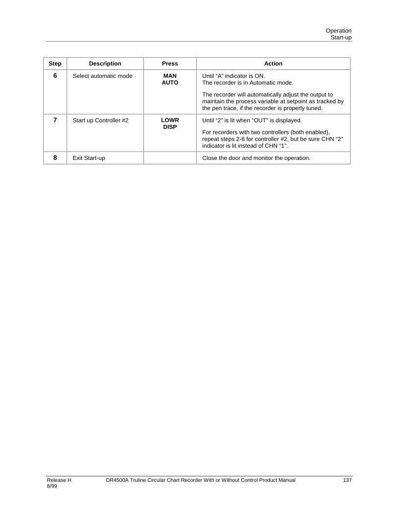
OperationStart-up
Release H DR4500A Truline Circular Chart Recorder With or Without Control Product Manual 1378/99
Step Description Press Action
6 Select automatic mode MANAUTO
Until “A” indicator is ON.The recorder is in Automatic mode.
The recorder will automatically adjust the output tomaintain the process variable at setpoint as tracked bythe pen trace, if the recorder is properly tuned.
7 Start up Controller #2 LOWRDISP
Until “2” is lit when “OUT” is displayed.
For recorders with two controllers (both enabled),repeat steps 2-6 for controller #2, but be sure CHN “2”indicator is lit instead of CHN “1”.
8 Exit Start-up Close the door and monitor the operation.

OperationMonitoring Your Recorder
138 DR4500A Truline Circular Chart Recorder With or Without Control Product Manual Release H 8/99
5.3 Monitoring Your Recorder
Introduction
Besides the historical chart record, you can monitor the recorder’s indicators and displays to get aninstantaneous view of various process conditions and of the control loop status.
Diagnostic error messages signal detection of malfunctions in certain internally monitored data. Alarm andtuning messages indicate alarms in effect and control loops being tuned.
Operator interface
The indicators and displays on the operator interface let you see what is happening to your process and howthe recorder is responding.
Figure 5-1 is a view of the operator interface. A description of the displays and indicators is included.
21401
Control relay 1 or 2 is ON, when lit.
ALM
CHN
RSP
OUT
12 FC
%
FUNC LOWRDISP
MANAUTO
CHART
SET UP
RUNHOLD
MAN
12
Lower Display - eight characters
• Normal operation - Displays selectableoperating parameters and values. Indicatesdiagnostic error messages, alarm conditionfor alarms 3-6, Accutune in progress.• Configuration mode - Displays functiongroup and parameters.
Remote set point or 2nd set point is active, when lit. Blinks when 2nd setpoint or remote setpoint is attained through remote switch
PV displayed is for channel 1, 2, 3, or 4
Alarm condition exists for alarm 1 or 2, when lit.
Indicates temperature units of PV Upper Display - six characters Normal operation - Displays process variable (PV) for selected channels. Configuration mode - Displays selection or parameter value.
Indicates controller mode: MAN = Manual A = Automatic
Bargraph - deviation ( 10% of span) Center green bar indicates PV is within 1% of control setpoint. Next small bar will light if PV is between 1% but less than 2% in deviation. If PV is equal to or greater than 10% deviation, the green bar plus all ten small green bars will light.
+-
+-
+- +-+-
1234
Keypad / Key functions
Figure 5-1 Operator Interface

OperationMonitoring Your Recorder
Release H DR4500A Truline Circular Chart Recorder With or Without Control Product Manual 1398/99
Meaning of indicators
During normal operation, the indicators will light for the reasons shown in Table 5-4.
Table 5-4 Meaning of Indicators
Indicator Definition when lit
ALM 1 2 Alarm condition exists for alarm 1 or 2.*
CHN 1 2 3 4 PV displayed is for channel 1, 2, 3, or 4.
RSP Remote Setpoint (when available) or 2nd setpoint is active.
OUT 1 2 Control relay 1 or 2 is ON.
A or MAN Indicates the mode of operation: A = AutomaticMAN = Manual
F or C or blank Indicates the temperature units of PV: F = FahrenheitC = Celsius
R or H or G or blank(in upper display)
Indicates the state of the setpoint ramp or program if enabled:R = RunH = HoldG = Guar Soakblank = Disabled
T Totalizer
KEY ERR(in lower display)
Indicates parameter not available, not in set up mode, or keymalfunction.
* AL1 indicator can also mean the Interval Timer has timed out. Alarms 3-6 are indicated by a message onthe lower display. See Table 5-7.

OperationMonitoring Your Recorder
140 DR4500A Truline Circular Chart Recorder With or Without Control Product Manual Release H 8/99
Reading the deviation bargraph
In addition to the indicators, a bargraph containing 21 bars displays Process Variable (PV) deviation fromSetpoint (SP).
ATTENTION
When CHN “1” indicator is lit, the bargraph display applies for Controller #1. It applies forController #2 when CHN “2” indicator is lit. Sequentially press the LOWR DISP key to light theappropriate CHN indicator (1 or 2) and view the corresponding controller displays.
• The green “on-control” bar lights when the PV is within ±1% of setpoint.
• The 10 small green bars above the “on-control” bar light for each positive deviation up to +10% and the10 below light for each negative deviation down to –10%. If the process deviation is greater than ±10%,the “on-control” bar and the specific small green bars light.
Figure 5-2 shows how the deviation bargraph works.
+1 to +10% small green deviation bars
21424
-1 to -10% small green deviation bars
Green "on control" bar
Figure 5-2 Deviation Bargraph

OperationMonitoring Your Recorder
Release H DR4500A Truline Circular Chart Recorder With or Without Control Product Manual 1418/99
Viewing the operating parameters
The upper display is a six-character display, four of which show the value of the PV during normaloperation.
• The lower display is an eight-character display. During normal operation, you can view variousoperating parameters. Press the LOWR DISP key to scroll through the operating parameters listed inTable 5-5.
• The lower display shows only those parameters and their values that apply to your specific model andthe way in which it was configured.
• You can configure the lower display to scroll through the items in Table 5-5 at an interval of 1, 2, or 3seconds. Refer to Subsection 3.19 – Options Set Up group, function prompt “SCROLL” to make yourselection.
Pressing the LOWR DISP key will freeze the lower display at the presently viewed item; pressing itagain will advance to the next item and scrolling will resume.
• Pressing ZKLOHSUHVVLQJLOWR DISP will scroll backwards.
For recorders with two controllers (both enabled) remember that any controller-related values displayedcorrespond with the lighted CHN indicator — “1” means that the values apply for Controller #1 and “2”means that the values apply for Controller #2.
Table 5-5 Lower Display Key Parameter Prompts
Prompt Description
OUT** Output Value in Percent (%). Note that the output can only be adjusted through theraise/lower keys when the controller in manual mode. (Estimated motor position for3 Position Step Control)
SP** Local Setpoint 1. Also current setpoint of SP Ramp, or SP Ramp/Soak Program.
SPN Current setpoint for setpoint rate applications.
2SP** Local Setpoint 2 (where remote setpoint does not apply)
RSP Remote Setpoint (when configured)
1IN Value of Channel 1 input (if Loop1 is a derived PV)
2IN Value of Channel 2 input (when available)
3IN Value of Channel 3 input (when available)
4IN Value of Channel 4 input (when available)
DEV PV deviation from setpoint (±999.9 maximum)
EU Engineering units that PV represents (when available)
RH RH value in percent (%) (when available)
PIDSETx** Tuning Parameter Set x =1 or 2
RAMP The time (minutes) remaining in the setpoint ramp
#RA The time (minutes) remaining in the SP Ramp segment
#SK The time (minutes) remaining in the SP Soak segment
RECYC The number of recycles remaining to be run in the Setpoint Program

OperationMonitoring Your Recorder
142 DR4500A Truline Circular Chart Recorder With or Without Control Product Manual Release H 8/99
Prompt Description
** Time remaining in Timer function
** Time elapsed in Timer function
TUNExXXX** Accutune II indicator. x = Loop number (1 or 2). XXX = ON or OFF.
**You can press or to change the value of this parameter.
Diagnostic error messages
The DR4500A runs background tests to verify data and memory integrity. If there is a malfunction, an errormessage will blink in the lower display.
In the case of more than one simultaneous malfunction or alarm, each message will be shown in succession.
A list of error messages is contained in Table 5-6. If any of these error messages occur, refer to Section 9 -Troubleshooting/Service for information to correct the failure.
Table 5-6 Error Messages
Prompt Description
EE FAIL Unable to write to nonvolatile memory
FAILSAFE Failsafe
INP1FAIL Two consecutive failures of input 1 integration
INP2FAIL Two consecutive failures of input 2 integration
INP3FAIL Two consecutive failures of input 3 integration
INP4FAIL Two consecutive failures of input 4 integration
INP1 RNGINP2 RNGINP3 RNGINP4 RNG
Input out-of-range
PV LIMIT PV ±10% out-of-range
RV LIMIT Remote Variable out-of-rangeNote: RV = (input 2 x ratio) + bias
CNFG ERR Configuration data is in error.
CAL1 ERR Working CAL TEST failure (Control Output #1, Input 1, Input 2)
CAL2 ERR Working CAL TEST failure (Control Output #2, Input 3, Input 4)
BATT LOW Battery failure

OperationMonitoring Your Recorder
Release H DR4500A Truline Circular Chart Recorder With or Without Control Product Manual 1438/99
Alarm and tuning messages
Alarms #3 through #6 and Accutune II for Control Loops #1 and #2 are indicated in the lower display.
In the case of more than one simultaneous diagnostic or alarm message, each message will be shown insuccession.
Table 5-7 Alarm and tuning messages
Prompt Description
ALARM 3 Indicates an alarm 3 action.
ALARM 4 Indicates an alarm 4 action.
ALARM 5 Indicates an alarm 5 action.
ALARM 6 Indicates an alarm 6 action.
TUNING 1 Indicates Accutune II in progress for Control Loop 1.
TUNING 2 Indicates Accutune II in progress for Control Loop 2.
ATTENTION
An active alarm will always provide an indication on the display but may not control itsassociated relay; that is, a higher priority function such as a control loop or timer may havecontrol of the relay.

OperationOperator Functions
144 DR4500A Truline Circular Chart Recorder With or Without Control Product Manual Release H 8/99
5.4 Operator Functions
Actions an operator can initiate
An operator can do the following:
• Change the Control Mode (Auto/Man)
• Adjust the Output Manually
• Change the Setpoint
• Switch between Setpoints
• Run or Disable a Setpoint Ramp
• Run or Disable a Setpoint Program
• Switch between Two Sets of PID Values
• Run or Disable Control Loop Tuning
• Check the Alarm Setpoints
• Reset the Totalizer
• Run a Key Test
Note that some actions depend upon how the recorder was configured and the features supplied on yourparticular recorder model.
Refer to the following pages for functions and procedures.
CHN indicator
Remember, for recorders with two controllers (both enabled) remember that any controller-related valuesdisplayed, including control mode, correspond with the lighted CHN indicator — “1” means that the valuesapply for Controller #1 and “2” means that the values apply for Controller #2. Sequentially press theLOWR DISP key to scroll through the displays and light the appropriate CHN indicator for controller-related values.

OperationOperating Modes
Release H DR4500A Truline Circular Chart Recorder With or Without Control Product Manual 1458/99
5.5 Operating Modes
Available modes
The recorder can operate in any of three basic modes:
• Manual
• Automatic with Local Setpoint
• Automatic with Remote Setpoint
Manual and Automatic with Local setpoint are standard features and Automatic with Remote Setpoint isoptional.
Mode definitions
Table 5-8 Operating Mode Definitions
Operating Mode Definition
MANUAL When switched to manual mode, the recorder holds its output at the lastvalue used during automatic operation and stops adjusting the output forchanges in setpoint or process variable.Instead, you adjust the output by changing the value shown in the lowerdisplay. See “Selecting Modes”.
AUTOMATIC withLOCAL SETPOINT
In automatic local mode, the recorder operates from the local setpoint andautomatically adjusts the output to maintain the setpoint at the desiredvalue.In this mode you can adjust the setpoint. See “Setpoints”.
AUTOMATIC withREMOTE SETPOINT
In automatic remote mode, the recorder operates from the setpointmeasured at input 2.Adjustments are available to ratio this input and add a constant biasbefore it is applied to the control equation. See subsection 3.12 ControlSet Up Group.
What happens when you change modes
Table 5-9 explains what happens to the recorder when you switch from one mode to another.
Table 5-9 Changing Operating Modes
Operating Mode Definition
Manual to AutomaticLocal Setpoint
The local setpoint is usually the value previously stored as the localsetpoint.
Manual or Auto Local toAutomatic Remote SP
The second input value with ratio and bias applied is used to calculate thecontrol setpoint.
Automatic Remote SP toManual or Auto LocalSetpoint
If configured for RSP Tracking, when the recorder transfers out of remotesetpoint, the last value of the control setpoint is inserted into the localsetpoint.If RSP tracking is not configured, the local setpoint will not be alteredwhen the transfer is made.

OperationOperating Modes
146 DR4500A Truline Circular Chart Recorder With or Without Control Product Manual Release H 8/99
Selecting manual or automatic mode
An alternate action switch places the recorder in automatic or manual mode of operation.
• Switching between manual and automatic will be bumpless, except when the PD+MR algorithm isselected.
• Table 5-10 includes procedures for selecting automatic or manual mode and changing the output whilein manual.
Table 5-10 Procedure for Selecting Automatic or Manual Mode
Step Operation Press Action/Result
1 Selecting automaticmode
MANAUTO
Until “A” indicator is ON.The recorder regulates its output to maintain the PV atthe desired setpoint.
Upper Display: shows the PV value
Lower Display: shows SP and the setpoint value
The deviation bargraph indicates the PV deviation fromthe setpoint.
2 Selecting manual mode MANAUTO
Until “MAN” indicator is ON.The recorder holds its output at the last value usedduring automatic operation and stops adjusting theoutput for changes in setpoint or process variable.
Upper Display: shows the PV value
Lower Display: shows OUT and the output valuein %
The deviation bargraph indicates the PV deviation fromthe setpoint.
3 Adjust the output inmanual mode
or Adjust the output value while in manual mode.
Upper Display: shows the PV value
Lower Display: shows OUT and the output valuein %
4 Return to automaticmode
MANAUTO
“A” indicator appears indicating automatic mode.
Position proportional backup mode
This feature provides for Position Proportional models to automatically change to a Three Position Stepalgorithm if the slidewire input signal fails. This will maintain control of your process.
“SWFAIL” or “SW2FAIL” will flash in the lower display and the “OUT” display will show an estimatedmotor position WITHOUT a decimal point.

OperationSetpoints
Release H DR4500A Truline Circular Chart Recorder With or Without Control Product Manual 1478/99
5.6 Setpoints
Introduction
You can configure the following setpoints for the DR4500A recorder.
• A single local setpoint
• 2 local setpoints
• A local setpoint and a remote setpoint
• A computer setpoint.
These setpoints can be toggled by the FUNC key.
Selecting the setpoint source
Use the procedure in Table 5-11 to select a single local setpoint source, a remote setpoint source, or twolocal setpoints.
Table 5-11 Procedure for Selecting the Setpoint Source
Step Operation Press Action/Result
1 Enter set up mode SETUP
Until the displays read:Upper Display: SET UPLower Display: CONTROL
2 Display local setpointsource selections
FUNC Until the displays read:Upper Display: Setpoint source selections
1LOCAL2LOCALREMOTE
Lower Display: SP SOURCE
3 Select the desired source or Select the desired setpoint source in the upper display.
4 Return to control LOWRDISP
Controller assumes normal control.
Changing the local setpoints
Use the procedure in Table 5-12 to change either local setpoint value.
Table 5-12 Procedure for Changing the Local Setpoint
Step Operation Press Action/Result
1 Select the setpoint LOWRDISP
Until you see:Upper Display: PV valueLower Display: SP or SP2 and the local setpoint
value
2 Change the value or Change the local setpoint to the value at which youwant the process maintained. The deviation bargraphindicates PV deviation from setpoint.

OperationSetpoints
148 DR4500A Truline Circular Chart Recorder With or Without Control Product Manual Release H 8/99
Switching between setpoints
You can switch between Local and Remote setpoints or between two Local setpoints when configured. Usethe procedure in Table 5-13 to switch between setpoints.
Table 5-13 Procedure for Switching Between Setpoints
Step Operation Press Action/Result
1 Switch between setpoints FUNC
or
LOWRDISP
Alternately select Local setpoint 1 and Remote setpointor switch between the 2 Local Setpoints.or
Press appropriate key until you see the desired setpointindicated.
ATTENTION “KEY ERROR” appears in the lowerdisplay if the remote setpoint or second local setpoint isnot configured as a setpoint source, or if you attempt tochange the setpoint while a setpoint ramp is enabled.
2 Change the Localsetpoint value
or The REMOTE setpoint cannot be changed at thekeyboard.
Setpoint selection indication
Table 5-14 shows how the indicators react and what the displays show for each type of setpoint.
Table 5-14 Setpoint Selection Indication
Using Local Setpoint Using Remote Setpoint Using 2nd Local Setpoint
RSP Indicator OFF ON (Note 1) ON (Note 2)(Note 3)
Upper Display PV PV PV
Lower Display SP and the Local SetpointSource
RSP and Remote SetpointValue
2SP and the 2nd LocalSetpoint Value
To ChangeSetpoint Value
Press or Cannot change the value atthe keyboard.
Press or
Note 1—RSP blinks when RSP is reached using Digital InputNote 2—RSP solid for 2nd SetpointNote 3—RSP blinks for 2nd setpoint activated by Digital Switch

OperationSingle Setpoint Ramp
Release H DR4500A Truline Circular Chart Recorder With or Without Control Product Manual 1498/99
5.7 Single Setpoint Ramp
Configuring the setpoint ramp
You can configure a single setpoint ramp to occur between the current local setpoint and a final localsetpoint over a time interval of from 1 to 255 minutes. You can RUN or HOLD the ramp at any time.
Procedure
Table 5-15 lists the procedure for configuring the Setpoint Ramp 1 or 2 parameters. The procedure forSetpoint Program is in Section 6 – Setpoint Ramp/Soak Programming Option.
Table 5-15 Procedure for Configuring a Single Setpoint Ramp
Step Operation Press Action/Result
1 Select SP RAMP 1 orSP RAMP 2 Set Upgroup
SETUP
Until you see:
Upper Display: SET UP
Lower Display: SP RAMP XX = 1 or 2
2 Select the Setpoint Rampfunction
FUNC Until you see:
Upper Display: DISABL
Lower Display: SP RAMP X
3 Enable Setpoint Ramp Until you see:
Upper Display: ENABLE
Lower Display: SP RAMP X
NOTE: You cannot change the current local setpoint ifthe setpoint ramp function is enabled. Make sure SPPROG is disabled.
4 Set the Ramp Time FUNC Until you see:
Upper Display: The ramp time in minutes
Lower Display: TIME MIN
or Change the upper display value to the number ofminutes in which you want the final setpoint to bereached.
Setting Range = 1 to 255 minutes
NOTE: Entering “0” implies an immediate step changeto the final SP.
5 Set the Final Setpointvalue
FUNC Upper Display: The final setpoint value
Lower Display: FINAL SP
6 or Change the upper display value to the desired finalsetpoint value.
Setting Range = within the setpoint limits

OperationSingle Setpoint Ramp
150 DR4500A Truline Circular Chart Recorder With or Without Control Product Manual Release H 8/99
Running the setpoint ramp
Running a setpoint ramp includes starting, holding, viewing the ramp time, ending the ramp and disablingit.
Procedure
Table 5-16 lists the procedure for running the setpoint ramp.
Table 5-16 Procedure for Running a Setpoint Ramp
Step Operation Press Action/Result
1 Put the controller intoautomatic mode
MANAUTO
Until “A” indicator is ON and you will see:
Upper Display: H and the PV valueLower Display: SP and the present setpoint value
2 Set Start SP or Until the start setpoint value you desire is indicated inthe lower display:
Upper Display: H and the PV valueLower Display: SP and the start setpoint value
3 Start the ramp RUNHOLD
You will see:
Upper Display: R and the PV valueLower Display: SP and a changing setpoint value
NOTE: The value in the lower display will be increasingor decreasing toward the final setpoint value.
The PV value in the upper display and the pen trace willalso change.
4 Hold the ramp at thecurrent value
RUNHOLD
This holds the ramp at the current setpoint value.
Press again to continue run.
A “KEY ERROR” prompt appears if RUN/HOLD key ispressed while “SP RAMP” is disabled.
5 View the remaining ramptime
LOWRDISP
Until you see:
Upper Display: R or H and the PV valueLower Display: RAMP XXXM (time remaining)
6 End the ramp When the final setpoint is reached, the “R” changes to“H” in the upper display and the recorder operates atthe new setpoint.
ATTENTION Any time the local setpoint is differentfrom the final setpoint value and the RUN/HOLD key ispressed — the ramp will start again.

OperationSingle Setpoint Ramp
Release H DR4500A Truline Circular Chart Recorder With or Without Control Product Manual 1518/99
Step Operation Press Action/Result
7 Disable the setpoint rampfunction
SETUP
Until you see:
Upper Display: SET UPLower Display: SP RAMP X
FUNC You will see:
Upper Display: ENABLELower Display: SP RAMP X
You will see:
Upper Display: DISABLLower Display: SP RAMP X
8 Return to normaloperating mode
LOWRDISP
Returns to normal operating mode.

OperationUsing Two Sets of Tuning Constants (PID Values)
152 DR4500A Truline Circular Chart Recorder With or Without Control Product Manual Release H 8/99
5.8 Using Two Sets of Tuning Constants (PID Values)
Introduction
You can use two sets of tuning constants for single output types and choose the way they are to beswitched.
The sets can be:
• Keyboard selected
• Automatically switched when a predetermined Process Variable value is reached.
• Automatically switched when a predetermined Setpoint value is reached.
The following procedures show you how to:
• Select two sets
• Set the switchover value
• Set tuning constant value for each set
• Switch between two sets via the keyboard (without automatic switchover)
ATTENTION
For recorders with two controllers (both enabled) remember that any controller-related valuesdisplayed correspond with the lighted CHN indicator — “1” means that the values apply forController #1 and “2” means that the values apply for Controller #2.
Select two sets
The procedure in Table 5-17 tells you how to select two sets of tuning constants.
Table 5-17 Procedure for Selecting Two Sets of Tuning Constants
Step Operation Press Action/Result
1 Select Control Set Upgroup
SETUP
Until you see:
Upper Display: SET UPLower Display: CONTROL
2 SelectPID SETS function
FUNC You will see:
Upper Display: Available selections are—1 ONLY – 1 set of constants2 KEYBD – 2 sets, keyboard selectable2 PVSW – 2 sets, auto switch at PV value2 SPSW – 2 sets, auto switch at SP value
Lower Display: PIDSETS
or Select the type of PID set.
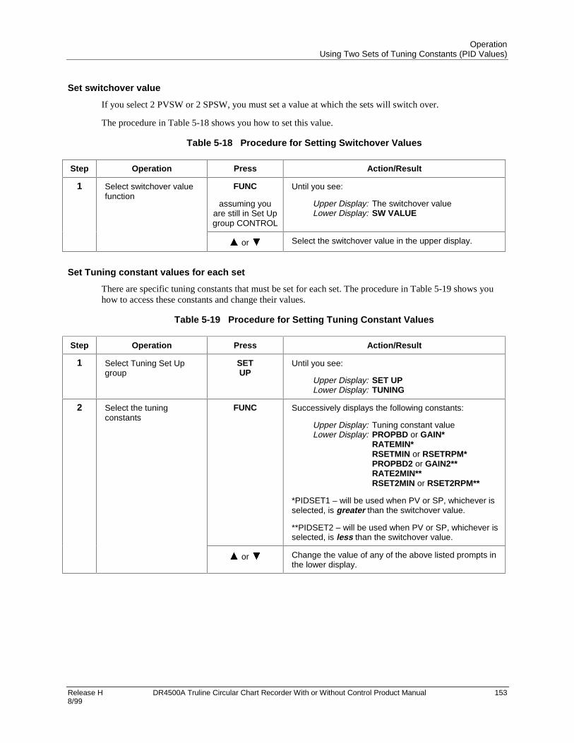
OperationUsing Two Sets of Tuning Constants (PID Values)
Release H DR4500A Truline Circular Chart Recorder With or Without Control Product Manual 1538/99
Set switchover value
If you select 2 PVSW or 2 SPSW, you must set a value at which the sets will switch over.
The procedure in Table 5-18 shows you how to set this value.
Table 5-18 Procedure for Setting Switchover Values
Step Operation Press Action/Result
1 Select switchover valuefunction
FUNC
assuming youare still in Set Upgroup CONTROL
Until you see:
Upper Display: The switchover valueLower Display: SW VALUE
or Select the switchover value in the upper display.
Set Tuning constant values for each set
There are specific tuning constants that must be set for each set. The procedure in Table 5-19 shows youhow to access these constants and change their values.
Table 5-19 Procedure for Setting Tuning Constant Values
Step Operation Press Action/Result
1 Select Tuning Set Upgroup
SETUP
Until you see:
Upper Display: SET UPLower Display: TUNING
2 Select the tuningconstants
FUNC Successively displays the following constants:
Upper Display: Tuning constant valueLower Display: PROPBD or GAIN*
RATEMIN*RSETMIN or RSETRPM*PROPBD2 or GAIN2**RATE2MIN**RSET2MIN or RSET2RPM**
*PIDSET1 – will be used when PV or SP, whichever isselected, is greater than the switchover value.
**PIDSET2 – will be used when PV or SP, whichever isselected, is less than the switchover value.
or Change the value of any of the above listed prompts inthe lower display.

OperationUsing Two Sets of Tuning Constants (PID Values)
154 DR4500A Truline Circular Chart Recorder With or Without Control Product Manual Release H 8/99
Switch between two sets via the keyboard (without automatic switchover)
This procedure is operational only if 2 PID SETS was configured at “CONTROL” set up group.
The procedure in Table 5-20 shows you how to switch from one set to another.
Table 5-20 Procedure for Switching PID Sets from the Keyboard
Step Operation Press Action/Result
1 Access the PID setdisplay
LOWRDISP
Until you see:
Upper Display: The PV valueLower Display: PIDSETX
X = 1 or 2
or Change PIDSET1 to PIDSET2 or vice versa.

OperationUsing Accutune II
Release H DR4500A Truline Circular Chart Recorder With or Without Control Product Manual 1558/99
5.9 Using Accutune II
Introduction
Accutune II provides foolproof, trouble-free on-demand tuning in the recorder. No knowledge of theprocess is required at start-up. The operator simply enters the desired setpoint and initiates the tuning. Therecorder immediately starts controlling to the setpoint while it identifies the process, calculates the tuningconstants and enters them into the tuning set up group, and begins PID control with the correct tuningparameters. This works with any process, including integrating type processes, and allows retuning at afixed setpoint. The tuning sequence will cycle the recorder’s output two full cycles between 0% and 100%(or low and high output limits) while allowing only a very small process variable change above and belowthe setpoint during each cycle.
• Accutune works for all control algorithms except ON/OFF.
• The recorder must be in Auto mode.
• Accutune works for integrating processes.
Enable/disable Accutune using the tuning set up group TUNE parameter described in Section 4.
Detailed instructions for using Accutune follow.

OperationUsing Accutune II
156 DR4500A Truline Circular Chart Recorder With or Without Control Product Manual Release H 8/99
Starting and Stopping Tuning with Accutune II
After “TUNE” has been enabled in the tuning set up group as described in Section 4, use the procedure inTable 5-21 to start tuning.
To abort tuning in progress, press the MAN/AUTO/RESET key to take the recorder out of Auto mode.The message “AbRT” (abort) will be displayed as the value of tuning set up group parameter “AT ERR”.The tuning parameters will retain the values they had at the start of the Accutune operation.
Table 5-21 Procedure for Starting Accutune II
Step Press Action/Result
1 DISPuntil you see
Until you seeLower Display: TuneOF
If “TuneOF” (tune off) does not appear, then Accutune is notenabled.
2
or
to toggle to
Lower Display: TuneON
Tuning will begin and the lower display will flash “TUNING”.When tuning has been ompleted the lower display will again show“TuneOF”.

OperationUsing Accutune II
Release H DR4500A Truline Circular Chart Recorder With or Without Control Product Manual 1578/99
Using Accutune with Duplex (Heat/Cool) Control
“TUNE” can be done for applications using Duplex (Heat/Cool) control.
During tuning, Accutune II assumes SP 1 will cause a Heating demand, and then the calculated tuningparameters will be automatically entered as the first set of PID constants. Likewise, it assumes tuning atLocal SP 2 will cause a Cooling demand, and the cooling parameters will be entered as the second set ofPID constants.
Procedure
After “TUNE” has been enabled in the tuning set up group as described in section 4, use the procedure inTable 5-22 to start tuning. Note that control group parameter “SP SOURC” must be set to “2LOCAL” toenable the second setpoint.
To abort tuning in progress, press the MAN/AUTO/RESET key to take the recorder out of Auto mode.The message “AbRT” (abort) will be displayed as the value of tuning set up group parameter “AT ERR”.The tuning parameters will retain the values they had at the start of the Accutune operation.
Table 5-22 Procedure for Using Accutune for Duplex Control
Step Press Action/Result
Heating Tuning
1 DISP Until you see Setpoint 1.Lower Display: SP nnn
2
or
Until the value of Setpoint 1 is at the desired value within the Heatzone.
Make sure the recorder is in Auto mode. (“A” indicator lit.)If not, use the MAN/AUTO/RESET key to put the unit in Auto.
3 DISP Until you seeLower Display: UseSPn
This is the prompt used to select the setpoint. If it is not“USESP1”, use or to switch to “USESP1”.
4 DISP Until you seeLower Display: TuneOF
If “TuneOF” (tune off) does not appear, then Accutune is notenabled.
5
or
to toggle toLower Display: TuneON
Tuning will begin and the lower display will flash “TUNING”. Theoutput will cycle between 50% and 100% (or high output limit).When tuning has been completed the lower display will againshow “TuneOF”. The Heat tuning parameters are entered for thefirst set of PID constants in the tuning set up group.
Cooling Tuning
6 DISP Until you see Setpoint 2.Lower Display: SP nnn

OperationUsing Accutune II
158 DR4500A Truline Circular Chart Recorder With or Without Control Product Manual Release H 8/99
Step Press Action/Result
7
or
Until the value of Setpoint 2 is at the desired value within theCooling zone.
8 DISP Until you see
Lower Display: Use SP1
9
or
to toggle to
Lower Display: Use SP2
10 DISP Lower Display: TuneOF
11
or
to toggle to
Lower Display: TuneON
Tuning will begin and the lower display will flash “TUNING”. Theoutput will cycle between 0% and 50% (or low output limit). Whentuning has been completed the lower display will again show“TuneOF”. The Cool tuning parameters are entered for thesecond set of PID constants in the tuning set up group.

OperationAlarm Setpoints
Release H DR4500A Truline Circular Chart Recorder With or Without Control Product Manual 1598/99
5.10 Alarm Setpoints
Introduction
• An alarm consists of a relay contact and an operator interface indication. The alarm relay is de-energizedif Alarm Setpoint 1 or Setpoint 2 is exceeded.
• The alarm relay is energized when the monitored value goes into the allowed region by more than thehysteresis.
• There are twelve alarm setpoints, two for each alarm.
• The type and state (High or Low) is selected during configuration: see Section 3 - Configuration fordetails.
ATTENTION
An active alarm will always provide an indication on the display but may not control the relay;that is, a higher priority function such as a control loop or timer may have control of the relay.
Procedure for displaying the alarm setpoints
The procedure for displaying and changing the alarm setpoints is listed in Table 5-23.
Table 5-23 Procedure for Displaying or Changing the Alarm Setpoints
Step Operation Press Action/Result
1 Access the Alarm Set Upgroup
SETUP
Until you see:
Upper Display: SET UPLower Display: ALARM X
X = 1, 2, 3, 4, 5, 6
2 Access the AlarmSetpoint Values
FUNC Successively displays the alarm setpoints and theirvalues.
Upper Display: The alarm setpoint valueLower Display: AXS1 VAL – Setpoint 1 value of
alarm 1, 2, 3, 4, 5, or 6AXS2 VAL – Setpoint 2 value of alarm 1, 2, 3, 4, 5, or 6
or Change any alarm setpoint value you select in theupper display.
3 Return to normaloperation
LOWRDISP
Returns to normal operation.

OperationThree Position Step Control Algorithm
160 DR4500A Truline Circular Chart Recorder With or Without Control Product Manual Release H 8/99
5.11 Three Position Step Control Algorithm
Introduction
The Three Position Step Control algorithm allows the control of a valve (or other actuator) with an electricmotor driven by two controller output relays; one to move the motor upscale, the other to move itdownscale, without a feedback slidewire linked to the motor shaft.
Estimated motor position
The Three Position Step Control algorithm provides an output display (“OUT”) which is an estimatedmotor position since the motor is not using any feedback.
Although this output indication is only accurate to a few percent, it is corrected each time the controllerdrives the motor to one of its stops (0% or 100%).
It avoids all the control problems associated with the feedback slidewire (wear, dirt, noise).
When operating in this algorithm, the estimated “OUT” display is shown to the nearest percent (i.e., nodecimal).
Displaying the motor position
Table 5-24 lists the procedure for displaying the motor position.
Table 5-24 Procedure for Displaying the 3PSTEP Motor Position
Step Operation Press Action/Result
1 Access the displays LOWRDISP
Until you see:
Upper Display: The PV valueLower Display: OUT
Estimated 3PStep motor position
Power up output
When the controller powers up after a power outage, the position of the motor will correspond to whateverwas configured at set up group prompt “CONTROL”, function prompt “PWR OUT”, selection LAST orFAILSAFE. Refer to Subsection 4.8, Table 4-7 for definition of each selection.

OperationDigital Input Option (Remote Switching)
Release H DR4500A Truline Circular Chart Recorder With or Without Control Product Manual 1618/99
5.12 Digital Input Option (Remote Switching)
Introduction
The digital input option detects the state of external contacts wired to it. On contact closure, the controllerresponds according to how each digital input is configured.
• Make your selection under Set Up group “CONTROL1” or “CONTROL2”, function group prompt“REM SW”: see Subsection 3.12—Table 3-9 or Subsection 4.8—Table 4-7.
Action on contact closure
Table 5-25 lists the configuration prompt selections, the “Action on Contact Closure”, and the displayindication for each selection available.
Table 5-25 Digital Input Option Action on Contact Closure
REM SWSelections
Display Indication Action on Contact Closure
None None No Digital Input selection
To MAN “MAN” blinks Puts the controller into manual mode; contact openreturns the controller to former mode unlessAUTO/MAN key is pressed while digital input is active.
To LSP “RSP” blinks Puts the controller into local setpoint 1(switches out ofremote). When contact opens, the controller returns toformer operation unless the FUNC key is pressed whiledigital input is active.
To 2SP “RSP” blinks Puts the controller into local setpoint 2.
To DIR None Selects direct controller action, (transfer if in reverse).
RN/HOLD “H” blinks in upper display Suspends setpoint program or setpoint ramp.
• Keyboard takes priority over external switch forRUN/HOLD function.
• Contact open runs the program or ramp.
• If initially in the HOLD state, close then open thecontact to remotely start the SP ramp or Program
TUNE TUNING x Initiates Accutune
Keyboard operation
If a particular mode or parameter is selected by the contact closure, using the keyboard to select the sameparameter ensures that the selected mode will be maintained after the remote digital switch is reopened.

OperationResetting and Displaying Totalizer Value
162 DR4500A Truline Circular Chart Recorder With or Without Control Product Manual Release H 8/99
5.13 Resetting and Displaying Totalizer Value
Introduction
If the totalizer is enabled and has been configured to allow resetting, you can reset the current totalizervalue as follows.
• Refer to Section 3 - Configuration, under Set-up prompt “TOTAL 1” for Input #1 or “TOTAL 2” forInput #2 to enable the totalizer function and allow the totalizer to be reset.
• Refer to the procedures that follow to:
− reset the totalizer locally,
− reset the totalizer externally (switch),
− display the totalizer value.
Resetting the totalizer
Follow the procedure in Table 5-26 to reset the totalizer value.
Table 5-26 Procedure for Resetting the Totalizer
Step Operation Press Action/Result
1 Access the Totalizer SetUp group
SETUP
Until you see:
Upper Display: SET UPLower Display: TOTAL 1 or TOTAL 2
2 Allow Totalizer Reset FUNC
once
You will see:
Upper Display: Ex XXXLower Display: (a value)
FUNC
again
You will see:
Upper Display: NOLower Display: RSET TOT
or Change NO to YES in the upper display.
ATTENTION Function prompt “RSETABLE” mustbe set to “LOCAL”.
3 Return to normaloperation
LOWRDISP
Returns to normal operation.
External totalizer reset
The totalizer can be reset to “0” from external switch #1 or external switch #2. Refer to Subsection 3.10 –Totalizer Set Up Group and set function prompt “RSETABLE” to “EXT SW1” or “EXT SW2”.
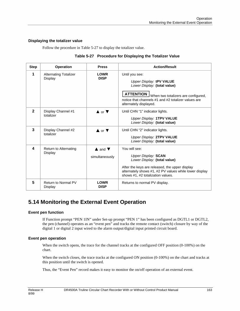
OperationMonitoring the External Event Operation
Release H DR4500A Truline Circular Chart Recorder With or Without Control Product Manual 1638/99
Displaying the totalizer value
Follow the procedure in Table 5-27 to display the totalizer value.
Table 5-27 Procedure for Displaying the Totalizer Value
Step Operation Press Action/Result
1 Alternating TotalizerDisplay
LOWRDISP
Until you see:
Upper Display: tPV VALUELower Display: (total value)
ATTENTION When two totalizers are configured,notice that channels #1 and #2 totalizer values arealternately displayed.
2 Display Channel #1totalizer
or Until CHN “1” indicator lights.
Upper Display: 1TPV VALUELower Display: (total value)
3 Display Channel #2totalizer
or Until CHN “2” indicator lights.
Upper Display: 2TPV VALUELower Display: (total value)
4 Return to AlternatingDisplay
and
simultaneously
You will see:
Upper Display: SCANLower Display: (total value)
After the keys are released, the upper displayalternately shows #1, #2 PV values while lower displayshows #1, #2 totalization values.
5 Return to Normal PVDisplay
LOWRDISP
Returns to normal PV display.
5.14 Monitoring the External Event Operation
Event pen function
If Function prompt “PEN 1IN” under Set-up prompt “PEN 1” has been configured as DGTL1 or DGTL2,the pen (channel) operates as an “event pen” and tracks the remote contact (switch) closure by way of thedigital 1 or digital 2 input wired to the alarm output/digital input printed circuit board.
Event pen operation
When the switch opens, the trace for the channel tracks at the configured OFF position (0-100%) on thechart.
When the switch closes, the trace tracks at the configured ON position (0-100%) on the chart and tracks atthis position until the switch is opened.
Thus, the “Event Pen” record makes it easy to monitor the on/off operation of an external event.

OperationMaximizing Pen Life
164 DR4500A Truline Circular Chart Recorder With or Without Control Product Manual Release H 8/99
5.15 Maximizing Pen Life
Steps for maximizing pen life
Table 5-28 lists nine steps that will help to maximize the life of your chart pen.
Table 5-28 Maximizing Pen Life
Step Action
1 Store the chart paper in a cool, clean dry place where the temperature does not exceed 40°C(104°F) and the humidity is below 65% RH.
2 Do not expose the pen tip and chart paper to abrasive chemicals or dust that cause excessivepen wear.
3 If the recorder is used in a dusty atmosphere, provide a positive ‘clean air purge’ to minimizedust particle accumulation on the chart paper.
4 Periodically clean the pen arm using a cotton swab dipped in alcohol. This is more importantwhen the recorder is located in a dusty environment and no ‘clean air purge’ is used.
5 Never let the pen tip ride on the chart plate when the paper is not present. Use the pen lifter toraise the arm when changing the paper.
6 Keep the door closed while recording.
7 Always insert the pen arm tip into the shipping sponge when storing or shipping the recorder.
8 Be sure that the chart paper lays flat against the chart plate. Any ripple in the paper will causelight pen printing.
9 Be sure the chart hub assembly is pushed onto the motor shaft so that it is flush with the chartplate.

OperationRoutine Maintenance
Release H DR4500A Truline Circular Chart Recorder With or Without Control Product Manual 1658/99
5.16 Routine Maintenance
Introduction
The DR4500A recorder does not require any periodic maintenance as such. But, you will have to clean thepen tip, and replace the chart and optional chart lamp as required.
WARNING
Do not lubricate the plastic gears on the chart and pen motors.
Cleaning the pen tip
Follow the procedure in Table 5-29 to clean the pen tip.
CAUTION
Cleaning frequency varies with the recording application environment.
Table 5-29 Cleaning the Pen Tip
Step Action
1 Open the recorder door.
2 Pull the pen lifter up in order to raise the pen from the chart.
3 Carefully clean the pen tip with a cotton swab that has been dipped in alcohol.
4 Push the pen lifter down to lower the pen.
5 Close the door and resume normal operation.
Replacing a burned-out chart lamp (optional)
Follow the procedure in Table 5-30 to replace a burned-out chart lamp.
Table 5-30 Replacing a Chart Lamp
Step Action
1 Open the recorder door and remove power.
2 Unscrew and remove the hood from the lamp assembly.
3 Push the (bayonet-type) lamp in and turn it counterclockwise to remove it from the socket.
4 Reverse step 3 and install the replacement lamp (General Instrument type 1828 or equivalent)in the socket.
5 Replace the hood on the lamp assembly.
6 Close the door and apply the power.

OperationInstalling/Replacing Chart
166 DR4500A Truline Circular Chart Recorder With or Without Control Product Manual Release H 8/99
5.17 Installing/Replacing Chart
Installing/replacing chart procedure
Follow the procedure in Table 5-31 to install/replace the chart.
CAUTION
Store replacement charts in a dust-resistant location. Otherwise, accumulated dust on thechart may cause excessive pen tip abrasion which can shorten expected pen life. In addition,you may want to air purge the case if the recorder is mounted in an extremely dustyenvironment.
Table 5-31 Installing/Replacing the Chart
Step Action
1 Open the recorder door.
2 Press the CHART key. The pen moves to and stops at the outer limit of pen travel near theedge of the chart. Also, chart rotation stops and the date and time appear in the displays.
3 Pull the pen lifter up to raise the pen from the chart.
4 Carefully remove the used chart from the hub and retaining clips (do not remove the hubadapter).
5 Install the new chart so that its edges are under the four retaining clips and its small alignmenthole is over the alignment pin on the hub (that is, press the chart down completely around thehub adapter).
6 Push the pen lifter down to lower the pen.
7 Press the CHART key. The recorder goes to the “CHART RUN.” The date and time in thedisplay is replaced by the parameter prompt/value that was last selected using theLOWR DISP key.
ATTENTION The recorder has a non-volatile memory. You can reset the processor bycycling the power, but it will have no affect on any data stored. One portion of this stored datais how many motor steps remain in the 7200 steps contained in 360 degrees of chart rotation.The counter that holds this data is reset by going from “CHART HOLD” to “CHART RUN.”
If, in the “CHART” set up group, the recorder is configured for “HEADER” (YES), a new headeris printed, then the pen recording of input values resumes.If “HEADER” (NO) is configured, recording resumes immediately.
8 Be sure to keep the door closed during operation to minimize dust collection on the chart.

OperationChart Operation
Release H DR4500A Truline Circular Chart Recorder With or Without Control Product Manual 1678/99
5.18 Chart Operation
Normal operation
The recorder functions differently if “NO CONTINUE” or “YES CONTINUE” is selected in ConfigurationSetup Group “CHART,” function prompt “CONTINUE.” Refer to subsection 3.8 for selection instructions.
NO CONTINUE Operation
• A header is printed (only if “HEADER YES” is selected in Configuration Setup Group “CHART,”function prompt “HEADER.” Refer to subsection 3.8 for selection instructions.)
• Graph starts with a major time line if not a standard chart.
If standard chart, graph starts with a solid line indicating where the chart began. An incomplete segmentwill be printed with no time or text information up to the next hour mark. At that point, a new time linewill be printed, on the hour. The initial incomplete segment will be completed, including any partiallyprinted range values, at the end of the rotation. Additionally, any time or text information being printedwhen the chart hits 7200 steps will continue to be completed.
• Chart motor takes 7200 steps printing graph, time lines, and PV.
• Counter decrements to 0.
• Chart stops rotation.
YES CONTINUE Operation
• A header is printed (only if “HEADER YES” is selected in Configuration Setup Group “CHART,”function prompt “HEADER.” Refer to subsection 3.8 for selection instructions.)
• Graph starts with a major time line.
• Chart motor takes 7200 steps printing graph, time lines, and PV.
• Counter decrements to 0.
• Graph stops printing.
• PV prints forever (or until the next transition from “CHART RUN” to “CHART HOLD.”

OperationChart Operation
168 DR4500A Truline Circular Chart Recorder With or Without Control Product Manual Release H 8/99
Remote chart operation
The Remote Chart feature can be configured to activate on any one of six events. Refer to Subsection 3.8—Table 3-5 or Subsection 4.4—Table 4-3 under Function prompt “REMCHT” to select an event.
When the Remote Chart feature is activated, there are three chart modes as defined in Table 5-32.
Table 5-32 Remote Chart Modes
Mode Definition
HOLD HOLD is the mode when you are changing the paper or when the chart hascompleted.
HOLD is indicated by the “CHT HLD” flashing in the lower display.
READY You enter the READY mode from the Hold mode by pressing the CHART keyonce.
When in the READY mode, the lower display will flash “REM CHT”.
READY is the “armed” mode where the remote events are allowed. The chart iswaiting to be activated by whatever event has been configured or by pressingCHART again. It is not retriggerable.
RUN RUN is the mode where the chart has received its trigger.
The chart will remain in RUN until the chart is finished (for non-continue charts) oruntil you press the CHART key.
When the CHART key is pressed during the RUN mode, the chart will enter theHOLD mode.
RUN mode can be forced from the READY mode by pressing the CHART key.
All modes are saved in battery backed RAM and will be maintained over power cycles.
Recovery from a power loss
The chart will operate as listed below when power is restored after a power loss.
• Recorder shuts down with the remainder of the 7200 motor steps stored.
• The processor goes through memory self-test when power is restored.
• The recorder prints a new motor time line if not a standard chart.If standard chart, text information will be lost until the next hour mark.
• The chart counter starts to decrement from the motor step value stored at power loss.
• Normal chart operation resumes.
• A new “HEADER” is not printed.
• If power is not interrupted again and normal operation is allowed to continue, the time and date will beprinted behind the new major time line. This documents the time that power was restored.
ATTENTION
Multiple major time divisions on varying time bases indicate power or operator problems.

Release H DR4500A Truline Circular Chart Recorder With or Without Control Product Manual 1698/99
6. Setpoint Ramp/Soak Programming and Operation
6.1 Overview
Introduction
As an option, the recorder can support the programming of a 36-segment setpoint program containing 18ramp segments and 18 soak segments. In a ramp segment the setpoint value is changed as specified duringconfiguration. The ramp is configured in terms of ramp time or ramp rate, depending on how you haveconfigured the RAMPUNIT parameter. During a soak segment the setpoint is held at the specified value.
For each control loop you can build up to 6 profiles using any number of consecutive segments of theprogram.
Odd-numbered segments are always ramp segments. Even-numbered segments are always soaks. Theseramp and soak segments can be used in up to six programs. You designate the beginning and end segmentsto determine where the program will start or stop.
• Every profile must start with a ramp segment and end on a soak segment.
• Control Loop must have Setpoint Source set to 1LOCAL.
• Control Loop 1 uses SP RAMP1, Control Loop 2 uses SP RAMP2. SP RAMP1 and SP RAMP2 are theprompts under which the setpoint program is configured.
• Recorder must be set to use SP1 (setpoint 1).
• Only contiguous segments can be used by a profile.
• There can be overlap between programs. For example, Profile 1 could use Segments 1, 2, 3, 4, 5, and 6.Profile 2 could be configured to begin with Segment 5 and end with Segment 8.
This section contains instructions for setting up a setpoint program, and for executing the program atruntime.
Note that Section 4 contains instructions for using the setpoint ramp or setpoint rate. The SPRAMP(setpoint ramp) and SPRATE (setpoint rate) parameters described in Section 4 must be set toDISABL (disabled) if a setpoint program is to be used.
ATTENTION
If power is lost during execution of a program, upon power-up the recorder will use the lastsetpoint value prior to the beginning of the setpoint program. The program is placed in hold atthe beginning. The Manual/Auto mode will be as configured under “POWER UP” in the“CONTROL” group.

Setpoint Ramp/Soak Programming and OperationOverview
170 DR4500A Truline Circular Chart Recorder With or Without Control Product Manual Release H 8/99
What’s in this section?
This section contains the following information:
Topic See Page
6.2 Setpoint Program Contents 171
6.3 Drawing a Ramp/Soak Profile 174
6.4 Entering the Setpoint Program Data 179
6.5 SP RAMP 1 and SPRAMP 2 Set Up Group 181
6.6 Setpoint Program Segments Set Up Group 183
6.7 Setpoint Program Event Set Up Group 186
6.8 Run/Monitor the Program 190

Setpoint Ramp/Soak Programming and OperationSetpoint Program Contents
Release H DR4500A Truline Circular Chart Recorder With or Without Control Product Manual 1718/99
6.2 Setpoint Program Contents
What you will configure
You will configure all the data that is relevant to each ramp and soak segment for a given setpoint versustime program (profile). The recorder will prompt you through the sequence of segments and associatedfunctions. These prompts and functions are described below.
Recycle number
The recycle number allows the program to recycle a specified number of times from beginning to end.
• Range = 0 to 99
Guaranteed soak
A SOAK DEV (soak deviation) parameter is provided. If its value is not zero, then soaking will be frozenfor each segment until the difference (plus or minus) between PV and SP is less than or equal to the valueof SOAK DEV.
There are no guaranteed soaks whenever SOAKDEV = 0. In this case, soak segments start timing soakduration as soon as the soak setpoint is first reached, regardless of where the process variable remainsrelative to the soak setpoint during the duration of the segment.
The decimal location corresponds to input 1 decimal selection.
Profile number
The profile number specifies which of up to six profiles will run. Up to 6 profiles can be configured out ofany even number of consecutive segments from the 36 segments configured.
Program state
The program state selection determines the program state after completion.
The selections are:
• DISABL = program is disabled
• HOLD = program on hold
Recovery
If Recovery is enabled the setpoint program will continue from where it left off after the last power down.
Program End State
This determines the status of the recorder upon completion of the profile. The selections are:
• LAST SP = hold at the last setpoint in the program
• F SAFE = Manual mode, Failsafe Output

Setpoint Ramp/Soak Programming and OperationSetpoint Program Contents
172 DR4500A Truline Circular Chart Recorder With or Without Control Product Manual Release H 8/99
Profile Start and Profile End
These selections let you specify the segments that will comprise each of the 6 profiles. The first segmentmust be a ramp (odd-numbered segment) and the last segment must be a soak (even-numbered).
Ramp unit
The ramp unit selection determines the engineering units for the ramp segments.
The selections are:
• TIME = Hours:Minutes
• EU-H = Degrees/Hour OR EU-M = Degrees/Minute
Ramp time or rate segments
A ramp segment is used to change the setpoint to the next soak setpoint value in the program.
• Ramps are odd-numbered segments. Segment 1 will be the initial ramp.
• Ramps are specifed in terms of either:
TIME* - Hours:Minutes Range = 0-99 hrs:59 min.
or
EU-M* - Degrees/Minute Range = 0 to 999EU-H* - Degrees/Hour* The selection of time or rate is made at prompt “RAMP UNIT”
Set this prompt before entering any Ramp information.
ATTENTION
Entering “0” will imply an immediate step change in setpoint to the next soak.
Soak segments
A soak segment is a combination of soak setpoint (value) and a soak duration (time).
• Soaks are even-numbered segments.
• Segment 2 will be the initial soak value and soak time.
• The soak setpoint range value must be within the setpoint high and low range limits in engineering units.(Specify the setpoint range with SP HI and SP LO in the control group as described in Section 4.)
• Soak time is the duration of the soak and is determined in:
TIME - Hours:Minutes Range = 0-99 hrs:59 min.
Segment Events
Each segment can be programmed to trigger an alarm which in turn deenergizes the associated relay. Theselected alarm must be programmed as an event type for this to occur. Selections are:
ALARM 1 – ALARM 6.
Segment events will not trigger a relay if that relay is configured with one of these higher priorityfunctions:

Setpoint Ramp/Soak Programming and OperationSetpoint Program Contents
Release H DR4500A Truline Circular Chart Recorder With or Without Control Product Manual 1738/99
• Control loop output
• Interval Timer
• alarm type other than “Event”.
See Table 6-6.
Digital input (remote) operation
Program can be placed in RUN or HOLD state through a remote dry contact connected to optional digitalinput terminals. The Control Loop parameters REM SW and REM SW2 parameters must be configured asRN/HLD to support this function. The valid states of the contacts are:
• RUN—contact closure places program in HOLD state
• HOLD—contact open places program in RUN state

Setpoint Ramp/Soak Programming and OperationDrawing a Ramp/Soak Profile
174 DR4500A Truline Circular Chart Recorder With or Without Control Product Manual Release H 8/99
6.3 Drawing a Ramp/Soak Profile
Ramp/soak profile example
Before you perform the actual configuration, we recommend that you draw your Ramp/Soak profiles in thespace provided on the blank graphs and fill in the associated information on the worksheet. An example ofa Ramp-Soak Profile using the first twelve segments for Profile 1 is shown in Figure 6-1. Start setpoint inthis example is at 200 °F. Assume each soak segment is desired to trigger an event. Assume you areconfiguring the program to be used by Control Loop1 (SP RAMP1).
500
400
200
300
°F
Time/Hours 0 1 2 3 4 5 6 7 8 9 10 11 12 13 14 15 16 17
SEG 2SEG 3
SEG 4
SEG 5
SEG 6
SEG 7
SEG 8
SEG 9
SG 10
SG 11
SG 12SEG 1
F
20765
Setpoint
Figure 6-1 Ramp/Soak Profile Example

Setpoint Ramp/Soak Programming and OperationDrawing a Ramp/Soak Profile
Release H DR4500A Truline Circular Chart Recorder With or Without Control Product Manual 1758/99
Table 6-1 Parameter settings for example 12-step profile
Prompt Function Segment Value Prompt Function Segment Value
SP RAMP1 Settings forControl Loop 1ramp
SEG7RAMP Ramp 7 2hrs:30min.
SP PROG Enables SPprompts.
ENABLE SEG8 SP Soak SP 8 500
RECYCLES Number ofRecycles
2 SEG8TIME Soak Time 8 0hr.:30 min.
SOAK DEV DeviationValue
0 SEG9RAMP Ramp 9 0
PROFILE Number ofprofile to run
1 SEG10 SP Soak SP 10 400
STATE ProgramState at end
HOLD SEG10TIME Soak Time 10 0hr.:30 min.
RECOVERY Programresumes afterpowerinterruption
ENABLE SEG11RAMP Ramp 11 3hrs:30min.
PROG END SP value afterlast segment
LAST SP SEG12 SP Soak SP 12 200
SPP SEGS Settings forsegments
SEG12TIME Soak Time 12 0hr.:30 min.
PR1 STRT Profile 1 StartSeg.
1 SEG1 EV Event 1 NONE
PR1 END Profile 1 EndSeg.
12 SEG2 EV Event 2 ALARM1
RAMPUNIT Ramp Units TIME SEG3 EV Event 3 NONE
SEG1 RAMP Ramp 1 1 hr. SEG4 EV Event 4 ALARM1
SEG2 SP Soak SP 2 300 SEG5 EV Event 5 NONE
SEG2TIME Soak Time 2 1hr.:30 min. SEG6 EV Event 6 ALARM1
SEG3RAMP Ramp 3 1hr. SEG7 EV Event 7 NONE
SEG4 SP Soak SP 4 400 SEG8 EV Event 8 ALARM1
SEG4TIME Soak Time 4 1 hr. SEG9 EV Event 9 NONE
SEG5RAMP Ramp 5 1hr.:30 min. SEG10 EV Event 10 ALARM1
SEG6 SP Soak SP 6 250 SEG11 EV Event 11 NONE
SEG6TIME Soak Time 6 3hrs.:0min. SEG12 EV Event 12 ALARM1
Reminder: there are up to 36 segments available for inclusion in a profile. The above example uses onlythe first 12.

Setpoint Ramp/Soak Programming and OperationDrawing a Ramp/Soak Profile
176 DR4500A Truline Circular Chart Recorder With or Without Control Product Manual Release H 8/99
Profile graphs
Draw your six ramp/soak profiles on the graphs below and fill in the associated information in theworksheets that follow in the next sections. This will give you a permanent record of your program and willassist you when entering the ramp and soak values.
Profile 1
20766
Profile 2
20766

Setpoint Ramp/Soak Programming and OperationDrawing a Ramp/Soak Profile
Release H DR4500A Truline Circular Chart Recorder With or Without Control Product Manual 1778/99
Profile 3
20766
Profile 4
20766

Setpoint Ramp/Soak Programming and OperationDrawing a Ramp/Soak Profile
178 DR4500A Truline Circular Chart Recorder With or Without Control Product Manual Release H 8/99
Profile 5
20766
Profile 6
20766

Setpoint Ramp/Soak Programming and OperationEntering the Setpoint Program Data
Release H DR4500A Truline Circular Chart Recorder With or Without Control Product Manual 1798/99
6.4 Entering the Setpoint Program Data
Introduction
The procedure listed in Table 6-2 tells you what keys to press and what prompts you will see when enteringthe setpoint program data. Follow the prompts in Sections 6.5, 6.6, and 6.7 when selecting the functionsfor setpoint programming.
ATTENTION
Make sure SP RAMP and SP RATE are disabled first.
Table 6-2 Setpoint Program Data Entry Procedure
Step Operation Press Action/Result
1 Select SP PROG Group SETUP
Until you see:
Upper Display: SET UP
Lower Display: SP RAMPn n = 1 or 2
2 Access SP PROG FUNC Until you see:
Upper Display: DISABL
Lower Display: SP PROG
If you see
Upper Display: ENABLE
Lower Display: SP RAMP
or
Upper Display: ENABLE
Lower Display: SP RATE
you must disable them; SP PROG and its subordinateprompts are not visible unless SP RAMP and SP RATEare disabled. Once they are disabled, press FUNCuntil you see SP PROG.
3 Enable SP PROG or Until you see:
Upper Display: ENABLE
Lower Display: SP PROG
4 Select the functions FUNC Upper Display: shows current value for each prompt
Lower Display: shows individual function prompts withinthe setpoint program group
• Successive presses of the FUNCTION keysequentially displays all the functions and theirvalues or selections.
• Using the FUNCTION key, follow the prompts shownin Sections 6.5, 6.6, and 6.7.

Setpoint Ramp/Soak Programming and OperationEntering the Setpoint Program Data
180 DR4500A Truline Circular Chart Recorder With or Without Control Product Manual Release H 8/99
Step Operation Press Action/Result
5 Change the value orselection of a functionprompt
or This changes the value or selection in the upperdisplay. If the display blinks, you are trying to select anunacceptable value.
6 Enter value or selectioninto memory
FUNC This enters the value or selection and goes to anotherprompt.
• Repeat steps 4 and 5 for each function you want tochange.
7 Exit configuration LOWRDISP
This exits from the configuration mode.

Setpoint Ramp/Soak Programming and OperationSP RAMP 1 and SPRAMP 2 Set Up Group
Release H DR4500A Truline Circular Chart Recorder With or Without Control Product Manual 1818/99
6.5 SP RAMP 1 and SPRAMP 2 Set Up Group
Introduction
There is a SP RAMP set up group for each control loop. Use the prompts to select the settings for eachloop’s program.
SP RAMP Prompts
Table 6-3 lists all the function prompts for SP RAMP configuration in the order of their appearance. Theseprompts are available when SPPROG is enabled in the SPRAMP set up group described in Section 4.
All parameters may be changed while the program is disabled or in HOLD.
Table 6-3 SP RAMP Prompts and Available Selections
Lower DisplayPrompt
Upper DisplayRange of Setting or Selection
Parameter Definition
SPPROG
DISABL
ENABLE
SETPOINT PROGRAMMING—This must be set toENABLE for the setpoint program feature to work, andfor the associated operating parameters to be displayed.
SPRAMP and SP RATE must be disabled. (See Section4.)
DISABL—Disabled
ENABLE—Enabled
RECYCLES 0 to 99 RECYCLES—Enter the number of times the programselected for execution will be repeated.
SOAKDEV -99.9 to 99.9 engineering units SOAK DEVIATION—Enter the acceptable deviation fromsetpoint during a soak cycle. If the PV differs from thesetpoint by more than the value of SOAKDEV, soak timeis frozen.
There are no guaranteed soaks if SOAKDEV = 0.
PROFILE 1 to 6 PROFILE used by Setpoint Program.
STATE DISABLEHOLD
Determines the state of the program after it completesthe final program segment cycles. If you select DISABL,you must enable the program through the functionprompt before you can run the program again. If youselect HOLD, you can run the program again bypressing the RUN/HOLD key.
RECOVERY ENABLEDISABL
This mode, when enabled, will allow the SP Program tocontinue from the point at which the power was removedwhen there is a power interruption.
PROG END ENABLEDISABL
Determines the status of the control output after theprogram is run. If you select LASTSP, the recordercontrols to the last setpoint value which becomes theLSP. For FSAFE selection, the recorder is switched tomanual mode and to the selected failsafe output value.

Setpoint Ramp/Soak Programming and OperationSP RAMP 1 and SPRAMP 2 Set Up Group
182 DR4500A Truline Circular Chart Recorder With or Without Control Product Manual Release H 8/99
SP RAMP 1 and SP RAMP 2 worksheet
Use this worksheet to make a record of your SPRAMP1 and SP RAMP2 settings.
Prompt Description Range Your selection
SP RAMP 1 Accesses prompts for Control Loop 1’sprofile
N/A N/A
SP PROG Enables SP Program prompts. ENABLEDISABLE
ENABLE
RECYCLES Number of Recycles 0-99
SOAK DEV Deviation Value 0.0-99
PROFILE Number of profile to run 1-6
STATE Program State at end DISABLHOLD
RECOVERY Program resumes after powerinterruption
ENABLEDISABLE
PROG END SP value after last segment LASTSPFSAFE
SP RAMP 2 Accesses prompts for Control Loop 2’sprofile
N/A N/A
SP PROG Enables SP Program prompts. ENABLEDISABLE
ENABLE
RECYCLES Number of Recycles 0-99
SOAK DEV Deviation Value 0.0-99
PROFILE Number of profile to run 1-6
STATE Program State at end DISABLHOLD
RECOVERY Program resumes after powerinterruption
ENABLEDISABLE
PROG END SP value after last segment LASTSPFSAFE

Setpoint Ramp/Soak Programming and OperationSetpoint Program Segments Set Up Group
Release H DR4500A Truline Circular Chart Recorder With or Without Control Product Manual 1838/99
6.6 Setpoint Program Segments Set Up Group
Introduction
You can configure up to 36 ramp and soak segments. Up to six profiles can be configured; each profilecontains a subset of those 36 segments. Each profile must start with a ramp segment and end with a soaksegment. Each control loop uses its own profile; these can be synchronized.
Setpoint Program Segments group prompts
Table 6-4 lists all the function prompts in the Setpoint Program Segments setup group and their definitions.
Table 6-4 Setpoint Program Segments Group Definitions
Lower DisplayPrompt
Upper DisplayRange of Setting or Selection
Parameter Definition
PRx STRT RAMP1 – RAMP 35 You can configure up to 6 profiles (PR1 – PR6). Eachprofile contains a subset of the 36 ramp and soaksegments configured below. PRx STRT designates thenumber of the first segment of the profile. It must be aramp segment (odd number).
PRx END SOAK2 – SOAK36 This designates the number of the last segment of theprofile. It must be a soak segment (even number).
RAMPUNIT TIME (Hours:Minutes)
EU/MIN (EngineeringUnits/Minute)
EU/HR (Engineering Units/Hour)
This determines the engineering units for the rampsegments.
SYNC 1+2 ENABLE, DISABL Synchronizes the profiles for Control Loops 1 and 2.
SEGxRAMP
(x = 1, 3, 5,…35)
0-99 hrs:59 min. (Time)
0 to 999 (Rate)
A ramp segment is the time it takes to change thesetpoint to the next setpoint value in the program.
• Ramps are odd number segments. Segment #1 willbe the initial ramp time.
• This selection of time or rate is made at prompt“RAMPUNIT”.
ATTENTION: Entering “0” implies an immediate stepchange in setpoint to the next soak.
SEGx SP
(x = 2, 4, 6…36)
Within the setpoint high and lowrange limits in engineering units
The soak segment's setpoint value
SEGxTIME
(x = 2, 4, 6…36)
0-99 hrs:59 min. The soak segment’s duration.

Setpoint Ramp/Soak Programming and OperationSetpoint Program Segments Set Up Group
184 DR4500A Truline Circular Chart Recorder With or Without Control Product Manual Release H 8/99
SPP SEGS worksheet
Use this worksheet to keep a record of your setpoint segment settings.
Prompt Function Range Yourselection
Prompt Function Range Yourselection
SPP SEGS Settings forsegments
SEG22SP Soak SP Within SPlimits
PR1 STRT Start SegProg 1
RAMP1 toRAMP35
SEG22TIME Soak TIme 00.00 to 99.59
PR1 END End SegProg 1
SOAK2 toSOAK36
SEG23RAMP Ramp 00.00 to 99.59
PR2 STRT Start SegProg 2
RAMP1 toRAMP35
SEG24SP Soak SP Within SPlimits
PR2 END End SegProg 2
SOAK2 toSOAK36
SEG14TIME Soak TIme 00.00 to 99.59
PR3 STRT Start SegProg 3
RAMP1 toRAMP35
SEG15RAMP Ramp 00 to 99.59
PR3 END End SegProg 3
SOAK2 toSOAK36
SEG16SP Soak SP Within SPlimits
PR4 STRT Start SegProg 4
RAMP1 toRAMP35
SEG16TIME Soak TIme 00.00 to 99.59
PR4 END End SegProg 4
SOAK2 toSOAK36
SEG17RAMP Ramp 00 to 99.59
PR5 STRT Start SegProg 5
RAMP1 toRAMP35
SEG18SP Soak SP Within SPlimits
PR5 END End SegProg 5
SOAK2 toSOAK36
SEG18TIME Soak TIme 00.00 to 99.59
PR6 STRT Start SegProg 6
RAMP1 toRAMP35
SEG19RAMP Ramp 00 to 99.59
PR6 END End SegProg 6
SOAK2 toSOAK36
SEG20SP Soak SP Within SPlimits
RAMPUNIT Ramp type TIMEEU/MINEU/HR
SEG20TIME Soak TIme 00.00 to 99.59
SYNC 1+2 Synchronizes profilefor ControlLoops 1and 2.
ENABLEDISABL
SEG21RAMP Ramp 00.00 to 99.59
SEG1RAMP Ramp 00 to99.59
SEG24TIME Soak Time 00.00 to 99.59
SEG2 SP Soak SP Within SPlimits
SEG25RAMP Ramp 00.00 to 99.59
SEG2 TIME Soak Time 00.00 to99.59
SEG26SP Soak SP Within SPlimits
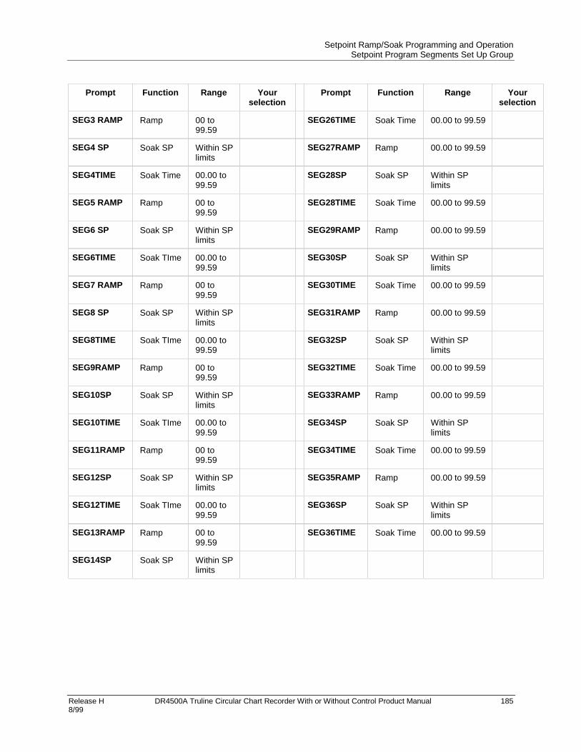
Setpoint Ramp/Soak Programming and OperationSetpoint Program Segments Set Up Group
Release H DR4500A Truline Circular Chart Recorder With or Without Control Product Manual 1858/99
Prompt Function Range Yourselection
Prompt Function Range Yourselection
SEG3 RAMP Ramp 00 to99.59
SEG26TIME Soak Time 00.00 to 99.59
SEG4 SP Soak SP Within SPlimits
SEG27RAMP Ramp 00.00 to 99.59
SEG4TIME Soak Time 00.00 to99.59
SEG28SP Soak SP Within SPlimits
SEG5 RAMP Ramp 00 to99.59
SEG28TIME Soak Time 00.00 to 99.59
SEG6 SP Soak SP Within SPlimits
SEG29RAMP Ramp 00.00 to 99.59
SEG6TIME Soak TIme 00.00 to99.59
SEG30SP Soak SP Within SPlimits
SEG7 RAMP Ramp 00 to99.59
SEG30TIME Soak Time 00.00 to 99.59
SEG8 SP Soak SP Within SPlimits
SEG31RAMP Ramp 00.00 to 99.59
SEG8TIME Soak TIme 00.00 to99.59
SEG32SP Soak SP Within SPlimits
SEG9RAMP Ramp 00 to99.59
SEG32TIME Soak Time 00.00 to 99.59
SEG10SP Soak SP Within SPlimits
SEG33RAMP Ramp 00.00 to 99.59
SEG10TIME Soak TIme 00.00 to99.59
SEG34SP Soak SP Within SPlimits
SEG11RAMP Ramp 00 to99.59
SEG34TIME Soak Time 00.00 to 99.59
SEG12SP Soak SP Within SPlimits
SEG35RAMP Ramp 00.00 to 99.59
SEG12TIME Soak TIme 00.00 to99.59
SEG36SP Soak SP Within SPlimits
SEG13RAMP Ramp 00 to99.59
SEG36TIME Soak Time 00.00 to 99.59
SEG14SP Soak SP Within SPlimits

Setpoint Ramp/Soak Programming and OperationSetpoint Program Event Set Up Group
186 DR4500A Truline Circular Chart Recorder With or Without Control Product Manual Release H 8/99
6.7 Setpoint Program Event Set Up Group
Introduction
Segment events are used to activate relays by means of alarms. There are six alarms and six correspondingrelays. Alarm 1 controls Relay 1, Alarm 2 controls Relay 2, etc. When the setpoint program reaches thesegment, the segment event triggers the alarm which triggers the relay. The relay stays on for the durationof the segment. There are no alarm conditions to be satisfied, that is, when the event goes on the alarmgoes on.
How to trigger a relay with a segment event
1. Program the segment event with the alarm corresponding with the desired relay.
2. Program that alarm as type EVENT. It is not necessary to program any alarm parameters other than thealarm type.
3. Do not program other functions that have higher priority control of the relay. See Table 6-6.
Setpoint Program Event group prompts
Table 6-5 lists all the function prompts in the Setpoint Program Event setup group and their definitions.
Table 6-5 Setpoint Program Event Group Definitions
Lower DisplayPrompt
Upper DisplayRange of Setting or Selection
Parameter Definition
SEGx EV
(x = 1-36)
NONEALARM1, ALARM2, ALARM3,ALARM4, ALARM5, ALARM6
Configured event will be active during the segment. Allothers will be inactive.
Example of how a segment event works
For example, to have Segment 1 energize Relay 1:
• Program SEG1 EV as ALARM1.
• Program A1S1TYPE or A1S2TYPE as EVENT.
• Do not program the Timer function Relay 1; namely, Timer.
For alarm programming information, see section 4.12.

Setpoint Ramp/Soak Programming and OperationSetpoint Program Event Set Up Group
Release H DR4500A Truline Circular Chart Recorder With or Without Control Product Manual 1878/99
To ensure control of relay by segment event
To make sure a segment event operates the associated relay, observe the requirements below.
Table 6-6 Segment Event relay operation requirements
Relay Relay is controlled by (in order of priority) Requirements for operation ofrelay by segment event
1 1. Timer function
2. Alarm 1
• Do not configure Timer.
• Configure Alarm 1 typeEvent.
2 Alarm 2 Configure Alarm 2 type Event.
3 1. Controller 1 output algorithms Relay Simplex,Position Proportional, Relay Duplex,Current/Relay Duplex
2. Alarm 3
• Do not configure Controller#1 with these outputalgorithms.
• Configure Alarm 3 typeEvent.
4 1. Controller 1 output algorithms PositionProportional, Relay Duplex, Current/RelayDuplex
2. Alarm 4
• Do not configure Controller#1 with these outputalgorithms.
• Configure Alarm 4 typeEvent.
5 1. Controller 2 output algorithms Relay Simplex,Position Proportional, Relay Duplex,Current/Relay Duplex
2. Alarm 5
• Do not configure Controller#2 with these outputalgorithms.
• Configure Alarm 5 typeEvent.
6 1. Controller 2 output algorithms PositionProportional, Relay Duplex, Current/RelayDuplex
2. Alarm 6
• Do not configure Controller#2 with these outputalgorithms.
• Configure Alarm 6 typeEvent.

Setpoint Ramp/Soak Programming and OperationSetpoint Program Event Set Up Group
188 DR4500A Truline Circular Chart Recorder With or Without Control Product Manual Release H 8/99
SPP EVNT worksheet
Use this worksheet to make a record of the segment event settings.
Prompt Description Range Your selection
SPP EVNT Access to events N/A N/A
SEG1 EV Event status NONEALARM1ALARM2ALARM3ALARM4ALARM5ALARM6
SEG2 EV Event status Same
SEG3 EV Event status Same
SEG4 EV Event status Same
SEG5 EV Event status Same
SEG6 EV Event status Same
SEG7 EV Event status Same
SEG8 EV Event status Same
SEG9 EV Event status Same
SEG10 EV Event status Same
SEG11 EV Event status Same
SEG12 EV Event status Same
SEG13 EV Event status Same
SEG14 EV Event status Same
SEG15 EV Event status Same
SEG16 EV Event status Same
SEG17 EV Event status Same
SEG18 EV Event status Same
SEG19 EV Event status Same
SEG20 EV Event status Same
SEG21 EV Event status Same
SEG22 EV Event status Same
SEG23 EV Event status Same
SEG24 EV Event status Same
SEG25 EV Event status Same
SEG26 EV Event status Same

Setpoint Ramp/Soak Programming and OperationSetpoint Program Event Set Up Group
Release H DR4500A Truline Circular Chart Recorder With or Without Control Product Manual 1898/99
Prompt Description Range Your selection
SEG27 EV Event status Same
SEG28 EV Event status Same
SEG29 EV Event status Same
SEG30 EV Event status Same
SEG31 EV Event status Same
SEG32 EV Event status Same
SEG33 EV Event status Same
SEG34 EV Event status Same
SEG35 EV Event status Same
SEG36 EV Event status Same

Setpoint Ramp/Soak Programming and OperationRun/Monitor the Program
190 DR4500A Truline Circular Chart Recorder With or Without Control Product Manual Release H 8/99
6.8 Run/Monitor the Program
Introduction
Make sure all the “SP PROG” function prompts under the Set Up group “SP RAMP” have been configuredwith the required data.
• An “H” appears in the upper display indicating that the program is in the HOLD state. If an “H” doesn’tappear, go to the SP Program configuration procedure and enable the program instead of disabling.
ATTENTION
For recorders with two controllers (both enabled), remember that any controller-related valuesdisplayed correspond with the lighted CHN indicator. “1” means that the values apply forController #1 and “2” means that the values apply for Controller #2.
Run/Monitor functions
Table 6-7 lists all the functions required to run and monitor the program.
Table 6-7 Run/Monitor Functions
Function Press Result
Run State RUNHOLD
Initiates the setpoint program.
“H” changes to “R” in the upper display indicating that theprogram is running.PV value and pen trace tracks the ramp soak profile.
Hold State RUNHOLD
Holds the setpoint program.
• An “H” appears in the upper display indicating that theprogram is in the HOLD state.
• The setpoint holds at the current setpoint. Press againto continue to run.
External Hold If Remote Switching (Digital Input Option) is present onyour recorder, contact closure places the recorder in theHOLD state, if the setpoint program is running.
• The “H” in the upper display blinks.
ATTENTION The keyboard takes priority overexternal switch for the RUN/HOLD function.
• Contact reopening runs program.

Setpoint Ramp/Soak Programming and OperationRun/Monitor the Program
Release H DR4500A Truline Circular Chart Recorder With or Without Control Product Manual 1918/99
Function Press Result
Viewing the presentramp or soak segmentnumber and time
LOWRDISP
Until you see:
Upper Display: R and the PV value
Lower Display:
For Ramp segments:
# RA XX.XX
Segment Number (odd only)
Indicates Ramp segment
Ramp Time - Hours:Minutes or Ramp Rate - Degrees/Minute
For Soak segments:
# SK XX.XX
Segment Number (even only)
Indicates Soak segment
Time remaining in segment in Hrs:Minutes including current partially completed minute
Skipping segments LOWRDISP
Until you see:
Upper Display: R and the PV value
Lower Display: #RA XX.XX (Ramp Segment)#SK XX.XX (Soak Segment)
RUNHOLD
To hold the SP Program
• An “H” appears in the upper display indicating that theprogram is in the HOLD state.
or To select new segment
RUNHOLD
or
LOWRDISP
To begin running at new segment
To retain the old segment
Viewing the number ofcycles left in theprogram
LOWERDISP
Until you see:
Upper Display: R and the PV value
Lower Display: RECYC XXRemaining cycles 0 to 99This number includes the currentpartially completed cycle.
End Program When the final segment is completed, the “R” in the upperdisplay either changes to “H” if configured for HOLD state,or disappears if configured for DISABL of setpointprogramming.
• The recorder operates at the last setpoint in theprogram in automatic or will be in manual mode at thefailsafe output.

Setpoint Ramp/Soak Programming and OperationRun/Monitor the Program
192 DR4500A Truline Circular Chart Recorder With or Without Control Product Manual Release H 8/99

Release H DR4500A Truline Circular Chart Recorder With or Without Control Product Manual 1938/99
7. Input Calibration
7.1 Overview
SHOCK HAZARD
INPUT CALIBRATION MAY REQUIRE ACCESS TO HAZARDOUS LIVE CIRCUITS, ANDSHOULD ONLY BE PERFORMED BY QUALIFIED SERVICE PERSONNEL. MORE THANONE SWITCH MAY BE REQUIRED TO DE-ENERGIZE UNIT BEFORE CALIBRATION.
Introduction
This section describes the field calibration procedures for inputs 1, 2, 3, and 4. All DR4500A recorders arefactory calibrated prior to shipment. It should not, therefore, be necessary to recalibrate the recorder when itis initially installed. However, you must recalibrate the input if any one of the conditions summarizedbelow applies:
• The thermocouple or RTD input must meet published* accuracy rates. Note that the factory calibrationat reference is ±1.2°F plus ±10 microvolts for thermocouples or ±0.3 ohms for RTDs.
* Specifications 44-45-03-14
• You are using a 0–10 Vdc input. Recalibration is necessary because the resistor network used for thisinput has a tolerance of ±1.0%.
• You have cause to believe that the recorder is out of calibration.
• You must perform regularly scheduled or periodic recalibration based on your own needs.
• You have performed specific servicing activities such as replacement of an input PCB.
ATTENTION
Replacing a main PCB does not normally require recalibration since a new main PCB isalready factory calibrated, whereas an input PCB is not.
• You have changed the input type through configuration which results in the loss of the previous fieldcalibration, but restores factory calibration. See subsection 7.2 Restoring Factory Calibration paragraphthat follows.
What’s in this section?
This section contains the following topics:
Topic See Page
7.1 Overview 193
7.2 Restoring Factory Calibration 194
7.3 Minimum and Maximum Range Values 196
7.4 Preliminary Information 197
7.5 Calibration Set Up and Wiring for PV Inputs 199
7.6 Calibration Procedure 208
7.7 Printing Characteristics Adjustments 211

Input CalibrationRestoring Factory Calibration
194 DR4500A Truline Circular Chart Recorder With or Without Control Product Manual Release H 8/99
7.2 Restoring Factory Calibration
How to restore it
The factory calibration constants for all the input actuation types that can be used with the DR4500Arecorder are stored in its nonvolatile memory. Thus, you can quickly restore the “Factory Calibration” for agiven input actuation type by simply configuring the actuation type through the IN1 TYPE (or IN2 TYPE,IN3 TYPE, IN4 TYPE) prompt to another type and then changing it back to the original type. See Table7-1 for the procedure.
ATTENTION
This procedure applies only for factory-installed inputs. Any input that was field-installed mustbe field calibrated.
Procedure
Table 7-1 lists the procedure for restoring factory calibration.
Table 7-1 Restoring Factory Calibration
Step Operation Press Action/Result
1 Enter Input Setup Group SETUP
Until you see:
Upper Display: SET UP
Lower Display: INPUT n n = 1, 2, 3, or 4
2 Change input type FUNC Until you see:
Upper Display: Note the input type in the upperdisplay. Make sure that theselection matches the type ofsensor that is connected to theinput in your application. Write itdown, if necessary.
Lower Display: INn TYPE n = 1, 2, 3, or 4
or Until you see:
Upper Display: 0-10V
Lower Display: INn TYPE
ATTENTION If you are already using a 0-10Vinput, change to a 0-5V input type.
FUNC Until the upper display rolls through the input types andreturns to
Upper Display: 0-10V
Lower Display: INn TYPE

Input CalibrationRestoring Factory Calibration
Release H DR4500A Truline Circular Chart Recorder With or Without Control Product Manual 1958/99
Step Operation Press Action/Result
or Until you change the input selection in the upperdisplay back to the proper selection. You will see:
Upper Display: Original input selection thatmatches your type of sensor.
Lower Display: INn TYPE
3 Return to normaloperating mode
LOWRDISP
To return to Normal operating mode.
The factory calibration will be restored. If the problem isnot corrected, contact the Honeywell TechnicalAssistance Center.
1-800-423-9883 USA and Canada
CAUTION
A restored factory calibration overwrites any previous field calibration done for the input. Besure to protect any field calibration from accidental overwrites by configuring the appropriate“LOCKOUT” selection after calibration. See the Section 3 - Configuration for specificinstructions to set the lockout.

Input CalibrationMinimum and Maximum Range Values
196 DR4500A Truline Circular Chart Recorder With or Without Control Product Manual Release H 8/99
7.3 Minimum and Maximum Range Values
Select the range values
You should calibrate the recorder for the minimum (0%) and maximum (100%) range values of yourparticular sensor.
• If your recorder has two or more inputs, calibrate each input separately. Select the voltage or resistanceequivalent for 0% and 100% range values from Table 7-2, use these values when calibrating yourrecorder.
Table 7-2 Voltage and Resistance Equivalents for 0% and 100% Range Values
Sensor Type PV Input Range Range Values*
Thermocouples °F °C 0% 68°F/20°C 100%
B 105 to 3300 41 to 1816 0 mV 0.003 mV 13.763 mVE –454 to 1832 –270 to 1000 –9.835 mV 1.192 mV 76.358 mV
E (low) –200 to 1100 –129 to 593 –6.471 mV 44.547 mVJ 0 to 1600 –18 to 871 –0.885 mV 1.019 mV 50.059 mV
J (low) 20 to 770 –7 to 410 –0.334 mV 22.397 mVK –320 to 2500 –196 to 1371 –5.822 mV 0.798 mV 54.845 mV
K (low) –20 to 1000 –29 to 538 –1.114 mV 22.251 mVNiNiMoly 32 to 2500 0 to 1371 –0.001 mV 1.458 mV 71.330 mV
NIC Nicrosil Nisil 0 to 2372 –17.8 to 1300 –0.461 mV 0.525 mV 47.502 mVR 0 to 3100 –18 to 1704 –0.089 mV 0.111 mV 20.275 mVS 0 to 3100 –18 to 1704 –0.092 mV 0.113 mV 17.993 mVT –300 to 700 –184 to 371 –5.341 mV 0.789 mV 19.095 mV
T (low) –200 to 600 –129 to 316 –4.149 mV 15.769 mVW5W26 0 to 4200 –18 to 2315 –0.234 mV 0.062 mV 37.066 mV
W5W26 (low) 0 to 2240 –18 to 1227 –0.234 mV 22.277 mVRTD***100
1005+200200500
–300 to 900–130 to 392
32 to 75232 to 392
–300 to 900
–184 to 482–90 to 200
0 to 4000 to 200
–184 to 482
25.1864.30200200
125.90
274.96175.84498.10353.74
1374.80Milliamps 4 to 20 mA 4 mA 20 mA
0 to 10 mV 0 mV 10 mVMillivolts
10 to 50 mV 10 mV 50 mV0 to 5 Volts 0 Volts 5 Volts
Volts0 to 10 Volts** 0 Vols 10 Volts
Radiamatic (RH) 1400 to 3400 760 to 1871 0.99 mV 57.12 mV
*Range values for thermocouples are based on a cold junction temperature of 32°F (0°C). These values must beadjusted for the actual cold junction temperature when using the ambient temperature method for calibratingthermocouple inputs.
**Resistor network 30755232-002 must be installed in inputs #1, #2, #3, and #4 when using this range, see set updiagram for details.
***IEC = .00385—100IEC = .003902—200

Input CalibrationPreliminary Information
Release H DR4500A Truline Circular Chart Recorder With or Without Control Product Manual 1978/99
7.4 Preliminary Information
Disconnect the field wiring
Depending on which input (#1, #2, #3, or #4) you are going to calibrate, tag and disconnect any field wiringconnected to the input terminals on the input boards inside the recorder. Reference Figure 7-1 and followthe procedure in Table 7-3.
Table 7-3 Disconnect the Field Wiring
Step Action
1 Remove the operating power from the recorder.
2 Open the door on the recorder.
3 Loosen the phillips screw on the right side of the chart plate, and open the chart plate.
4 Depending on the input (1, 2, 3, or 4) you are going to calibrate, remove the wired plug fromthe input connector (J2) on the applicable circuit board. See Figure 7-1 for the location of thecircuit boards and input connectors.
5 Tag and disconnect the field wiring installed in the applicable input connector plug.
#3#4 #2 #1
Mother board for options
21442
Main board
Alarm output digital input board (optional)
J2 on input #1 board
J2 on input #2 board (optional)
J2 on input #3 board (optional)
J2 on input #4 board (optional)
Figure 7-1 Location of the Input Connections on the Input Boards

Input CalibrationPreliminary Information
198 DR4500A Truline Circular Chart Recorder With or Without Control Product Manual Release H 8/99
Equipment needed
Table 7-4 lists the equipment required to calibrate the specific types of inputs listed in the table. You willneed a medium size bladed screwdriver for general use and a small size bladed screwdriver for use with thescrews on the connector plugs.
Table 7-4 Equipment Needed
Type of Input Equipment Needed
Thermocouple Inputs(Ice Bath)
• A calibrating device with ±0.02% accuracy for use as asignal source such as a millivolt source.
• Thermocouple extension wire that corresponds with thetype of thermocouple that will be used with the recorderinput.
• Two insulated copper leads for connecting thethermocouple extension wire from the ice baths to theprecision calibrator.
• Two containers of crushed ice.
Thermocouple Inputs(Ambient Temperature)
• A calibrating device with ±0.02% accuracy for use as asignal source such as a millivolt source.
• Two insulated copper leads for connecting the calibrator tothe controller.
Thermocouple Inputs(Compensated Calibrator)
• A calibrating device with temperature compensation and±0.02% accuracy for use as a signal source.
• Thermocouple extension wire that corresponds with thetype of thermocouple that will be used with the recorderinput.
RTD (Resistance ThermometerDevice)
• A resistance decade box, with ±0.02% accuracy, capableof providing stepped resistance values over a minimumrange of 0 to 1400 Ohms with a resolution of 0.01 ohm.
• Three insulated copper leads for connecting the decadebox to the controller.
Radiamatic, Milliampere, Millivolt, andVolts Inputs
• A calibrating device with ±0.02% accuracy for use as asignal source.
• Two insulated copper leads for connecting the calibrator tothe controller.

Input CalibrationCalibration Set Up and Wiring for PV Inputs
Release H DR4500A Truline Circular Chart Recorder With or Without Control Product Manual 1998/99
7.5 Calibration Set Up and Wiring for PV Inputs
Jumper positions
Before starting the calibration activity, check that the jumper plugs on the applicable input circuit board areinstalled in the proper jumper position (in W1/MA and W3) for the particular sensor being used (refer tothe wiring connection drawings in this section for each individual setting).
Refer to Figure 7-2 for the location of jumper positions W1/MA and W3 on these circuit boards, and thestatus of these jumpers for each type of input sensor.
Main board
Input board
W1
MA
MA
Position MA Position W1
Status of jumper plugs
1. Install W1/MA plug in position W1 for thermocouple, RTD, Radiamatic, mV, 0-5 Vdc, 0-10 Vdc inputs.
2. Install W1/MA plug in position MA for 4-20 mA inputs.
21443
RT
DW
3
Position T/C MA Linear
Position RTD
3. Install plug in W3 according to your input type.
T/C
Figure 7-2 Location of Jumper Positions W1/MA and W3 on the Input Boards

Input CalibrationCalibration Set Up and Wiring for PV Inputs
200 DR4500A Truline Circular Chart Recorder With or Without Control Product Manual Release H 8/99
Thermocouple input calibration methods
You can calibrate for a thermocouple input using one of three methods:
• using an ice bath,
• using a compensated calibrator, or
• by measuring the ambient temperature at the input terminals and subtracting the voltage contributionof the input terminal junction.
General set up procedure
Table 7-5 lists the general set up procedure for all methods of calibration. Do this procedure and then referto the set up procedure and diagram for your specific input.
Table 7-5 General Set Up Procedure
Step Action
1 Set up and connect the calibrator to the input plug for the applicable input circuit board in yourrecorder according to the particular input sensor being used. Refer to the following figures forcorresponding set-up diagrams:
• Figure 7-3 Thermocouple inputs using an ice bath
• Figure 7-4 Thermocouple inputs using a compensated calibrator
• Figure 7-5 Thermocouple inputs using the ambient temperature method
• Figure 7-6 RTD (Resistance Thermometer Device) inputs
• Figure 7-7 Radiamatic, mV and Volts (except 0–10 Volts) inputs
• Figure 7-8 0-10 Volts input
• Figure 7-9 4–20 mA inputs
2 Route leads (for example: copper leads or thermocouple extension wires) through a conduithole in the recorder case so that you will be able to close the chart plate.
3 Close the chart plate after you have completed the applicable calibration set up.

Input CalibrationCalibration Set Up and Wiring for PV Inputs
Release H DR4500A Truline Circular Chart Recorder With or Without Control Product Manual 2018/99
Thermocouple inputs using an ice bath
Refer to Figure 7-3 and wire the recorder according to the procedure given in Table 7-6.
Table 7-6 Set Up Wiring Procedure for Thermocouple Inputs Using an Ice Bath
Step Action
1 Connect the copper leads to the calibration source (see Figure 7-3).
2 Connect a length of thermocouple extension wire to the end of each copper lead and insert thejunction points into the ice bath.
3 Connect the other end of the thermocouple extension wires to the clamp type terminals in theplug for the applicable input connector (J2).
4 Reinstall the plug into the input connector (J2) on the applicable circuit board for Input 1, Input2, Input 3, or Input 4.
#3#4 #2 #1
21444
Connector plug J2 for inputs #1, #2, #3 & #4
MA W1
Be sure W1/MA jumper is in position W1 on the input board.
Containers of crushed ice
_+
Copper wires
Calibration source
+
_
Thermocouple extension wires T/C
RTD
Be sure W3 jumper is in position T/C on the input board.
Figure 7-3 Calibration Set Up Diagram for Thermocouple Inputs Using an Ice Bath

Input CalibrationCalibration Set Up and Wiring for PV Inputs
202 DR4500A Truline Circular Chart Recorder With or Without Control Product Manual Release H 8/99
Thermocouple inputs using a compensated calibrator method
Refer to Figure 7-4 and wire the recorder according to the procedure given in Table 7-7.
Table 7-7 Set Up Wiring Procedure for Thermocouple Inputs Using a CompensatedCalibrator Method
Step Action
1 Connect the thermocouple extension wire to the Precision Compensated Calibrator (seeFigure 7-4).
2 Connect the other end of the thermocouple extension wires to the clamp type terminals in theplug for the applicable input connector (J2).
3 Reinstall the plug into the input connector (J2) on the applicable circuit board for Input 1, Input2, Input 3, or Input 4.
#3#4 #2 #1
21445
Connector plug J2 for inputs #1, #2, #3 & #4
MA
W1
Be sure W1/MA jumper is in position W1 on the input board.
+
_
Thermocouple extension wires _
+
Compensated Calibrator
T/C
RTD
Be sure W3 jumper is in position T/C on the input board.
Figure 7-4 Calibration Set Up Diagram for Thermocouple Inputs Using a CompensatedCalibrator Method

Input CalibrationCalibration Set Up and Wiring for PV Inputs
Release H DR4500A Truline Circular Chart Recorder With or Without Control Product Manual 2038/99
Thermocouple inputs using the ambient temperature method
Refer to Figure 7-5 and wire the recorder according to the procedure given in Table 7-8.
Table 7-8 Set Up Wiring Procedure for Thermocouple Inputs Using the AmbientTemperature Method
Step Action
1 Connect the copper wire to the Precision Millivolt Source (see Figure 7-5).
2 Connect the other end of the copper wire to the clamp type terminals in the plug for theapplicable input connector (J2).
3 Reinstall the plug into the input connector (J2) on the applicable circuit board for input 1, input2, input 3, or input 4.
#3#4 #2 #1
21446
Connector plug J2 for inputs #1, #2, #3 and #4
MA W1
Be sure W1/MA jumper is in position W1 on the input board.
Copper wires
+
_
_+
Calibration source
Adjust calibration voltages to compensate for measured ambient temperature
Ambient temperature method T/C
RTD
Be sure W3 jumper is in position T/C on the input board.
Figure 7-5 Calibration Set Up Diagram for Thermocouple Inputs using the AmbientTemperature Method

Input CalibrationCalibration Set Up and Wiring for PV Inputs
204 DR4500A Truline Circular Chart Recorder With or Without Control Product Manual Release H 8/99
RTD (Resistance Thermometer Device) inputs
Refer to Figure 7-6 and wire the recorder according to the procedure given in Table 7-9.
Table 7-9 Set Up Wiring Procedure for RTD Inputs
Step Action
1 Connect the copper wire to the calibration source (see Figure 7-6).
2 Connect the other end of the copper wire to the clamp type terminals in the plug for theapplicable input connector (J2).
3 Reinstall the plug into the input connector (J2) on the applicable circuit board for input 1, input2, input 3, or input 4.
#3#4 #2 #1
21447
Copper wires
Decade box
Plug J2
MA
W1
Be sure W1/MA jumper is in position W1 on the input board.
+
_
T/C
RTD
Be sure W3 jumper is in position RTD on the input board.
Figure 7-6 Calibration Set Up Diagram for RTD Inputs

Input CalibrationCalibration Set Up and Wiring for PV Inputs
Release H DR4500A Truline Circular Chart Recorder With or Without Control Product Manual 2058/99
Radiamatic, millivolts, and volts inputs (except 0–10 Volts)
Refer to Figure 7-7 and wire the recorder according to the procedure given in Table 7-10.
Table 7-10 Set Up Wiring Procedure for Radiamatic, Millivolts, and Volts Inputs(except 0-10 Volts)
Step Action
1 Connect the copper wire to the calibration source (see Figure 7-7).
2 Connect the other end of the copper wire to the clamp type terminals in the plug for theapplicable input connector (J2).
3 Reinstall the plug into the input connector (J2) on the applicable circuit board for input 1, input2, input 3, or input 4.
#3#4 #2 #1
21448
+
_
Copper wires
_+
Calibration source
Plug J2
MA
W1
Be sure W1/MA jumper is in position W1 on the input board.
T/C
RTD
Be sure W3 jumper is in the Linear position on the input board.
Figure 7-7 Calibration Set Up Diagram for Radiamatic, Millivolts, and Volts Inputs(except 0-10 Volts)

Input CalibrationCalibration Set Up and Wiring for PV Inputs
206 DR4500A Truline Circular Chart Recorder With or Without Control Product Manual Release H 8/99
0–10 Volt inputs
Refer to Figure 7-8 and wire the recorder according to the procedure given in Table 7-11.
Table 7-11 Set Up Wiring Procedure for 0–10 Volt Inputs
Step Action
1 Connect the copper wire to the calibration source (see Figure 7-8).
2 Connect the other end of the copper wire to the clamp type terminals in the plug for theapplicable input connector (J2).
3 Reinstall the plug into the input connector (J2) on the applicable circuit board for input 1, input2, input 3, or input 4.
#3#4 #2 #1
21449
MA W1
Be sure W1/MA jumper is in position W1 on the input board.
_+
Copper wires
Calibration source
Plug J2
+
_
*
* Resistor assembly (part no. 30755232-002) is furnished with the recorder.
T/C
RTD
Be sure W3 jumper is in the Linear position on the input board.
Figure 7-8 Calibration Set Up Diagram for 0–10 Volt Inputs

Input CalibrationCalibration Set Up and Wiring for PV Inputs
Release H DR4500A Truline Circular Chart Recorder With or Without Control Product Manual 2078/99
4–20 mA inputs
Refer to Figure 7-9 and wire the recorder according to the procedure given in Table 7-12.
Table 7-12 Set Up Wiring Procedure for 4–20 mA Inputs
Step Action
1 Connect the copper wire to the calibration source (see Figure 7-9).
2 Connect the other end of the copper wire to the clamp type terminals in the plug for theapplicable input connector (J2).
3 Reinstall the plug into the input connector (J2) on the applicable circuit board for input 1, input2, input 3, or input 4.
#3#4 #2 #1
21450
MA
W1
Be sure W1/MA jumper is in position MA on the input board;
this connects 250Ω resistor (internal on PCB) across inputs terminals.
_+
Copper wires
Calibration source
+
_
Plug J2
4-20 mA
T/C
RTD
Be sure W3 jumper is in theLinear position on the Input board.
Figure 7-9 Calibration Set Up Diagram for 4–20 mA Inputs

Input CalibrationCalibration Procedure
208 DR4500A Truline Circular Chart Recorder With or Without Control Product Manual Release H 8/99
7.6 Calibration Procedure
Introduction
Apply power and allow the recorder to warm up for one hour before you calibrate.
• Please read “Set Up Wiring” before beginning the procedure.
• Make sure “LOCKOUT” is set to “NONE.” (see Section 3 – Configuration).
• The calibration procedure for inputs #1, #2, #3, and #4 are identical. The displays indicate the inputnumber.
CAUTION
For milliampere inputs, be sure the current source is at zero before switching on the calibrator.Do not switch the calibrator on/off while it is connected to the recorder’s input.
ATTENTION
For linear inputs, avoid step changes in input signal. Vary calibration source signal smoothlyfrom initial value to final 100% value.
Calibration procedure sequence
The calibration procedure sequence for all inputs is listed in Table 7-13.
Table 7-13 Calibration Procedure Sequence
Step Operation Press Action/Result
1 Enter Calibration Mode SETUP
Until you see:
Upper Display: CALIB
Lower Display: INPUT n n = 1, 2, 3, or 4
FUNC You will see:
Upper Display: DISABL
Lower Display: CAL INn n = 1, 2, 3, or 4
The calibration sequence is enabled and you will see:
Upper Display: BEGIN
Lower Display: CAL INn

Input CalibrationCalibration Procedure
Release H DR4500A Truline Circular Chart Recorder With or Without Control Product Manual 2098/99
Step Operation Press Action/Result
2 Calibrate 0% FUNC You will see:
Upper Display: APPLY
Lower Display: INn ZERO n = 1, 2, 3, or 4
• Adjust your calibration device to an output signalequal to the 0% range value for your particular inputsensor, see Table 7-2 for Voltage or Resistanceequivalents.
• Wait 30 seconds, then go to the next step 3.
Using AmbientTemperature Method
ATTENTION If you are using the AmbientTemperature method to calibrate a thermocouple input,be sure to measure the temperature at the inputterminals and subtract the equivalent millivolt value (foryour particular thermocouple) from the 0% value justprior to doing calibration.
For example, for a Type J Thermocouple and inputtemperature of 68°F:
From –0.885 mV (Type J @ 0°F)Subtract –1.019 mV (Type J @ 68°F)To yield –1.904 mV (calibrator output
for INn ZERO)
3 Calibrate 100% FUNC You will see:
Upper Display: APPLY
Lower Display: INn SPAN n = 1, 2, 3, or 4
Adjust your calibration device to an output signal equalto the 100% range value for your particular inputsensor, see Table 7-2 for voltage or resistanceequivalents, wait 30 seconds, and
If … Then …
you are calibrating athermocouple input
Go tostep 4
you are calibrating other than athermocouple input
Go tostep 5
Using AmbientTemperature Method
ATTENTION If you are using the AmbientTemperature method to calibrate a thermocouple input,be sure to measure the temperature at the inputterminals and subtract the equivalent millivolt value (foryour particular thermocouple) from the 100% value.
For example, for a Type J Thermocouple and inputtemperature of 68°F:
From 50.059 mV (Type J @ 1600°F)Subtract –1.019 mV (Type J @ 68°F)To yield 49.040 mV (calibrator output
for INn SPAN)

Input CalibrationCalibration Procedure
210 DR4500A Truline Circular Chart Recorder With or Without Control Product Manual Release H 8/99
Step Operation Press Action/Result
4 Check the Cold JunctionTemperature
WARNING Theaccuracy of the recorderis directly affected by theaccuracy of this value.Change this value only ifthe zero and spancalibration procedures didnot bring the controllerwithin the specifiedaccuracy requirements.
FUNC The calculations for zero and span are now stored andyou will see:
Upper Display: The cold junction temperature atthe rear terminals
Lower Display: C-J TEMP
• The value in the upper display is in the tenths of adegree. It is the current reading of the temperatureas measured at the thermocouple terminals(that is, at J2) and recognized by the recorder.
• When using the Ice Bath method, this value shouldbe the terminal ambient temperature.
− You can change this value, if it is in error, using the RU NH\
5 Exit the Calibration Mode FUNC The recorder stores the calibration constants and exitcalibration mode.

Input CalibrationPrinting Characteristics Adjustments
Release H DR4500A Truline Circular Chart Recorder With or Without Control Product Manual 2118/99
7.7 Printing Characteristics Adjustments
Printing characteristics adjustments
Normally there is no need to adjust the printing characteristics as part of an input or output calibrationprocedure. However, if the chart printing appears to be faded, you can use the procedure in Section 4 -Configuration Definitions, Table 4-19, to make slight adjustments in the print contrast.
ATTENTION
To access Set Up group prompt “ADJUST”, the Set Up group prompt “LOCKOUT” must be setto “NONE”. If the group prompt “LOCKOUT” has been configured for “CALIB”, “+VIEW”, or“MAX” selection, you will not be able to access the Printing Characteristics Group prompt.Refer to Section 3 - Configuration for details.

Input CalibrationPrinting Characteristics Adjustments
212 DR4500A Truline Circular Chart Recorder With or Without Control Product Manual Release H 8/99

Release H DR4500A Truline Circular Chart Recorder With or Without Control Product Manual 2138/99
8. Output Calibration
8.1 Overview
SHOCK HAZARD
OUTPUT CALIBRATION MAY REQUIRE ACCESS TO HAZARDOUS LIVE CIRCUITS, ANDSHOULD ONLY BE PERFORMED BY QUALIFIED SERVICE PERSONNEL. MORE THANONE SWITCH MAY BE REQUIRED TO DE-ENERGIZE UNIT BEFORE CALIBRATION.
Introduction
This section describes the field calibration procedures for the following types of outputs:
• Current Output
• Position Proportional Output
• Auxiliary Output
ATTENTION
Calibration for Control Outputs #1 and #2 is identical except for the particular printed circuitboard involved.
What’s in this section
This section contains the following topics:
Topic See Page
8.1 Overview 213
8.2 Current Proportional Output CalibrationIntroductionEquipment neededCalibrator connections&DOLEUDWLRQProcedure
214214214214215
8.3 Position Proportional and Three Position Step Output CalibrationPosition proportional controlEquipment neededConnectionsAuto mode vs manual modeDisplayed values&DOLEUDWLRQProcedure
216216216216216216216
8.4 Auxiliary Output CalibrationIntroductionEquipment neededCalibrator connections&DOLEUDWLRQProcedure
219219219219220

Output CalibrationCurrent Proportional Output Calibration
214 DR4500A Truline Circular Chart Recorder With or Without Control Product Manual Release H 8/99
8.2 Current Proportional Output Calibration
Introduction
Calibrate the recorder so that the output provides the proper amount of current over the desired range.
• The recorder can provide an output current range of from 2 to 21 milliamperes and can be calibrated at 4mA for 0% of output and 20 mA for 100% of output or any other values between 2 and 21 mA.
Equipment needed
You will need a standard shop type milliammeter, with whatever accuracy is required, capable ofmeasuring 0 to 20 milliamps.
Calibrator connections
Refer to Figure 8-1 and wire the recorder according to the procedure given in Table 8-1.
Table 8-1 Set Up Wiring Procedure Current Proportional Output
Step Action
1 With the power off, door open, and the chart plate swung out; tag and disconnect field wiringfrom the plug in connector J1 on the appropriate control output PCB (see Figure 8-1).
2 Observing polarity, connect a milliammeter’s leads to the plug for connector J1.
3 Close the chart plate: apply power and allow the recorder to warm up 15 minutes before youcalibrate.
21451
Milliammeter
Plug J1 (current output)
+
-
Control output #1 PCB
#3#4 #2 #1
Control output #2 PCB
Figure 8-1 Test Equipment Connections for Calibrating Current Proportional Output

Output CalibrationCurrent Proportional Output Calibration
Release H DR4500A Truline Circular Chart Recorder With or Without Control Product Manual 2158/99
Procedure
The procedure for calibrating the Current Proportional Output is listed in Table 8-2. Make sure“LOCKOUT” in the Set Up group is set to “NONE.” See Section 3 – Configuration. Also, “CONTROL1/2” must be enabled in the Options group and “OUT ALG” must be set to “CURRNT” in the Controlgroup.
Table 8-2 Current Proportional Output Calibration Procedure
Step Operation Press Action/Result
1 Enter Calibration Mode SETUP
Until you see:
Upper Display: CALIB
Lower Display: CURRENT
2 Calibrate 0% FUNC You will see:
Upper Display: (a value) (approximately 380)
Lower Display: ZERO VAL
or Until the desired 0% output is read on the milliammeter.Use the values shown below depending on the actionof your recorder.
4 mA For 4 to 20 mA Direct Action20 mA For 4 to 20 mA Reverse Action
3 Calibrate 100% FUNC Stores the 0% value and you will see:
Upper Display: (a value) (approximately 1890)
Lower Display: SPAN VAL
or Until the desired 100% output is read on themilliammeter. Use the values shown below dependingon the action of your recorder.
20 mA For 4 to 20 mA Direct Action4 mA For 4 to 20 mA Reverse Action
4 Exit the Calibration Mode FUNC The recorder stores the span value.
LOWRDISP
or
SETUP
To exit the calibration mode.

Output CalibrationPosition Proportional and Three Position Step Output Calibration
216 DR4500A Truline Circular Chart Recorder With or Without Control Product Manual Release H 8/99
8.3 Position Proportional and Three Position Step Output Calibration
Position proportional control
When the DR4500A Recorder has a position proportional control output, calibrate the recorder so that theincrease and decrease relays operate properly with respect to the position of the external feedbackslidewire.
3 Position Step control
This model only requires that the “Motor Time” be entered as shown in the calibration procedure. FULLCALIBRATION IS NOT REQUIRED.
Equipment needed
None
Connections
Apply power and allow the recorder to warm up 15 minutes before you calibrate.
Leave all field wiring connected to the plugs in connectors J2 and J5 on the appropriate control outputprinted circuit board.
Auto mode vs manual mode
There are two ways in which to calibrate Position Proportional control:AUTO mode or MANUAL mode.
Rules for auto mode vs manual mode
The auto-mode selection must be done at least once before the manual mode will operate properly. Failureto use the auto-mode procedure will prevent the recorder from going into automatic control mode.
Displayed values
During the auto-mode calibration procedure, the values being displayed are used only to indicate if themotor is still traveling.
To view the actual calibration value, use the manual mode after the auto-mode is completed. These valuescan be changed for purposes of tweaking the calibration.
Procedure
The procedure for calibrating the position proportional output and 3 Position Step control output is listed inTable 8-3.
• Make sure “LOCKOUT” in the Set Up group is set to “NONE.” See Section 3 – Configuration. Also,“CONTROL 1/2” must be enabled in the Options group.
• For “Three Position Step Control Output models”, do steps 1 and 2 only. Make sure “CONT ALG” =“3P STEP” in the Control Set Up group.
• For “Position Proportional Output”, follow the entire calibration procedure. Make sure “CONT ALG”= “PID A” and “OUT ALG” = “POSITN” in the Control 1 Set Up group.

Output CalibrationPosition Proportional and Three Position Step Output Calibration
Release H DR4500A Truline Circular Chart Recorder With or Without Control Product Manual 2178/99
Table 8-3 Position Proportional and 3 Position Step Output Calibration Procedure
Step Operation Press Action/Result
1 Enter Calibration Mode SETUP
Until you see:
Upper Display: CALIBLower Display: POS PROP
2 FUNC Until you see:
Upper Display: (a value)Lower Display: MTR TIME
Set Motor Traverse Time
NOTE: This is the time ittakes the motor to travelfrom 0 to 100%.
or Until the proper motor stroke time is reached (see themotor specs or measure the time).
• Range of setting = 5 to 255 Seconds
3 Select Automatic orManual Calibration
FUNC Until you see:
Upper Display: DISABLLower Display: POS PROP
• You can calibrate the control output manually or letthe recorder calibrate the control outputautomatically.
• In the “Automatic Calibration Mode” (DO AUTO), thecontrol relays automatically move the motor in theproper direction.
• If desired, however, the motor may be manuallypositioned to 0% and 100% positions.Disconnect the relay wires. “DO MAN”.
• In the “Manual Calibration Mode” (DO MAN) themotor does not move. Instead, the existing 0% and100% values may be changed with the or keys.
or Select automatic or manual calibration.
Upper Display: DO AUTO or DO MANLower Display: POS PROP
• If you select DO AUTO, go to step 4.
• If you select DO MAN, go to step 6.
ATTENTION When calibration is terminated, thisselection reverts to DISABL.
4 DO AUTOSet 0% value
FUNC The decrement relay is turned on to move the motor to0% position.
Upper Display: (counts of feedback slidewire)(0 to 2047)
Lower Display: ZERO VAL
• When the motor stops, the display should stopcounting; go to the next step.

Output CalibrationPosition Proportional and Three Position Step Output Calibration
218 DR4500A Truline Circular Chart Recorder With or Without Control Product Manual Release H 8/99
Step Operation Press Action/Result
5 Set 100% value FUNC The increment relay is turned on to move the motor to100% position.
Upper Display: (counts of feedback slidewire)(0 to 2047)
Lower Display: SPAN VAL
• When the motor stops, the display should stopcounting, then, go on to step 8.
6 DO MANSet 0% value
FUNC You will see:
Upper Display: (existing zero calibration valuein counts) (approximately 100)
Lower Display: ZERO VAL
or Until the desired zero value is reached in the upperdisplay.
Upper Display: (desired zero value)Lower Display: ZERO VAL
7 Set 100% value FUNC The recorder stores the 0% value and you will see:
Upper Display: (existing span calibration valuein counts) (approximately 1500)
Lower Display: SPAN VAL
or Until the desired span value is reached in the upperdisplay.
Upper Display: (desired span value)Lower Display: SPAN VAL
For manual calibration, the motor does not move fromits position prior to the start of position proportionalcalibration.
8 Exit the Calibration Mode FUNC The recorder stores the 100% value.
LOWRDISP
or
SETUP
To exit the calibration mode.

Output CalibrationAuxiliary Output Calibration
Release H DR4500A Truline Circular Chart Recorder With or Without Control Product Manual 2198/99
8.4 Auxiliary Output Calibration
Introduction
Calibrate the recorder so that the auxiliary output provides the proper amount of current over the desiredrange.
• The recorder can provide an auxiliary output current range of from 2 to 21 milliamperes and can becalibrated at 4 mA for 0% of output and 20 mA for 100% of output or any other values between 2 and 21mA.
Equipment needed
You will need a standard shop type milliammeter, with whatever accuracy is required, capable ofmeasuring 0 to 20 milliamps.
Calibrator connections
Refer to Figure 8-2 and wire the recorder according to the procedure given in Table 8-4.
Table 8-4 Set Up Wiring Procedure Auxiliary Output
Step Action
1 With the power off, door open, and the chart plate swung out; tag and disconnect field wiringfrom the plug in connector J2 on the auxiliary output PCB (see Figure 8-2).
2 Observing polarity, connect a milliammeter’s leads to the plug for connector J2.
3 Close the chart plate; apply power and allow the recorder to warm up 15 minutes before youcalibrate.
22842
Milliammeter
Plug J2 (auxiliary output)
+
-
Control output #1 PCB
#3#4 #2 #1Control output #2 PCB
Auxiliary output PCB
Figure 8-2 Test Equipment Connections for Calibrating Auxiliary Output

Output CalibrationAuxiliary Output Calibration
220 DR4500A Truline Circular Chart Recorder With or Without Control Product Manual Release H 8/99
Procedure
The procedure for calibrating the Auxiliary Output is listed in Table 8-5. Make sure “LOCKOUT” in theSet Up group is set to “NONE.” See Section 3 – Configuration. Also, “AUX OUT” must NOT be disabledin the Options Set Up group.
Table 8-5 Auxiliary Output Calibration Procedure
Step Operation Press Action/Result
1 Enter Calibration Mode SETUP
Until you see:
Upper Display: CALIB
Lower Display: AUX OUT
2 Calibrate 0% FUNC You will see:
Upper Display: (a value)
Lower Display: ZERO VAL
or Until the desired 0% (4 mA) output is read on themilliammeter.
3 Calibrate 100% FUNC Stores the 0% value and you will see:
Upper Display: (a value)
Lower Display: SPAN VAL
or Until the desired 100% (20 mA) output is read on themilliammeter.
4 Exit the Calibration Mode FUNC The recorder stores the span value.
LOWRDISP
or
SETUP
To exit the calibration mode.

Release H DR4500A Truline Circular Chart Recorder With or Without Control Product Manual 2218/99
9. Troubleshooting / Service
9.1 Overview
SHOCK HAZARD
TROUBLESHOOTING MAY REQUIRE ACCESS TO HAZARDOUS LIVE CIRCUITS, ANDSHOULD ONLY BE PERFORMED BY QUALIFIED SERVICE PERSONNEL. MORE THANONE SWITCH MAY BE REQUIRED TO DE-ENERGIZE UNIT BEFORE SERVICING.
Introduction
This section explains how to troubleshoot the DR4500A recorder using self-diagnostic test results and errormessages as well as some visual failure symptoms. Using an optimum replacement unit repair philosophy,trouble is traced to a printed circuit board (PCB)/hardware assembly level rather than to an individualPCB/hardware assembly component. While troubleshooting is straightforward, we recommend that onlytrained service technicians repair the recorder.
What’s in this section?
The following topics are covered in this section.
Topic See Page
9.1 Overview 221
9.2 Troubleshooting Aids 223
9.3 Self Diagnostics 225
9.4 Visual Failure Symptoms 231
9.5 Troubleshooting Procedures 232
Types of problems
Instrument performance can be adversely affected by installation and application problems as well ashardware problems. We recommend that you investigate the problems in the following order:
• Installation related problems
• Application related problems
• Hardware and software related problems
and use the information presented in this section to solve them.
If a replacement of any part is required, follow the instructions shipped with the replacment part.

Troubleshooting / ServiceOverview
222 DR4500A Truline Circular Chart Recorder With or Without Control Product Manual Release H 8/99
Installation related problems
Read the Installation section in this manual to make sure the DR4500A has been properly installed. Theinstallation section provides information on protection against electrical noise, connecting externalequipment to the recorder, and shielding and routing external wiring.
ATTENTION
System noise induced into the recorder will result in diagnostic error messages recurring. If thediagnostic error messages can be cleared, it indicates a “soft” failure and is probably noiserelated.
If system noise is suspected, completely isolate the recorder from all field wiring. Usecalibration sources to simulate PV and check all recorder and control functions; that is, Penfunctions, Chart Trace, Gain, Rate, Reset, Output, Alarms, etc.
Application related problems
Review the application of the recorder; then, if necessary, direct your questions to the local sales office.
Hardware and software related problems
Use the troubleshooting error message prompts and recorder failure symptoms to identify typical failureswhich may occur in the recorder. Follow the troubleshooting procedures to correct them.

Troubleshooting / ServiceTroubleshooting Aids
Release H DR4500A Truline Circular Chart Recorder With or Without Control Product Manual 2238/99
9.2 Troubleshooting Aids
Self diagnostics
The DR4500A recorder runs self-diagnostic tests to monitor the recorder’s general health. The tests aredivided into three main groups and will produce an error message when failed.
An error message can occur
• at power-up — run when power is cycled off and on,
• during continuous background tests while in normal operation, and
• when the Status Tests are requested by the operator.
Table 9-4 lists all the error message prompts that you could see, the reason for the failure, and how tocorrect the problem
Visual failure symptoms
Other failures may occur that deal with the power, pen functions, chart rotation, output, or alarms. Refer tothe visual failure symptom in Table 9-5 to determine what is wrong and the troubleshooting procedures touse to correct the problem.
Check Installation
If a set of symptoms still persists, refer to Section 2 - Installation and ensure proper installation and properuse of the recorder in the system.
Customer support
If you cannot solve the problem using the troubleshooting procedures listed in this section; get the modelnumber and serial number from the label on the chart plate, and software version (see "Determining thesoftware version") then:
• call Customer Support Phone Number1-800-423-9883 USA and Canada
If it is determined that a hardware problem exists and the recorder is still within the two year warranty, areplacement recorder will be shipped with instructions for returning the defective unit.

Troubleshooting / ServiceTroubleshooting Aids
224 DR4500A Truline Circular Chart Recorder With or Without Control Product Manual Release H 8/99
Determining the software version
Table 9-1 lists the procedure for identifying the software version number.
Table 9-1 Identifying the software version
Step Operation Press Action/Result
1 Select STATUSSet Up Group
SETUP
Until you see:
Upper Display: READLower Display: STATUS
2 Read the softwareversion
FUNC Until you see:
Upper Display: (Software Version Number)Lower Display: VERSION
Please give this number to the Customer Supportperson. It will indicate which version of DR4500A youhave and help them determine a solution to yourproblem.
Troubleshooting
The troubleshooting procedures are divided into two parts:
• Self Diagnostics - Error Message Prompts, and
• Visual Failure Symptoms.
If a “Failed” indication is given for one of the power-up tests and/or an error message prompt blinks in thelower display, refer to the Self Diagnostic error message prompts.
If erratic operation is observed, refer to the Visual Failure symptoms.
In either case, run the status tests to verify the status of the recorder’s basic self-diagnostic tests.

Troubleshooting / ServiceSelf Diagnostics
Release H DR4500A Truline Circular Chart Recorder With or Without Control Product Manual 2258/99
9.3 Self Diagnostics
Power-up tests
When the recorder is powered-up, four tests are run by the DR4500A software to ensure memory integrity.
• As the tests are run, the displays appear as shown in Table 9-2.
Table 9-2 Power-up tests
Lower Display Upper Display
RAM TEST PASS or FAIL
CONFTEST (configuration checksum) PASS or FAIL
CAL TEST (working calibration) PASS or FAIL
BATTERY* PASS or FAIL
*Battery test failure does not cause a failsafe.
Failsafe
• If control is configured, and any of these tests fail, “FAIL” appears momentarily in the upper display,then a display test is run, after which the controller goes into manual mode and you will see:
Upper Display: (PV value)
Lower Display: FAILSAFE (blinking)
Refer to “Device Status” (next page) to determine which tests have failed and how to correct them.
• If control is not configured, self-test failures will be displayed periodically as other error messages arepresently displayed (CNFG ERR, CAL1 ERR, CAL2 ERR, or BATT LOW).

Troubleshooting / ServiceSelf Diagnostics
226 DR4500A Truline Circular Chart Recorder With or Without Control Product Manual Release H 8/99
Device status
When required, the results of the power-up tests can be checked to determine the reason the recorder hasgone to “Failsafe”.
The following procedure in Table 9-3 tells you how to display the results of the latest tests run. Table 9-4lists the tests, the reason for the failure, and how to correct the problem.
Table 9-3 Displaying the test results
Step Operation Press Action/Result
1 Select STATUSSet Up Group
SETUP
Until you see:
Upper Display: READ
Lower Display: STATUS
2 Read the status testsresults
FUNC Until you see:
Upper Display: NO or YES(YES indicates a failure)
Lower Display: FAILSAFE
• Successive presses of the FUNC key will display theresults of the tests (PASS or FAIL) in the followingorder:
RAM TESTCONFTESTCAL TESTFACT CRCBATTERY
• Identify the problem from the error message andcorrect the failure as shown under “lower displayindication” in Table 9-4.

Troubleshooting / ServiceSelf Diagnostics
Release H DR4500A Truline Circular Chart Recorder With or Without Control Product Manual 2278/99
Error message prompts
The messages listed in Table 9-4 may appear during the power-up test or status test, or they may blink inthe lower display as the result of ongoing background tests that verify data and memory integrity.
In the case of more than one simultaneous malfunction in the background tests, only the one with thehighest priority will appear in the lower display.
Table 9-4 lists the error message, the test group that prompted the message, the reason for the failure, andhow to correct the problem.
Table 9-4 Error message prompts
LowerDisplay
Indication
Test Group Reason for Failure How to Correct the Problem
FAILSAFE(Note 1)(Note 2)
Status orBackground
This error message shows wheneverthe recorder goes into a failsafemode of operation. This will happenif control is enabled and:
• a power-up test fails,
• a specific background test fails.
(Failsafe will be displayed in rotationwith other failure messages, exceptBATTERY, only if control isenabled.)
1. Run through the “Device Status”check (page 226) to determine thereason for the failsafe indication.
2. Identify the other failure message inthe display and correct the problemaccording to the recommendationsgiven in this table for that particularerror message.
RAM TEST(Note 1)
Power-up RAM failure 1. Cycle power.
2. Check “Device Status” (page 226) tosee if error clears.
3. If error doesn’t clear, replace themain printed circuit board.
CONFTEST(Note 1)
Power-up Configuration data is in error. 1. Check all the configuration promptsfor accuracy.
• See Section 3 - Configuration forselections and limits.
2. Change any configuration item,check “Device Status” to see ifCONFTEST=PASS, returnconfiguration item to original value.
• See Section 3 - Configuration forinstructions to change aconfiguration item.

Troubleshooting / ServiceSelf Diagnostics
228 DR4500A Truline Circular Chart Recorder With or Without Control Product Manual Release H 8/99
LowerDisplay
Indication
Test Group Reason for Failure How to Correct the Problem
CNFG ERR Background Configuration data is in error. 1. Check all the configuration promptsfor accuracy.
• See Section 3 - Configuration forselections and limits.
2. Change any configuration item, thenreturn it to the original value.
• See Section 3 - Configuration forinstructions to change aconfiguration item.
CAL TEST(Note 1)
Power-up The working calibration constants inthe recorder are in error.
1. Change to a different input type.
• See Section 3 – Configuration.
2. Check “Device Status” (page 226) tosee if FACT CRC=PASS.
• If PASS—return to original inputtype.
• If FAIL—field calibrate. Refer toSection 7 – Input Calibration.
CAL1 ERR Background Working CAL TEST failure (Control1, Input 1, Input 2)
1. Change to a different input type.
• See Section 3 – Configuration.
2. Check “Device Status” (page 226) tosee if FACT CRC=PASS.
• If PASS—return to original inputtype.
• If FAIL—field calibrate ControlOutput #1, Input 1, or Input 2.Refer to Section 7 – InputCalibration and Section 8 –Output Calibration.
CAL2 ERR Background Working CAL TEST failure (Control2, Output)
1. Field calibrate Control Output 2.
• Refer to Section 8 – OutputCalibration.
FACT CRC Check “DeviceStatus”See page 226.
Factory-set input constants havebeen changed due to the change ininput type.
1. Check background test errormessage being displayed.
2. Recalibrate Input or Output.
• Refer to Section 7 – InputCalibration or Section 8 – OutputCalibration.

Troubleshooting / ServiceSelf Diagnostics
Release H DR4500A Truline Circular Chart Recorder With or Without Control Product Manual 2298/99
LowerDisplay
Indication
Test Group Reason for Failure How to Correct the Problem
EE FAIL Background Unable to write to nonvolatilememory. Any time you change aparameter and it is not accepted,you will seeEE FAIL.
1. Check the accuracy of the parameterand re-enter.
2. Try to change something inconfiguration.
3. Call Customer Support1-800-423-9883 USA and Canada.
IN1FAILIN2FAILIN3FAILIN4FAIL
Background Two consecutive failures of input 1integration (for example, cannotmake analog to digital conversion)
1. Be sure the range and actuation areconfigured correctly.
2. Check the input source.
3. Recalibrate. Refer to Section 7 -Input Calibration.
4. Replace the input card.
5. Call Customer Support1-800-423-9883 USA and Canada.
BATTERY Power-up orStatus
BATT LOW Background
Battery test failure. 1. Replace battery.
2. Call Customer Support1-800-423-9883 USA and Canada
PV LIMIT Background Process Variable is out of range.
±10% of range
1. Be sure pen input configuration iscorrect.
2. Check the displayed PV value to seeif it is outside input limits.
3. Call Customer Support1-800-423-9883 USA and Canada.
RV LIMIT Background The result of the formula shownbelow is beyond the range of theremote variable.
RV = INP2 X RATIO + BIAS
1. Make sure the input signal is correct.
2. Make sure the ratio and bias settingsare correct.
3. Go to CONTROL prompt REMOTESOURCE and change REMOTE to1LOCAL.
SW FAILSW2 FAIL
Background Position proportional slidewirefeedback failure
1. Check motor slidewire connections.
2. Recalibrate the slidewire motorposition.
3. Replace the control card.

Troubleshooting / ServiceSelf Diagnostics
230 DR4500A Truline Circular Chart Recorder With or Without Control Product Manual Release H 8/99
LowerDisplay
Indication
Test Group Reason for Failure How to Correct the Problem
IN1RNGIN2RNGIN3RNGIN4RNG
Background Input out of range. The process inputis outside the range limits.
1. Make sure the range and actuationare configured properly.
2. Check the input source.
3. Restore the factory calibration:
a) Disconnect the wiring from theterminals on plug J2 on the inputboard (see Figure 2-11). Place ajumper across these terminals.The controller should read roomtemperature if it is configured fora thermocouple input.
b) If it does not read roomtemperature, see Section 3 -Configuration and change theIN1TYP prompt in the INPUT 1group to another type ofthermocouple.
c) After the change, press FUNCkey, then the LOWR DISP key.The controller should read thecorrect room temperature. If itdoes not, the unit has an inputfailure.
d) Repeat step b. This time switchthe IN1TYP back to the originallyselected thermocouple.
e) Repeat step c. The controller isrestored with factory calibration.
f) Remove the jumper andreconnect the thermocouple toplug J2.
4. Field calibrate. See Section 7 – InputCalibration.
5. Replace the input card.
6. Call Customer Support1-800-423-9883 USA and Canada.
NOTE 1: Will appear in “STATUS” Set Up Group—See procedure for displaying the test results on page 226.
NOTE 2: Will also appear in rotation with other background test failure error messages.

Troubleshooting / ServiceVisual Failure Symptoms
Release H DR4500A Truline Circular Chart Recorder With or Without Control Product Manual 2318/99
9.4 Visual Failure Symptoms
Introduction
In addition to the error message prompts, there are visual failure symptoms that can be identified by notingthe erratic recorder functions.
Symptoms
Compare your symptoms with those shown in Table 9-5 and refer to the troubleshooting procedureindicated to correct the problem.
Table 9-5 Visual failure symptoms
Symptom TroubleshootingProcedure
Recorder will not operate 1
Recorder operation is normal but pen trace is incorrect 2
Chart rotates at wrong speed or will not rotate (pen indication correct) 3
Pen remains at high end of range when input signal is low 4
Pen does not move when input signal changes 5
A key does not respond and/or a display does not light 6
Displayed output does not agree with controller output
Current Proportional Output TypePosition Proportional Output TypeSingle or Dual Relay Output TypeDuplex Current/Time or Time/Current Proportional Output TypeAuxiliary Output Type
789
1011
External Alarm Function does not operate properly 12
Modbus Communications Failure 13

Troubleshooting / ServiceTroubleshooting Procedures
232 DR4500A Truline Circular Chart Recorder With or Without Control Product Manual Release H 8/99
9.5 Troubleshooting Procedures
Introduction
The troubleshooting procedures for the Visual Failure Symptoms are listed in numerical order as theyappear in Table 9-5. Each procedure lists what to do if you have that particular failure and how to do it orwhere to find the data needed to accomplish the task. Progressive steps provide aid in finding and fixing theproblem.
Equipment needed
You will need the following equipment in order to troubleshoot the symptoms listed in the tables thatfollow:
• DC Milliammeter – mAdc
• Calibration sources – T/C, mV, Volt, etc.
• Voltmeter
Table 9-6 Procedure #1—Troubleshooting recorder failure symptoms
Step What to do How to do it or where to find the data
1 Check the fuse on the main printedcircuit board.
Replace if defective.
2 Check the supply voltage. Measure the line voltage across J10 on the Mainprinted circuit board.
3 Check the connections to J10 on themain printed circuit board.
Refer to subsection 2.6 - Input WiringProcedures, (Figure 2-10 AC Line Power Wiring).
4 Check the transformer leadwireconnections to the main printed circuitboard.
Refer to Figure 10-5 in Section 10 - Parts List.
5 Check the system for brown-outs, heavyload switching, etc.; and conformance toinstallation instructions.
Refer to Section 2 - Installation.
6 Replace the transformer. Disconnect the transformer lead wires from themain printed circuit board. Replace thetransformer and tighten the screws. Connect thelead wires to the main printed circuit board.
7 Call Technical Assistance Center. 1-800-423-9883 USA and Canada

Troubleshooting / ServiceTroubleshooting Procedures
Release H DR4500A Truline Circular Chart Recorder With or Without Control Product Manual 2338/99
Table 9-7 Procedure #2—Troubleshooting pen trace failure symptoms
WARNING
Do not lubricate the plastic gears on the chart and pen motors.
Step What to do How to do it or where to find the data
1 Check the sensor for the proper type andits ability to function.
Verify the input configuration data and operationof the sensor.
2 Recalibrate the recorder. Refer to Section 7 - Input Calibration. Forthermocouple input, be sure to confirm cold-junction temperature calibration.
3 Replace the servo plate assembly. Refer to the instructions included with thereplacement part.
4 Call Technical Assistance Center. 1-800-423-9883 USA and Canada
Table 9-8 Procedure #3—Troubleshooting chart rotation failure symptoms
WARNING
Do not lubricate the plastic gears on the chart and pen motors.
Step What to do How to do it or where to find the data
1 Check the chart installation. Be sure the drive pin on the hub is in the drivehole on the chart.
2 Check the configured chart speed valueand change it, if required.
Refer to Section 3 - Configuration.
3 Check the motor cable plug connectionat connector J7 on the main printedcircuit board.
Visually examine the plug and reset it.
4 Replace the chart motor. Refer to the instructions included with thereplacement part.
5 Call Technical Assistance Center. 1-800-423-9883 USA and Canada

Troubleshooting / ServiceTroubleshooting Procedures
234 DR4500A Truline Circular Chart Recorder With or Without Control Product Manual Release H 8/99
Table 9-9 Procedure #4—Troubleshooting chart rotation failure symptoms
WARNING
Do not lubricate the plastic gears on the chart and pen motors.
Step What to do How to do it or where to find the data
1 Check the sensor and lead wires forcontinuity. Check the connections.
Replace the sensor lead wires as needed.Tighten the connections.
2 Check the pen and input configurationdata.
Refer to Section 3 - Configuration.
3 Replace the servo plate assembly. Refer to the instructions included with thereplacement part.
4 Call Technical Assistance Center. 1-800-423-9883 USA and Canada
Table 9-10 Procedure #5—Troubleshooting pen failure symptoms
WARNING
Do not lubricate the plastic gears on the chart and pen motors.
Step What to do How to do it or where to find the data
1 Check the sensor and lead wires forcontinuity. Check the connections.
Replace the sensor lead wires as needed. Verifyand tighten the input connections.
2 Check the pen arm for securemechanical attachment to the servoshaft.
Verify that the flat-head screw that attaches thepen arm to the plastic servo gear on the servoshaft is tight.
3 Check the servo cable plug connection(J6) on the main printed circuit board.
Visually examine the plug and reseat it.
4 Replace the servo plate. Refer to the instructions included with thereplacement part.
5 Call Technical Assistance Center. 1-800-423-9883 USA and Canada
Table 9-11 Procedure #6—Troubleshooting keyboard and/or display failure symptoms
Step What to do How to do it or where to find the data
1 Run a Key Test to check the operation ofthe keys and displays.
Refer to Section 5 - Operation for procedures onrunning a key test.
2 Replace the membrane switch(keyboard) and /or display printed circuitboard as required.
Refer to the instructions included with thereplacement part.
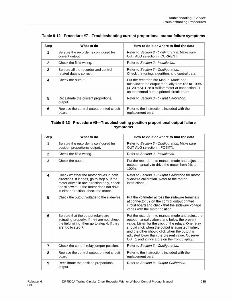
Troubleshooting / ServiceTroubleshooting Procedures
Release H DR4500A Truline Circular Chart Recorder With or Without Control Product Manual 2358/99
Table 9-12 Procedure #7—Troubleshooting current proportional output failure symptoms
Step What to do How to do it or where to find the data
1 Be sure the recorder is configured forcurrent output.
Refer to Section 3 - Configuration. Make sureOUT ALG selection = CURRENT.
2 Check the field wiring. Refer to Section 2 - Installation.
3 Be sure all the recorder and controlrelated data is correct.
Refer to Section 3 - Configuration.Check the tuning, algorithm, and control data.
4 Check the output. Put the recorder into Manual Mode andraise/lower the output manually from 0% to 100%(4–20 mA). Use a milliammeter at connection J1on the control output printed circuit board.
5 Recalibrate the current proportionaloutput.
Refer to Section 8 - Output Calibration.
6 Replace the control output printed circuitboard.
Refer to the instructions included with thereplacement part.
Table 9-13 Procedure #8—Troubleshooting position proportional output failuresymptoms
Step What to do How to do it or where to find the data
1 Be sure the recorder is configured forposition proportional output.
Refer to Section 3 - Configuration. Make sureOUT ALG selection = POSITN.
2 Check the field wiring. Refer to Section 2 - Installation.
3 Check the output. Put the recorder into manual mode and adjust theoutput manually to drive the motor from 0% to100%.
4 Check whether the motor drives in bothdirections. If it does, go to step 5. If themotor drives in one direction only, checkthe slidewire. If the motor does not drivein either direction, check the motor.
Refer to Section 8 - Output Calibration for motorslidewire calibration. Refer to the motorinstructions.
5 Check the output voltage to the slidewire. Put the voltmeter across the slidewire terminalsat connector J2 on the control output printedcircuit board and check that the slidewire voltagevaries with the motor position.
6 Be sure that the output relays areactuating properly. If they are not, checkthe field wiring, then go to step 4. If theyare, go to step 7.
Put the recorder into manual mode and adjust theoutput manually above and below the presentvalue. Listen for the click of the relays. One relayshould click when the output is adjusted higher,and the other should click when the output isadjusted lower than the present value. ObserveOUT 1 and 2 indicators on the front display.
7 Check the control relay jumper position. Refer to Section 3 - Configuration.
8 Replace the control output printed circuitboard.
Refer to the instructions included with thereplacement part.
9 Recalibrate the position proportionaloutput.
Refer to Section 8 - Output Calibration.

Troubleshooting / ServiceTroubleshooting Procedures
236 DR4500A Truline Circular Chart Recorder With or Without Control Product Manual Release H 8/99
Table 9-14 Procedure #9—Troubleshooting relay output failure symptoms
Step What to do How to do it or where to find the data
1 Be sure the recorder is configured forrelay output.
Refer to Section 3 - Configuration. Make sureOUT ALG selection = TIME.
2 Be sure all the recorder and controlrelated data is correct.
Refer to Section 3 - Configuration .Check the Tuning, Algorithm, and Control data.
3 Check that the applicable output relayactuates properly. If it does, go to step 4.
Put the recorder into manual mode and adjust theoutput manually to raise or lower the PV aroundthe setpoint. Listen for the click of the relay as thePV moves in either direction. Observe OUT 1 or 2indicator on the front display.
4 Check the control relay jumper positions. Refer to Section 3 - Configuration.
5 Check the field wiring. Refer to Section 2 - Installation.
6 Replace the control output printed circuitboard.
Refer to the instructions included with thereplacement part.
Table 9-15 Procedure #10—Troubleshooting current/time or time/current failuresymptoms
Step What to do How to do it or where to find the data
1 Be sure the recorder is configured forcurrent time/time current output.
Refer to Section 3 - Configuration. Make sureOUT ALG selection = TI CUR or CUR TI.
2 Be sure all the recorder and controlrelated data is correct.
Refer to Section 3 - Configuration.Check the tuning, algorithm, and control data.
3 Check that the applicable output relayactuates properly. If it does, go to step 4.If it does not check the field wiring; thengo to step 5.
Put the recorder into manual mode and adjust theoutput manually to raise or lower the PV aroundthe setpoint. Listen for the click of the relay as thePV moves in either direction. Observe OUT 1 or 2indicator on the front display.
4 Check the control relay jumper positions. Refer to Section 3 - Configuration.
5 Check the current proportional output. Put the recorder in manual mode and manuallyadjust the output from 0 to 100% (4–20 mA). Usea milliammeter across the terminals in connectorJ1 on the control output printed circuit board toverify the output.
6 Recalibrate the current output. Refer to Section 8 - Output Calibration.
7 Replace the control output printed circuitboard.
Refer to the instructions included with thereplacement part.

Troubleshooting / ServiceTroubleshooting Procedures
Release H DR4500A Truline Circular Chart Recorder With or Without Control Product Manual 2378/99
Table 9-16 Procedure #11—Troubleshooting the auxiliary output
Step What to do How to do it or where to find the data
1 Be sure the controller is configured forAuxiliary Output.
Refer to Subsection 3.13 – Options Set UpGroup. Make sure AUX OUT is enabled and thecorrect parameter is chosen. Check the High andLow Scale values.
2 Check the field wiring. Refer to Section 2 – Installation.
3 Check the output. Use a milliammeter at connection J2 on theAuxiliary Output printed circuit board to determinethe correct output based on your representationof 4 mA and 20 mA.
4 Recalibrate the Auxiliary Output. Refer to Subsection 8.4 – Auxiliary OutputCalibration.
5 Replace the Auxiliary Output printedcircuit board.
Refer to the instructions included with thereplacement part.
Table 9-17 Procedure #12—Troubleshooting external alarm function failure symptoms
Step What to do How to do it or where to find the data
1 Be sure all the alarm configuration datais correct.
Refer to Section 3 - Configuration.
2 Check the applicable alarm relay jumperposition.
Refer to Section 3 - Configuration.
3 Check the field wiring. Refer to Section 2 - Installation.
4 Check that the applicable alarm relayactuates properly depending on ALARMTYPE configuration selection.
Alarms can be triggered either by:
• reconfiguring the value of the trip points(AnSnVAL), or
• connecting a signal generator to the inputand setting the generator level beyond thetrip-point values.
Table 9-18 Procedure #13—Troubleshooting Modbus communications
Step What to do How to do it or where to find the data
1 Check the field wiring and terminationresistor.
Refer to Figure 2-18 in Section 2 – Installation inthis manual.
2 Make sure the Modbus Communicationsboard is properly installed in therecorder.
Open the recorder door and chart plate, andinspect the board. Refer to Figure 10-4 forlocation of the board.
3 Run a Loopback test. Refer to Modbus Communications manual51-52-25-65 for loopback information.

Troubleshooting / ServiceTroubleshooting Procedures
238 DR4500A Truline Circular Chart Recorder With or Without Control Product Manual Release H 8/99

Release H DR4500A Truline Circular Chart Recorder With or Without Control Product Manual 2398/99
10. Parts List
10.1 Overview
Introduction
This section provides the replacement parts lists for the DR4500A Truline Recorder. Most parts aresupplied on an optimum replacement unit basis; that is, part numbers are given for complete printed circuitboards rather than for individual PCB components.
The figures that follow are exploded views of the DR4500A recorder. Each part is labeled with a keynumber and the key numbers are listed in tables with associated part number.
Also included for your reference are an Internal Cabling drawing (Figure 10-5) and an Internal WiringDiagram (Figure 10-6) for options only.
When ordering parts, be sure to specify your recorder’s serial and model numbers (on nameplate) as well asthe part identification.
What’s in this section?
This section contains the following topics:
Topic See Page
10.1 Overview 239
10.2 Exploded ViewsFigure 10-1 Door assemblyFigure 10-2 Chart plate assemblyFigure 10-3 Basic recorder components without optionsFigure 10-4 Recorder components associated with options
240240241242244
10.3 Miscellaneous Hardware Kit Contents 246
10.4 Figure 10-5 Internal Cabling Data 247
10.5 Figure 10-6 Internal Wiring Diagram – Options Only 248

Parts ListExploded Views
240 DR4500A Truline Circular Chart Recorder With or Without Control Product Manual Release H 8/99
10.2 Exploded Views
Door assembly
Figure 10-1 is an exploded view of the Door Assembly. Table 10-1 is a list of the associated part numbers.
1-1
21452
1-2
1
1-3
1-1
1-2
1-4
1-3A
Figure 10-1 Door assembly
Table 10-1 Door assembly parts
RecommendedSpare Parts perKey Part Number Description
10 100
Quantityper Unit
130754955-50130754955-50430754955-50530754955-50630754955-50730754955-50851197761-501
51197761-50251197761-50351197761-50451404781-501
51404781-502
51404781-503
Door AssemblyBlue with glass window and latchBlue with acrylic window and latchGray with glass window and latchGray with acrylic window and latchBlack with glass window and latchBlack with acrylic window and latchHeavy duty with acrylic window/heavy
duty latch (Before 3/99)HTST door with heavy duty latch (Before 3/99)Heavy duty door with lock (Before 3/99)Heavy duty HTST door with lock (Before 3/99)NEMA 4/Heavy Duty door with Acrylic window
(After 3/99)NEMA 4/heavy Duty door for HTST with Acrylic window (After 3/99)NEMA 4/ Heavy Duty door with Glass window
(After 3/99)
1
1-1 (K)30755980-001 Hinge Pin (Note 1) 21-2 (K)30755980-001 Retaining Ring (Note 1) 21-3
1-3A51309609-50330755980-006
Latch/Lock Assembly Kit (Note 2)Key kit for keyed latch or lock
1 3 1
1-4 30755136-502 Truline Door Overlay 1
NOTE 1: For Door 30754955-50X, (K) denotes that these parts are included in the miscellaneous hardware kit 30755980-001. For all otherdoors, the parts are included with applicable door assembly.
NOTE 2: For Heavy Duty doors only (before 3/99); for knob type latch, order kit 30756584-001; for latch with lock and key, order kit30756584-002. For Heavy Duty & NEMA4 doors (After 3/99); for knob type latch, order 51404673-501; for latch with lock &Key, order 51404673-502.

Parts ListExploded Views
Release H DR4500A Truline Circular Chart Recorder With or Without Control Product Manual 2418/99
Chart plate
Figure 10-2 is an exploded view of the Chart Plate Assembly.Table 10-2 is a list of the associated part numbers.
8 9
3
4756
1
2
21453
10
Figure 10-2 Chart plate assembly
Table 10-2 Chart plate assembly parts
RecommendedSpare Parts perKey Part Number Description
10 100
Quantityper Unit
1 30756304-50130756304-502
Truline Pen Arm Assembly (high speed)Truline Pen Arm Assembly (abrasion resistant)
1 5 1
2 30754957-501 Membrane Switch Key Pad 1 5 13 (K)30756150-001 Chart Hub Kit 1 3 24 30756113-501 Chart Motor 1 3 15 30757571-501 Display PCB (includes key no. 6) 1 5 16 See above Ribbon Cable, Display (included with key no. 5)7 See below Servo Motor Assembly (included with key no. 8)8 30754975-503 Servo Plate Assembly (includes key no. 7) 1 2 19 (K)30755980-002 Spring, tension 1
10 30754977-50330754977-50430754977-51330754977-514
Chart plate for standard (high speed) penChart plate for abrasion resistant penChart plate for std. (high speed) pen - CE MarkChart plate for abrasion resistant pen - CE Mark
1 2 1

Parts ListExploded Views
242 DR4500A Truline Circular Chart Recorder With or Without Control Product Manual Release H 8/99
Basic recorder components without options
Figure 10-3 is an exploded view of the basic recorder components.Table 10-3 is a list of the associated part numbers.
1 4 5 4
32
7 46 21454
Figure 10-3 Basic recorder components without options
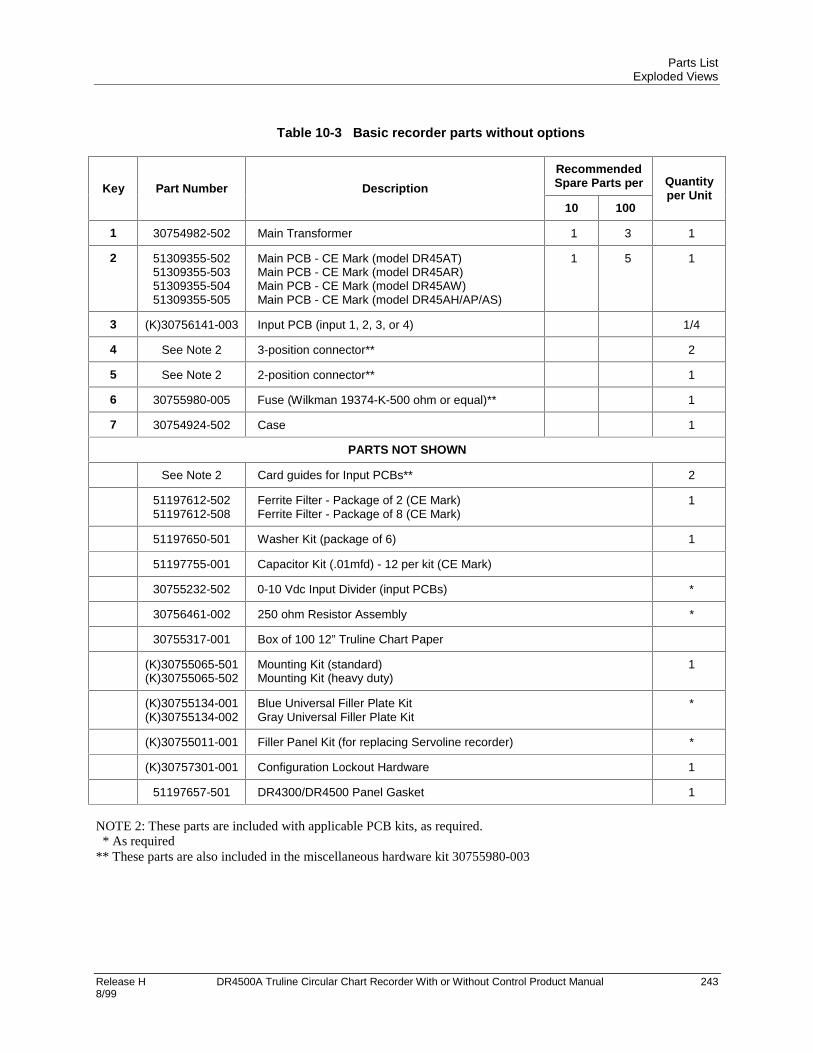
Parts ListExploded Views
Release H DR4500A Truline Circular Chart Recorder With or Without Control Product Manual 2438/99
Table 10-3 Basic recorder parts without options
RecommendedSpare Parts perKey Part Number Description
10 100
Quantityper Unit
1 30754982-502 Main Transformer 1 3 1
2 51309355-50251309355-50351309355-50451309355-505
Main PCB - CE Mark (model DR45AT)Main PCB - CE Mark (model DR45AR)Main PCB - CE Mark (model DR45AW)Main PCB - CE Mark (model DR45AH/AP/AS)
1 5 1
3 (K)30756141-003 Input PCB (input 1, 2, 3, or 4) 1/4
4 See Note 2 3-position connector** 2
5 See Note 2 2-position connector** 1
6 30755980-005 Fuse (Wilkman 19374-K-500 ohm or equal)** 1
7 30754924-502 Case 1
PARTS NOT SHOWN
See Note 2 Card guides for Input PCBs** 2
51197612-50251197612-508
Ferrite Filter - Package of 2 (CE Mark)Ferrite Filter - Package of 8 (CE Mark)
1
51197650-501 Washer Kit (package of 6) 1
51197755-001 Capacitor Kit (.01mfd) - 12 per kit (CE Mark)
30755232-502 0-10 Vdc Input Divider (input PCBs) *
30756461-002 250 ohm Resistor Assembly *
30755317-001 Box of 100 12” Truline Chart Paper
(K)30755065-501(K)30755065-502
Mounting Kit (standard)Mounting Kit (heavy duty)
1
(K)30755134-001(K)30755134-002
Blue Universal Filler Plate KitGray Universal Filler Plate Kit
*
(K)30755011-001 Filler Panel Kit (for replacing Servoline recorder) *
(K)30757301-001 Configuration Lockout Hardware 1
51197657-501 DR4300/DR4500 Panel Gasket 1
NOTE 2: These parts are included with applicable PCB kits, as required. * As required** These parts are also included in the miscellaneous hardware kit 30755980-003

Parts ListExploded Views
244 DR4500A Truline Circular Chart Recorder With or Without Control Product Manual Release H 8/99
Additional recorder components associated with options
Figure 10-4 is an exploded view of the recorder components associated with options.Table 10-4 is a list of the associated part numbers.
7-1 7 1 11 10 5 4 8 9
2 3 13
2145512 9
Figure 10-4 Recorder components associated with options

Parts ListExploded Views
Release H DR4500A Truline Circular Chart Recorder With or Without Control Product Manual 2458/99
Table 10-4 Recorder parts associated with options
RecommendedSpare Parts perKey Part Number Description
10 100
Quantityper Unit
1 30754922-50130754922-502
Second Control Output PCBSecond Current Output PCB - Current Out Only
(Note 4)
1
2 30754922-50130754922-502
First Control Output PCBFirst Control Output - PCB - Current Out Only
1 5 1
30754499-005 Control Output Relay Kit (2 relays per kit) 1 5 2
3 51404561-501
51404561-50251404561-503
Auxiliary Output PCB (includes terminal blocks andcard guides as required)RS485 Modbus RTU Communications PCBRS485 Modbus RTU plus Auxiliary Output PCB
1 5 1
4 (K)30756140-001 Alarm output/digital input PCB kit 1
5 See Note 330755119-501
Ribbon cable (34 conductor) 1 3 1
7 30755127-502 Light accessory kit 1
7-1 (K)30749598-501 Kit of 5 Bulbs (General Instruments 1828 orequivalent)
1
8 (K)30756140-001 Spacers 4
9,10,11
(K)30756141-003 Input PCBs (1, 2, 3, or 4) 1 5 1/4
12 30754919-501 Mother board 1 3 0/1
13 30755980-004 Battery (Duracell DL2450 or equivalent) 1 1 1
NOTE 3: Part included with alarm output/digital input PCB kit 30756140-001.NOTE 4: 30754922-502 Control Output board is used for Table II Options 60 or 66.

Parts ListMiscellaneous Hardware Kit Contents
246 DR4500A Truline Circular Chart Recorder With or Without Control Product Manual Release H 8/99
10.3 Miscellaneous Hardware Kit Contents
Kit contents
Table 10-5 lists the kit contents of miscellaneous hardware kit — part number 30755980-TAB.
Table 10-5 Miscellaneous hardware kit
Quantity
Part Description Tab001
Tab002
Tab003
Tab004
Tab005
Tab006
Pen lifter/retainer 1
Screw 10-32, 3/4” lg. 5
O-ring 5
Spring, tension 2
Hinge pin 2
Retaining ring 2
Pen arm #1 (classic) 1
Pen arm #2 (classic) 1
Latch without lock 1
Latch pin 1
Latch gasket 1
Card guide 2
4-position connector 2
3-position connector 2
3-position connector—CE Mark 2
2-position connector 2
Fuse 0.5A, 250V 20
Batteries 3.0V Lithium Button Cell 5
Key for latch or lock 1
Key for NEMA 4 Door/Keyed latch 1

Parts ListInternal Cabling Data
Release H DR4500A Truline Circular Chart Recorder With or Without Control Product Manual 2478/99
10.4 Internal Cabling Data
View of internal cabling
Figure 10-5 is a view of the internal cabling for the DR4500A Truline Recorder.
Mother board
J81 J13
J14
1
Chassis ground
1
J16 J15
Main board
J4 J7
J3
Alarm/digital inputs J2
J1 1
J8
Chart Plate
Display board
30755064-001, 20 conductor ribbon cable
4 conductor cable
4 conductor cable
4 conductor cable
2 wires (black)
Chassis groundPen Motor
Pen stylus
Chart motor
J5 J9J6
Optical sensor
Pen drive
Chart drive
Password jumper
1 1 1
Main transformer
9 position keyboard cableOptical sensor assembly
J2
J3
2 wire purple pair 2 wire
orange pair2 wire
black pair
J12
Pen stylus output
2 wire pair
1
First input
1
J1
1
Second input
1
J1
1
J3
1
J3
Light option
2 wire gray pair
J2
7 cond. cable
J1
4 cond. cable
30755119-00134 cond. ribbon cable
21456
Figure 10-5 Internal cabling for DR4500A Truline recorder

Parts ListInternal Wiring Diagram – Options Only
248 DR4500A Truline Circular Chart Recorder With or Without Control Product Manual Release H 8/99
10.5 Internal Wiring Diagram – Options Only
View of internal option wiring
Figure 10-6 is a view of the internal wiring diagram - options only for the DR4500A Truline Recorder.
Chart Plate
Display board
Pen 2 Motor
Chart motor
9 position keyboard cable
J3
2-wire pair
Light option
Pen 1 Motor
Mother board
J8 1J13
J2
1
J14
Processor card
J2
Alarm/digital inputs
J1 134 cond. ribbon cable
Main transformer
2 wire gray pair 2 wire
orange pair
J12
Second input
1
J1
1
J3Con
trol
Out
put 2
Inpu
t Car
d 4
Inpu
t Car
d 3
Con
trol
Out
put
1
Com
mun
icat
ion
Car
d O
R
Aux
iliar
y O
utpu
t Car
d
4 cond. cable
Ground
Tes
t
1
T1 (See Table 1 for connections)
Conn. Designation on Destinaton Bd.
J1
J1
J4
J4
J4
J2GRN. WHT. BLK. RED
2
2
2
2
2
4
No. of Cond.
Destination (Board)
BLU.
BRN.
ORG.
VIO.
WHT.
Female Conn. GRN, WHT, BLK, RED.
Input Card #3
Processor Card
Input Card #4
Control Output #1
Control Output #2
Auxiliary Output
Main transformerGRN. WHT. BLK. RED
T1 Leads
TABLE 1
Du
al C
on
nec
tor
Mal
e C
on
n.
Fem
ale
Co
nn
.
22767
No Connection
Communication Card (RS485/422)
J4Auxiliary Output/ Communication (RS485/422)
Figure 10-6 Internal diagram for DR4500A Truline recorder – options only

Release H DR4500A Truline Circular Chart Recorder With or Without Control Product Manual 2498/99
A. Model DR45AR
A.1 Overview
Introduction
If the key number for your recorder is DR45AR, it is a relay expansion model Truline recorder that canhave up to six alarm relay outputs and include Fo calculation function. While its basic functions areidentical to the standard (DR45AT) Truline recorder, it does have some unique hardware, wiring andconfiguration features. This section provides the data pertinent to these unique features as a supplement tothe standard Truline in this product manual.
What’s in this section
The table below lists the topics that are covered in this section.
Topic See Page
A.1 Overview 249
A.2 Hardware Identification 250
A.3 Fo Reset Configuration 252
A.4 Options Configuration 253
A.5 Operations Additions 255
A.6 Configuration Worksheet Additions 256

Model DR45ARHardware Identification
250 DR4500A Truline Circular Chart Recorder With or Without Control Product Manual Release H 8/99
A.2 Hardware Identification
Introduction
Figure A-1 (DR45AR with one input) and Figure A-2 (DR45AR with two to four inputs) identify thehardware components of the DR45AR model versus "Table" selections.
DR45AR with one input
Figure A-1 identifies the hardware components of the DR45AR with one input.
Number 5 & 6 Alarm outputs PCB *Table III - 0X3
#1
4-20mA control output #1 PCB *Table II = 40 and Number 3 & 4 Alarm outputs PCB *Table III - 0X2, 0X3
Mother PCB (for control and selected options)
Number 1 & 2 Alarm output/ digital input PCB *Table III - 0X1, 0X2 or 0X3
Main PCB(common)
#1 Input PCB *Table I - 1000, 3000
VIEW A - - Key Number: DR45AR With one input
21464
* Refer to Model Selection Guide
Figure A-1 DR45AR with one input

Model DR45ARHardware Identification
Release H DR4500A Truline Circular Chart Recorder With or Without Control Product Manual 2518/99
DR45AR with two to four inputs
Figure A-2 identifies the hardware components of the DR45AR with two to four inputs.
4-20mA control output #1 PCB *Table II = 40 and Number 3 & 4 Alarm outputs PCB *Table III - 0X2, 0X3
Mother PCB (for inputs #3 , control and selected options)
Number 1 & 2 Alarm output/ digital input PCB *Table III - 0X1, 0X2 or 0X3
4-20 mA Control Output #2 and Number 5 & 6 Alarm outputs PCB *Table III - 0X3
#3#4 #2 #1
Main PCB (common)
Input PCB’s *Table I - XXXX x = 0,1, or 3
VIEW B - - Key Number: DR45AR With two to four inputs
21465* Refer to Model Selection Guide
Figure A-2 DR45AR with two to four inputs

Model DR45ARFo Reset Configuration
252 DR4500A Truline Circular Chart Recorder With or Without Control Product Manual Release H 8/99
A.3 Fo Reset Configuration
Introduction
This SET UP group is specific to Model DR45AR. It allows you to reset the Fo sterilization calculation.
Accessing Fo reset prompts
Press the SET UP key until you see:
Upper Display: SET UP
Lower Display: FO RESET
Press the FUNC key to call up the Fo Reset function prompt that will allow you to reset the Fo sterilizationcalculation. The function prompt for the Fo Reset group is listed in Table A-1.
Function prompts
Table A-1 lists the function prompt in the “Fo RESET” Set Up group for model DR45AR.
Table A-1 Fo RESET group function prompts
Function PromptLower Display
Function Name Selections or Range of SettingUpper Display
FactorySetting
RESET Fo Reset Fo SterilizationCalculation
(REM SW or REM SW2under "OPTIONS" groupmust be configured for"FO RST".)
NOYES

Model DR45AROptions Configuration
Release H DR4500A Truline Circular Chart Recorder With or Without Control Product Manual 2538/99
A.4 Options Configuration
Introduction
For Model DR45AR there are several additions to be added to Table 3-18 Options Group Function Prompts(from Section 3). They cover additional options that are only available with this model number.
Table A-3 on the next page shows the additions made for Model DR45AR in the options group definitions.
Table A-2 Options group function prompts, continued from Section 3/Table 3-17
Function PromptLower Display
Function Name Selections or Range of SettingUpper Display
FactorySetting
STERILIZ Fo Sterilization Time YESNO
IN TEMP Input for ProductTemperature
INPUT 1INPUT 2INPUT 3INPUT 4
STDTEMP Standard ReferenceTemperature
0.1 to 9999
Z VALUE Thermal Resistance 0.1 to 9999
REM SW Remote Switching NONETO MAN (from AUTO)TO LSP (from REMOTE)TO 2SP (from LSP)TO DIR (from REV)TO HOLD (from RUN)TUNEFO RST
REM SW2 Remote Switching — digitalinput 2
NONEFO RST

Model DR45AROptions Configuration
254 DR4500A Truline Circular Chart Recorder With or Without Control Product Manual Release H 8/99
Table A-3 Option group definitions, continued from Section 4/Table 4-15
Lower DisplayPrompt
Upper DisplayRange of Setting or Selection
Parameter Definition
STERILIZ YES (activates Fo sterilizationcalculation)NO
Fo STERILIZATION TIME — This function computesequivalent sterilization time by accumulating lethalityrates for a product over each 1/3 or 2/3 second scaninterval of the recorder using this equation:
Ts = Ts(t-1) + dt X 10(t–Tb)
z
Where:Ts = sterilization time in minutes
Ts(t-1) = previous sterilization timedt = time interval (1/3 or 2/3 second)
NOTE: 1/3 second if less than 3configured inputs; 2/3 second if greaterthan 2 configured inputs.
Tb = standard reference temperature (configurable)
t = product (input) temperature (°F or °C)z = thermal resistance (configurable)
Only applicable if Model Table II is 40, Model Table III is0X3, and Model Table IV is F.
INTEMP INPUT 1INPUT 2INPUT 3INPUT 4
INPUT FOR PRODUCT TEMPERATURE — selectswhich input will supply product temperature forsterilization calculation.
STDTEMP 0.1 to 9999 STANDARD REFERENCE TEMPERATURE — selectsa reference temperature constant for sterilizationcalculation -- usually 250°F or 121°C.
Z VALUE 0.1 to 9999 THERMAL RESISTANCE — selects a thermalresistance constant for sterilization calculation -- usually18°F or 10°C.
REM SW
NONETO MAN (from AUTO)TO LSP (from REMOTE)TO 2SP (from LSP)TO DIR (from REV)TO HOLD (from RUN)TUNEFO RST
REMOTE SWITCHING — allows you to select an actionto be initiated by remote contact closure through digitalinput .
NONE — No SelectionTO MAN — switch to manual mode from automaticTO LSP — switch to local setpoint from remoteTO 2SP — switch to 2nd setpoint from local setpointTO DIR — switch to direct output action from reverseTO HOLD — put ramp/soak program in holdTUNE — start AccutuneFO RST — reset sterilization calculation.
REM SW2 NONEFO RST
REMOTE SWITCHING DIGITAL 2 INPUT — allows youto select remote contact closure through digital 2 inputto reset sterilization calculation or not.

Model DR45AROperations Additions
Release H DR4500A Truline Circular Chart Recorder With or Without Control Product Manual 2558/99
A.5 Operations Additions
Introduction
In addition to the standard operating functions in this manual the additions listed below appear if you havemodel DR45AR.
Viewing FO sterilization display
Add the following prompt to Table 5-5 Lower Display Key Parameter Prompts.
Prompt Description
FO FO sterilization time in the lower display with the appropriate input in the upperdisplay
Digital input (REM SW) prompt selection
Add the following selections to Table 5-22 Digital Input Option Action on Contact Closure.
REM SWSelections
Display Indication Action on Contact Closure
FO RST None Resets FO sterilization calculation — if FO RESETprompt is enabled.

Model DR45ARConfiguration Worksheet Additions
256 DR4500A Truline Circular Chart Recorder With or Without Control Product Manual Release H 8/99
A.6 Configuration Worksheet Additions
Configuration additions
In addition to the Configuration worksheet items that are listed in Section 3 - Configuration, the followingparameters also appear in Model DR45AR.
GroupPrompt
Functionprompt
Value orSelection
FactorySetting
FO RESET
OPTIONS
RESET FO
REJ FREQHF REJRELHUMIDATMPRESDEVIATIONDEVSETPTSCROLLGRANDTOTSTERILIZIN TEMPSTDTEMPZ VALUEREM SWREM SW2
_______
__________________________________________________________________________________________________
60 ENABLENO—NONE0NONEDISABL

Release H DR4500A Truline Circular Chart Recorder With or Without Control Product Manual 2578/99
B. Security Lockout
B.1 Overview
Introduction
Your recorder has a security bypass code which allows you to enter secured areas if you have forgotten orlost the operator security code.
To use the universal password, go to the Lockout Set Up group. At PASSWORD enter 1502. Thisoverrides the existing password.
Be sure to re-enter a new password to lockout any unauthorized changes to the recorder’s configuration andcalibration prompts.
ATTENTION
Remove this page for security.

Security LockoutOverview
258 DR4500A Truline Circular Chart Recorder With or Without Control Product Manual Release H 8/99


Release H DR4500A Truline Circular Chart Recorder With or Without Control Product Manual8/99
Index
00-10 Volt dc inputs, 340–10 Volt inputs, 206
44-20 mA auxiliary output wiring, 494-20 mA control output wiring, 364-20 mA input wiring, 324–20 mA inputs, 207
AAC line power, 27Accutune II, 155Alarm hysteresis, 76, 123Alarm messages, 143Alarm outputs, 42Alarm setpoints, 159Alarms group definitions, 122Atmospheric pressure compensation, 79, 127Automatic calibration mode, 217Automatic local mode, 145Automatic mode
Return to, 146, 180Selecting, 146
Automatic remote mode, 145Automatic switchover, 105Automatic switchover value, 70, 106Auxiliary Output, 76, 77, 81
BBasic recorder components without options, 242Battery test failure, 229Baud rate, 78Bias, 107Bias for remote setpoint, 70Burnout, 63Burnout protection, 93
CCalibration procedure, 208Calibration set up, 200
0-10 Volt inputs, 2064-20 mA inputs, 207Millivolts and Volts inputs (except 0-10 Volts), 205RTD inputs, 204Thermocouple inputs using a compensated calibrator
method, 202Thermocouple inputs using an ice bath, 201
Thermocouple inputs using the ambient temperaturemethod, 203
CE Conformity (Europe), 1CE Conformity special conditions, 7CE conformity special conditions (Europe), 24Chart high range value, 94Chart lamp, 165
Replacing, 165Chart low range value, 94Chart name, 65, 67, 97Chart plate assembly parts, 241Chart speed selection, 65, 67CHN indicator, 144Circuit-breaker, 27Cleaning, 165Communications station address, 78, 126Condensed specifications, 8Configuration procedure, 60Configuration prompts, 55Configuration tips, 59Control algorithm, 71, 110Control output direction, 71, 108Controller dropoff value, 71, 108Current proportional output calibration, 214, 219Current simplex, 112Current/relay duplex, 113Current/time duplex range, 71Customer support, 223Cycle time (heat), 117Cycle time 2 (cool), 117
DDeadband, 71, 108Decimal point location, 62, 90Deviation, 127Deviation bargraph, 140Deviation recording action, 79Deviation setpoint value, 79, 127Device status, 226Diagnostic error messages, 142Diagnostic tests, 134Digital inputs, 42Dimensions, 16Direct acting control, 108Display test, 135Displaying totalizer value, 163Displays, 3
EElectrical noise, 24Emissivity, 63Engineering units, 90Error message

Index
DR4500A Truline Circular Chart Recorder With or Without Control Product Manual Release H 8/99
BATT LOW. SeeBATTERY, 229CAL TEST, 228CAL1 ERR, 228CAL2 ERR, 228CONFTEST, 227EE FAIL, 229FACT CRC, 228FAILSAFE, 227INxFAIL, 229PV LIMIT, 229RAM TEST, 227RV LIMIT, 229SW FAIL, 229
Error message prompts, 227Error messages, 142Event message configuration, 80Event pen function, 163Event pen operation, 163
FFactory calibration, 194Failsafe, 225Failsafe output value, 71Failure symptoms, 223Ferrite filter locations (CE Mark), 26Field wiring, 197Filter, 63, 93Fo reset, 252Fo sterilization calculation, 252Fo sterilization time, 253
GGain, 116Gain 2, 117Gain units, 71Grid line contrast, 132, 136
HHardware kit contents, 246Header for chart, 65, 97High output limit, 71, 108High range value, 63, 92High setpoint limit, 70Hours per revolution, 96Hysteresis, 71, 109, 123
IIce bath, 198Indicators, 3Input 1 actuation type, 62Input actuation type, 91Input compensation, 63, 93Input out of range, 230Input terminals, 197Inputs
0–5 Vdc, 30
Radiamatic, mV, 30RTD, 30Thermocouple, 30
InstallationOperating limits, 8Preinstallation information, 7
Installing chart, 166Internal cabling, 247
JJumper positions, 199
KKey test, 135Knockout locations, 17
LLocal setpoint, 147Local setpoint, 106Lockout, 83, 84, 130Lockout password, 83, 84Low flow cutoff selection, 63Low output limit, 71, 108Low range value, 63, 93Low setpoint limit, 70
MMaintenance, 165Manual calibration mode, 217Manual mode, 145
Adjusting output, 146, 147, 179, 180Selecting, 146
Manual reset, 116Minutes per repeat, 110Monitoring your recorder, 138Motor traverse time, 217Mounting
Overall dimensions, 16Mounting methods, 17
Flush in panel, 18, 20Flush in panel, 21Surface, 22
OON/OFF algorithm, 110Operating limits, 8Operating modes, 145Operating parameters, 141Operator functions, 144Operator interface, 3, 138Output algorithm, 71, 112Output wiring for alarms 3 and 4, 44Output wiring for alarms 5 and 6, 45

Index
Release H DR4500A Truline Circular Chart Recorder With or Without Control Product Manual8/99
PParts lists, 239Password, 130PD with manual reset, 111Pen Set Up group, 64Pen tip, 165
Cleaning, 165Physical considerations, 16PID A, 111PID B, 111PID sets, 154Polynomial Equation, 103Position proportional control output wiring, 38Position proportional output calibration, 216Position proportional simplex, 113Power loss, 168Power supply mains, 27Power up controller mode recall, 70, 107Power up diagnostic tests, 134Power-up tests, 225Printing characteristics adjustments, 131, 211Prompt hierarchy, 55Proportional band, 116Proportional band 2, 117Proportional band units, 109
RRadiamatic, millivolts, and volts inputs (except 0–10
Volts), 205Ramp/soak program, 119Rate 2, 117Rate action, 116Rate of integration, 68, 101Ratio, 106Ratio for remote setpoint, 70Recorder components associated with options, 244Recovery from a power loss, 168RECYCL parameter, 181Rejection frequency, 76, 79, 81, 127Relative humidity, 79, 127Relay control output wiring, 40Relay duplex, 113Relay/current duplex, 113Remote chart activation, 66, 98Remote setpoint, 106Remote switching, 161Repeats per minute, 110Replacing chart, 166Reset, 116Reset 2, 117Reset units, 71, 110Resetting totalizer value, 162Resistance equivalent, 196Restoring factory calibration, 194Reverse acting control, 108RS485 Modbus communications wiring, 47RSP, 148RTD inputs, 204
SSafety Requirements for Electrical Equipment, 24Self diagnostics, 223Setpoint high limit, 108Setpoint low limit, 108Setpoint Program
Data entry, 179event setup, 186overview, 169ramp setup, 181run/monitor functions, 190segment setup, 183
Setpoint ramp, 118Configuring, 149Running, 150
Setpoint ramp final setpoint, 119Setpoint ramp time, 119Setpoint selection indication, 148Setpoint source, 70, 106, 147Setpoint tracking, 70, 107Set-up tasks, 5Shield wiring, 26Single setpoint ramp, 118, 149SOKDEV parameter, 181SPPROG parameter, 181Start up, 135Stylus, 132, 136Suppression filters, 26Switchover value, 153
TTemperature units, 62, 90Thermal resistance, 253Thermocouple inputs using a compensated calibrator
method, 202Thermocouple inputs using an ice bath, 201Thermocouple inputs using the ambient temperature
method, 203Three position step control output wiring, 38Time division, 97Time parameters group definitions, 99Totalizer, 68Totalizer group definitions, 100Totalizer reset, 68, 70Totalizer scale factor, 68, 70Totalizer value, 162
Displaying, 163Resetting, 162
Trace line contrast, 132, 136Transmitter characterization, 63, 92Troubleshooting procedures, 232Ttransmitter power, 32Tuning constants, 152Tuning group prompt definitions, 115Tuning messages, 143Tuning parameter sets, 70, 105Two local setpoints, 106Two sets of tuning constants, 152

Index
DR4500A Truline Circular Chart Recorder With or Without Control Product Manual Release H 8/99
VVisual failure symptoms, 223, 231Voltage equivalent, 196
WWake time days, 98Wake time hours, 98Wake time minutes, 98Wake time months, 98Wire bundling, 25Wiring
0-10 Vdc inputs, 340-5 Vdc inputs, 304-20 mA auxiliary output, 494-20 mA control output, 364-20 mA inputs. SeeAC line power. SeeElectrical noise precautions, 24mV inputs, 30Position proportional control output, 38Radiamatic inputs, 30Relay control output, 40RS485 Modbus communications, 47RTD inputs, 30Shields, 26Thermocouple inputs, 30Three position step control output, 38Transmitter power. SeeWire bundling, 25Wiring the recorder, 26
Wiring for PV inputs, 2000-10 Volt inputs, 2064-20 mA inputs, 207Millivolts and Volts inputs (except 0-10 Volts), 205RTD inputs, 204Thermocouple inputs using a compensated calibrator
method, 202Thermocouple inputs using an ice bath, 201Thermocouple inputs using the ambient temperature
method, 203

Fax Transmittal Fax No.: (602) 313-4842
Reader Comments
To: Automation College
From: Name Date:
Title:
Company:
Address:
City: State: Zip:
Telephone: Fax:
DR4500A Truline Circular Chart Recorder With or Without Control, Product Manual,Release H, 8/99
Comments:
You may also call 800-822-7673 (available in the 48 contiguous states except Arizona; in Arizonacall 602-313-5558), email us at [email protected], or write to:
Honeywell Inc.Industrial Automation and ControlAutomation College2820 West Kelton LanePhoenix, AZ 85053-3028
Knowledge Building Tools


Industrial Automation and ControlHoneywell Inc.1100 Virginia DriveFort Washington, PA 19034