InPro 6000 Optical O Sensors Instruction manual ... · PDF fileInPro ®6000 Optical O...
95
InPro ® 6000 Optical O 2 Sensors Instruction manual Bedienungsanleitung Instructions d’utilisation InPro 6000 optical O 2 sensors 52 206 256
Transcript of InPro 6000 Optical O Sensors Instruction manual ... · PDF fileInPro ®6000 Optical O...

InPro®6000Optical O2 Sensors
Instruction manualBedienungsanleitungInstructions d’utilisation
InPro 6000 optical O2 sensors 52 206 256

English Page 3
Deutsch Seite 33
Français Page 65
InPro 6000 optical O2 sensors © 07 / 12 Mettler-Toledo AG52 206 256 Printed in Switzerland
2 InPro 6000 Series Optical O2 Sensors 12 mm

InPro®6000 SeriesOptical O2 Sensors
Instruction manual
© 07 / 12 Mettler-Toledo AG InPro 6000 optical O2 sensors Printed in Switzerland 52 206 256
InPro 6000 Series Optical O2 Sensors 12 mm 3

1 Introduction.....................................................................5
2 Important notes ...............................................................62.1 Notes on operating instructions ..........................................62.2 Intended use ....................................................................62.3 Safety instructions.............................................................72.4 Examples of some typical applications................................8
3 Product description..........................................................93.1 General information...........................................................93.2 Principle ..........................................................................93.3 Scope of delivery ..............................................................93.4 Equipment features .........................................................10
4 Installation....................................................................114.1 Mounting the sensor........................................................114.1.1 Retrofit kit.......................................................................114.2 Connection.....................................................................124.2.1 Connecting the optical sensor to a cable............................124.2.2 Connecting the cable to a transmitter.................................124.2.3 Connect InPro 6860i to a analog (nA) input......................13
5 Operation ......................................................................145.1 Start-up .........................................................................145.2 Configuration..................................................................145.2.1 Sensor detection .............................................................145.2.2 Sampling rate.................................................................145.2.3 LED mode......................................................................145.3 Calibration .....................................................................155.3.1 Purpose of calibration .....................................................155.3.2 Factory calibration ..........................................................165.3.3 Single point calibration (Slope or Process Calibration) ........175.3.4 Slope calibration ............................................................175.3.5 Process calibration ........................................................175.3.6 Dual point calibration ......................................................185.3.7 Calibration when connected with analog signal .................195.3.8 Reset to factory calibration ..............................................195.4 Autoclaving of the InPro 6880i sensor shaft ......................19
6 Maintenance .................................................................206.1 Sensor inspection ...........................................................206.1.1 Visual inspection ............................................................206.1.2 Testing the sensor with the transmitter ...............................206.1.3 ISM ..............................................................................216.2 Replacing the OptoCap ....................................................22
7 Storage .........................................................................23
8 Product specification .....................................................248.1 Certificates .....................................................................248.2 Specifications .................................................................25
9 Ordering information......................................................269.1 Sensors .........................................................................269.2 Accessories....................................................................269.3 Spare parts ....................................................................279.4 Recommended transmitters..............................................279.5 Recommended housings .................................................28
10 Theory of the optical oxygen measurement .....................2910.1 Introduction....................................................................2910.2 Principle ........................................................................2910.3 Principle of the design of the optical oxygen sensor ............2910.4 Temperature ...................................................................3010.5 Dependence on flow........................................................3010.6 Oxygen partial pressure – oxygen concentration .................30
Contents
InPro 6000 optical O2 sensors © 07 / 12 Mettler-Toledo AG52 206 256 Printed in Switzerland
4 InPro 6000 Series Optical O2 Sensors 12 mm

1 Introduction
Thank you for buying the optical oxygen sensor from METTLER TOLEDO.
The construction of INGOLD’s optical oxygen sensorsemploys leading edge tech nology and complies withsafety regulations currently in force. Notwithstandingthis, improper use could lead to hazards for the user ora third-party, and/or adverse effects on the plant or oth-er equipment.
Therefore, the operating instructions must be readand understood by the persons involv ed before workis started with the sensor.
The instruction manual must always be stored close athand, in a place accessible to all people working withthe sensor.
If you have questions, which are not or insufficientlyanswered in this instruction manual, please contactyour METTLER TOLEDO supplier. They will be glad toassist you.
© 07 / 12 Mettler-Toledo AG InPro 6000 optical O2 sensors Printed in Switzerland 52 206 256
InPro 6000 Series Optical O2 Sensors 12 mm 5

2 Important notes
2.1 Notes on operating instructions
These operating instructions contain all the informationneeded for safe and proper use of the optical sensor.
The operating instructions are intended for personnelentrusted with the operation and maintenance of thesensors. It is assumed that these persons are familiarwith the equipment in which the sensor is installed.
Warning notices and symbolsThis instruction manual identifies safety instructionsand additional information by means of the followingsymbols:
This symbol draws attention to safety instructions andwarnings of potential danger which, if neglected,could result in injury to persons and/or damage toproperty.
This symbol identifies additional information and instructions which, if neglected, could lead to defects,inefficient operation and possible loss of production.
2.2 Intended use
METTLER TOLEDO optical O2 sensors are intendedsolely for inline measurement of the oxygen partialpressure, as described in this instruction manual.
Any use of these sensors which differs from or exceedsthe scope of use described in this instruction manualwill be regarded as inappropriate and incompatiblewith the intended purpose. The manufacturer /supplieraccepts no responsibility whatsoever for any damageresulting from such improper use. The risk is borne en-tirely by the user /operator.
Other prerequisites for appropriate use include:
– compliance with the instructions, notes and requirements set out in this instruction manual.
– acceptance of responsibility for regular inspection,maintenance and functional testing of all asso -ci ated components, also including compliancewith local operational and plant safety regulations.
– compliance with all information and warnings given in the documentation relating to the productsused in conjunction with the sensor (housings,transmitters, etc.).
– observance of all safety regulations governing theequipment in which the sensor is installed.
– correct equipment operation in conformance withthe prescribed environmental and operational conditions, and admissible installation positions.
– consultation with Mettler-Toledo Process Analyticsin the event of any uncertainties.
InPro 6000 optical O2 sensors © 07 / 12 Mettler-Toledo AG52 206 256 Printed in Switzerland
6 InPro 6000 Series Optical O2 Sensors 12 mm
2.3 Safety instructions
– The plant operator must be fully aware of the potential risks and hazards attached to operation ofthe particular process or plant. The operator is responsible for correct training of the workforce, forsigns and markings indicating sources of possibledanger, and for the selection of appropriate, state-of-the-art instrumentation.
– It is essential that personnel involved in the commissioning, operation or maintenance of thesesensors or of any of the associated equipment (e.g.housings, transmitters, etc.) be properly trained inthe process itself, as well as in the use and handling of the associated equipment. This includes having read and understood this instruc-tion manual.
– The safety of personnel as well as of the plant itselfis ultimately the responsibility of the plant operator.This applies in particular in the case of plants operating in hazardous zones.
– The oxygen sensors and associated componentshave no effect on the process itself and cannot influence it in the sense of any form of control system.
– Maintenance and service intervals and schedulesdepend on the application conditions, compositionof the sample media, plant equipment and signi -ficance of the safety control features of the measuring system. Processes vary considerably,so that schedules, where such are specified, canonly be regarded as tentative and must in any casebe individually established and verified by the plantoperator.
– Where specific safeguards such as locks, labels, orredundant measuring systems are necessary,these must be provided by the plant operator.
– A defective sensor must neither be installed nor putinto service.
– Only maintenance work described in this operatinginstruction may be performed on the sensors.
– When changing faulty components, use only original spare parts obtainable from your METTLERTOLEDO supplier (see spare parts list, “Section9.3”).
– No modifications to the sensors and the acces-sories are allowed. The manufacturer accepts noresponsibility for damages caused by unauthorisedmodifications. The risk is borne entirely by the user.
© 07 / 12 Mettler-Toledo AG InPro 6000 optical O2 sensors Printed in Switzerland 52 206 256
InPro 6000 Series Optical O2 Sensors 12 mm 7

2.4 Examples of some typical applications
Below is a list of examples of typical fields of applica-tion for the oxygen sensors. This list is not exhaustive.
Measurement in liquids:
– Fermentation
– Bio-Tech
– Food&Beverage
InPro 6000 optical O2 sensors © 07 / 12 Mettler-Toledo AG52 206 256 Printed in Switzerland
8 InPro 6000 Series Optical O2 Sensors 12 mm

3 Product description
3.1 General information
The optical oxygen sensors with integrated tempera-ture probe are used for meas ure ment of oxygen.
The sensors are sterilizable and compatible with CIP(cleaning in place). The sensors InPro 6880 i and InPro 6860i are autoclavable (see chapter 5.4, p.18).
3.2 Principle
The optical oxygen sensors are based on an optical de-tection method, the so called fluorescence quenching.Here is a short summary of the principle. In contrast tothe polarographic Clark-electrode, which detects a redoxreaction of oxygen at the electrode, the optical method isbased on an energy transfer between a chromophore andoxygen.
– A chromophore, embedded in the sensor tip is illumi-nated with blue light. This chromophore absorbs theenergy and if no oxygen is present emits red fluores-cence light with a specific lifetime. This emitted lightis being detected by a detector in the sensor head.
– In the presence of oxygen, the chromophore transfersthe energy to the oxygen molecule. Oxygen is thenable to transfer this energy as heat to the surroundingarea and no fluorescence is emitted.
– The total intensity of the fluorescence and the lifetimeof the fluorescence is related to the Oxygen partialpressure in the medium.
– To analyze the lifetime of the fluorescence, the exci-tation light is pulsed with a constant frequency, theemitted light shows the same course but with a timedelay to the excitation. This delay is called Phase shiftor Phase angle (Phi). The phase shift is dependenton the oxygen level and follows the Stern-Vollmer cor-relation.
– The sensor detects this phase shift and calculates theoxygen concentration.
– The oxygen value ist digitally transferred to thetransmitter.
3.3 Scope of delivery
Each sensor is supplied fully assembled and factorytested and calibrated for correct function together with:
– a quality control certificate
– inspection certificats 3.1(complying with EN10204.3/1B)
– a maintenance cap (not for InPro 6860i)
Important! Each sensor is factory calibrated. The dataare stored in the sensor head. If more then one sensorsof the InPro 6880i are used, pay attention, that the sen-sor head and the sensor shafts are not being mixed.Otherwise a new calibration is necessary and the fac-tory calibration data are not correct.
© 07 / 12 Mettler-Toledo AG InPro 6000 optical O2 sensors Printed in Switzerland 52 206 256
InPro 6000 Series Optical O2 Sensors 12 mm 9

3.4 Equipment features
Two different types of optical sensors are available forthe fermentation application.
The InPro 6880i and the InPro 6860i can be used inapplications where autoclaving is performed. The sen-sor head of the InPro 6880i can be detached and on-ly the sensor shaft is exposed to the high temperature.If the sensor head is not detached during autoclaving,the electronic components may be damaged. The InPro 6860i is fully autoclavable.
The InPro 6870i is intended for use in fermenter, whereonly sterilizations are performed. Here, the sensor headis not exposed to high temperatures.
The InPro 6960i /6970i is intended for use in foodand beverage industry for measuring high and low ppblevel of oxygen respectively.
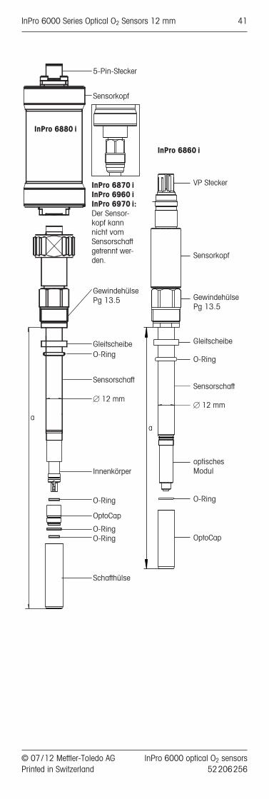
5 Pin connector
Sensor head
Threaded sleevePg 13.5
WasherO-Ring
Sensor shaft
[ 12 mm
Inner body
Temperature probe
O-ring
OptoCap
O-ringO-ring
Cap sleeve
a
InPro 6870 iInPro 6960 iInPro 6970 i: The sensor head is not separable from the sensor shaft.
InPro 6880 i
InPro 6860 i
a
VP connector
Sensor head
Threaded sleevePg 13.5
Washer
O-Ring
Sensor shaft
[ 12 mm
Optical module
O-ring
OptoCap
InPro 6000 optical O2 sensors © 07 / 12 Mettler-Toledo AG52 206 256 Printed in Switzerland
10 InPro 6000 Series Optical O2 Sensors 12 mm

4 Installation
The “Plug & Measure”-concept allows the user to mea-sure oxygen values immediately after installation.
– The sensor is recognized automatically and all rel-evant data are sent to the transmitter, the oxygenvalues are displayed.The sensor is factory calibrated. The factory calibra-tion data are stored in the sensor and do not needto be entered by the user.
4.1 Mounting the sensor
Important! Remove the protection cap before mount -ing the sensor.
Mounting the sensor in a housing
Please refer to the instruction manual of your housingexplaining on how to mount the sensor in place.
Mounting the sensor directly on a pipe or a vessel
The 12 mm sensors can be mounted directly througha socket with inside thread Pg 13.5 and securely tight-ened via the Pg 13.5 threaded sleeve. The sensor canbe mounted in any orientation.
Attention! Do not turn the sensor counter clockwisewhen installed in a housing. The cap sleeve might beloosened.
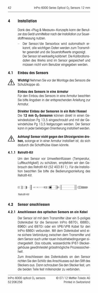
4.1.1 Retrofit kit
For protection of the sensor head against environmen-tal influences (temperature, humidity) the use of theretrofit kit (52 403 811) is recommended. For instal-lation, see the manual of the retrofit kit.
Retrofit kit
© 07 / 12 Mettler-Toledo AG InPro 6000 optical O2 sensors Printed in Switzerland 52 206 256
InPro 6000 Series Optical O2 Sensors 12 mm 11

4.2 Connection
4.2.1 Connecting the optical sensor to a cableThe sensor is connected to the transmitter via a 5 pin data cable for InPro 6870i, 6880i, 6960i and6970i or a VP6/VP8 cable for InPro 6860i. The datacable ensures a secure connection between the trans-mitter and the sensor under harsh industrial conditions.The robust watertight IP67 connector housing guaran-tees maximum process safety.
To connect the data cable to the sensor align the slit ofthe connector with the pin in the plug. Then tightlyscrew the plug to fasten the two parts.
4.2.2 Connecting the cable to a transmitter
Transmitter M400
Note: Cable assignment can be found in the METTLERTOLEDO cable instruction manual.
Note: For connecting the cable to the terminals of thetransmitter, please refer also to the instructions givenin the METTLER TOLEDO transmitter manual.
The cables are available from METTLER TOLEDO in var-ious lengths:
Connect the data cable to the tranmitter as describedin the tables below.
*VP8 only
RS485 cable InPro 6870i/6880i/6960i/6970iM400 M800
Channel 2 Channel 4Color Function TB4 TB2 TB4brown 24DC + 1 9 9black 24DC – 2 10 10gray shield 6 12 12yellow shield 6 15 15blue RS485 – 7 13 13white RS485 + 8 14 14
VP connection to digital inputVP Cables VP8
M400 M800Ch2 Ch4
Color Function TB4 TB2 TB4A black/transp. cathode (nA) n.c n.c n.cB red anode (nA) n.c n.c n.cC gray 24DC + 1 9 9D blue 24DC – 2 10 10E white NTC 22k� n.c n.c n.cF green NTC 22k�(GND) n.c n.c n.cG* pink RS485 + 8 14 14H* brown RS485 – 7 13 13S green/yellow shield 4 12 12
InPro 6000 optical O2 sensors © 07 / 12 Mettler-Toledo AG52 206 256 Printed in Switzerland
12 InPro 6000 Series Optical O2 Sensors 12 mm

4.2.3 Connect InPro 6860i to a analog (nA) input
The InPro 6860i is able to communicate the oxygenvalue as a nA signal and the temperature measurementas a NTC 22K� signal to the biocontroller or an ana-log transmitter. In this situation the sensor behaves asan analog amperometric sensor like (InPro 6800).
Connect the data cable to the transmitter as describedin the table.
*VP8 only
VP connection to analog inputVP Cables VP8 or VP6Color Function analog/nA
A black/transp. cathode (nA) cathodeB red anode (nA) anodeC gray sensor + 24V DC +D blue sensor – 24V DC –E white NTC 22k� NTC 22k�F green NTC 22k�(GND) NTC 22k�(GND)G* pink RS485 + n.c.H* brown RS485 – n.c.S green/yellow shield shield
© 07 / 12 Mettler-Toledo AG InPro 6000 optical O2 sensors Printed in Switzerland 52 206 256
InPro 6000 Series Optical O2 Sensors 12 mm 13

5 Operation
5.1 Start-up
Each sensor is supplied ready to use. Before using remove the protecting cap.
Note: No polarization or calibration is necessary. “Plug and measure” conception.
5.2 Configuration
5.2.1 Sensor detection
Before installing an optical sensor, please refer to themanual for the transmitter and configure the transmit-ter for automatic sensor detection. M800 transmitterdoes not need any pre-configuration.
5.2.2 Sampling rate
Optical oxygen sensors do not measure permanently.Each measurement cycle has a duration of approx.1 second. To prolong the lifetime of an OptoCap, themeasurement interval can be set to any value between1 and 60 seconds. Please choose the appropriate set-ting. Default setting is 10 seconds which is sufficientfor most applications.
5.2.3 LED mode
One contributing factor for the ageing of an OptoCap isthe measurement itself. To prolong the lifetime of theOptoCap, the measurement can be switched off if thesystem is not needed. Especially measurement duringCIP cycles or when the sensor is exposed to high oxy-gen levels during standby of the plant must be avoid-ed. Measurement during CIP cycles can cause highsensor drift
When the sensor is not measuring, the sensor LED isoff. In this state the sensor sends a constant measure-ment value of –1% air to the transmitter and the trans-mitter is set to the “Hold mode”. To configure the “Holdmode” please refer to the transmitter manual.
Automatic switch off at high temperatureIf the LED mode is set to “Auto” (default setting) the sen-sor LED will be switched off as soon as a specificprocess temperature is reached. The default temperatureset points are different for the different optical sensors.
TemperaturesMaximum operat- Default switch ing temperature off temperature
InPro 6860i 60°C/140°F 60°C/140°FInPro 6870i 60°C/140°F 60°C/140°FInPro 6880i 60°C/140°F 60°C/140°FInPro 6960i 40°C/104°F 40°C/104°FInPro 6970i 40°C/104°F 40°C/104°F
InPro 6000 optical O2 sensors © 07 / 12 Mettler-Toledo AG52 206 256 Printed in Switzerland
14 InPro 6000 Series Optical O2 Sensors 12 mm

This limit can be set to an individual value by the user.Using the transmitter (M400 ot M800) or with iSense.These settings are also active if the sensor is connectedto the process with an analog connection (nA). Theswitch off temperature should be set at least 5° higherthen the highest process temperature. For example, if theprocess temperature is 37°C/99°F, 42°C/ 104°Fshould be the minimum set-point. In this situation, assoon as the temperature exceeds 42°C/ 104°F the sen-sor will stop measuring and the LED will be switched off.For the switch on, a hysteresis of 3° is implemented,meaning that the sensor (and LED) will be switched onas soon as the temperature drops below 39°C/101°F.
Manual switch off of the sensor (M400/M800 transmitter)The sensor can be switched off manually via the trans-mitter menu (see the transmitter manual) by setting theLED mode to “off”. To restart the measurement, the LEDmode needs to be set manually to “on” via the trans-mitter menu, or via a remote signal (digital input).
Remote switch off of the sensor(M400/M800 transmitter)The M400 transmitter can be set to “Hold” by applyingan external digital signal (see the transmitter manual).In this situation the sensor and the sensor LED areswitched off. As soon as the “Hold Mode” is off, the op-tical sensor will continue to measure using the previ-ous settings.
5.3 Calibration
5.3.1 Purpose of calibration
Information about the calibration, you find also in themanual of the transmitter.
Calibration should be performed at least after eachchange of the OptoCap, sterilizing or after autoclavingthe sensor.
Since the correlation between the measured phase andthe oxygen value is not linear, a calibration of an opti-cal sensor must be performed very accurately. Wrongcalibrations may significantly reduce the measurementaccuracy and result in incorrect calculation of the Dynamic Lifetime Indicator (DLI) and the Adaptive Cal-ibration Timer (ACT).
Each oxygen sensor has its own individual phase angle at zero oxygen (phi 0) and hundred percent airsaturation (phi 100). Both values are subject to change,for example, after exchange of OptoCap or because ofnormal ageing of the OptoCap.
Depending on the sensor type several methods for cal-ibration are available for the optical oxygen sensors.The highest measurement accuracy is achieved byperforming a 2-point calibration with air and a zero gase.g. N2 or CO2 with a purity of at least 99.9%. For theInPro 6970i a purity of 99.99% is required.
© 07 / 12 Mettler-Toledo AG InPro 6000 optical O2 sensors Printed in Switzerland 52 206 256
InPro 6000 Series Optical O2 Sensors 12 mm 15
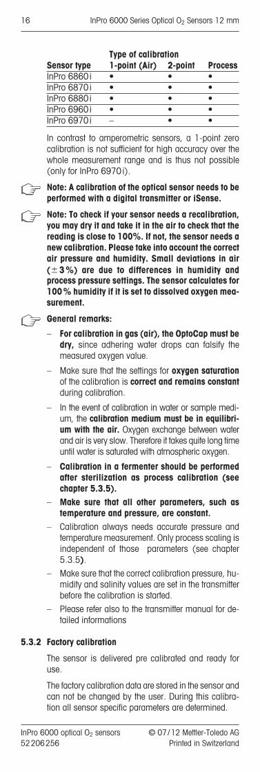
Type of calibrationSensor type 1-point (Air) 2-point ProcessInPro 6860i • • •InPro 6870i • • •InPro 6880i • • •InPro 6960i • • •InPro 6970i – • •
In contrast to amperometric sensors, a 1-point zerocalibration is not sufficient for high accuracy over thewhole measurement range and is thus not possible(only for InPro 6970i).
Note: A calibration of the optical sensor needs to beperformed with a digital transmitter or iSense.
Note: To check if your sensor needs a recalibration,you may dry it and take it in the air to check that thereading is close to 100%. If not, the sensor needs anew calibration. Please take into account the correctair pressure and humidity. Small deviations in air(�3%) are due to differences in humidity andprocess pressure settings. The sensor calculates for100% humidity if it is set to dissolved oxygen mea-surement.
General remarks:
– For calibration in gas (air), the OptoCap must bedry, since adhering water drops can falsify themeasured oxygen value.
– Make sure that the settings for oxygen saturationof the calibration is correct and remains constantduring calibration.
– In the event of calibration in water or sample medi-um, the calibration medium must be in equilibri-um with the air. Oxygen exchange between waterand air is very slow. Therefore it takes quite long timeuntil water is saturated with atmospheric oxygen.
– Calibration in a fermenter should be performedafter sterilization as process calibration (seechapter 5.3.5).
– Make sure that all other parameters, such as temperature and pressure, are constant.
– Calibration always needs accurate pressure andtemperature measurement. Only process scaling isindependent of those parameters (see chapter5.3.5).
– Make sure that the correct calibration pressure, hu-midity and salinity values are set in the transmitterbefore the calibration is started.
– Please refer also to the transmitter manual for de-tailed informations
5.3.2 Factory calibration
The sensor is delivered pre calibrated and ready foruse.
The factory calibration data are stored in the sensor andcan not be changed by the user. During this calibra-tion all sensor specific parameters are determined.
InPro 6000 optical O2 sensors © 07 / 12 Mettler-Toledo AG52 206 256 Printed in Switzerland
16 InPro 6000 Series Optical O2 Sensors 12 mm

For continuous applications, we recommend periodicrecalibration in line with your requirements on accuracy, the type of process in operation and yourown experience. The frequency of the need for re- calibration depends very much on the specific application, and therefore appropriate intervals cannotbe exactly defined here.
5.3.3 Single point calibration (Slope or Process Calibra-tion)
For most applications, a single point calibration shouldbe sufficient, as long as not the whole measuring rangeof the sensor is used.
By carrying out a single point calibration, the factualphase at the desired oxygen value e.g. at hundred per-cent oxygen (phi 100) of the sensor can be established.The corresponding calibration curve is calculated.
5.3.4 Slope calibration (InPro 6870i, InPro 6880i andInPro 6960i)
For most applications where oxygen levels between10% and 200% Air saturation are measured a singlepoint slope calibration is sufficient to reach the re-quired accuracy.
The calibration medium can be either air or a calibra-tion gas with known O2 concentration or water with aknown oxygen concentration.
Before starting the calibration in gas, the correct pres-sure and the correct humidity have to be set in thetransmitter.
Note: Wrong pressure values are the most commonreasons for bad measurement accuracy.
E.g. 50 mbar difference between the ambient pressureand the value set in the transmitter result in 5% mea-surement error at air.
For calibration in gas it is important that the tempera-ture reading of the sensor is stable and represents thereal gas temperature.
After the sensor signal has stabilized, the completemeas uring system can then be calibrated to the 100%value of the desired measurable variable, e.g. 100%air, 20.95% O2, or 8.26 ppm at 25°C (77°F) andnormal pressure (see instruction manual for the transmitter).
5.3.5 Process calibration
A process calibration is needed in a situation when thesensor can not be removed from the process.
For detailed information please refer also to the trans-mitter manual.
Two different routines for process calibration are pos-sible:
– Process calibration– Process scaling
© 07 / 12 Mettler-Toledo AG InPro 6000 optical O2 sensors Printed in Switzerland 52 206 256
InPro 6000 Series Optical O2 Sensors 12 mm 17

Process calibration is performed when a reliable con-trol value is available and process pressure is known.Process pressure is only needed if the system is mea-suring in saturation (% air or % O2) or gas (ppm gas)units. During this calibration the phase values of thecalibration curve are adjusted.
Process scaling is performed mainly in biopharma ap-plications after sterilization (autoclaving) when theuser desires to set the system to an initial value. Dur-ing this calibration the phase values of the sensor arenot adjusted, only the displayed values and the nA out-puts are rescaled to the desired value.
Note: For process calibration the operator can use ei-ther the process pressure or the calibration pressure,depending on how the reference value is taken.
After the sensor signal has stabilized, the complete measurement system can be calibrated to the desired variable, e.g. % air, % O2, ppm or ppb (see instruc-tion manual for the transmitter).
Note: For this type of calibration an accurate refer-ence value and correct pressure settings are essen-tial.
5.3.6 Dual point calibration
To receive a maximum accuracy of the measured val-ues over the full measuring range, a dual point calibra-tion is required.
A dual point calibration is required after replacement ofthe OptoCap.
By carrying out a dual point calibration both phase angles at zero oxygen (phi 0) and at hundred percentoxygen (phi 100) of the sensor can be established.
Point 1: Slope correction (with air or other calibrationmedia with known O2 value)
After the sensor signal has stabilized, the completemeas uring system can then be calibrated to the 100%value of the desired measurable variable, e.g. 100%air, 20.95% O2, or 8.26 ppm at 25°C (77°F) andnormal pressure (see instruction manual for the transmitter).
Point 2: Zero point
After the sensor signal has stabilized, the sensor canbe calibrated to the 0% value of the desired measur-able variable, e.g. 0% air, 0.0% O2, or 0 ppm at25 ˚C /77 ˚F (see instruction manual for the transmit-ter).
Note: Incorrect zero point calibration is a frequentsource of measurement error. For correct calibra-tion, we recommend the use of nitrogen gas or oth-er oxygen-free medium with a level of purity of atleast 99.995%.
InPro 6000 optical O2 sensors © 07 / 12 Mettler-Toledo AG52 206 256 Printed in Switzerland
18 InPro 6000 Series Optical O2 Sensors 12 mm
© 07 / 12 Mettler-Toledo AG InPro 6000 optical O2 sensors Printed in Switzerland 52 206 256
InPro 6000 Series Optical O2 Sensors 12 mm 19

5.3.7 Calibration when connected with analog signal
As soon as a sensor is connected with an analog com-munication, only rescaling of the sensor output is avai-lable.
The procedures can be performed the same way aswith amperometric sensors:1. Slope correction2. Offset correction
These procedures do not replace a real calibration ofan optical sensor.
Before installing the sensor in a fermenter a one pointair calibration (see chapter 5.3.2) should be perfor-med using iSense Asset Suite or iSenseLight or a digi-tal transmitter.
A two point calibration (see 5.3.6) should be perfor-med after each OptoCap replacement and dependingon the process stress after 5 to 10 batches.
5.3.8 Reset to factory calibration
In case of a wrong calibration of an optical sensor, e.g.by using wrong calibration values during slope or pro-cess calibration, a new 2-point calibration is neces-sary. If it is not possible to perform a good 2-point ca-libration a reset of the calibration data is possiblefollowed by a good 1 point air calibration (see instruc-tion manual for the transmitter).
5.4 Autoclaving of the InPro 6880i sensor shaft
Attention! Only the sensor shaft with the installedOptoCap is autoclavable. The sensor head has to beremoved before autoclaving.
Prior to autoclaving, the maintenance cap has to be screwed on the sensor shaft to protect the fibreoptics.
Maintenance cap
If the sensor head is separated from the sensor shaft,all connectors have to be protected with the enclosedcaps. Soiling of the fibre optics may result in detectionerrors.
Before assembling, all connectors have to be checkedfor soiling.
InPro 6000 optical O2 sensors © 07 / 12 Mettler-Toledo AG52 206 256 Printed in Switzerland
20 InPro 6000 Series Optical O2 Sensors 12 mm

6 Maintenance
Note: All maintenance work can be done without anytools.
6.1 Sensor inspection
6.1.1 Visual inspection
To check your sensor, we recommend the followingprocedure:
• The contacts of the connector must be dry. Moisture,corrosion and dirt in the connector can lead to falsereadings.
• Check the cable for buckling, brittle areas or ruptures.
• Before calibration always examine the OptoCapoptically for signs of damage. The OptoCap mustbe intact and clean. Dirty surface should be wip ed clean using a soft, moist tissue.
Attention! Do not use any cleaning agents contai ningalcohol or any solvents. This could damage the sen-sor.
6.1.2 Testing the sensor with the transmitter
If the measured values differ from the expected value,a air calibration should be performed.
Appropriate phase values after a correct calibration:Depending on the age of the OptoCap the phase val-ues typically decrease over time compared with a newOptoCap (see table). Note that for the InPro 6970i thephase at air increases.
New OptoCap Limit for old OptoCapSensor type Phi0 Phi100 Phi0 Phi100InPro 6860i 60°±2° 32°±3° <50° <15°InPro 6870i 60°±2° 32°±3° <50° <15°InPro 6880i 60°±2° 32°±3° <50° <15°InPro 6960i 68°±3° 30°±2° <55° <15°InPro 6970i 82°±3° 13°±2° <65° >18°
The OptoCap needs to be replaced if the phase valuesexceed the limits.
The phase values of the sensor are stored in the cali-bration history. The actual phase value can be checkedin the “Calibration – Verify” menu or with iSense.
If after such procedures the above mentioned values arestill not reached, replace the OptoCap. If this doesn’tsolve the problem too send the sensor to your localMETTLER TOLEDO representative for inspection.
Zero oxygen measurement can be done by using CO2 or nitrogen (N2), alternatively in a sample medi-um saturated with one of these gases.
After 2 minutes in an oxygen-free sample medium, thereading on the transmitter should drop to below 5% ofthe reading in ambient air, and within 10 minutes thevalue should have dropped to below 1%.
© 07 / 12 Mettler-Toledo AG InPro 6000 optical O2 sensors Printed in Switzerland 52 206 256
InPro 6000 Series Optical O2 Sensors 12 mm 21

If after such procedures the above mentioned valuesare still not reached, replace the OptoCap. If this doesn’t solve the problem too send the sensor to yourlocal METTLER TOLEDO representative for inspection.
Many sample media contain volatile substances which,even at very low concentrations, have a clearlyperceptible smell. Similarly to oxygen, these substancesare able to invade the OptoCap. Accordingly, they become noticeable when interacting with the pigment.In most cases, such substances have absolutely no influence on the measuring properties of the sensor.
6.1.3 ISM
DLI: Dynamic Lifetime IndicatorThe DLI provides information about the remaining lifetimeof the OptoCap. As long as the DLI is above zero days thesystem is within the specified accuracy after a calibration.If the DLI is zero the OptoCap needs to be replaced.
Contributing factors for ageing of the OptoCap:• number of measurements• temperature during measurement• oxygen concentration during measurement• number of CIP cycles• number of SIP cycles• number of autoclavings
The DLI is calculated in two different ways.
Continuously: With the above parameters an actualsensor stress is calculated. With each measurementthe sensor load is increased. The accumulated sensorload divided by the elapsed time is the basis of the cal-culation of the remaining lifetime.
During calibration: The phase values are compared tothe phase values of the last calibration. Using theabove calculated sensor load and the elapsed mea-surement time since the last calibration, the remaininglifetime of the OptoCap is calculated. The calculationafter a calibration gives a higher accuracy of the DLIcompared to the continuous calculation. Thus the DLIvalue can be significantly different after a calibration.
Note: For a correct DLI calculation an accurate calibra-tion is essential.
ACT: Adaptive Calibration TimerThe ACT provides information as to when the next cal-ibration is required to ensure measurements will re-main within the specified accuracy. This calculation isbased on the DLI information.
Calibration historyThe last four calibrations and the factory calibration da-ta are stored in the sensor memory. These data can beread out with a transmitter or with the iSense Asset Suitesoftware.
The calibration history gives valuable information re-garding the quality of the calibration and the ageing ofthe OptoCap.
6.2 Replacing the OptoCap
InPro 6000 optical O2 sensors © 07 / 12 Mettler-Toledo AG52 206 256 Printed in Switzerland
22 InPro 6000 Series Optical O2 Sensors 12 mm

To replace the OptoCap you first have to unscrew thecap-sleeve.
Attention! If the cap sleeve is detached, take care to theinner part of the sensor shaft. Damage and soiling ofthe inner parts and the optical fiber may influence theSignal or destroy the sensor. Small soiling can be re-moved with a lint-free cloth.
When changing the OptoCap, please observe the fol-lowing instructions:
Attention! Make sure that this maintenance step is carried out in clean place.
Attention! For the InPro 6860i the cap sleeve and theOptCap are together in one piece. To replace the Opto-Cap, the whole unit needs to be replaced.
1. Unscrew the cap sleeve from the sensor shaft andcarefully pull it off the sensor.
2. Pull off the OptoCap.
3. Place the new OptoCap on top of the inner body ofthe sensor shaft.
4. Carefully slip the cap sleeve over the fitted OptoCapand screw it down. The cap sleeve must be cleanand dry.
5. After each exchange of the OptoCap, the DLI mustbe resetted manually using the transmitter oriSense.
6. After each exchange of the OptoCap, the sensor hasto be re calibrated with a dual-point calibration.
Attention! The quality of this calibration is critical forsensor performance and accuracy of the diagnostics.
Replacement of the OptoCap
InPro 6870i/6880i/ InPro 6860i6960i/6970i
5 Pin connector
Sensor head
Threaded sleevePg 13.5
WasherO-Ring
Sensor shaft
[ 12 mm
Inner body
Temperature probe
O-ring
OptoCap
O-ringO-ring
Cap sleeve
a
InPro 6870 iInPro 6960 iInPro 6970 i: The sensor head is not separable from the sensor shaft.
InPro 6880 i
InPro 6860 i
VP connector
Sensor head
Threaded sleevePg 13.5
Washer
O-Ring
Sensor shaft
[ 12 mm
Optical module
O-ring
OptoCap
5 Pin connector
Sensor head
Threaded sleevePg 13.5
WasherO-Ring
Sensor shaft
[ 12 mm
Inner body
O-ring
OptoCap
O-ringO-ring
Cap sleeve
InPro 6870 i: The sensor head is not separable from the sensor shaft.
© 07 / 12 Mettler-Toledo AG InPro 6000 optical O2 sensors Printed in Switzerland 52 206 256
InPro 6000 Series Optical O2 Sensors 12 mm 23

7 Storage
For storage, the sensor should be clean and dry. Theprotection caps have to be placed on the sensor andthe cable connectors. If the sensor shaft is stored with-out the sensor head, the maintenance cap has to beused to protect the fiber optics.
InPro 6000 optical O2 sensors © 07 / 12 Mettler-Toledo AG52 206 256 Printed in Switzerland
24 InPro 6000 Series Optical O2 Sensors 12 mm

8 Product specification
8.1 Certificates
Each sensor is delivered with a set of 3.1 certificates(complying with EN10204.3/1.B).
All wetted metal parts (sensor shaft, cap sleeve and OptoCap) are identified with a engraved symbol corre-sponding to the heat number on the paper certificatedelivered with the sensor.
Each wetted metal part (sensor shaft, cap sleeve and OptoCap) is polished in order to get a surface roughnesslower than 0.4 µm (16 µin). This represents a roughnessgrade number of N5 (according to ISO1320:1992).
© 07 / 12 Mettler-Toledo AG InPro 6000 optical O2 sensors Printed in Switzerland 52 206 256
InPro 6000 Series Optical O2 Sensors 12 mm 25

8.2 Specifications
InPro 6860i/6870 i / 6880 i /6960i/6970 i
Measurement principle opticalWorking conditionsPermissible pressure range InPro 6860i /6880i /6870i:during measurement 0.2…6 bar absolute
2.9…87 psi absoluteInPro 6960i:0.2…9 bar absolute2.9…130.5 psi absoluteInPro 6970i:0.2…12 bar absolute2.9…174 psi absolute
Mechanical pressure resistance InPro 6860i /6880i /6870i:max. 6 bar absolutemax. 87 psi absoluteInPro 6960i /6970i:12 bar absolute174 psi absolute
Permissible temperature InPro 6860i /range during measuring InPro 6870i / InPro 6960i /
InPro 6880i: InPro 6970i:0…60°C 0…40°C32…140°F 32…104°F
Mechanical temperature InPro 6860i / InPro 6870i /resistance of the sensor shaft InPro 6880i: InPro 6960i /
–20...140°C InPro 6970i:–4…266°F –20...121°Csteam-sterilizable –4…250°Fautoclavable steam-sterilizableInPro 6880i shaft only
Sensor performance Operating range InPro 6860i /6880i /
6870i /6960i:8 ppb to 60% O2 saturationInPro 6970i:2 ppb to 2000 ppb
Accuracy in aqueous media InPro 6860i /6880i /6870i /6960i:† ±[1%+8 ppb]InPro 6970i:† ±[1%+2 ppb]
Response time at25°C (77°F) (air › N2) t98% < 20 s, < 70 s (InPro 6860i)Design featuresTemperature compensation automatic with built-in RTDCable connection (digital) data cable 5 pin,VP8 (InPro6860i)Wetted O-rings EPDM FDA approved (other
materials on request)O2 selective membrane material silicone, PTFE (InPro 6860i)
Wetted sensor parts s /steel 1.4404, [AISI 316L] PPSwith material certificate 3.1 (othermaterials on request)
Surface roughness ofwetted s /steel parts(EN1320:1996) Ra <0.4µm [16µin]Certificates (MaxCert™)Quality (final inspection certificate) yesFDA/USP Class VI yesMaterial certificate 3.1 yesSurface finish certificate 2.1 yes
InPro 6000 optical O2 sensors © 07 / 12 Mettler-Toledo AG52 206 256 Printed in Switzerland
26 InPro 6000 Series Optical O2 Sensors 12 mm

9 Ordering information
For more detailed information refer to the technical data sheet. Ask your local distributor.
9.1 Sensors
Designation
9.2 Accessories
Accessories Order no.iSense Asset Suite 52 900 336CalBox 52 300 400iLink RS485 52 300 399iLink RS485-VP (InPro 6860i) 30 014 134
Data cable (5 pin) for InPro 6870i /6880i /6960i /6970iTemperature range –30…80°C ( –22…176°F)2 m (6.6 ft) 52 300 3795 m (16.4 ft) 52 300 38010 m (32.8 ft) 52 300 38115 m (49.2 ft) 52 206 42225 m (82.0 ft) 52 206 52950 m (164 ft) 52 206 530
Sensor Order no.InPro 6860i /12/120 mm (8.7") 30 014 100InPro 6860i /12/220 mm (12.6") 30 014 101InPro 6860i /12/320 mm (16.5") 30 014 102InPro 6860i /12/420 mm (21.6") 30 014 103
InPro 6880i /12/120 mm (8.7") 52 206 242InPro 6880i /12/220 mm (12.6") 52 206 243InPro 6880i /12/320 mm (16.5") 52 206 244InPro 6880i /12/420 mm (21.6") 52 206 245
InPro 6870i /12/120 mm (8.7") 52 206 380InPro 6870i /12/220 mm (12.6") 52 206 381InPro 6870i /12/320 mm (16.5") 52 206 382InPro 6870i /12/420 mm (21.6") 52 206 383
InPro 6960i /12/120 mm (8.7") 52 206 500InPro 6960i /12/220 mm (12.6") 52 206 501InPro 6960i /12/320 mm (16.5") 52 206 502
InPro 6970i /12/120 mm (8.7") 52 206 393InPro 6970i /12/220 mm (12.6") 52 206 394InPro 6970i /12/320 mm (16.5") 52 206 395
InPro 6880 i/ 12/_ _ _
Immersion lenght (a)
Sensor diameter12 = 12 mm
© 07 / 12 Mettler-Toledo AG InPro 6000 optical O2 sensors Printed in Switzerland 52 206 256
InPro 6000 Series Optical O2 Sensors 12 mm 27

9.3 Spare parts
9.4 Recommended transmitters
Accessories Order no.Power supply for InPro 6860i 300 14 119
Cables for InPro 6860iTemperature range –30…80°C ( –22…176°F)
VP8 -ST (digital and analog connection)1 m (3.3 ft) 52 300 3533 m (9.9 ft) 52 300 3545 m (16.4 ft) 52 300 35510 m (32.8 ft) 52 300 35615 m (49.2 ft) 52 206 45720 m (65.6 ft) 52 206 55835 m(114.8 ft) 52 206 559
VP6-ST (only analog connection)1 m (3.3 ft) 52 300 1073 m (9.9 ft) 52 300 1085 m (16.4 ft) 52 300 10910 m (32.8 ft) 52 300 11015 m (49.2 ft) 52 300 14120 m (65.6 ft) 52 300 14435 m(114.8 ft) 52 300 184
VP6 cables for IP 6860i preconfigured with connectorConnector cable BNC, 1 m (3.3 ft) 30 032 730Connector cable BNC, 3 m (9.9 ft) 30 032 731Connector cable LEMO, 1 m (3.3 ft) 30 032 732Connector cable LEMO, 3 m (9.9 ft) 30 032 733Connector cable Lumberg, 1 m (3.3 ft) 30 032 734Connector cable Lumberg, 3 m (9.9 ft) 30 032 735
Spare parts Order no.OptoCap BT01 (InPro 6880i /6870i) 52 206 225OptoCap BT02 T (InPro 6860i), 30 018 857incl. O-ringOptoCap BR01 (InPro 6970i) 52 206 403OptoCap BW01 (InPro 6960i) 52 206 509O-ring set 52 206 252Cap sleeve 52 206 232Maintenance cap 52 206 251
Transmitter Order no.M400, Type 2 52 121 349M400, Type 3 (InPro 6960i / InPro 6970i) 52 121 350M800 2-channel 52 121 813M800 4-channel 52 121 853
InPro 6000 optical O2 sensors © 07 / 12 Mettler-Toledo AG52 206 256 Printed in Switzerland
28 InPro 6000 Series Optical O2 Sensors 12 mm
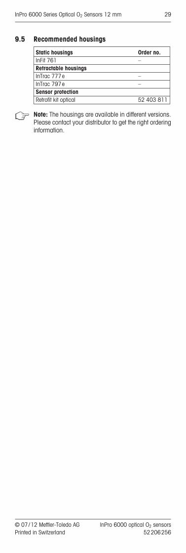
9.5 Recommended housings
Note: The housings are available in different versions.Please contact your distributor to get the right orderinginformation.
Static housings Order no.InFit 761 –Retractable housingsInTrac 777 e –InTrac 797 e –Sensor protectionRetrofit kit optical 52 403 811
© 07 / 12 Mettler-Toledo AG InPro 6000 optical O2 sensors Printed in Switzerland 52 206 256
InPro 6000 Series Optical O2 Sensors 12 mm 29

10 Theory of the optical oxygen measurement
10.1 Introduction
Optical oxygen measurement is a non-invasive method.No electrochemical reaction occurs during measure-ment.
10.2 Principle
In contrast to the aperometric and potentiometric method the optical measurement is not based on achemical reaction and current measurement.
A chromophore in the Sensor is illuminated with bluelight. The chromophore absorbs this energy and istransferred to a higher energy level. A part of the ener-gy is transferred as heat. After a short time the chro-mophore emits a red fluorescence light and returns toits ground state.
If an oxygen molecule collides with the chromophorein its excited state, the energy can be transferred to oxy-gen (Dynamic Quenching). In this case, no fluores-cence light is emitted. Oxygen itself can transfer this en-ergy as heat without light emission.
The emission of fluorescence light is therefore depen-dent on the oxygen partial pressure at the chromo -phore layer.
The emission of fluorescence shows a short time de-lay to the excitation. This time delay can be measure,if the excitation light is being modulated. In this case,the fluorescence shows the same modulation.
The phase shift between excitation and fluorescencedecreases with increasing oxygen concentration.
The oxygen concentration is calculated and digitallytransfered to the transmitter.
10.3 Principle of the design of the optical oxygensensor
10.4 Temperature
Optical FilterReference
LEDDetectorExcitation
LED
Fiber optic
Temperaturesensor
Cap-sleeve
O-RingOpto-layer withchromophor
Metal body
Glass
Optical isolation(black silicone)
Sensor head
Sensor shaft
OptoCap
InPro 6000 optical O2 sensors © 07 / 12 Mettler-Toledo AG52 206 256 Printed in Switzerland
30 InPro 6000 Series Optical O2 Sensors 12 mm

Notes:
© 07 / 12 Mettler-Toledo AG InPro 6000 optical O2 sensors Printed in Switzerland 52 206 256
InPro 6000 Series Optical O2 Sensors 12 mm 31
InPro®6000 SerieOptische O2-Sensoren
Bedienungsanleitung
© 07 / 12 Mettler-Toledo AG InPro 6000 optical O2 sensors Printed in Switzerland 52 206 256
InPro 6000 Series Optical O2 Sensors 12 mm 33
1 Einleitung......................................................................35
2 Wichtige Hinweise.........................................................362.1 Hinweise zur Bedienungsanleitung....................................362.2 Bestimmungsgemässe Verwendung..................................362.3 Sicherheitshinweise.........................................................372.4 Einige typische Applikationsbeispiele.................................38
3 Produktbeschreibung .....................................................393.1 Allgemein.......................................................................393.2 Grundprinzip ..................................................................393.3 Lieferumfang ..................................................................403.4 Ausstattungsmerkmale ....................................................40
4 Installation....................................................................424.1 Einbau des Sensors ........................................................424.1.1 Retrofit-Kit ......................................................................424.2 Sensor anschliessen .......................................................424.2.1 Anschliessen des optischen Sensors an ein Kabel ..............424.2.2 Anschluss des Kabels an den Transmitter ..........................434.2.3 InPro 6860i an einen Analogeingang (nA) anschliessen.....43
5 Betrieb..........................................................................455.1 Inbetriebnahme...............................................................455.2 Konfiguration..................................................................455.2.1 Sensor-Erkennung...........................................................455.2.2 Messrate........................................................................455.2.3 LED-Modus ....................................................................455.3 Kalibrierung ...................................................................465.3.1 Zweck der Kalibrierung ....................................................465.3.2 Werkskalibrierung ...........................................................485.3.3 Einpunktkalibrierung (Steigung und Prozesskalibrierung) ....485.3.4 Steigungskalibrierung ......................................................485.3.5 Prozesskalibrierung.........................................................495.3.6 Zweipunktkalibrierung......................................................505.3.7 Kalibrierung bei Anschluss an Analogausgang ...................505.3.8 Reset auf werksseitige Kalibrierung ...................................505.4 Autoklavieren des InPro 6880i-Sensorschafts ....................51
6 Wartung ........................................................................526.1 Kontrolle des Sensors......................................................526.1.1 Visuelle Kontrolle ............................................................526.1.2 Kontrolle des Sensors mit dem Transmitter.........................526.1.3 ISM ..............................................................................536.2 Austauschen des OptoCap ...............................................54
7 Lagerung.......................................................................56
8 Produktspezifikationen...................................................578.1 Zertifikate .......................................................................578.2 Technische Daten ...........................................................58
9 Bestellinformationen......................................................599.1 Sensoren .......................................................................599.2 Zubehör .........................................................................599.3 Ersatzteile ......................................................................609.4 Empfohlene Transmitter ...................................................609.5 Empfohlene Armaturen ....................................................61
10 Theorie der optischen Sauerstoffmessung .......................6210.1 Einführung .....................................................................6210.2 Grundprinzip ..................................................................6210.3 Prinzipieller Aufbau optischer Sauerstoffsensoren................6210.4 Temperatur.....................................................................6310.5 Strömungsabhängigkeit ...................................................6310.6 Sauerstoffpartialdruck – Sauerstoffkonzentration .................63
Inhalt
InPro 6000 optical O2 sensors © 07 / 12 Mettler-Toledo AG52 206 256 Printed in Switzerland
34 InPro 6000 Series Optical O2 Sensors 12 mm

1 Einleitung
Wir danken Ihnen, dass Sie einen optischen Sauer-stoffsensor von METTLER TOLEDO erworben haben.
Die Bauweise von INGOLDs optischen Sauerstoffsen-soren entspricht dem heutigen Stand der Technik undden zur Zeit anerkannten sicherheitstechnischen Re-geln. Dennoch können bei unsachgemässer Anwen-dung Gefahren für den Anwender oder Dritte und/oderBeeinträchtigungen der Anlage und anderer Sach wer-te entstehen.
Die vorliegende Bedienungsanleitung muss deshalbvor Beginn von Arbeiten an den Sensoren von denbetreffenden Personen gelesen und verstanden wer-den.
Bitte bewahren Sie die Bedienungsanleitung an einemsicheren Ort auf, wo sie für jeden Anwender jederzeitzur Hand ist.
Wenn Sie Fragen haben, die in dieser Bedienungs -anleitung nicht oder nicht ausreichend beantwortet wer den, nehmen Sie bitte mit Ihrem METTLER TOLEDOVertreter Kontakt auf. Man wird Ihnen gerne weiter -helfen.
© 07 / 12 Mettler-Toledo AG InPro 6000 optical O2 sensors Printed in Switzerland 52 206 256
InPro 6000 Series Optical O2 Sensors 12 mm 35

2 Wichtige Hinweise
2.1 Hinweise zur Bedienungsanleitung
Die vorliegende Bedienungsanleitung enthält alle Anga-ben, um den optischen Sensor si cher, sach gerecht undbestimmungsgemäss ein zu setzen.Die Bedienungsanleitung richtet sich an das mit der Bedienung und der Instandhaltung der Sensoren betrau-te Personal. Es wird vorausgesetzt, dass diese Per -sonen Kennt nisse der Anlage besitzen, in der die Sen -soren eingebaut sind.
Warnhinweise und SymboleIn dieser Bedienungsanleitung werden Sicherheitshin-weise und Zusatzinformationen mit folgenden Pikto-grammen gekennzeichnet:
Dieses Piktogramm kennzeichnet Sicherheits- undGefahrenhinweise, deren Missachtung zu Personenund/oder Sachschäden führen können.
Dieses Piktogramm kennzeichnet Zusatzinformatio-nen und Anweisungen, deren Missachtung zu Defek-ten, ineffizienten Betrieb oder zum Ausfall der Produk-tion führen können.
2.2 Bestimmungsgemässe Verwendung
Die optischen Sauerstoffsensoren (InPro 6870i/6880i/6960i und 6970I) dienen zur In-line-Messungdes Sauerstoffpartialdrucks gemäss den Angaben indieser Bedienungsanleitung.
Eine andere oder darüber hinausgehende Benutzung,als in dieser Bedienungsanleitung beschrieben, gilt alsnicht bestimmungsgemäss. Für hieraus resultierendeSchäden haftet der Hersteller/Lieferant nicht. Das Risikoträgt allein der Anwender.
Zur bestimmungsgemässen Verwendung gehören desWeiteren:
– Die Beachtung der Anweisungen, Vorschriften undHinweise in der vorliegenden Bedienungsanleitung.
– Die regelmässige, Inspektion, Wartung und Funktionsprüfung der eingesetzten Komponentenliegt in der Verantwortung des Anwenders. Die loka-len Vorschriften zur Arbeits- und Anlagensicherheitsind zu beachten und einzuhalten.
– Einhaltung aller Hinweise und Warnvermerke inden Publikationen zu den Produkten, die zu -sammen mit dem Sensor verwendet werden (Armaturen, Transmitter etc.).
– Einhaltung aller Sicherheitsvorschriften der Anlage,in die der Sensor eingebaut wird.
InPro 6000 optical O2 sensors © 07 / 12 Mettler-Toledo AG52 206 256 Printed in Switzerland
36 InPro 6000 Series Optical O2 Sensors 12 mm
– Der korrekte Betrieb unter Beachtung der vor -geschriebenen Umwelt- und Betriebsbedingungenund den zulässigen Einbaulagen.
– Bei Unklarheiten soll unbedingt Rücksprache mitMettler-Toledo Prozessanalytik genommen werden.
2.3 Sicherheitshinweise
– Der Anlagenbetreiber muss sich eventueller Risikenund Gefahren seines Prozesses bzw. An lage be-wusst sein. Der Anlagenbetreiber ist ver antwortlichfür die Ausbildung des Betriebspersonals, für dieKennzeichnung möglicher Gefahren und für dieAuswahl geeigneter Instrumentierung anhand desStands der Technik.
– Betriebspersonal, welches an der Inbetriebsetzung,Bedienung oder Wartung dieses Sensors oder einesseiner Zusatzprodukte (Armaturen, Transmitter, etc.)beteiligt ist, muss zwingend in den Pro duktions -prozess und die Produkte eingewiesen sein. Dazu ge-hört auch das Lesen und Verstehen dieser Betriebs-anleitung.
– Die Sicherheit von Betriebspersonal und Anlagenliegt letztendlich in der Verantwortung des Anlagen-betreibers. Dies gilt insbesondere für Anlagen inexplo sions gefährdeten Bereichen.
– Der eingesetzte Sauerstoffsensor und zugehörigeKomponenten haben keinen Einfluss auf den Prozess und können diesen nicht im Sinne einerRegelung oder Steuerung beeinflussen.
– Wartungs- und Serviceintervalle hängen von denEinsatzbedingungen, der umge benen Substanzen,der Anlage und der Sicherheitsrelevanz des Messsystems ab. Kunden prozesse variieren stark,so dass An gaben, soweit diese vorgegeben sind,nur als Richtwerte dienen und in jedem Fall durchden Anlagenbetreiber verifiziert werden müssen.
– Werden bestimmte Schutzmassnahmen wieSchlösser, Beschriftungen oder redundante Mess -systeme gefordert, müssen diese vom Anlagen -betreiber vorgesehen werden.
– Ein defekter Sensor darf weder montiert noch in Betrieb genommen werden.
– Am Sensor dürfen nur Wartungsarbeiten durch -geführt werden, die in dieser Bedienungsanleitungbeschrieben sind.
– Verwenden Sie für den Austausch von defektenKomponenten ausschliesslich METTLER TOLEDOOriginalersatzteile (siehe «Kapitel 9.3, Ersatz teile»).
– An den Sensoren und den Zubehörteilen dürfen keine Änderungen vorgenommen werden. FürSchäden aufgrund von unerlaubten Änderungenhaftet der Hersteller /Lieferant nicht. Das Risiko trägtallein der Anwender.
© 07 / 12 Mettler-Toledo AG InPro 6000 optical O2 sensors Printed in Switzerland 52 206 256
InPro 6000 Series Optical O2 Sensors 12 mm 37

2.4 Einige typische Applikationsbeispiele
Die folgende Aufzählung zeigt einige typische, nicht abschliessende, Applikationsbeispiele für den Einsatzdes Sauerstoffsensors.
Messung in Flüssigkeiten:– Fermentation– Biotechnologie– Nahrungsmittel- und Brauindustrie
InPro 6000 optical O2 sensors © 07 / 12 Mettler-Toledo AG52 206 256 Printed in Switzerland
38 InPro 6000 Series Optical O2 Sensors 12 mm

3 Produktbeschreibung
3.1 Allgemein
Die optischen Sauerstoffsensoren mit integriertemTemperaturfühler werden zur Messung von Sauerstoffverwendet.Er kann sterilisiert werden und ist kompatibel mitCIP-Systemen (Cleaning In Place = Reinigung im ein -ge-bauten Zustand). Die Sensoren InPro 6880i und InPro 6860i sind autoklavierbar (siehe Kapitel 5.4,Seite 47).
3.2 Grundprinzip
Die Funktionsweise der optischen Sauerstoffsensoren be-ruht auf einer Methode der optischen Erkennung, der sogenannten Fluoreszenzlöschung. Hier eine kurze Zusam-menfassung des Prinzips:Im Gegensatz zur polarografischen Clark-Elektrode,die eine Reduktions-Oxidations-Reaktion mit Sauer-stoff an der Elektrode erkennt, basiert die neue optischeMethode auf der Übertragung von Energie zwischenChromophor und Sauerstoff.
– Ein Chromophor in der Sensorspitze wird mit blau-em Licht angestrahlt. Dieses Chromophor nimmtdie Energie auf und emittiert, wenn kein Sauerstoffpräsent ist, nach einer bestimmten Zeitverzögerungund für eine bestimmte Dauer rotes Fluoreszenz-licht. Das emittierte Licht wird vom Detektor im Sen-sorkopf erkannt.
– Wenn Sauerstoff vorhanden ist, überträgt das Chromophor die Energie auf das Sauerstoffmolekül.Das Sauerstoffmolekül gibt diese Energie dann alsWärme an die Umgebung ab, und es findet keineFluoreszenz statt.
– Gesamtintensität und Dauer der Fluoreszenz sindvom Sauerstoffpartialdruck im Medium abhängig.
– Zur Analyse der Fluoreszenzdauer wird das Anre-gungslicht mit einer konstanten Frequenz getaktet,das emittierte Licht weist den selben Verlauf, jedochmit einer zeitlichen Verzögerung im Vergleich zumAnregungslicht auf. Diese Zeitverzögerung wird alsPhasenverschiebung oder Phasenwinkel (Phi) be-zeichnet. Die Phasenverschiebung ist vom Sauer-stoffgehalt abhängig und folgt der Stern-Vollmer-Gleichung.
– Der Sensor erkennt diese Phasenverschiebung undberechnet die Sauerstoffkonzentration.
– Der Sauerstoffwert wird in digitaler Form an denTransmitter übertragen.
© 07 / 12 Mettler-Toledo AG InPro 6000 optical O2 sensors Printed in Switzerland 52 206 256
InPro 6000 Series Optical O2 Sensors 12 mm 39
3.3 Lieferumfang
Jeder Sensor wird vollständig zusammengesetzt undnach werkseitiger Testung sowie Kalibrierung zur Über-prüfung des ordnungsgemässen Funktionierens mitfolgender Komponente geliefert:– einem Qualitäts-Kontrollzertifikat– Materialzertifikaten 3.1
(entsprechend EN10204.3/1.B)– Wartungskappe (nicht für InPro 6860i)
Wichtig! Jeder Sensor ist werkseitig kalibriert. Die Da-ten sind im Sensorkopf gespeichert. Wenn mehrereSensoren des Typs InPro 6880i verwendet werden,müssen Sie daher immer darauf achten, dass Sensor-kopf und Sensorschacht nicht vertauscht werden. An-derenfalls muss der Sensor erneut kalibriert werden, dadie Kalibrationsdaten des Werks nicht mehr korrektsind.
3.4 Ausstattungsmerkmale
Zwei verschiedene Typen von optischen Sensoren fürFermentationen sind verfügbar.
InPro 6880i und InPro 6860i eignen sich für Anwen-dungen, in denen autoklaviert wird. Beim InPro 6880ikann der Sensorkopf abgenommen werden, sodassnur der Schaft den hohen Temperaturen ausgesetzt ist.Bleibt der Sensorkopf während des Autoklavierens mitdem Schaft verbunden, kann die Elektronik zerstörtwerden. Der InPro 6860i ist vollständig autoklavierbar.
Der InPro 6870i ist vorgesehen für den Gebrauch ingrösseren Fermentern, wo nur sterilisiert wird. Hier wirdder Sensorkopf nicht den hohen Temperaturen ausge-setzt.
Der InPro InPro 6960i /6970i ist vorgesehen für dieBenutzung in der Nahrungsmittel- und Brauindustriezur Messung von hohen und niedrigen O2-Konzentra-tionen im ppb-Bereich.
InPro 6000 optical O2 sensors © 07 / 12 Mettler-Toledo AG52 206 256 Printed in Switzerland
40 InPro 6000 Series Optical O2 Sensors 12 mm
a
5-Pin-Stecker
Sensorkopf
GewindehülsePg 13.5
GleitscheibeO-Ring
Sensorschaft
[ 12 mm
Innenkörper
O-Ring
OptoCap
O-RingO-Ring
Schafthülse
InPro 6870 iInPro 6960 iInPro 6970 i:Der Sensor-kopf kannnicht vomSensorschaftgetrennt wer-den.
InPro 6880 i
VP Stecker
Sensorkopf
GewindehülsePg 13.5
Gleitscheibe
O-Ring
Sensorschaft
[ 12 mm
optisches Modul
O-Ring
OptoCap
a
InPro 6860 i
© 07 / 12 Mettler-Toledo AG InPro 6000 optical O2 sensors Printed in Switzerland 52 206 256
InPro 6000 Series Optical O2 Sensors 12 mm 41
4 Installation
Dank des «Plug & Measure»-Konzepts kann der Benut-zer das Gerät unmittelbar nach der Installation zur Sauer -stoffmessung nutzen.
– Der Sensor /die Sensorbox wird automatisch er-kannt, alle wichtigen Daten werden zum Transmit-ter gesendet und die Sauerstoffwerte angezeigt. Der Sensor ist werkseitig kalibriert. Die Kalibrations-daten des Werks sind im Sensor gespeichert undmüssen nicht vom Benutzer eingegeben werden.
4.1 Einbau des Sensors
Wichtig! Nehmen Sie vor der Montage des Sensors dieSchutzkappe ab .
Einbau des Sensors in eine ArmaturFür den Einbau des Sensors in eine Armatur beachtenSie bitte Angaben in der entsprechenden Anleitung zurArmatur.
Direkter Einbau der Sensoren in ein Rohr /Kessel Die 12 mm O2-Sensoren können direkt in einen Ge -win destutzen Pg 13,5 eingeschraubt und mit der Ge -win dehülse Pg 13,5 festgezogen werden. Der Sensorkann in jeder beliebigen Orientierung installiert werden.
Achtung! Sensor nicht gegen den Uhrzeigersinn dre-hen, solange er in einer Armatur installiert ist, da sichdadurch die Schafthülse lösen könnte.
4.1.1 Retrofit-Kit
Um den Sensor vor Umwelteinflüssen (Temperatur,Luftfeuchtigkeit) zu schützen, empfehlen wir den Ge-brauch des Retrofit-Kit (52 403 811). Für die Installa-tion beachten Sie bitte die Bedienungsanleitung desRetrofit-Kit.
Retrofit-Kit
4.2 Sensor anschliessen
4.2.1 Anschliessen des optischen Sensors an ein Kabel
Der Sensor ist mit dem Transmitter über ein 5-poligesDatenkabel für die Sensoren InPro 6870 i, 6880 i,6960i und 6970i oder ein VP6/VP8 Kabel für den InPro 6860i verbunden. Mit dem Datenkabel wird ei-ne sichere Verbindung zwischen dem Transmitter unddem Sensor auch unter rauen Industriebedingungen si-chergestellt. Das robuste, wasserdichte IP67-Stecker-gehäuse gewährleistet grösstmögliche Prozesssicher-heit. Zum Anschliessen des Datenkabels an den Sensorrichten Sie den Schlitz des Anschlusses auf den Stift desSteckers aus. Dann schrauben Sie den Stecker fest, umdie beiden Teile fest miteinander zu verbinden.
InPro 6000 optical O2 sensors © 07 / 12 Mettler-Toledo AG52 206 256 Printed in Switzerland
42 InPro 6000 Series Optical O2 Sensors 12 mm

4.2.2 Anschluss des Kabels an den Transmitter
Transmitter M400
Hinweis: Eine Übersicht über die Kabelbelegung findenSie in der Kabelbedienungsanleitung von METTLER TOLEDO.
Hinweis: Informationen zum Anschliessen von Kabelnan die Anschlüsse des Transmitters finden Sie in derTransmitterbedienungsanleitung von METTLER TOLEDO.
Das Kabel ist in verschiedenen Längen bei METTLERTOLEDO erhältlich:
Schliessen Sie das Datenkabel wie in der Tabelle un-ten beschrieben an den Transmitter an.
* gilt nur für VP8
4.2.3 InPro 6860i an einen Analogeingang (nA) an-schliessen
Der InPro 6860i übermittelt den Sauerstoffwert als nA-Signal und den Temperaturwert als NTC 22K�-Signalan den Biocontroller oder einen analogen Transmitter.In dieser Situation verhält sich der Sensor wie ein ana-loger amperometrischer Sensor (InPro 6800).
Schliessen Sie das Datenkabel am Transmitter an, wiein der Tabelle beschrieben.
VP-Verbindung an einen digitalen EingangVP-Kabel VP8
M400 M800K-2 K-4
Farbe Funktion TB4 TB2 TB4A schwarz/transp. Kathode (nA)B rot Anode (nA)C grau 24DC + 1 9 9D blau 24DC – 2 10 10E weiss NTC 22k�F grün NTC 22k�(GND)G* pink RS485 + 8 14 14H* braun RS485 – 7 13 13S grün/gelb Shield 4 12 12
RS485-Kabel InPro 6870i/6880i/6960i/6970iM400 M800
Kanal 2 Kanal 4Farbe Funktion TB4 TB2 TB4braun 24DC + 1 9 9schwarz 24DC – 2 10 10grau Shield 6 12 12gelb Shield 6 15 15blau RS485 – 7 13 13weiss RS485 + 8 14 14
© 07 / 12 Mettler-Toledo AG InPro 6000 optical O2 sensors Printed in Switzerland 52 206 256
InPro 6000 Series Optical O2 Sensors 12 mm 43

* gilt nur für VP8
VP-Verbindung an einen analogen EingangVP-Kabel VP8 oder VP6Farbe Funktion analog/nA
A schwarz/transp. Kathode (nA) KathodeB rot Anode (nA) AnodeC grau Sensor + 24V DC +D blau Sensor – 24V DC –E weiss NTC 22k� NTC 22k�F grün NTC 22k�(GND) NTC 22k�(GND)G* pink RS485 +H* braun RS485 –S grün/gelb Shield Shield
InPro 6000 optical O2 sensors © 07 / 12 Mettler-Toledo AG52 206 256 Printed in Switzerland
44 InPro 6000 Series Optical O2 Sensors 12 mm
5 Betrieb
5.1 Inbetriebnahme
Jeder Sensor wird in einsatzbereitem Zustand geliefert.Nehmen Sie vor der Inbetriebnahme die Schutzkappeab.
HInweis: Polarisierung und Kalibrierung sind nicht er-forderlich. «Plug & Measure»-Konzept.
5.2 Konfiguration
5.2.1 Sensor-Erkennung
Bevor Sie einen optischen Sensor installieren, schlagenSie im Handbuch für den Transmitter nach und konfi-gurieren Sie den Transmitter für die automatische Sen-sorerkennung. Der Transmitter M800 benötigt keiner-lei Vorkonfiguration.
5.2.2 Messrate
Optische Sauerstoffsensoren führen keine permanentenMessungen durch. Jeder Messzyklus dauert etwa 1 Se-kunde. Um die Lebensdauer der OptoCap zu verlän-gern, lässt sich das Messintervall auf einen beliebigenWert zwischen 1 und 60 Sekunden einstellen. WählenSie die passende Einstellung.
Voreingestellt sind 10 Sekunden, was für die meistenAnwendungen ausreicht.
5.2.3 LED-Modus
Ein Faktor für die Alterung des OptoCaps ist die Mes-sung selbst. Um die Lebensdauer des OptoCaps zu ver-längern, kann das System ausgeschaltet werden so-bald es nicht gebraucht wird. Insbesondere währendder CIP-Zyklen oder wenn sich die Anlage im Standbybefindet und der Sensor hohen Sauerstoffkonzentratio-nen ausgesetzt ist, sollten keine Messungen erfolgen.Messungen während der CIP-Zyklen können einen star-ken Sensordrift zur Folge haben.
Sobald die LED ausgeschaltet ist, sendet der Sensor einkonstantes Signal von –1% Luft an den Transmitter.Der Transmitter wird in den «Hold-Modus» geschaltet.Um den «Hold-Modus» zu konfigurieren, benutzen Siebitte die Bedienungsanleitung des Transmitters.
Automatische LED-Abschaltung bei hohen Tempera-turenIst der LED-Modus auf «Auto» (Standardeinstellung)gesetzt, wird die LED abgeschaltet, sobald eine spezi-fische Temperatur erreicht wird. Die Standardeinstellun-gen sind unterschiedlich für die verschiedenen opti-schen Sensoren.
© 07 / 12 Mettler-Toledo AG InPro 6000 optical O2 sensors Printed in Switzerland 52 206 256
InPro 6000 Series Optical O2 Sensors 12 mm 45

Diese Limite können individuell durch den Benutzer ein-gestellt werden. Dazu Transmitter (M400 oder M800)oder iSense verwenden. Diese Einstellungen sind auchaktiv, wenn der Sensor über den Analoganschluss (nA)mit dem Prozess verbunden ist. Die Abschalttempera-tur sollte mindestens 5°C höher eingestellt werden, alsdie Höchst-Prozesstemperatur. Wenn z.B. die Prozess-temperatur bei 37°C liegt, sollte die Abschalttempera-tur auf 42°C eingestellt werden. Sobald die Temperaturvon 42°C erreicht wird, wird die LED abgeschaltet. ZurAnschaltung der LED wurde eine Hysterese von 3°Ceingestellt, dies bedeutet, dass die LED angeschaltetwird, sobald die Temperatur unter 39°C fällt.
Manuelle LED-Abschaltung(Transmitter M400 / M800)Die LED des Sensors kann manuell über den Trans-mitter abgeschaltet werden, indem der LED-Modusauf «off» gesetzt wird. (siehe Transmitter-Bedie-nungsanleitung). Um die Messung wieder zu starten,muss die LED wieder manuell oder über ein digitalesEingangssignal eingeschaltet werden.
Abschaltung der LED durch ein externes Signal(Transmitter M400 / M800)Der Transmitter M400 kann über ein externes Signalin den «Hold-Modus» versetzt werden. In dieser Si-tuation wird die LED des Sensors ausgeschaltet. So-bald der «Hold-Modus» aufgehoben wird, beginnt deroptische Sensor wieder mit der Messung mit den vor-herigen Einstellungen.
5.3 Kalibrierung
5.3.1 Zweck der Kalibrierung
Informationen zur Kalibrierung finden Sie ebenfalls imTransmitterhandbuch.
Die Kalibrierung muss nach jedem Austausch der Op-toCap, nach jeder Sterilisation oder nach dem Autokla-vieren des Sensors erfolgen.
Da der Zusammenhang zwischen gemessener Phaseund Sauerstoffkonzentration nicht linear ist, muss eineKalibrierung des optischen Sensors sehr genau durch-geführt werden. Fehlerhafte Kalibrierungen können dieMessgenauigkeit des Sensors deutlich reduzieren undverursachen eine falsche Berechnung des DLI (Dyna-mic Lifetime Indicator) und des ACT (Adaptive Calibra-tion Timer).
TemperaturenHöchst-Prozess- voreing. Ab- temperatur schalttemperatur
InPro 6860i 60°C 60°CInPro 6870i 60°C 60°CInPro 6880i 60°C 60°CInPro 6960i 40°C 40°CInPro 6970i 40°C 40°C
InPro 6000 optical O2 sensors © 07 / 12 Mettler-Toledo AG52 206 256 Printed in Switzerland
46 InPro 6000 Series Optical O2 Sensors 12 mm

Jeder Sensor hat seinen eigenen Phasenwinkel beiNull Sauerstoff (phi 0) und einhundert Prozent Luftsät-tigung (phi 100). Beide Werte verändern sich, etwanach dem Auswechseln der OptoCap oder einfachdurch natürliche Alterung der OptoCap.
Abhängig vom verwendeten optischen Sensortyp ste-hen unterschiedliche Kalibriermethoden zur Verfügung.Die höchste Messgenauigkeit erreicht man durch eine2-Punkt-Kalibrierung mit Luft und einem Nullpunktgas,z.B.N2 oder CO2 mit einer Reinheit von mindestens99,9%. Für den InPro 6970i ist eine Reinheit von99,99% erforderlich.
KalibrierungsartSensortyp 1-Punkt (Luft) 2-Punkt ProzessInPro 6860i • • •InPro 6870i • • •InPro 6880i • • •InPro 6960i • • •InPro 6970i – • •
Eine 1-Punkt Nullpunktkalibrierung ist im Gegensatzzum amperometrischen Sensor nicht ausreichend, umeine hohe Messgenauigkeit über den gesamten Mess-bereich zu erreichen und wird aus diesem Grunde nichtangeboten (nur InPro 6970i).
Eine Kalibrierung des optischen Sensors muss miteinem digitalen Transmitter oder iSense erfolgen.
Hinweis: Um zu prüfen, ob der Sensor kalibriert wer-den muss, trocknen Sie den Sensor ab und haltenSie ihn in die Luft. Der Transmitter sollte jetzt einenWert von nahezu 100% anzeigen. Ist dies nicht derFall, muss der Sensor nachkalibriert werden. Beach-ten Sie bitte auch den korrekten Luftdruck und dieFeuchtigkeit. Geringe Abweichungen an der Luft(�3%) gehen zurück auf unterschiedliche Luft-feuchtigkeit und Einstellungen des Prozessdrucks.Der Sensor rechnet mit 100% Luftfeuchtigkeit,wenn er auf die Messung von gelöstem Sauerstoffeingestellt ist.
Generelle Bemerkungen:
– Für die Gas-Kalibrierung an Luft muss das Opto-Cap des Sensors trocken sein, da anhaftendeWassertropfen den Sauerstoffmesswert verfäl-schen.
– Vergewissern Sie sich, dass die Einstellungen fürdie Sauerstoffsättigung bei der Kalibrierung kor-rekt sind und während der Kalibrierung konstantbleiben.
– Falls die Kalibrierung in Wasser oder Messmediumerfolgt, muss sich das Kalibriermedium mit Luftim Gleichgewichtszustand befinden. Der Sauer-stoffaustausch zwischen Wasser und Luft läuft nursehr langsam ab. Es dauert daher relativ lange, bisWasser mit Luft gesättigt ist.
© 07 / 12 Mettler-Toledo AG InPro 6000 optical O2 sensors Printed in Switzerland 52 206 256
InPro 6000 Series Optical O2 Sensors 12 mm 47

48 InPro 6000 Series Optical O2 Sensors 12 mm
InPro 6000 optical O2 sensors © 07 / 12 Mettler-Toledo AG52 206 256 Printed in Switzerland
– Die Kalibrierung in einem Fermenter muss nachder Sterilisation als Prozesskalibrierung erfol-gen (siehe Abschnitt 5.3.5).
– Achten Sie darauf, dass alle anderen Parameterwie Temperatur und Druck, während der Kalibrie-rung konstant bleiben.
– Kalibrierung setzt immer eine genaue Druck- undTemperaturmessung voraus. Nur die Prozessska-lierung bleibt von diesen Parametern unbeeinflusst(siehe Abschnitt 5.3.5).
– Stellen Sie sicher, dass der korrekte Kalibrierdruck,Luftfeuchtigkeit und Salzgehalt im Transmitter ein-gestellt sind, bevor die Kalibrierung gestartet wird.
– Bitte beachten Sie auch die Bedienungsanleitungdes Transmitters für detailierte Informationen.
5.3.2 Werkskalibrierung
Der Sensor wird vorkalibriert und einsatzbereit geliefert.Informationen zur Aktivierung dieser Kalibrierung findenSie im Transmitterhandbuch.
Die Daten der Werkskalibrierung sind im Sensor gespei-chert und können vom Benutzer nicht geändert werden.Während dieser Kalibrierung werden alle sensorspezi-fischen Parameter bestimmt.
Bei Dauerbetrieb empfehlen wir eine periodischeNachkalibrierung entsprechend der gewünschten Ge-nauigkeit, der Art des Prozesses und Ihrer Erfahrung.Die Häufigkeit der notwendigen Nachkalibrierung iststark applikationsspezifisch und kann daher an dieserStelle nicht genau definiert werden.
5.3.3 Einpunktkalibrierung (Steigung und Prozesskali-brierung)
Für die meisten Applikationen ist eine Einpunktkalibrie-rung ausreichend, solange nicht der gesamte Messbe-reich benötigt wird.
Während einer Einpunktkalibrierung wird der Phasen-winkel des Nullpunktes oder bei Luft bestimmt. Der da-zugehörige zweite Wert wird berechnet.
5.3.4 Steigungskalibrierung (InPro 6870i, InPro 6880iund InPro 6960i)
In den meisten Applikationen, bei denen Sauerstoffkon-zentrationen zwischen 10% und 200% Luftsättigunggemessen werden ist eine Einpunktkalibrierung ausrei-chend, um die geforderte Genauigkeit zu erreichen.
Das Kalibriermedium kann entweder Luft oder ein Ka-libriergas mit bekannter Sauerstoffkonzentration oderWasser mit einer bekannten Sauerstoffkonzentrationsein.
Bevor die Kalibrierung in Gas gestartet wird, muss derkorrekte Druck und die Luftfeuchtigkeit im Transmittereingegeben werden.
Hinweis: Falsche Druckwerte sind die häufigste Ur-sache für ungenügende Messgenauigkeit.
So führt z. B. eine Differenz von 50mbar zwischen demUmgebungsdruck und dem eingestellten Wert imTransmitter zu einem Messfehler von 5%.
Bei einer Kalibrierung in Gas ist es wichtig, dass dieTemperaturmessung des Sensors stabil ist und diewirkliche Gastemperatur angezeigt wird.
Nachdem sich das Sensorsignal stabilisiert hat kanndas komplette Messsystem auf den 100%-Wert dergewählten Messgrösse kalibriert werden z.B. 100%Luft, 20,96% O2 oder 8,26ppm bei 25°C und Nor-maldruck (siehe auch die Bedienungsanleitung desTransmitters)
5.3.5 Prozesskalibrierung
Eine Prozesskalibrierung wird in Situationen benötigt,wo der Sensor nicht aus dem Prozess entfernt werdenkann.
Für detaillierte Informationen beachten Sie bitte auchdie Bedienungsanleitung des Transmitters.
Für die Prozesskalibrierung sind zwei verschiedeneRoutinen möglich:
– Prozesskalibrierung
– Prozessskalierung
Prozesskalibrierung erfolgt, wenn ein zuverlässigerKontrollwert verfügbar und der Prozessdruck bekanntist. Der Prozessdruck wird nur dann benötigt, wenn dasSystem in Sättigungswerten (%-Luft oder %-O2) oderGaseinheiten (ppm Gas) misst. Während dieser Kali-brierung werden die Phasenwerte der Eichkurve ange-passt.
Prozessskalierung erfolgt vor allem in Biopharma-An-wendungen nach der Sterilisation (Autoklavieren),wenn der Anwender die Entscheidung trifft, das Systemauf einen Ausgangswert einzustellen. Während dieserKalibrierung werden die Phasenwerte des Sensorsnicht eingestellt, lediglich die angezeigten Werte unddie nA-Ausgänge werden auf die gewünschten Werteneu skaliert.
Hinweis: Für eine Prozesskalibrierung kann der Benut-zer entscheiden, ob der Prozessdruck oder der Kali-brierdruck verwendet wird. Dies hängt von der Metho-de ab, wie der Referenzwert ermittelt wurde.
Nachdem sich das Sensorsignal stabilisiert hat, kanndas komplette Messsystem auf die gewählte Messgrös-se kalibriert werden z.B. Luft, O2 oder ppm bei 25°C(siehe auch die Bedienungsanleitung des Transmit-ters).
Hinweis: Für diesen Kalibriertyp sind eine genaueReferenzmessung und korrekte Druckeinstellungenessentiell.
InPro 6000 Series Optical O2 Sensors 12 mm 49
© 07 / 12 Mettler-Toledo AG InPro 6000 optical O2 sensors Printed in Switzerland 52 206 256
5.3.6 Zweipunktkalibrierung
Zur Erzielung einer hohen Messgenauigkeit über denganzen Messbereich ist eine Zweipunktkalibrierung er-forderlich. Ebenso nach jedem Austausch des Opto-Cap.
Bei einer Zweipunktkalibrierung werden beide Phasen-winkel bei null Sauerstoff (phi 0) und 100% Luft(phi 100) bestimmt.
Punkt 1: Steilheitkorrektur (mit Luft oder einem ande-ren Kalibrierungsgas mit bekannter O2-Konzentration)
Nachdem sich das Sensorsignal stabilisiert hat, kanndas komplette Messsystem auf den 100%-Wert dergewählten Messgrösse kalibriert werden z.B. 100%Luft, 20,96% O2 oder 8,26ppm bei 25°C und Nor-maldruck (siehe auch die Bedienungsanleitung desTransmitters).
Punkt 2: Nullpunkt
Nachdem sich das Sensorsignal stabilisiert hat kanndas komplette Messsystem auf den 0%-Wert der ge-wählten Messgrösse kalibriert werden z.B. 0% Luft,0% O2 oder 0ppm bei 25°C (siehe auch die Bedie-nungsanleitung des Transmitters).Hinweis: Eine unkorrekte Nullpunktkalibrierung isteine häufige Fehlerquelle. Für eine korrekte Durch-führung empfehlen wir als Nullpunktmedium Stick-stoff oder ein anderes sauerstofffreies Medium miteinem Reinheitsgrad von mindestens 99,995%.
5.3.7 Kalibrierung bei Anschluss an Analogeingang
Wenn der Sensor an einen Analogeingang angeschlos-sen wird, lässt sich nur der Sensorausgang neu ska-lieren.
Die Abläufe sind die gleichen, wie bei amperometri-schen Sensoren:1. Anpassung der Steigung2. Offset-Anpassung
Diese Verfahren ersetzten keinesfalls die echte Kalibrie-rung eines optischen Sensors.
Bevor der Sensor in einen Fermenter eingebaut wird,muss mit der iSense Asset Suite, iSenseLight oder ei-nem digitalen Transmitter eine Einpunktkalibrierung anLuft erfolgen (siehe Abschnitt 5.3.2).
Eine Zweipunktkalibrierung (siehe 5.3.6) muss nachjedem Austausch der OptoCap erfolgen und, je nachBelastungen im Prozess, alle 5 bis 10 Chargen.
5.3.8 Reset auf werksseitige Kalibrierung
Im Falle einer falschen Kalibrierung des optischen Sen-sors, z.B. bei der Verwendung falscher Werte währendder Steigungs- oder Prozesskalibrierung, muss derSensor vor einer neuen Kalibrierung auf die Werkska-librierungsdaten zurückgesetzt werden.
InPro 6000 optical O2 sensors © 07 / 12 Mettler-Toledo AG52 206 256 Printed in Switzerland
50 InPro 6000 Series Optical O2 Sensors 12 mm
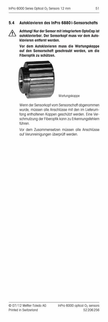
5.4 Autoklavieren des InPro 6880i-Sensorschafts
Achtung! Nur der Sensor mit integriertem OptoCap istautoklavierbar. Der Sensorkopf muss vor dem Auto-klavieren entfernt werden.
Vor dem Autoklavieren muss die Wartungskappe auf den Sensorschaft geschraubt werden, um die Fiberoptik zu schützen.
Wartungskappe
Wenn der Sensorkopf vom Sensorschaft abgenommenwurde, müssen alle Anschlüsse mit den im Lieferum-fang enthaltenen Kappen geschützt werden. Eine Ver-schmutzung der Fiberoptik kann zu Erkennungsfehlernführen.
Vor dem Zusammensetzen müssen alle Anschlüsseauf Verunreinigungen überprüft werden.
© 07 / 12 Mettler-Toledo AG InPro 6000 optical O2 sensors Printed in Switzerland 52 206 256
InPro 6000 Series Optical O2 Sensors 12 mm 51

6 Wartung
Hinweis: Die Wartungsarbeiten können ohne jegli-ches Werkzeug durchgeführt werden.
6.1 Kontrolle des Sensors
6.1.1 Visuelle Kontrolle
Zur Überprüfung des Sensors empfehlen wir folgendeVorgehensweise:
• Die Kontakte am Anschlussstecker müssen trockensein. Feuchtigkeit, Korrosion und Schmutz im An-schlussstecker können zu Fehlanzeigen führen.
• Kabel auf Knickstellen, spröde Stellen oder Brücheüberprüfen.
• Überprüfen Sie das OptoCap vor der Kalibrierungstets auf optisch sichtbare Anzeichen von Beschä-digung. Das OptoCap muss intakt und sauber sein.Sollte die Oberfläche verschmutzt sein, muss siemit einem weichen, feuchten Tuch gereinigt wer -den .
Vorsicht! Verwenden Sie niemals Reinigungsmittel,die Alkohol oder Lösemittel enthalten. Der Sensorkönnte dadurch zerstört werden.
6.1.2 Kontrolle des Sensors mit dem Transmitter
Wenn die gemessenen Werte vom erwarteten Wert abweichen, sollte eine Luftkalibrierung durchgeführtwerden.
Passende Phasenwerte nach einer Kalibrierung:Abhängig vom Alter des OptoCap sinken die Phasenwer-te typischerweise über die Lebensdauer verglichen zuden Werten eines neuen OptoCap ab (siehe Tabelle).Nur für den InPro 6970i steigt die Phase an Luft.
Neues OptoCap Grenzwerte für altes OptoCap
Sensortyp Phi0 Phi100 Phi0 Phi100InPro 6860i 60°±2° 32°±3° <50° <15°InPro 6870i 60°±2° 32°±3° <50° <15°InPro 6880i 60°±2° 32°±3° <50° <15°InPro 6960i 68°±3° 30°±2° <55° <15°InPro 6970i 82°±3° 13°±2° <65° >18°
Das OptoCap muss ausgetauscht werden, sobald dieGrenzwerte erreicht werden.
Die Phasenwerte des Sensors werden in der Kalibrierhis-torie gespeichert. Der aktuelle Phasenwert lässt sich imMenü «Calibration – Verify» oder mit iSense überprüfen.
Wenn nach derartigen Verfahren die genannten Werteimmer noch nicht erreicht werden, ersetzen Sie das OptoCap. Wenn auch durch diese Massnahme dasProblem nicht gelöst werden kann, schicken Sie denSensor zur Überprüfung an den für Sie zuständigen Ver-treter von METTLER TOLEDO.
InPro 6000 optical O2 sensors © 07 / 12 Mettler-Toledo AG52 206 256 Printed in Switzerland
52 InPro 6000 Series Optical O2 Sensors 12 mm

Eine Nullsauerstoffmessung kann mit Hilfe von CO2oder Nitrogen (N2) durchgeführt werden. Alternativ isteine derartige Messung auch in einem Testmedium, dasmit einem der beiden Gase gesättigt ist, möglich.
Nach 2 Minuten in einem sauerstofffreien Mess mediumsollte der Sensor weniger als 5% und nach 10 Minu-ten weniger als 1% des Luftmesswertes liefern.
Sollten die oben erwähnten Werte nicht erreicht werden,ersetzen Sie das OptoCap des Sensors. Hilft auch die-se Massnahme nichts, senden Sie den Sensor zur In-spektion an Ihre METTLER TOLEDO Vertretung.
Viele Testmedien beinhalten flüchtige Substanzen, dieselbst in sehr geringen Konzentrationen einen deutlichfeststellbaren Geruch haben. Ähnlich wie Sauerstoffkönnen diese Substanzen in das OptoCap eindringen.Sie werden sichtbar, wenn es zu Interaktionen mit demPigment kommt. In den meisten Fällen haben derartigeSubstanzen keinen Einfluss auf die Messeigenschaftendes Sensors.
6.1.3 ISM
DLI: Dynamischer Lebenszeit-IndikatorDer DLI gibt Informationen über die verbleibende Lebens-dauer des OptoCap. Solange der DLI nicht abgelaufen ist,misst der Sensor innerhalb der spezifizierten Genauigkeitnach einer Kalibrierung. Sobald der DLI abgelaufen ist,muss das OptoCap ausgetauscht werden.
Faktoren, die die Alterung des OptoCap beeinflussen:• Anzahl der Messungen• Temperatur während der Messung• Sauerstoffkonzentration während der Messung• Anzahl der CIP-Zyklen• Anzahl der SIP-Zyklen• Anzahl der Autoklavierungen
Der DLI wird auf 2 unterschiedliche Methoden berech-net.
Kontinuierlich während der Messung: Mit den obenbeschriebenen Parametern wird der aktuelle Sensor-stress berechnet. Mit jeder Messung wird die Gesamt-belastung erhöht. Die summierte Sensorbelastung ge-teilt durch die abgelaufene Zeit ist die Basis derBerechnung der verbleibenden Lebenszeit.
Während der Kalibrierung: Die Phasenwerte werdenverglichen mit den Phasenwerten der letzten Kalibrie-rung. Zusammen mit der berechneten Gesamtbelas-tung des Sensors und der abgelaufenen Zeit seit derletzten Kalibrierung wird die verbleibende Lebenszeitdes OptoCap berechnet. Die Berechnung nach einerKalibrierung führt zu einer höheren Genauigkeit des DLIverglichen zu der kontinuierlichen Berechnung. DieDLI-Werte können sich dadurch nach einer Kalibrie-rung deutlich verändern.
Hinweis: Für eine korrekte DLI-Berechnung ist eine ak-kurate Kalibrierung erforderlich.
© 07 / 12 Mettler-Toledo AG InPro 6000 optical O2 sensors Printed in Switzerland 52 206 256
InPro 6000 Series Optical O2 Sensors 12 mm 53

ACT: Adaptiver Kalibrier-TimerDer ACT gibt Informationen darüber, wann die nächs-te Kalibrierung notwendig ist, um innerhalb der spezi-fizierten Genauigkeit zu messen. Diese Berechnungbasiert auf den DLI-Informationen. Solange der ACTnicht abgelaufen ist, misst der Sensor innerhalb derspezifizierten Genauigkeit. Der Maximalwert für denACT kann vom Benutzer selbst festgelegt werden.
KalibrierungshistorieDie Daten der letzten vier Kalibrationen und die derWerkskalibration sind im Sensor gespeichert. DieseDaten können mit dem Transmitter oder mit iSenseausgelesen werden. Die Kalibrationshistorie gibt wert-volle Informationen über die Qualität der Kalibrationund über die Alterung des OptoCap.
6.2 Austauschen des OptoCap
Zum Austauschen des OptoCap müssen Sie zunächstdie Überwurfhülse abschrauben.
Achtung!Wenn die Überwurfhülse entfernt ist, müssenSie vorsichtig mit dem Innenteil des Sensorschafts um-gehen. Eine Beschädigung oder Verunreinigung der inneren Teile und der Glasfaserleiter kann das Signalbeeinflussen oder den Sensor zerstören. Kleinere Ver-schmutzungen können mit einem fusselfreien Tuchentfernt werden.
Beim Austauschen des OptoCap müssen die folgendenAnweisungen beachtet werden :
Achtung! Führen Sie die nachfolgenden Arbeitsschrittenur an einem sauberen Arbeitsplatz aus.
Achtung! Beim InPro 6860i sind Schafthülse und Op-toCap ein Teil. Um die OptoCap auszutauschen, mussdie gesamte Einheit ersetzt werden.
1. Überwurfhülse vom Sensorschaft abschrauben undvorsichtig vom Sensor ziehen.
2. OptoCap vom Innenkörper abziehen.
3. Neues OptoCap oben auf dem Innenkörper desSensorschafts platzieren.
4. Überwurfhülse vorsichtig auf das richtig ausgerich-tete OptoCap ziehen und festschrauben. Die Über-wurfhülse muss sauber und trocken sein.
5. Nach jedem Austausch der OptoCap muss der DLImanuell mit einem Transmitter oder iSense zurück-gesetzt werden.
6. Nach jedem Austausch der OptoCap muss der Sen-sor mit einer Zweipunktkalibrierung neu kalibriertwerden.
Achtung! Die Qualität dieser Kalibrierung ist kritischhinsichtlich der Sensorleistung und der Genauigkeitder Diagnose.
InPro 6000 optical O2 sensors © 07 / 12 Mettler-Toledo AG52 206 256 Printed in Switzerland
54 InPro 6000 Series Optical O2 Sensors 12 mm

Austausch der OptoCap
InPro 6870i/6880i/ InPro 6860i6960i/6970i
5 Pin connector
Sensor head
Threaded sleevePg 13.5
WasherO-Ring
Sensorschaft
[ 12 mm
Innenkörper
Temperatur- fühler
O-Ring
OptoCap
O-RingO-Ring
Schafthülse
InPro 6870 iInPro 6960 iInPro 6970 i: The sensor head is not separable from the sensor shaft.
InPro 6880 i
InPro 6860 i
VP connector
Sensor head
Threaded sleevePg 13.5
Washer
O-Ring
Sensorschaft
[ 12 mm
optisches Modul
O-Ring
OptoCap
© 07 / 12 Mettler-Toledo AG InPro 6000 optical O2 sensors Printed in Switzerland 52 206 256
InPro 6000 Series Optical O2 Sensors 12 mm 55

7 Lagerung
Der Sensor sollte zum Lagern sauber und trocken sein.Die Schutzkappen müssen auf den Sensor und die Kabelanschlüsse gesetzt werden. Wenn der Sensor-schaft ohne Sensorkopf aufbewahrt wird, muss dieWartungskappe zum Schutz der Fiberoptik verwendetwerden.
InPro 6000 optical O2 sensors © 07 / 12 Mettler-Toledo AG52 206 256 Printed in Switzerland
56 InPro 6000 Series Optical O2 Sensors 12 mm

8 Produktspezifikationen
8.1 Zertifikate
Jeder Sensor wird mit einem Set von 3.1 Zertifikaten(entsprechend EN10204.3/1.B) ausgeliefert.
Alle mit dem Prozessmedium in Berührung kommen denMetallteile (Sensorschaft, Überwurfhülse und OptoCap)sind mit einem Symbol ge kenn zeichnet, das auf dieSchmelznummer auf dem mit gelieferten Zertifikat ver-weist.
Alle mit dem Prozessmedium in Berührung kommen denMetallteile (Sensorschaft, Überwurfhülse und OptoCap)sind poliert, damit Sie eine Oberflächenrauheit von we-niger 0,4 µm aufweisen. Dies entspricht einer Oberflä-chenrauheit von N5 (entspre chend ISO1320:1992).
© 07 / 12 Mettler-Toledo AG InPro 6000 optical O2 sensors Printed in Switzerland 52 206 256
InPro 6000 Series Optical O2 Sensors 12 mm 57

8.2 Technische Daten
InPro 6860i/6870 i / 6880i/6960i/6970 i
Messprinzip optischBetriebsbedingungenZulässiger Druckbereich InPro 6860i /6880i /6870i: während Messung 0.2...6 bar absolut
InPro 6960i:0.2…9 bar absolutInPro 6970i:0.2...12 bar absolut
Mechanische Druckbeständigkeit InPro 6860i /6870i /6880i:max. 6 bar absolutInPro 6960i /6970i:max. 12 bar absolut
Zulässiger Temperaturbereich InPro 6860i /während Messung InPro 6870i / InPro 6960i /
InPro 6880i: InPro 6970i:0...60°C 0…40°C
Mechanische Temperaturbeständigkeit InPro 6870i /des Sensorschafts InPro 6860i / InPro 6960i /
InPro 6880i: InPro 6970i:–20...140°C –20...121°Cdampf- dampf-sterilisierbar sterilisierbarautoklavierbar autoklavierbar6880i nur Schaft
SensorleistungMessbereich InPro 6860i/6880i /6870i /6960i:
8 ppb bis 60% O2 SättigungInPro 6970i:2 ppb bis 2000 ppb
Genauigkeit InPro 6860i/6880i /6870i /6960i: in wässrigen Flüssigkeiten † ±[1%+8 ppb]
InPro 6970i:† ±[2%+2 ppb]
Ansprechzeit bei25°C (Luft › N2) t98% < 20 s, < 70 s (InPro 6860i)KonstruktionsmerkmaleTemperaturkompensation automatisch durch eingebauten RTDKabelanschluss (digital) 5-poliges Datenkabel,
VP8 (InPro 6860i)Medienberührte O-Ringe EPDM FDA geprüft (andere Werk-
stoffe auf Anfrage)O2 selektives Membran-Material Silikon, PTFE (InPro 6860i)
Medienberührte Sensorteile Stahl 1.4404, [AISI 316L] PPS mitMaterialbescheinigung 3.1 (andereWerkstoffe auf Anfrage)
Oberflächenrauhigkeit der medien-berührenden Stahlteile(EN1320:1996) Ra <0,4µmZertifikate (MaxCert™)Qualitäts- /Endkontrolle jaFDA/USP Class VI jaMaterialbescheinigung 3.1 jaOberflächenbescheinigung 2.1 ja
InPro 6000 optical O2 sensors © 07 / 12 Mettler-Toledo AG52 206 256 Printed in Switzerland
58 InPro 6000 Series Optical O2 Sensors 12 mm

9 Bestellinformationen
Weitere, detaillierte Informationen finden Sie im Tech-nischen Datenblatt. Fragen Sie Ihren Lieferanten.
9.1 SensorenProduktbezeichnung
9.2 Zubehör
Zubehör Bestell-Nr.iSense Asset Suite 52 900 336CalBox 52 300 400iLink RS485 52 300 399iLink RS485-VP (InPro 6860i) 30 014 134
5-poliges Datenkabel für InPro 6870i /6880i /6960i /6970iTemperaturbereich –30…80°C2 m 52 300 3795 m 52 300 38010 m 52 300 38115 m 52 206 42225 m 52 206 52950 m 52 206 530
Sensor Bestell-Nr.InPro 6860i /12/120 mm 30 014 100InPro 6860i /12/220 mm 30 014 101InPro 6860i /12/320 mm 30 014 102InPro 6860i /12/420 mm 30 014 103
InPro 6880i /12/120 mm 52 206 242InPro 6880i /12/220 mm 52 206 243InPro 6880i /12/320 mm 52 206 244InPro 6880i /12/420 mm 52 206 245
InPro 6870i /12/120 mm 52 206 380InPro 6870i /12/220 mm 52 206 381InPro 6870i /12/320 mm 52 206 382InPro 6870i /12/420 mm 52 206 383
InPro 6960i /12/120 mm 52 206 500InPro 6960i /12/220 mm 52 206 501InPro 6960i /12/320 mm 52 206 502
InPro 6970i /12/120 mm 52 206 393InPro 6970i /12/220 mm 52 206 394InPro 6970i /12/320 mm 52 206 395
InPro 6880 i/ 12/_ _ _
Einbaulänge (a)
Sensor-Durchmesser12 = 12 mm
© 07 / 12 Mettler-Toledo AG InPro 6000 optical O2 sensors Printed in Switzerland 52 206 256
InPro 6000 Series Optical O2 Sensors 12 mm 59

9.3 Ersatzteile
9.4 Empfohlene Transmitter
Zubehör Bestell-Nr.Netzteil InPro 6860i 300 14 119
Datenkabel für InPro 6860iTemperaturbereich –30…80°C
VP8 -ST (digitale und analoge Verbindung)1 m 52 300 3533 m 52 300 3545 m 52 300 35510 m 52 300 35615 m 52 206 45720 m 52 206 55835 m 52 206 559
VP6-ST (nur analoge Verbindung)1 m 52 300 1073 m 52 300 1085 m 52 300 10910 m 52 300 11015 m 52 300 14120 m 52 300 14435 m 52 300 184
VP6-Kabel für IP 6860i mit vormontiertem SteckerKabel mit Stecker BNC, 1 m 30 032 730Kabel mit Stecker BNC, 3 m 30 032 731Kabel mit Stecker LEMO, 1 m 30 032 732Kabel mit Stecker LEMO, 3 m 30 032 733Kabel mit Stecker Lumberg, 1 m 30 032 734Kabel mit Stecker Lumberg, 3 m 30 032 735
Ersatzteil Bestell-Nr.OptoCap BT 01 (InPro 6880i /6870i) 52 206 225OptoCap BT 02 T (InPro 6860i) 30 018 857inkl. O-RingOptoCap BR 01 (InPro 6970i) 52 206 403OptoCap BW01 (InPro 6960i) 52 206 509O-Ring Set 52 206 252Schafthülse 52 206 232 Wartungskappe 52 206 251
Transmitter Bestell-Nr.M400, Typ 2 52 121 349M400, Typ 3, (InPro 6960i /6970i) 52 121 350M800 2-Kanal 52 121 813M800 4-Kanal 52 121 853
InPro 6000 optical O2 sensors © 07 / 12 Mettler-Toledo AG52 206 256 Printed in Switzerland
60 InPro 6000 Series Optical O2 Sensors 12 mm

9.5 Empfohlene Armaturen
Hinweis:Die Armaturen sind in verschiedenen Ver sionenerhältlich. Um sicherzustellen, dass die Be stellnummermit der gewünschten Version übereinstimmt, nehmen Siebitte mit Ihrer Verkaufsstelle Kon takt auf.
Statische Armatur Bestell-Nr.InFit 761 –WechselarmaturInTrac 777 e –InTrac 797 e –SensorschutzRetrofit-Kit, optisch 52 403 811
© 07 / 12 Mettler-Toledo AG InPro 6000 optical O2 sensors Printed in Switzerland 52 206 256
InPro 6000 Series Optical O2 Sensors 12 mm 61

62 InPro 6000 Series Optical O2 Sensors 12 mm
InPro 6000 optical O2 sensors © 07 / 12 Mettler-Toledo AG52 206 256 Printed in Switzerland
10 Theorie der optischen Sauerstoffmessung
10.1 Einführung
Die optische Sauerstoffmessung ist eine nicht invasive Methode. Während der Messung findet keine elektro-chemische Reaktion statt.
10.2 Grundprinzip
Im Gegensatz zur amperometrischen und potentiome-trischen Methode basiert die optische Messung nichtauf einer chemischen Reaktion und Strommessung.Ein Chromophor im Sensor wird mit blauem Licht an-gestrahlt. Der Chromophor nimmt diese Energie aufund überträgt sie auf eine höhere Energiestufe. Ein Teilder Energie wird in Wärme umgewandelt. Nach kurzerZeit emittiert der Chromophor rotes Fluoreszenzlichtund kehrt in seinen Grundzustand zurück.Wenn ein Sauerstoffmolekül mit einem Chromophor im angeregten Zustand zusammenstösst, kann dieEnergie in Sauerstoff umgewandelt (dynamische Löschung) werden. In diesem Fall wird kein Fluores-zenzlicht emittiert. Der Sauerstoff selbst kann dieseEnergie in Wärme umwandeln, ohne Licht abzugeben. Die Emission von Fluoreszenzlicht ist daher abhängigvom Sauerstoffpartialdruck auf der Chromophor-Schicht .Die Fluoreszenzemission erfolgt mit kurzer Verzöge-rung nach der Emission des Anregungslichts. DieseZeitverzögerung kann gemessen werden, wenn dasAnregungslicht moduliert wurde. In diesem Fall weistdie Fluoreszenz die selbe Modulation auf. Die Phasenverschiebung zwischen Anregung undFluoreszenz nimmt mit abnehmender Sauerstoffkon-zentration ab. Die Sauerstoffkonzentration wird berechnet und in di-gitaler Form an den Transmitter übertragen.
10.3 Prinzipieller Aufbau optischer Sauerstoffsensoren
10.4 Temperatur
Optischer FilterReferenz
LEDDetektorAnregung
LED
Fiber- optik
Temperatur-sensor
Überwurf-hülse
O-RingOptische Schicht mitChromophor
Metallkörper
Glas
Optische Isolierung(schwarzes Silikon)
Sensor- kopf
Sensor- schaft
OptoCap

InPro 6000 Series Optical O2 Sensors 12 mm 63
© 07 / 12 Mettler-Toledo AG InPro 6000 optical O2 sensors Printed in Switzerland 52 206 256
Der optische Sensor für gelösten Sauerstoff verfügt über einRTD, und die Temperatur wird automatisch ausgeglichen.
10.5 Strömungsabhängigkeit
Die optischen Sauerstoffsensoren weisen im Vergleich zuamperometrischen Sensoren eine deutlich geringere Strö-mungsabhängigkeit auf.
Der Grund hierfür ist, dass optische Sensoren den Sau-erstoff nicht verringern. Es findet keine Veränderung derSauerstoffkonzentration am Sensor statt.
10.6 Sauerstoffpartialdruck – Sauerstoffkonzentration
Das Sensorsignal ist abhängig vom Sauerstoffpar tial -druck und der Sauerstoffdurchlässigkeit der Membran– nicht aber von der Sauerstofflöslichkeit des Mess -mediums. Die Sauerstoffkonzentration in mg O2/ L (CL)kann deshalb nicht direkt mit einer Elektrode bestimmtwerden.Gemäss dem Gesetz nach Henry ist die Sauerstoffkon-zentration proportional zum Sauerstoffpartialdruck(pO2).
CL = pO2 • aa = Löslichkeitsfaktor
Wenn «a» konstant und bekannt ist, kann dieSauerstoffkonzentra tion mit der Elektrode bestimmt wer-den. Dies stimmt jedoch nur, bei konstanter Tempera-tur und für verdünnte wässerige Lösungen, wie zumBeispiel Trinkwasser.Der Löslichkeitsfaktor ist nicht nur im starken Massevon der Temperatur abhängig, sondern auch von derZusammensetzung des Messmediums:
Obwohl die Löslichkeit sehr stark variiert, ergeben dieMessungen mit der Sauerstoffelektrode für alle Mess -me dien den gleiche Wert.Folglich ist die Bestimmung der Sauerstoffkonzentra -tion nur möglich, wenn der Löslichkeitsfaktor «a» bekannt und konstant ist.Die Löslichkeit kann mit einer Winkler Titration oder derdurch Käppeli und Fiechter entwickelten Methode bestimmt werden.
Referenzen
– W.M. Krebs, I.A. Haddad Develp. Ind. Microbio.,13, 113 (1972)
– H. Bühler, W. Ingold GIT 20, 977 (1976)– W.M. Krebs, MBAA Techn. Quart. 16, 176 (1975)– D.P. Lucero, Ana. Chem. 40, 707 (1968)
Medium, Löslichkeit bei 20°Cgesättigt mit Luft und 1013 mbar (760 mm Hg)Wasser 9,2 mg O2/ L4 mol / L KCI 2 mg O2/ L50% Methanol-Wasser 21,9 mg O2/ L

InPro 6000 optical O2 sensors © 07 / 12 Mettler-Toledo AG52 206 256 Printed in Switzerland
64 InPro 6000 Series Optical O2 Sensors 12 mm
Sondes O2 optiquesGamme InPro®6000
Instructions d’utilisation
© 07 / 12 Mettler-Toledo AG InPro 6000 optical O2 sensors Printed in Switzerland 52 206 256
InPro 6000 Series Optical O2 Sensors 12 mm 65

1 Introduction...................................................................67
2 Remarques importantes .................................................682.1 Remarques concernant les instructions d’utilisation ............682.2 Emploi approprié ............................................................682.3 Consignes de sécurité .....................................................692.4 Quelques exemples typiques d’application.........................69
3 Description du produit....................................................703.1 Informations générales ....................................................703.2 Principe .........................................................................703.3 Matériel livré...................................................................713.4 Caractéristique de l’équipement .......................................71
4 Installation....................................................................734.1 Montage de la sonde.......................................................734.1.1 Kit de rétromontage.........................................................734.2 Connexion .....................................................................734.2.1 Connexion de la sonde optique à un câble ........................734.2.2 Connexion du câble au transmetteur .................................744.2.3 Raccordement de la sonde InPro 6860i à une entrée
analogique (nA) .............................................................75
5 Fonctionnement .............................................................765.1 Démarrage.....................................................................765.2 Configuration..................................................................765.2.1 Détection de la sonde......................................................765.2.2 Intervalle de mesure .......................................................765.2.3 Mode LED......................................................................765.3 Étalonnage.....................................................................775.3.1 L’effet de l’étalonnage......................................................775.3.2 Étalonnage en usine........................................................795.3.3 Étalonnage en un point ( pente, calibrage procédé ) ...........795.3.4 Étalonnage de la pente ....................................................795.3.5 Étalonnage procédé ........................................................805.3.6 Étalonnage deux points ...................................................805.3.7 Étalonnage en cas de connexion par signal analogique ......815.3.8 Réinitialisation aux valeurs d’usine ...................................815.4 Autoclavage du corps de la sonde InPro 6880i..................82
6 Entretien .......................................................................836.1 Contrôle de la sonde .......................................................836.1.1 Examen visuel................................................................836.1.2 Test de la sonde à l’aide d’un transmetteur ........................836.1.3 ISM ...............................................................................846.2 Remplacement du capuchon optique ................................85
7 Conservation .................................................................87
8 Caractéristiques du produit ............................................888.1 Certificats.......................................................................888.2 Spécifications .................................................................89
9 Informations pour la commande .....................................909.1 Sondes ..........................................................................909.2 Accessoires....................................................................909.3 Pièces détachées ............................................................919.4 Transmetteurs recommandés ...........................................919.5 Supports recommandés...................................................92
10 Théorie de l’oxymétrie optique .......................................9310.1 Introduction....................................................................9310.2 Principe .........................................................................9310.3 Principe de conception de la sonde à oxygène optique........9310.4 Température ...................................................................9410.5 Dépendance du flux ........................................................9410.6 Pression partielle d’oxygène – concentration en oxygène.....94
Table des matières
InPro 6000 optical O2 sensors © 07 / 12 Mettler-Toledo AG52 206 256 Printed in Switzerland
66 InPro 6000 Series Optical O2 Sensors 12 mm

1 Introduction
Nous vous remercions d’avoir acheté la sonde O2 op-tique de METTLER TOLEDO.
Les sondes à oxygène optiques INGOLD sont con-struites selon l’état actuel de la tech nique et correspon-dent aux règles tech niques de sécurité re connues. Cela n’empêche, qu’en cas de fausse manipulation,elles puissent présenter des dangers pour l’opérateurou pour des tiers, ou encore pour l’installation elle-même ou d’autre biens corporels.
C’est pourquoi les personnes concernées doiventd’abord lire et comprendre les Instructions d’utilisa-tion.
Les instructions d’utilisation doivent être conservées àportée de main, dans un endroit accessible à toutes lespersonnes utilisant la sonde à oxygène optique.
Pour toute question non exposée exhaustivement ou nefigurant pas dans les présentes instructions d’utili -sation, veuillez prendre contact avec votre représentantMETTLER TOLEDO. Nous sommes volontiers à votredisposition.
© 07 / 12 Mettler-Toledo AG InPro 6000 optical O2 sensors Printed in Switzerland 52 206 256
InPro 6000 Series Optical O2 Sensors 12 mm 67

2 Remarques importantes
2.1 Remarques concernant les instructions d’utilisation
Les instructions d’utilisation vous expliquent commentutiliser la sonde optique de manière efficace et tel qu’il sedoit. Ces instructions d’utilisation s’adressent au person-nel en charge de l’utilisation et de la maintenance dessondes, personnel qui est supposé connaître l’installationdans laquelle la sonde est intégrée.
Notes et symboles d’avertissementDans ce mode d’emploi, les consignes de sécurité etautres informations sont signalées par les symbolessuivants :
Ce symbole a pour but d’attirer l’attention sur les con -signes de sécurité et avertissements relatifs à desdangers potentiels qui, s’ils ne sont pas pris en considération, pourraient être à l’origine de blessureset /ou de dommages.
Ce symbole signale des informations ou instructionscomplémentaires qui, si elles ne sont pas prises encompte, pourraient occasionner des défauts, un fonctionnement inefficace ou une éventuelle diminutionde la production.
2.2 Emploi approprié
Les sondes à oxygène optiques METTLER TOLEDO (InPro 6870i/ 6880i/6960 i et 6970i) servent à la me-sure en ligne de la pression partielle d’oxygène, confor-mément aux indications de cette notice d’emploi.
Un emploi différent ou dépassant celui décrit dans cet-te notice d’emploi n’est pas considéré comme appro-prié. Le fabricant / fournisseur décline toute responsa-bilité en cas de dommages résultant d’un tel emploi,dont seul l’utilisateur assume le risque.
L’emploi approprié suppose de plus :– Le respect des instructions, consignes et remar -
ques de la présente notice d’emploi.– L’inspection, l’entretien et le contrôle de fonctionne-
ment périodiques des composants utilisés in -combent à l’utilisateur qui doit, en outre, respecterles prescriptions locales de sécurité du travail etdes installations.
– Le respect de toutes les remarques et mises en garde dans les publications concernant les produits utilisés en combinaison avec le capteur(supports, transmetteurs, etc. ).
– Le respect des consignes de sécurité de l’installa-tion sur laquelle le capteur est monté.
– L’utilisation correcte en respectant les conditionsd’exploitation et de protection de l’environnementprescrites ainsi que les installations accessoiresautorisées.
– En cas d’incertitude, s’informer impérativement auprès de Mettler-Toledo Process Analytics.
2.3 Consignes de sécurité
InPro 6000 optical O2 sensors © 07 / 12 Mettler-Toledo AG52 206 256 Printed in Switzerland
68 InPro 6000 Series Optical O2 Sensors 12 mm

– L’exploitant de l’installation doit être conscient deséventuels risques et dangers de son procédé ouinstallation. Il est responsable de la formation dupersonnel servant, de la signalisation des dangerspotentiels et du choix de l’instrumentation appro-priée en fonction de l’état de la technique.
– Le personnel servant impliqué dans la mise en service, l’utilisation et l’entretien de ce capteur oud’un de ses produits auxiliaires (supports, trans -metteurs, etc. ) doit nécessairement être instruit du procédé de production et des produits. Ceci in-clut la lecture et la compréhension de la présentenotice d’emploi.
– La sécurité du personnel servant et des installationsincombe en dernier ressort à l’exploitant de l’installation. Ceci s’applique notamment aux installations se trouvant dans des zones à dangerd’explosion.
– Le capteur d’oxygène et ses composants n’ont pasd’effet sur le procédé et ne peuvent l’influencer dansle sens d’une régulation ou d’un pilotage.
– Les intervalles d’entretien et de maintenance dépendent des conditions d’exploitation, des substances présentes, de l’installation et de la signification du système de mesure en matière desécurité. Les procédés des clients varient fortement,de sorte que les indications données ne peuventêtre qu’indicatives et doivent, dans chaque cas, êtrevérifiées par l’exploitant de l’installation.
– Si des mesures de protection particulières sont exigées, telles que des serrures, inscriptions ousystèmes de mesure redondants, l’exploitant estchargé de les prévoir.
– Un capteur défectueux ne doit ni être monté ni misen service.
– Des travaux d’entretien autres que ceux décritsdans cette notice d’emploi ne doivent pas être effectués sur le capteur.
– N’utilisez que des pièces d’origine METTLER TOLEDO pour le remplacement de composants défectueux ( voir «Chapitre 9.3, Pièces de re -change»).
– Ne pas apporter de modifications aux capteurs etaux accessoires. Le fabricant / fournisseur déclinetoute responsabilité en cas de modifications nonautorisées, dont seul l’utilisateur assume le risque.
2.4 Quelques exemples typiques d’application
La liste suivante énumère quelques exemples d’appli -cation typiques, non limitatifs, du capteur d’oxygène.
Mesure dans des liquides :
– Fermentation– Biotechnologies– Industrie alimentaire et de la bière
© 07 / 12 Mettler-Toledo AG InPro 6000 optical O2 sensors Printed in Switzerland 52 206 256
InPro 6000 Series Optical O2 Sensors 12 mm 69

3 Description du produit
3.1 Informations générales
Les sondes à oxygène optiques dotées d’une sondede température intégrée sont utilisées pour la mesurede l’oxygène.
La sonde est stérilisable et compatib le NEP (Nettoya-ge-En-Place). Les sondes InPro 6880i et InPro 6860isont autoclavables (voir chapitre 5.4).
3.2 Principe
La sonde à oxygène optique s’appuie sur une métho-de de détection optique, dite d’extinction de fluorescen-ce. Le principe de la méthode est résumé ci-après.Contrairement à l’électrode polarographique de typeClark qui détecte, au niveau de l’électrode, une réac-tion d’oxydoréduction dans laquelle l’oxygène prendpart, la nouvelle méthode optique est fondée sur untransfert d’énergie entre un chromophore et l’oxygène.
– Un chromophore, fixé sur l’extrémité de la sonde,est éclairé par de la lumière bleue. Ce chromopho-re absorbe l’énergie et, en l’absence d’oxygène,émet une fluorescence rouge avec un temps de ré-ponse et une durée de vie caractéristiques. La lu-mière émise est détectée par un détecteur situédans la tête de la sonde.
– En présence d’oxygène, il y a transfert d’énergie duchromophore vers la molécule d’oxygène. L’oxygè-ne dissipe cette énergie sous forme de chaleur dansle milieu environnant et il y a extinction de la fluo-rescence.
– L’intensité totale et la durée de la fluorescence émi-se dépendent de la pression partielle d’oxygènedans le milieu.
– Afin d’analyser la durée de la fluorescence, la lu-mière excitatrice est envoyée par impulsions à unefréquence constante. La lumière émise possède unprofil analogue mais avec un décalage de tempspar rapport à l’excitation. Ce décalage est appeléangle de phase (Phi). L’angle de phase dépend duniveau d’oxygène et est aligné sur la corrélationStern-Vollmer.
– La sonde détecte ce déphasage et calcule laconcentration en oxygène.
– La valeur mesurée est transférée numériquementau transmetteur.
InPro 6000 optical O2 sensors © 07 / 12 Mettler-Toledo AG52 206 256 Printed in Switzerland
70 InPro 6000 Series Optical O2 Sensors 12 mm
3.3 Matériel livré
Toutes les sondes sont fournies assemblées, testées enusine et étalonnées pour fonctionner correctementavec :
– un certificat de contrôle de la qualité
– des certificats d’examen 3.1(en conformité avec la norme EN10204.3/1.B)
– un élément de protection (sauf pour la sonde InPro 6860i).
Important ! Toutes les sondes sont étalonnées en usi-ne. Les données sont enregistrées dans la tête de lasonde. Si on utilise plusieurs sondes InPro 6880i, ilfaut veiller à ne pas utiliser la tête d’une sonde avec lecorps d’une autre. Faute de quoi, les données d’étalon-nage en usine ne sont plus valables et il faut procéderà un nouvel étalonnage.
3.4 Caractéristique de l’équipement
Deux types de sondes optiques sont disponibles pourles procédés de fermentation.
Les sondes InPro 6880i et InPro 6860i peuvent êtreemployées pour des applications requérant un autocla-vage. La tête de la sonde InPro 6880i peut être retiréepour que seul le corps de l’électrode soit exposé à latempérature élevée. Si vous ne retirez pas la tête pen-dant l’autoclavage, les composants électroniques ris-quent d’être endommagés. La sonde InPro 6860i, tou-tefois, est entièrement autoclavable.
La sonde InPro 6870i est destinée à l’usage en bio-réacteurs où des cycles de Stérilisation en Place (SEP)sont effectués. Dans ce cas, le boîtier de la sonde n’estpas exposé à de hautes températures.
La sonde InPro 6960i /6970i est destinée pour l’utili-sation en industrie alimentaire et de la bière pour la me-sure de concentration d’oxygène au niveau élevée et detraces d’oxygène.
© 07 / 12 Mettler-Toledo AG InPro 6000 optical O2 sensors Printed in Switzerland 52 206 256
InPro 6000 Series Optical O2 Sensors 12 mm 71

Connecteurà 5 points
Tête de la sonde
Douille filetéePg 13.5
RondelleJoint torique
Corps de sonde
[ 12 mm
Corps interne
Joint torique
Cellule optique (OptoCap)
Joint toriqueJoint torique
Manchon
a
InPro 6870 iInPro 6960 iInPro 6970 i : La tête de la sonde n’est pas separable du corps de sonde.
InPro 6880 i
Connecteur VP
Tête de la sonde
Douille filetéePg 13.5
Rondelle
Joint torique
Corps de sonde
[ 12 mm
Module optique
Joint torique
Cellule optique
(OptoCap)
a
InPro 6860 i
InPro 6000 optical O2 sensors © 07 / 12 Mettler-Toledo AG52 206 256 Printed in Switzerland
72 InPro 6000 Series Optical O2 Sensors 12 mm

4 Installation
Le concept «brancher et mesurer» permet à l’utilisateurde procéder à des mesures d’oxygène immédiatementaprès installation.
– L’ensemble sonde /boîtier de sonde est reconnu automatiquement, et toutes les données impor-tantes sont envoyées au transmetteur et les valeursd’oxygène sont affichées. La sonde est étalonnéeen usine. Les paramètres de l’étalonnage en usinesont enregistrés dans la sonde : il n’est pas néces-saire que l’utilisateur les saisisse.
4.1 Montage de la sonde
Important ! Enlever l’élément de protection avant demonter la sonde.
Montage de la sonde dans un supportVeuillez vous reporter au manuel du support afin de savoir comment monter la sonde à cet endroit.
Montage de la sonde, directement sur un tuyau ouune cuveLes sondes O2 12 mm peuvent être montées directe-ment sur un manchon avec un filet femelle Pg 13.5 etfixés en place au moyen le manchon fileté Pg 13.5. Lasonde peut être installé dans n’importe quelle orienta-tion.
Attention ! Ne pas tourner la sonde dans le sens ho-raire lors de l’installation dans un support, le manchonpourrait se desserrer.
4.1.1 Kit de rétromontage
Afin de protéger le boîtier de sonde des conditionsd’environnement telles que température et humidité,l’usage du kit de rétromontage (52 403 811) est re-commandé. Pour son installation voir le manuel d’uti-lisation.
Kit de rétromontage
4.2 Connexion
4.2.1 Connexion de la sonde optique à un câble
Les sondes InPro 6870i, 6880i, 6960i et 6970i seconnectent au transmetteur par le biais d’un câble dedonnées à 5 broches, et la sonde InPro 6860i par lebiais d’un câble VP6/VP8. Le câble de données per-met de connecter en toute sécurité le transmetteur et lasonde dans les conditions industrielles les plus diffi-ciles. Le boîtier du connecteur IP 67, entièrement
© 07 / 12 Mettler-Toledo AG InPro 6000 optical O2 sensors Printed in Switzerland 52 206 256
InPro 6000 Series Optical O2 Sensors 12 mm 73

étanche à l’eau, garantit une sécurité d’utilisation maxi-male.
Pour connecter le câble de données à la sonde, alignerla fente du connecteur et la broche de la fiche. Puis vis-ser fermement la fiche pour assembler les deux parties.
4.2.2 Connexion du câble au transmetteur
Transmetteur M400
Note : Les caractéristiques du câble sont décrites dansle manuel d’utilisation des câbles METTLER TOLEDO.
Note: Pour la connexion du câble aux bornes du trans-metteur, vous pouvez également vous référer aux ins-tructions données dans le manuel du transmetteurMETTLER TOLEDO.
Vous pouvez vous procurer ces câbles auprès deMETTLER TOLEDO en différentes longueurs :
Reliez le câble de données au transmetteur (reportez-vous aux tableaux ci-dessous).
* VP8 uniquement
Connexion VP à une entrée numériqueCâbles VP VP8
M400 M800Ch2 Ch4
Couleur Fonction TB4 TB2 TB4A noir/transp. Cathode (nA)B rouge Anode (nA)C gris 24DC + 1 9 9D bleu 24DC – 2 10 10E blanc NTC 22k�F vert NTC 22k�(GND) G* rose RS485 + 8 14 14H* brun RS485 – 7 13 13S vert/jaune tresse 4 12 12
Câble RS485 InPro 6870i/6880i/6960i/6970iM400 M800
Ch 2 Ch 4Couleur Fonction TB4 TB2 TB4brun 24DC + 1 9 9noir 24DC – 2 10 10gris tresse 6 12 12jaune tresse 6 15 15bleu RS485 – 7 13 13blanc RS485 + 8 14 14
InPro 6000 optical O2 sensors © 07 / 12 Mettler-Toledo AG52 206 256 Printed in Switzerland
74 InPro 6000 Series Optical O2 Sensors 12 mm

4.2.3 Raccordement de la sonde InPro 6860i à une entrée analogique (nA)
La sonde InPro 6860i est capable de communiquer aubiocapteur ou à un transmetteur analogique la valeurd’oxygène sous forme de signal nA et la mesure detempérature sous forme de signal NTC 22K�. Danscette situation, elle agit comme une sondeampérométrique analogique (par exemple, la sondeInPro 6800).
Connectez le câble de données au transmetteur en sui-vant les instructions du tableau
* VP8 uniquement
Connexion VP à une entrée analogiqueCâbles VP VP8 ou VP6
Couleur Fonction analogique/nAA noir/transp. cathode (nA) cathodeB rouge anode (nA) anodeC gris Sonde + 24V DC +D bleu Sonde – 24V DC –E blanc NTC 22k� NTC 22k�F vert NTC 22k�(GND) NTC 22k�(GND)G* rose RS485 +H* brun RS485 –S vert/jaune tresse tresse
© 07 / 12 Mettler-Toledo AG InPro 6000 optical O2 sensors Printed in Switzerland 52 206 256
InPro 6000 Series Optical O2 Sensors 12 mm 75

5 Fonctionnement
5.1 Démarrage
Les sondes sont livrées prêtes à l’emploi. Enlever l’élé-ment de protection avant utilisation.
Note : Il n’est pas nécessaire de polariser ni d’étalon-ner. «Brancher et mesurer».
5.2 Configuration
5.2.1 Détection de la sonde
Avant d’installer une sonde optique, consultez le ma-nuel du transmetteur et configurez celui-ci de sorte quela sonde soit détectée de façon automatique. Aucunepréconfiguration n’est nécessaire pour le transmetteurM800.
5.2.2 Intervalle de mesure
Les sondes à oxygène optiques ne permettent pas desmesures en continu. Chaque cycle de mesure dure en-viron 1 seconde. Pour prolonger la durée de vie d’unemembrane OptoCap, il vous est possible de choisir pourl’intervalle de mesure une valeur comprise entre 1 et 60secondes. Définissez l’intervalle qui convient.
L’intervalle par défaut est de 10 secondes ; cette duréeest suffisante pour la plupart des applications.
5.2.3 Mode LED
Un des facteurs influençant l’usure de l’OptoCap est lamesure elle-même. Afin d’améliorer la durée de vie del’OptoCap, le mode de mesure devrait être mis hors cir-cuit si le système n’est pas en utilisation. Il est notam-ment préférable d’éviter les mesures lors des cyclesNEP ou lors de la cessation temporaire des procéduresusine (la sonde est alors exposée à de hauts niveauxd’oxygène). Si vous effectuez une mesure durant uncycle NEP, la dérive de sonde peut être importante.
Lorsque la LED est mise hors circuit, la sonde envoieune valeur constante de – 1% au transmetteur. Letransmetteur sera alors mis en mode «Hold». Pour laconfiguration du mode «Hold» veuillez vous référer aumode d’emploi du transmetteur.
Mise hors circuit automatique aux températuresélevéesDès que le mode LED est réglé sur «Auto» (valeur pardéfaut), la LED est mise hors circuit au moment où unetempérature déterminée est atteinte. Les réglages pardéfaut sont différents selon le type de sonde utilisée.
TempératuresTempérature max. Temp. défaut
du procédé mise hors circuitInPro 6860i 60°C/140°F 60°C/140°FInPro 6870i 60°C/140°F 60°C/140°FInPro 6880i 60°C/140°F 60°C/140°FInPro 6960i 40°C/104°F 40°C/104°FInPro 6970i 40°C/104°F 40°C/104°F
InPro 6000 optical O2 sensors © 07 / 12 Mettler-Toledo AG52 206 256 Printed in Switzerland
76 InPro 6000 Series Optical O2 Sensors 12 mm

Cette limite peut être configurée par l’utilisateur lui-mê-me. En utilisant le transmetteur M400 ou M800 ou lelogiciel iSense. Ces paramètres sont également actifs sila sonde est reliée au procédé par une connexion ana-logique (nA).
La température à laquelle la LED passe en mode horscircuit doit être choisie pour être au moins 5°C supé-rieure à la température maximale du procédé. Ainsilorsque la température du procédé est de 37°C, la limi-te devrait être fixée à 42°C. Dès que la températuremaximum de 42°C est atteinte, la LED est mise horscircuit. Pour le redémarrage de la LED, une hystérèsede 3°C a été fixée, ce qui signifie que la LED sera à nou-veau active lorsque la température descend en-dessousde 39°C.
Mise hors circuit manuelle de la LED(transmetteur M400/M800)La LED de la sonde peut être mise hors circuit manuel-lement en réglant le mode LED en position «off »(consulter le mode d’emploi du transmetteur). Pour re-démarrer la mesure, la LED doit être réactivée manuel-lement ou en utilisant une des entrées digitales dutransmetteur.
Mise hors circuit de la LED par un signal externe(transmetteur M400/M800)Le transmetteur M400 peut être mis en mode «Hold»en utilisant un signal externe (voir le mode d’emploidu transmetteur). Dès que le mode «Hold» est termi-né, la mesure reprend avec tous les réglages faits pré-cédemment.
5.3 Étalonnage
5.3.1 L’effet de l’étalonnage
Des informations sur l’étalonnage figurent égalementdans le manuel du transmetteur.
Il est conseillé de réaliser un étalonnage au minimumaprès chaque remplacement de l’OptoCap, stérilisationou autoclavage de la sonde.
Comme la relation entre la phase mesurée et laconcentration d’oxygène n’est pas linéaire, la calibra-tion d’une sonde optique doit être effectuée avec extrê-me précision. Une mauvaise calibration peut réduiredangereuesement la précision de la mesure, et condui-re à une fausse estimation du DLI (Dynamic Lifetime Indicator ) et du compteur ACT (Adaptive Calibration Timer).
Chaque sonde à oxygène possède son propre angle dephase pour une concentration nulle en oxygène (phi 0)et pour une concentration de cent pour cent de la satu-ration de l’air (phi 100). Les deux valeurs sont sus-ceptibles d’évoluer, par exemple suite au remplace-ment de l’OptoCap ou à cause de l’usure normale decette membrane.
En fonction du modèle utilisé, différentes méthodes decalibration des sondes optiques sont disponibles. Laprécision de mesure maximum est atteinte avec une
© 07 / 12 Mettler-Toledo AG InPro 6000 optical O2 sensors Printed in Switzerland 52 206 256
InPro 6000 Series Optical O2 Sensors 12 mm 77

calibration deux points à l’air et avec un gaz zéro c-à-d N2 ou CO2, avec une pureté d’au moins 99,9%.Pour la sonde InPro 6970i une pureté d’au moins99,99% est requise.
Type de calibrationModèle Pente Deuxde sonde un point (air ) points ProcédéInPro 6860i • • •InPro 6870i • • •InPro 6880i • • •InPro 6960i • • •InPro 6970i – • •
Contrairement aux sondes ampérométriques, une vé-rification du zéro seule n’est pas suffisante pour unehaute précision sur toute la plage de mesure et n’estdonc pas possible (seulement pour l’InPro 6970i).
Note: l’étalonnage de la sonde optique doit être ef-fectué avec un transmetteur numérique ou aveciSense.
Note: Afin de savoir si votre sonde a besoin d’êtreétalonnée, vous la mettre à l’aire libre après l’avoirséchée et vous assurer qu’elle affiche près de 100%.Dans le cas contraire, votre sonde nécessite un nou-vel étalonnage. Utilisez les valeurs correctes pourla pression et l’humidité de l’air. De faibles varia-tions (63%) sont dues à des différences de para-mètres pour l’humidité et la pression du procédé. Lasonde se base sur une valeur d’humidité de 100%si elle est paramétrée pour mesurer l’oxygène dis-sous.
Remarques générales :
– En cas d’étalonnage à l’air, l’OptoCap de la son-de doit être sec, car des gouttes d’eau adhérant àla membrane faussent la valeur de mesure del’oxygène.
– Assurez-vous que l’indice de saturation en oxy -gène du milieu d’étalonnage est juste et resteconstant pendant l’étalonnage.
– Si l’étalonnage a lieu dans l’eau ou dans un milieude mesure, le milieu d’étalonnage doit être enétat d’équilibre avec l’air. L’échange d’oxygèneentre l’eau et l’air est très lent. Il faut par conséquentrelativement long temps pour saturer l’eau en air.
– Il est nécessaire de réaliser pour le procédé unétalonnage dans un fermenteur après la stérili-sation (voir chapitre 5.3.5).
– Veiller à maintenir constants tous les autrespara mètres comme la température et la pres-sion.
– Pour le calibrage une mesure précise de la pressionet de la température préliminaire est toujours néces-saire. Seule la mise à l’échelle du procédé ne dé-pend pas de ces paramètres (voir chapitre 5.3.5).
– Assurez vous que la pression de calibrage, l’humi-dité et la salinité correctes du milieu de mesure
InPro 6000 optical O2 sensors © 07 / 12 Mettler-Toledo AG52 206 256 Printed in Switzerland
78 InPro 6000 Series Optical O2 Sensors 12 mm

soient correctement introchités dans le transmetteuravant de commencer le calibrage.
– Veuillez consulter le manuel d’installation du trans-metteur pour des informations plus détaillées.
5.3.2 Étalonnage en usine
La sonde est livrée pré-étalonnée et prête à l’emploi.Pour activer cet étalonnage, voir le manuel du trans-metteur.
Les données de calibrage d’usine sont enregistréesdans la sonde et ne peuvent pas être modifiées parl’utilisateur. Durant ce calibrage tous les paramètres ducapteur sont déterminés.
En fonctionnement continu nous recommandons unreétalonnage périodique dépendant de l’exactitudesouhaitée, de la nature du procédé et de votre expérience. La fréquence de reétalonnage requise dépend fortement de l’application et ne peut donc pasêtre indiquée avec exactitude à cet endroit.
5.3.3 Étalonnage en un point (pente, calibrage procédé)
Pour la plupart des applications un calibrage en unpoint est suffisant, lorsque la totalité de la plage de me-sure n’est pas utilisée.
Lors de la calibration en un point, l’angle de phase àla concentration d’O2 dans l’air (phi 100) est détermi-né. La courbe de calibration correspondante est recal-culée.
5.3.4 Étalonnage de la pente ( InPro 6870i, InPro 6880iet InPro 6960i)
Dans la plupart des applications, pendant lesquellesle concentration d’oxygène varie entre 10% et 200%,un calibrage un-point est suffisant pour atteindre la pré-cision requise.
Le milieu de calibrage peut être soit l’air, soit gaz decalibrage de concentration d’oxygène connue ou soitde l’eau avec une concentration d’oxygène connue.
Avant de commencer un calibrage dans un gaz, lapression extérieure et l’humidité doivent être introduitsdans le transmetteur.
Note: Les fausses valeurs de pression sont la causela plus fréquente pour une précision de mesure insuf-fisante.
Par example, une difference de 50mbar entre la pres-sion atmosphérique et la valeur introduité dans letransmetteur cause une erreur de 5%.
Lors du calibrage aux gaz, il est important que la me-sure de température est stable, et que la véritable tem-pérature du gaz soit affichée.
Après que le signal s’est stabilisé, le système de me-sure complet peut être calibré pour la grandeur de me-sure choisie, par ex. 100% air, 20,96% O2 ou
© 07 / 12 Mettler-Toledo AG InPro 6000 optical O2 sensors Printed in Switzerland 52 206 256
InPro 6000 Series Optical O2 Sensors 12 mm 79

8,26ppm à 25°C et pression normale (voir aussi lemanuel d’instructions du transmetteur).
5.3.5 Étalonnage procédé
Une calibration procédé est nécéssaire dans les situa-tions où le capteur ne peut pas être retiré du procédé.
Veuillez consulter le manuel d’installation du transmet-teur pour des informations plus détaillées.
Deux procédures sont possibles pour l’étalonnage duprocédé :– l’étalonnage classique du procédé – la mise à l’échelle du procédé
L’étalonnage du procédé est effectué lorsqu’une valeurde contrôle fiable est disponible et que la pression duprocédé est connue.
La pression du procédé n’est requise qu’en cas de me-sure en unités de saturation (% d’air ou % d’O2) oude gaz (ppm). Au cours de ce type d’étalonnage, lesvaleurs de phase de la courbe d’étalonnage sont ajus-tées.
La mise à l’échelle du procédé est effectuée principa-lement dans les applications biopharmaceutiquesaprès la stérilisation (autoclavage), lorsque l’utilisateursouhaite paramétrer le système sur une valeur de dé-part. Pendant cette procédure, les valeurs de phase dela sonde ne sont pas ajustées ; seules les valeurs af-fichées et les sorties nA sont mises à l’échelle.
Note : Pour une calibration procédé, vous pouvez utiliser soit la pression procédé soit la pression de calibration, en fonction de la manière dont est prise lavaleur de référence.
Après la stabilisation du signal de mesure, le systèmede mesure complet peut être calibré pour la grandeurde mesure choisie, par ex. air, O2 ou ppm à 25°C (voiraussi le manuel d’instructions du transmetteur).
Note : Pour ce type de calibrage, une mesure de ré-férence très précise et des paramètres de pressionappropriées sont essentielles.
5.3.6 Étalonnage deux points
Une calibration deux points est recommandé après unéchange de l’OptoCap ou lorsqu’une haute précisionde mesure sur la totalité de la plage de mesure est né-cessaire.
Avec une calibration deux points, les deux angles dephase à concentration d’oxygène nulle (phi 0) et de100% (phi 100) sont déterminés.
Point 1 : Correction de la pente (à l’air ou un autre gazde calibrage avec une concentration d’oxygène connue)
Après que le signal s’est stabilisé, le système de mesurecomplet peut être calibré pour la grandeur de mesurechoisie, par ex. 100% air, 20,96% O2 ou 8,26ppm à25°C et pression normale (voir aussi le manuel d’ins-tructions du transmetteur).
InPro 6000 optical O2 sensors © 07 / 12 Mettler-Toledo AG52 206 256 Printed in Switzerland
80 InPro 6000 Series Optical O2 Sensors 12 mm

Point 2 : Point zéro
Après que le signal de mesure s’est stabilisé, le systè-me de mesure complet peut être calibré pour la gran-deur de mesure choisie, par ex. 0% air, 0% O2 ou0ppm à 25°C (voir aussi le manuel d’instructions dutransmetteur).
Note : Un étalonnage incorrect du zéro constitue une fréquente source d’erreur. Pour le réaliser correctement nous recommandons d’utiliser del’azote comme milieu de mesure du zéro ou un autremilieu exempt d’oxygène et d’un degré de puretéd’au moins 99,995%.
5.3.7 Étalonnage en cas de connexion par signal analo-gique
Lorsqu’une sonde est reliée par voie analogique, seu-le la mise à l’échelle de la sortie est envisageable.
Les procédures sont identiques à celles exécutéespour les sondes ampérométriques :1. Correction de la pente2. Correction du décalage
Ces procédures ne se substituent pas à un étalonnageeffectif d’une sonde optique.
Avant d’installer la sonde dans un fermenteur, un éta-lonnage à l’air en un point (voir chapitre 5.3.2) doitêtre accompli à l’aide du logiciel iSense Asset Suite ouiSenseLight ou d’un transmetteur numérique.
Un étalonnage en deux points (voir chapitre 5.3.6) doitêtre réalisé après chaque remplacement de l’OptoCapet, suivant la tension subie par le procédé, après 5 à10 lots.
5.3.8 Réinitialisation aux valeurs d’usine
En cas de mauvaise calibration d’une sonde optique,par exemple en utilisant de mauvaises valeurs de ca-libration pente ou de calibration procédé, la sonde doitêtre impérativement remise à ses valeurs d’usine avantd’effectuer la prochaine calibration (voir aussi le ma-nuel d’instructions du transmetteur).
© 07 / 12 Mettler-Toledo AG InPro 6000 optical O2 sensors Printed in Switzerland 52 206 256
InPro 6000 Series Optical O2 Sensors 12 mm 81

5.4 Autoclavage du corps de la sonde InPro 6880i
Attention! Seul le corps de la sonde muni du capu-chon optique est autoclavable. Il faut enlever la tête de la sonde avant passage à l’autoclave. Avant de procéder à l’autoclavage, l’élément de pro-tection doit être vissé sur le corps de la sonde afinde protéger les fibres optiques.
Un élément de protection
Si la tête de la sonde est séparée du corps de la son-de, tous les connecteurs doivent être protégés avec leséléments de protection livrés. La souillure des fibresoptiques peut entraîner des erreurs de détection.
Il faut vérifier la propreté de tous les connecteurs avantassemblage.
InPro 6000 optical O2 sensors © 07 / 12 Mettler-Toledo AG52 206 256 Printed in Switzerland
82 InPro 6000 Series Optical O2 Sensors 12 mm
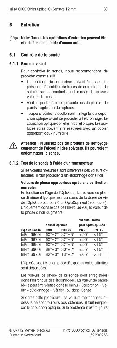
6 Entretien
Note : Toutes les opérations d’entretien peuvent êtreeffectuées sans l’aide d’aucun outil.
6.1 Contrôle de la sonde
6.1.1 Examen visuel
Pour contrôler la sonde, nous recommandons de procéder comme suit :• Les contacts du connecteur doivent être secs. La
présence d’humidité, de traces de corrosion et desaletés sur les contacts peut causer de fausses valeurs de mesure.
• Vérifier que le câble ne présente pas de pliures, depoints fragiles ou de ruptures.
• Toujours vérifier visuellement l’intégrité du capu-chon optique avant de procéder à l’étalonnage. Lecapuchon optique doit être intact et propre. Les sur-faces sales doivent être essuyées avec un papierabsorbant doux humidifié.
Attention ! N’utilisez pas de produits de nettoyagecontenant de l’alcool ni des solvants. Ils pourraientendommager la sonde.
6.1.2 Test de la sonde à l’aide d’un transmetteur
Si les valeurs mesurées sont différentes des valeurs at-tendues, il faut procéder à un étalonnage dans l’air.
Valeurs de phase appropriées aprés une calibrationcorrecte :En fonction de l’âge de l’OptoCap, les valeurs de pha-se diminuent typiquement au cours de la durée de viede l’OptoCap comparé à un OptoCap neuf (voir table).Uniquement dans le cas de l’InPro 6970i, la valeur dela phase à l’air augmente.
Valeurs limites Nouvel OptoCap pour OptoCap usés
Type de Sonde Phi0 Phi100 Phi0 Phi100InPro 6860i 60°±2° 32°±3° <50° <15°InPro 6870i 60°±2° 32°±3° <50° <15°InPro 6880i 60°±2° 32°±3° <50° <15°InPro 6960i 68°±3° 30°±2° <55° <15°InPro 6970i 82°±3° 13°±2° <65° >18°
L’OptoCap doit être remplacé dès que les valeurs limitessont dépassées.
Les valeurs de phase de la sonde sont enregistréesdans l’historique des étalonnages. La valeur de phaseréelle peut être vérifiée dans le menu « Calibration – Ve-rify » (Étalonnage – Vérifier) ou dans iSense.
Si après cette procédure, les valeurs mentionnées ci-dessus ne sont toujours pas obtenues, il faut rempla-cer le capuchon optique. Si le problème n’est toujours
© 07 / 12 Mettler-Toledo AG InPro 6000 optical O2 sensors Printed in Switzerland 52 206 256
InPro 6000 Series Optical O2 Sensors 12 mm 83

pas résolu, envoyer la sonde au représentant local deMETTLER TOLEDO pour examen.La mesure du zéro d’oxygène peut être faite en utili-sant CO2 ou l’azote (N2), dans un échantillon saturé enun de ces gaz.
Après 2 minutes dans un milieu exempt d’oxygène, lasonde doit indiquer moins de 5% de la valeur de mesure dans l’air et, après 10 minutes, moins de 1%de cette valeur.
Si les valeurs indiquées ci-dessus ne sont pas at-teintes, vous devez alors remplacer l’OptoCap. Si cet-te mesure ne corrige toujours pas le resultat, renvoyezla sonde pour inspection à votre agence METTLER TOLEDO.
De nombreux échantillons contiennent des substancesvolatiles qui, même à très faible concentration, ont uneodeur parfaitement perceptible. Tout comme l’oxygène,ces substances peuvent pénétrer dans le capuchon op-tique. En conséquence, elles deviennent perceptibleslorsqu’elles interagissent avec le pigment. Dans la plu-part des cas, de telles substances n’ont aucune influen-ce sur les performances de mesure de la sonde.
6.1.3 ISM
DLI (Dynamic Lifetime Indicator) : Indicateur detemps de vie dynamiqueLe DLI donne des informations concernant la durée de vierestante de l’OptoCap. Tant que le DLI n’est pas arrivé àéchéance, le système fonctionne suivant la précision in-diquée après calibration. Dès que le DLI est à zéro, l’Op-toCap doit être remplacé.
Facteurs qui contribuent à l’usure de l’OptoCap:• Nombre de mesures• Température pendant la mesure• Concentration d’oxygène pendant la mesure• Nombre de cycles NEP• Nombres de cycles SEP• Nombre d’autoclavages
Le DLI est calculé de deux manières différentes.
En mode continu pendant la mesure : sur la base desparamètres cités plus haut, le stress subi par la sondeest estimé. Après chaque mesure, le stress sur la son-de augmente. La somme du stress sur la sonde divisépar la durée de vie écoulée de la sonde sert de basepour le calcul de la durée de vie restante.
Pendant la calibration: les valeurs de phase sont com-parées aux valeurs de calibration précédentes. La du-rée de vie restante de l’OptoCap est calculée ensembleavec le stress total de la sonde, ainsi que la durée devie écoulée. Le calcul après calibration aboutit à unevaleur de DLI qui est plus précise que celle obtenuependant le mode continu. Les valeurs DLI peuvent enconséquence être drastiquement corrigés après unecalibration.
Note : Pour une estimation correcte du DLI, une cali-bration précise est requise.
InPro 6000 optical O2 sensors © 07 / 12 Mettler-Toledo AG52 206 256 Printed in Switzerland
84 InPro 6000 Series Optical O2 Sensors 12 mm

ACT (Adaptive Calibration Timer) : Minuteur d’éta-lonnage adaptatifLe compteur ACT informe quand la sonde devrait êtreà nouveau calibrée pour mesurer avec la précisionspécifiée. Cette information est estimée sur la base dela valeur du DLI. Pour autant que le compteur ACT n’estpas arrivé à zéro, la sonde mesure dans la plage deprécision spécifiée dans la fiche technique.
Historique de calibrationLes données des quatre dernières calibrations et cellesde la calibration d’usine sont enregistrées dans la son-de. Ces données peuvent être lues au moyen du trans-metteur ou du logiciel iSense.
L’historique de calibration fournit des informationsutiles sur la qualité de la calibration et sur l’usure del’OptoCap.
6.2 Remplacement du capuchon optique
Pour remplacer le capuchon optique, il faut au préa-lable dévisser le manchon du capuchon.
Attention ! Quand le manchon du capuchon est enle-vé, faire attention à la partie interne du corps de la son-de. Si les parties internes et les fibres optiques sont en-dommagées ou souillées, cela peut altérer le signal oudétruire la sonde. Les petites souillures peuvent être en-levées avec un chiffon non pelucheux.
Lors du changement de capuchon optique, respecterles instructions suivantes :
Attention ! Assurez-vous que les étapes de travail suivantes sont effectuées dans un environnementpropre.
Attention ! Dans le cas de la sonde InPro 6860i, lemanchon et l’OptoCap forment une pièce unique. Pourremplacer l’OptoCap, il est nécessaire de changer l’uni-té complète.1. Dévisser la gaine de la tige de sonde et la retirer
avec précaution.2. Enlever le capuchon optique.3. Placer le nouveau capuchon optique en haut de la
partie interne du corps de la sonde.4. Faire glisser délicatement le manchon du capuchon
sur le capuchon optique mis en place et visser. Lemanchon du capuchon doit être propre et sec.
5. Après chaque remplacement de l’OptoCap, le té-moin de durée de vie DLI doit être réinitialisé ma-nuellement à l’aide du transmetteur ou du logicieliSense.
6. De même, chaque fois que la membrane est chan-gée, la sonde doit être réétalonnée en deux points.
Attention ! La qualité de cet étalonnage est essentiel-le pour assurer le bon fonctionnement de la sonde etl’exactitude des diagnostics.
© 07 / 12 Mettler-Toledo AG InPro 6000 optical O2 sensors Printed in Switzerland 52 206 256
InPro 6000 Series Optical O2 Sensors 12 mm 85

Remplacer le OptoCap
InPro 6870i/6880i/ InPro 6860i6960i/6970i
5 Pin connector
Sensor head
Threaded sleevePg 13.5
WasherO-Ring
Corps de sonde
[ 12 mm
Corps interne
Joint torique
Cellule optique (OptoCap)Joint toriqueJoint torique
Manchon
a
InPro 6870 iInPro 6960 iInPro 6970 i: The sensor head is not separable from the sensor shaft.
InPro 6880 i
InPro 6860 i
VP connector
Sensor head
Threaded sleevePg 13.5
Washer
O-Ring
Corps de sonde
[ 12 mm
Module optique
Joint torique
Cellule optique
(OptoCap)
InPro 6000 optical O2 sensors © 07 / 12 Mettler-Toledo AG52 206 256 Printed in Switzerland
86 InPro 6000 Series Optical O2 Sensors 12 mm

7 Conservation
La sonde doit être rangée propre et sèche. Les élémentsde protection doivent être placés sur la sonde et sur lesconnecteurs de câble. Si le corps de la sonde est ran-gé sans la tête de la sonde, l’élément de protection doitêtre utilisé pour protéger les fibres optiques.
© 07 / 12 Mettler-Toledo AG InPro 6000 optical O2 sensors Printed in Switzerland 52 206 256
InPro 6000 Series Optical O2 Sensors 12 mm 87
8 Caractéristiques du produit
8.1 Certificats
Chaque sonde est livré avec un jeu de certificats 3.1(en conformité avec la norme EN10204.3/1.B).
Toutes les pièces métalliques en contact avec le milieu(axe de la sonde, gaine et OptoCap) sont identifiées àl’aide d’un symbole correspondant au numéro de coulée. Le symbole gravé sur la sonde correspond aunuméro de coulée qui figure sur le certificat papier délivré avec la sonde.
Chaque pièce métallique en contact avec le milieu(axe de la sonde, gaine et OptoCap) est polie de manière à obtenir une rugosité de surface inférieure à0,4 µm. Cela équivaut à un niveau de rugosité de N5 (selon la norme ISO1320:1992).
InPro 6000 optical O2 sensors © 07 / 12 Mettler-Toledo AG52 206 256 Printed in Switzerland
88 InPro 6000 Series Optical O2 Sensors 12 mm

8.2 Spécifications
InPro 6860i/6880 i / 6870 i /6960i/6970 i
Principe de mesure optiqueConditions d’utilisationDomaine de pression admissible InPro 6860i /6880i /6870i :(mesure) 0,2...6 bar absolu
InPro 6960i :0,2…9 bar absoluInPro 6970i :0,2…12 bar absolu
Domaine de pression InPro 6860i /6880i /6870i :( résistance mécanique) max. 6 bar absolu
InPro 6960i /6970i :12 bar absolu
Domaine de température admissible InPro 6860i /(mesure) InPro 6880i / InPro 6960i /
InPro 6870i : InPro 6970i :0…60°C 0…40°C
Domaine de température max. InPro 6870i /( résistance mécanique) du tige InPro 6860i / InPro 6960i /du capteur InPro 6880i : InPro 6960i :
–20...140°C –20...121°Cstérilisable à stérilisable àla vapeur la vapeurautoclavableInPro 6880i corps seulement
Caractéristique de la sondeDomaine de mesure InPro 6860i/6880i /6870i /6960i:
8 ppb jusqu’à 60% de saturation O2InPro 6970i:2 ppb jusqu’à 2000 ppb
Précision en milieux acqueux InPro 6860i/6880i/6870i /6960i :† ±[1%+8 ppb]InPro 6970i :† ±[2%+2 ppb]
Temps de résponse25 °C (air › N2) t98% < 20 s, < 70 s (InPro 6860i)AvantagesCompensation de la température Automatique avec RTD intégréConnexion du câble (digital ) Câble de données à 5 broches,
VP8 (InPro 6860i)Matériaux des joints toriques EPDM FDA approuvé en contact produit (autres matériaux sur demande)Matériaux de la membrane Silicone, PTFE (InPro 6860i) Matériaux (corps de sonde) en Acier 1.4404, [AISI 316L] PPS contact produit avec certificat 3.1 (autres matériaux
sur demande)Rugosité des pièces en acieren contact produit(EN1320: 1996) Ra <0,4µmCertificats (MaxCert™)Contrôle qualité ouiFDA/USP VI ouiCertificat matériau 3.1 ouiCertificat état de surface 2.1 oui
© 07 / 12 Mettler-Toledo AG InPro 6000 optical O2 sensors Printed in Switzerland 52 206 256
InPro 6000 Series Optical O2 Sensors 12 mm 89

9 Informations pour la commande
Pour de plus amples informations consultez la fichetechnique. Veuillez la demander à votre fournisseur.
9.1 Sondes
Désignation du produit
9.2 Accessoires
Accessoires Node comm.iSense Asset Suite 52 900 336CalBox 52 300 400iLink RS485 52 300 399iLink RS485-VP (InPro 6860i) 30 014 134
Câble de données (5 broches) pourInPro 6870i /6880i /6960i /6970iPlage de temperature –30…80°C2 m 52 300 3795 m 52 300 38010 m 52 300 38115 m 52 206 42225 m 52 206 52950 m 52 206 530
Sondes Node comm.InPro 6860i /12/120 mm 30 014 100InPro 6860i /12/220 mm 30 014 101InPro 6860i /12/320 mm 30 014 102InPro 6860i /12/420 mm 30 014 103
InPro 6880i /12/120 mm 52 206 242InPro 6880i /12/220 mm 52 206 243InPro 6880i /12/320 mm 52 206 244InPro 6880i /12/420 mm 52 206 245
InPro 6870i /12/120 mm 52 206 380InPro 6870i /12/220 mm 52 206 381InPro 6870i /12/320 mm 52 206 382InPro 6870i /12/420 mm 52 206 383
InPro 6960i /12/120 mm 52 206 500InPro 6960i /12/220 mm 52 206 501InPro 6960i /12/320 mm 52 206 502
InPro 6970i /12/120 mm 52 206 393InPro 6970i /12/220 mm 52 206 394InPro 6970i /12/320 mm 52 206 395
InPro 6880 i/ 12/_ _ _
Longueur d’immersion (a) en mm
Diamètre de la sonde:12 = 12 mm
InPro 6000 optical O2 sensors © 07 / 12 Mettler-Toledo AG52 206 256 Printed in Switzerland
90 InPro 6000 Series Optical O2 Sensors 12 mm

9.3 Pièces détachées
9.4 Transmetteurs recommandés
Transmitter Node comm.M400, Type 2 52 121 349M400, Type 3 (InPro 6960i / InPro 6970i) 52 121 350M800 2-channel 52 121 813M800 4-channel 52 121 853
Accessoires Node comm.Alimentation électrique 300 14 119
Câble de données pour InPro 6860iPlage de temperature –30…80°C ( –22…176°F)
VP8 -ST (connexion numérique et analogique)1 m 52 300 3533 m 52 300 3545 m 52 300 35510 m 52 300 35615 m 52 206 45720 m 52 206 55835 m 52 206 559
VP6-ST (connexion anlogique seulement)1 m 52 300 1073 m 52 300 1085 m 52 300 10910 m 52 300 11015 m 52 300 14120 m 52 300 14435 m 52 300 184
VP6 pour l’InPro 6860i preconfiguré avec connecteurCâble avec connecteur BNC, 1 m 30 032 730Câble avec connecteur BNC, 3 m 30 032 731Câble avec connecteur LEMO, 1 m 30 032 732Câble avec connecteur LEMO, 3 m 30 032 733Câble avec connecteur Lumberg, 1 m 30 032 734Câble avec connecteur Lumberg, 3 m 30 032 735
Pièces détachées Node comm.OptoCap BT 01 (InPro 6880i /6870i) 52 206 225OptoCap BT 02 T (InPro 6860i), 30 018 857joint torique incluOptoCap BR 01 (InPro 6970i) 52 206 403OptoCap BW01 (InPro 6960i) 52 206 509Kit de joint silicone 52 206 252Manchon 52 206 232Elément de protection 52 206 251
© 07 / 12 Mettler-Toledo AG InPro 6000 optical O2 sensors Printed in Switzerland 52 206 256
InPro 6000 Series Optical O2 Sensors 12 mm 91

92 InPro 6000 Series Optical O2 Sensors 12 mm
InPro 6000 optical O2 sensors © 07 / 12 Mettler-Toledo AG52 206 256 Printed in Switzerland
9.5 Supports recommandés
Note : Les supports étant disponible dans différentes finitions, veuillez prendre contact avec votre revendeurpour vous assurez que les numéros de commandecorrespondent bien avec la finition désirée.
Support fixe Node comm.InFit 761 –Support rétractableInTrac 777 e –InTrac 797 e –
Kit de rétromontage, optique 52 403 811

InPro 6000 Series Optical O2 Sensors 12 mm 93
© 07 / 12 Mettler-Toledo AG InPro 6000 optical O2 sensors Printed in Switzerland 52 206 256
10 Théorie de l’oxymétrie optique
10.1 Introduction
L’oxymétrie optique est une méthode non invasive. Au-cune réaction électrochimique n’a lieu pendant la me-sure.
10.2 Principe
Contrairement aux méthodes ampérométriques et po-tentiométriques, la méthode de mesure optique n’estpas fondée sur une réaction électrochimique ou unemesure de courant.Un chromophore situé dans la sonde est éclairé par dela lumière bleue. Le chromophore absorbe cette éner-gie et passe à un niveau d’énergie supérieur (état ex-cité). Une partie de l’énergie est dissipée sous formede chaleur. Après un court délai, le chromophore émetune fluorescence rouge et revient à son état initial.Si une molécule d’oxygène entre en collision avec lechromophore à l’état excité, l’énergie peut être transfé-rée à l’oxygène (extinction dynamique). Dans ce cas,il n’y a pas d’émission de fluorescence. L’oxygène lui-même peut dissiper cette énergie sous forme de cha-leur, sans émission de lumière.L’émission de fluorescence dépend donc de la pres-sion partielle d’oxygène au niveau de la couche dechromophore.L’émission de fluorescence a lieu avec un léger déca-lage de temps par rapport à l’excitation. Ce temps deréponse peut être mesuré en fonction des modulationsde la lumière excitatrice. Dans ce cas, on observe unemodulation identique de la fluorescence.Le décalage de phase entre l’excitation et l’émission defluorescence diminue lorsque la concentration en oxy-gène augmente.La concentration en oxygène est calculée et transféréenumériquement au transmetteur.
10.3 Principe de conception de la sonde à oxygèneoptique
Filtre optiqueRéférence
LEDDétec-teur
Excitation Diode
électrolumi-nescente
(LED)
Fibre optique
Sonde de température
Manchon ducapuchon
Joint torique
Couche optique avecchromophore
Corps métallique
Verre
Isolation optique (silicone noir)
Tête dela sonde
Corps dela sonde
OptoCap

94 InPro 6000 Series Optical O2 Sensors 12 mm
InPro 6000 optical O2 sensors © 07 / 12 Mettler-Toledo AG52 206 256 Printed in Switzerland
10.4 Température
Les sondes à oxygène optiques contiennent un capteurde température à résistance (RTD) et la températureest compensée automatiquement.
10.5 Dépendance du flux
Par rapport aux capteurs ampérométriques, les sondesà oxygène optiques possèdent une sensibilité au fluxnettement plus faible.
Cela s’explique par le fait que la sonde ne réduit pasl’oxygène. Il n’y a pas de variation de la concentrationen oxygène au niveau de la sonde.
10.6 Pression partielle d’oxygène – concentration en oxygène
Le signal de la sonde dépend de la pression partielled’oxygène et la perméabilité à l’oxygène de la membrane et non de la solubilité O2 dans les solutions.La concentration en oxygène en mg O2/ L (CL) ne peutdès lors pas être déterminée directement au moyend’une électrode.Selon la loi d’Henry, la concentration en oxygène estproportionnelle à sa pression partielle (PO2).
CL = pO2 • aa = facteur de solubilité
Si «a» est une constante et connue, la concentrationen oxygène peut être déterminée au moyen d’une élec-trode. Ce principe s’applique à une températureconstante et dans le cas de solutions aqueuses diluéestelles que l’eau potable.Le facteur de solubilité est fortement influencé par latempérature mais également par la composition de lasolution :
Bien que leurs solubilités soient totalement différentes,la sonde à oxygène donne le même résultat dans les3 solutions.Ainsi donc, la détermination de la concentration enoxygène n’est possible qu’avec des facteurs de solu-bilité «a» connus et constants.La solubilité peut être déterminée par un titrage Winklerou suivant la méthode décrite par Käppeli et Fiechter.
Références– W.M. Krebs, I.A. Haddad Develp. Ind. Microbio.,
13, 113 (1972)– H. Bühler, W. Ingold GIT 20, 977 (1976)– W.M. Krebs, MBAA Techn. Quart. 16, 176 (1975)– D.P. Lucero, Ana. Chem. 40, 707 (1968)
Milieu, sat. avec air Solubilité à 20°C et 1013 mbar (760 mm Hg)
Eau 9,2 mg O2/L4 mol /L KCI 2 mg O2/L50% Méthanol-eau 21,9 mg O2/L

InPro 6000 Series Optical O2 Sensors 12 mm 95
© 07 / 12 Mettler-Toledo AG InPro 6000 optical O2 sensors Printed in Switzerland 52 206 256
Note :

BR Mettler-Toledo Ind. e Com. Ltda., Alameda Araguaia, 451 - Alphaville, BR -06455-000 Barueri / SP, BrazilPhone +55 11 4166 7444, Fax +55 11 4166 7401
CH Mettler-Toledo (Schweiz) GmbH, Im Langacher, CH-8606 Greifensee, SwitzerlandPhone +41 44 944 45 45, Fax +41 44 944 45 10
D Mettler-Toledo GmbH, Prozeßanalytik, Ockerweg 3, D-35396 Gießen, GermanyPhone +49 641 507-333, Fax +49 641 507-397
F Mettler-Toledo Analyse Industrielle S.A.S., 30, Bld. de Douaumont, F -75017 Paris, FrancePhone +33 1 47 37 06 00, Fax +33 1 47 37 46 26
USA Mettler-Toledo Ingold, Inc., 36 Middlesex Turnpike, Bedford, MA 01730 USAPhone +1 800 352 8763, Fax +1 781 271 0681
Mettler-Toledo AG, Process Analytics, Im Hackacker 15, CH-8902 Urdorf, SwitzerlandPhone +41 44 729 62 11, Fax +41 44 729 66 36, Internet: www.mt.com/proSubject to technical changes. 07 / 12 © Mettler-Toledo AG. Printed in Switzerland. 52 206 256
96 InPro 6000 Series Optical O2 Sensors 12 mm