‘Inorganic Gel Casting’ and Sinter-Crystallization
12
Materials 2018, 11, 349; doi: 10.3390/ma11030349 www.mdpi.com/journal/materials Article Bioactive Glass-Ceramic Foam Scaffolds from ‘Inorganic Gel Casting’ and Sinter-Crystallization Hamada Elsayed 1,2 , Acacio Rincón Romero 1 , Giulia Molino 3 , Chiara Vitale Brovarone 3 and Enrico Bernardo 1, * 1 Department of Industrial Engineering, University of Padova, Via Marzolo 9, 35131 Padova, Italy; [email protected] (H.E.); [email protected] (A.R.R.) 2 Ceramics Department, National Research Centre, El-Bohous Street, Cairo 12622, Egypt 3 Dipartimento Scienza Applicata e Tecnologia, Politecnico di Torino, 10129 Torino, Italy; [email protected] (G.M.); [email protected] (C.V.B.) * Correspondence: [email protected] Tel.: +39-049-827-5510; Fax: +39-049-827-5505 Received: 11 January 2018; Accepted: 24 February 2018; Published: 27 February 2018 Abstract: Highly porous bioactive glass-ceramic scaffolds were effectively fabricated by an inorganic gel casting technique, based on alkali activation and gelification, followed by viscous flow sintering. Glass powders, already known to yield a bioactive sintered glass-ceramic (CEL2) were dispersed in an alkaline solution, with partial dissolution of glass powders. The obtained glass suspensions underwent progressive hardening, by curing at low temperature (40 °C), owing to the formation of a C–S–H (calcium silicate hydrate) gel. As successful direct foaming was achieved by vigorous mechanical stirring of gelified suspensions, comprising also a surfactant. The developed cellular structures were later heat-treated at 900–1000 °C, to form CEL2 glass-ceramic foams, featuring an abundant total porosity (from 60% to 80%) and well-interconnected macro- and micro- sized cells. The developed foams possessed a compressive strength from 2.5 to 5 MPa, which is in the range of human trabecular bone strength. Therefore, CEL2 glass-ceramics can be proposed for bone substitutions. Keywords: CEL2 glass; glass-ceramics; alkali activation; gel casting 1. Introduction Owing to the worldwide increase of population and raise of life expectancy, there is an increasing demand for bone grafts or synthetic materials that can potentially replace, repair or regenerate bone defects [1]. Tissue engineering (TE) is one of the fundamental solutions, implemented to challenge this problem [2]. Natural and synthetic materials, which are used to supply, replenish or enhance the living tissue functionality, are regarded as ‘biomaterials’ [3]. Within them, ‘bioceramics’, to be used for repairing and reconstructing of diseased or damaged parts of the musculo-skeletal system, - also known as ‘bioceramics’, are classified as bioinert (alumina, zirconia), bioresorbable (tricalcium phosphate) or even bioactive (hydroxyapatite, bioactive glasses, and glass- ceramics) [4]. A highly porous structure is often appreciated, e.g., for tissue ingrowth [5]. The bioactivity attributed to some glasses is due to the formation of a hydroxyl carbonated apatite layer (HCA) on their surface similar to bone mineral [5]. This HCA layer forms as a result of a rapid sequence of chemical reactions on the surface of the implant when in contact with body fluids. A well-recognized method to estimate the bone-bonding potential ability of a material, according to Kokubo et al. [6], involves its immersion into simulated body fluid (SBF), followed by the evaluation of bone-like apatite formation on the surface. In other words, the behavior in vivo may be predicted by using the SBF method in vitro, and observing the occurrence of several reactions, including the rapid release of soluble ionic species and the formation of a high surface area layer, consisting of
Transcript of ‘Inorganic Gel Casting’ and Sinter-Crystallization

Materials 2018, 11, 349; doi: 10.3390/ma11030349 www.mdpi.com/journal/materials
Article
Bioactive Glass-Ceramic Foam Scaffolds from
‘Inorganic Gel Casting’ and Sinter-Crystallization
Hamada Elsayed 1,2, Acacio Rincón Romero 1, Giulia Molino 3, Chiara Vitale Brovarone 3 and
Enrico Bernardo 1,*
1 Department of Industrial Engineering, University of Padova, Via Marzolo 9, 35131 Padova, Italy;
[email protected] (H.E.); [email protected] (A.R.R.) 2 Ceramics Department, National Research Centre, El-Bohous Street, Cairo 12622, Egypt 3 Dipartimento Scienza Applicata e Tecnologia, Politecnico di Torino, 10129 Torino, Italy;
[email protected] (G.M.); [email protected] (C.V.B.)
* Correspondence: [email protected] Tel.: +39-049-827-5510; Fax: +39-049-827-5505
Received: 11 January 2018; Accepted: 24 February 2018; Published: 27 February 2018
Abstract: Highly porous bioactive glass-ceramic scaffolds were effectively fabricated by an
inorganic gel casting technique, based on alkali activation and gelification, followed by viscous flow
sintering. Glass powders, already known to yield a bioactive sintered glass-ceramic (CEL2) were
dispersed in an alkaline solution, with partial dissolution of glass powders. The obtained glass
suspensions underwent progressive hardening, by curing at low temperature (40 °C), owing to the
formation of a C–S–H (calcium silicate hydrate) gel. As successful direct foaming was achieved by
vigorous mechanical stirring of gelified suspensions, comprising also a surfactant. The developed
cellular structures were later heat-treated at 900–1000 °C, to form CEL2 glass-ceramic foams,
featuring an abundant total porosity (from 60% to 80%) and well-interconnected macro- and micro-
sized cells. The developed foams possessed a compressive strength from 2.5 to 5 MPa, which is in
the range of human trabecular bone strength. Therefore, CEL2 glass-ceramics can be proposed for
bone substitutions.
Keywords: CEL2 glass; glass-ceramics; alkali activation; gel casting
1. Introduction
Owing to the worldwide increase of population and raise of life expectancy, there is an
increasing demand for bone grafts or synthetic materials that can potentially replace, repair or
regenerate bone defects [1]. Tissue engineering (TE) is one of the fundamental solutions,
implemented to challenge this problem [2]. Natural and synthetic materials, which are used to
supply, replenish or enhance the living tissue functionality, are regarded as ‘biomaterials’ [3]. Within
them, ‘bioceramics’, to be used for repairing and reconstructing of diseased or damaged parts of the
musculo-skeletal system, - also known as ‘bioceramics’, are classified as bioinert (alumina, zirconia),
bioresorbable (tricalcium phosphate) or even bioactive (hydroxyapatite, bioactive glasses, and glass-
ceramics) [4]. A highly porous structure is often appreciated, e.g., for tissue ingrowth [5].
The bioactivity attributed to some glasses is due to the formation of a hydroxyl carbonated
apatite layer (HCA) on their surface similar to bone mineral [5]. This HCA layer forms as a result of
a rapid sequence of chemical reactions on the surface of the implant when in contact with body fluids.
A well-recognized method to estimate the bone-bonding potential ability of a material, according to
Kokubo et al. [6], involves its immersion into simulated body fluid (SBF), followed by the evaluation
of bone-like apatite formation on the surface. In other words, the behavior in vivo may be predicted
by using the SBF method in vitro, and observing the occurrence of several reactions, including the
rapid release of soluble ionic species and the formation of a high surface area layer, consisting of

Materials 2018, 11, 349 2 of 12
hydrated silica and polycrystalline carbonated hydroxyapatite (HCA) [7,8], under rather strict
conditions of pH. In fact, it is known that osteoblasts prefer a slightly alkaline medium
(pH = 7.8) [9]; severe changes in pH, as a result of ion release, can inhibit osteoblast activity and can
cause cell necrosis or apoptosis [10,11].
CEL2 bioactive glass, belonging to the SiO2–P2O5–CaO–MgO–K2O–Na2O system, was
specifically tailored to control pH variations, due to ion leaching phenomena, when in contact with
physiological fluids. Therefore, CEL2 glass features a lower overall alkali content (less than 20 mol
%) and a slightly higher P2O5 content (3 mol %) compared to commercial bioactive glasses. CEL2
glass-ceramic was effectively found to be highly biocompatible and bioactive; in addition, unlike in
many bioactive glasses, the positive effect on the mechanical properties imparted by the partial
crystallization is not negatively counterbalanced by any decrease of its bioactivity [12,13].
As mentioned above, many bioceramics are in form of highly porous, open-celled bodies, also
known as ‘scaffolds’. Glass and glass-ceramic scaffolds can be prepared by using different methods,
such as free form fabrication techniques [14], sponge replication [15,16], starch consolidation [17] and
burn-out of sacrificial polymeric particles [18]. Concerning CEL2 glass-ceramic, macroporous
scaffolds for possible use as bone substitutes were prepared both by sponge replication [13] and burn-
out method [19]. Both methods imply the quite delicate removal, by thermal degradation, of an
organic phase, acting as a template for the cellular structure (e.g., operating with polyurethane
sponge) or for the pores (e.g., operating with fugitive pore formers), followed by viscous flow
sintering of glass powders, in turn accompanied by a partial crystallization. Especially in the case of
sponge replication, the obtainment of high quality components relies on a careful selection of all
processing conditions. Before thermal processing, the impregnation of the starting sponge, with an
aqueous slurry of glass powders added with a binder (polyvinyl alcohol, PVA), must be absolutely
uniform. Upon firing, the viscous flow of the glass should be enough to fill the cavities left by the
burn-out of former polymeric struts otherwise low mechanical strength can be expected [20].
The present paper illustrates the extension to CEL2 glass-ceramics of a gel casting process,
recently established [21,22]. The method implies the obtainment of cellular structures by direct
foaming of engineered glass slurries, followed by sintering. More precisely, CEL2 glass powders were
exposed to an alkaline solution, with partial dissolution. The gelation of partially dissolved products
(‘inorganic gel casting’) caused a marked hardening of glass suspensions, so that they could be
significantly foamed by air incorporation, under intensive mechanical stirring, with the help of a
surfactant. Highly porous cellular structures could be tuned simply by adjusting the formulation of
slurries; the crystallization of CEL2, upon firing, was significant in ‘freezing’ the microstructure,
impeding any viscous collapse.
2. Experimental Procedure
2.1. Starting Glass
The chosen bioactive glass used as a reference material for the present investigation consisted of
a glass belonging to the SiO2–P2O5–CaO–MgO–Na2O–K2O system. This reference glass, named CEL2,
had the following molar composition: 45% SiO2, 3% P2O5, 26% CaO, 7% MgO, 15% Na2O, 4% K2O.
The glass was prepared by melting reagent-grade reactants in a platinum crucible at 1400 °C for 1 h.
The molten glass was poured into water to obtain a frit that was subsequently ball-milled to obtain
powders, which were later manually sieved. CEL2 glass powder was analyzed through differential
thermal analysis (DTA, Netzsch STA 429, Selb, Germany), with heating rate of 10 °C/min up to
1000 °C in air, to evaluate its characteristic temperatures. For foaming experiments, only powders
with a diameter below 75 µm were considered.
2.2. Preparation and Microstructural Characterization of Foams
To fabricate CEL2 glass-ceramic scaffolds for bone substitutions, fine CEL2 glass powders were
mixed with an aqueous solution containing 1 M NaOH (reagent grade, Sigma-Aldrich, Gillingham,
UK), for a solid loading of 58 and 60 wt %. The glass slurries were kept under low speed mechanical

Materials 2018, 11, 349 3 of 12
stirring (500 rpm) for 3h, for alkaline activation and partial gelation, and then cast in several
polystyrene cylindrical moulds (60 mm diameter). After the addition of 4 wt % Triton X-100
(polyoxyethylene octyl phenyl ether—C14H22O(C2H4O)n, n = 9–10, Sigma-Aldrich, Gillingham, UK),
consisting of a non-ionic surfactant that does not interfere with ceramic dispersions [23], the slurries
were foamed by vigorous mechanical mixing (2000 rpm), for 5 min.
The foamed slurries were later left at 40 °C for 24 h, in order to complete the gelation, before
demolding. The obtained ‘green’ foams could be easily handled and placed in a muffle furnace, for
the final sintering treatments, at 900–1000 °C for 1 h, followed by natural cooling. The thermal
treatment comprised an intermediate step at 300 °C for 2 h to remove any absorbed water and organic
residues, after a slow heating phase (2 °C/min); the subsequent heating up to the selected firing
temperature was performed at 5 °C/min. Figure.1 describes the process used for manufacturing CEL2
glass-ceramic foams.
Figure 1. Processing scheme for the obtainment of CEL2 glass-ceramic foams by combination of alkali
activation, gel casting and sintering.
2.3. Characterization and Microstructural Investigation of CEL2 Foams
For understanding the thermal behavior, CEL2 glass powders and foamed gels were subjected
to thermogravimetric analysis (TGA, STA409, Netzsch Gerätebau GmbH, Selb, Germany).
Fourier transform IR spectroscopy (FTIR, FTIR model 2000, Perkin Elmer Waltham, MA, USA)
measurements were made for the dry CEL2 glass powder and for CEL2 glass foams, with a solid load
of 60 wt %, in form of green foams and after heat treatment at 900 °C. FTIR analysis were conducted
on solid discs (with 13 mm diameter), prepared by mixing powdered samples with KBr powder (2
mg dispersed in 200 mg of KBr). The FTIR spectra were collected in the 4000–400 cm−1 range.
The phase assemblages were performed by means of X-ray diffraction on powdered samples
(XRD; Bruker D8 Advance, Bruker AXS GmbH, Karlsruhe, Germany), supported by data from PDF-
2 database (ICDD-International Centre for Diffraction Data, Newtown Square, PA, USA) and Match!
program package (Crystal Impact GbR, Bonn, Germany). X-ray diffraction analysis were performed
using a scanning range 2θ from 10° to 70° with a scanning rate of 0.05°/step, and an analysis time of
2 s/step.
Nano-CT (SkyScan 1272, Bruker microCT, Kontich, Belgium) experiments were performed on
CEL2 glass-ceramic foams with different solid loads, using a X-ray beam generated by a tungsten
filament charged by a voltage of 70 kV and a current of 142 µA. Samples were analyzed over a
rotation range of 180°, with a step of 0.02°, an exposure time of 3250 ms per projection and a pixel
size of 5.37 µm. The so-collected shadow images have been first reconstructed using a filtered back-
projection algorithm (NRecon, Bruker, Bruker microCT, Kontich, Belgium), then sample 3-D
structures was obtained from the reconstructed images by means of a specific software (Bruker
CTvox software, Mannheim, Germany). A volume of interest (VOI) was selected for each sample in
order to analyze its structural parameters (Bruker CTan Software, Mannheim, Germany), after image
binarization. In particular, for the analysis of pore interconnectivity the “shrink wrap” function has
been applied in the 3D VOI. This function allows shrinking the outside boundary of the VOI through

Materials 2018, 11, 349 4 of 12
any openings whose connection size is larger than a threshold value (set in this work from 0 µm to
170 µm), identifying consequently the inaccessible regions of the scaffold comprised in the VOI. For
each threshold value, the % interconnectivity has been calculated applying the following equation:
% 𝐼𝑛𝑡𝑒𝑟𝑐𝑜𝑛𝑛𝑒𝑐𝑡𝑖𝑣𝑖𝑡𝑦 =(𝑉 − 𝑉𝑠ℎ𝑟𝑖𝑛𝑘−𝑤𝑟𝑎𝑝)
(𝑉 − 𝑉𝑚)× 100 (1)
where V is the total VOI volume, Vshrink-wrap is the total volume after the application of the shrink-wrap
function and Vm is the scaffold volume comprised in the VOI.
Microstructural characterizations were performed by optical stereomicroscopy (AxioCam ERc
5 s Microscope Camera, Carl Zeiss Microscopy, Thornwood, NY, USA) and scanning electron
microscopy (SEM, FEI Quanta 200 ESEM, FEI Company, Eindhoven, The Netherlands) equipped
with energy dispersive spectroscopy (EDS).
The geometrical density (ρgeom) of CEL2 glass foams was evaluated by considering the mass to
volume ratio. The apparent (ρapp) and the true (ρtrue) density values were measured by using a helium
pycnometer (AccuPyc 1330, Micromeritics, Norcross, GA, USA), operating on bulk or on finely
crushed samples, respectively. The three density values were used to compute the amounts of total
and open porosity.
The compressive strength (c) of CEL2 glass-ceramic foams was measured at room temperature,
by means of an Instron 1121 UTM (Instron, Danvers, MA, USA) operating with a cross-head speed
of 1 mm/min. Each data point represents the average value of 5 to 10 individual tests.
3. Results and discussion
Figure 2a clearly illustrates the great potential of the approach, despite its simplicity.
Homogeneous and highly porous open-celled structures were achieved already in the ‘green’ state.
As previously observed [21], the partial gelation of glass slurries, upon alkaline activation, leads to a
marked pseudoplastic behavior, in analogy with what happens with more common ‘inorganic
polymers’ (including geopolymers). Air bubbles, incorporated by intensive mechanical stirring
(aided by the surfactant), at high shear rates and low viscosity, remain trapped when stirring stops,
at low shear rate and high viscosity [24]. In the present investigation, there was an increase of
100–150% in the volume of slurries, passing from the alkali activation step to the hardened state.
Figure 2. Microstructural and morphology details of CEL2 glass-ceramic foams, with 60 wt %, as solid
load; (a) cured CEL2 green foam; (b) after firing at 900 °C.
The gelation of CEL2 glass was determined by the same compounds previously found after
alkali activation of other CaO-rich glasses [21,22]. More precisely, CaO-rich glasses, upon alkali
activation, are known to yield a ‘zeolite-like’ gel (like that formed in geopolymeric systems, based on
the condensation of alumino-silicate hydrated oligomers, made available by complete alkali
dissolution of alumino-silicate materials), but provide a condensation product that could be termed
‘tobermorite-like’ gel (calcium silicate hydrate, or C–S–H), given the analogy with the products of
cement hydration [25].
Materials 2018, 11, 349 5 of 12
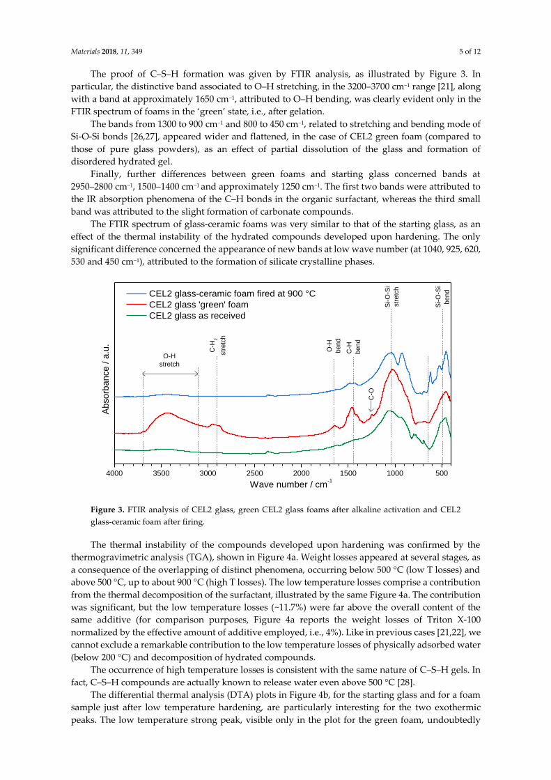
The proof of C–S–H formation was given by FTIR analysis, as illustrated by Figure 3. In
particular, the distinctive band associated to O–H stretching, in the 3200–3700 cm−1 range [21], along
with a band at approximately 1650 cm−1, attributed to O–H bending, was clearly evident only in the
FTIR spectrum of foams in the ‘green’ state, i.e., after gelation.
The bands from 1300 to 900 cm−1 and 800 to 450 cm−1, related to stretching and bending mode of
Si-O-Si bonds [26,27], appeared wider and flattened, in the case of CEL2 green foam (compared to
those of pure glass powders), as an effect of partial dissolution of the glass and formation of
disordered hydrated gel.
Finally, further differences between green foams and starting glass concerned bands at
2950–2800 cm−1, 1500–1400 cm−1 and approximately 1250 cm−1. The first two bands were attributed to
the IR absorption phenomena of the C–H bonds in the organic surfactant, whereas the third small
band was attributed to the slight formation of carbonate compounds.
The FTIR spectrum of glass-ceramic foams was very similar to that of the starting glass, as an
effect of the thermal instability of the hydrated compounds developed upon hardening. The only
significant difference concerned the appearance of new bands at low wave number (at 1040, 925, 620,
530 and 450 cm−1), attributed to the formation of silicate crystalline phases.
Figure 3. FTIR analysis of CEL2 glass, green CEL2 glass foams after alkaline activation and CEL2
glass-ceramic foam after firing.
The thermal instability of the compounds developed upon hardening was confirmed by the
thermogravimetric analysis (TGA), shown in Figure 4a. Weight losses appeared at several stages, as
a consequence of the overlapping of distinct phenomena, occurring below 500 °C (low T losses) and
above 500 °C, up to about 900 °C (high T losses). The low temperature losses comprise a contribution
from the thermal decomposition of the surfactant, illustrated by the same Figure 4a. The contribution
was significant, but the low temperature losses (~11.7%) were far above the overall content of the
same additive (for comparison purposes, Figure 4a reports the weight losses of Triton X-100
normalized by the effective amount of additive employed, i.e., 4%). Like in previous cases [21,22], we
cannot exclude a remarkable contribution to the low temperature losses of physically adsorbed water
(below 200 °C) and decomposition of hydrated compounds.
The occurrence of high temperature losses is consistent with the same nature of C–S–H gels. In
fact, C–S–H compounds are actually known to release water even above 500 °C [28].
The differential thermal analysis (DTA) plots in Figure 4b, for the starting glass and for a foam
sample just after low temperature hardening, are particularly interesting for the two exothermic
peaks. The low temperature strong peak, visible only in the plot for the green foam, undoubtedly
4000 3500 3000 2500 2000 1500 1000 500
CEL2 glass-ceramic foam fired at 900 °C
CEL2 glass 'green' foam
CEL2 glass as received
Ab
so
rba
nce
/ a
.u.
Wave number / cm-1
Si-
O-S
i
str
etc
h
Si-
O-S
i
bend
C-H
bend
C-H
2
str
etc
h
C-O
O-H
bend
O-H
stretch

Materials 2018, 11, 349 6 of 12
corresponds to the burn-out of the surfactant, considering the exact match (at 300 °C) with the onset
of the relative thermal loss (see upper plot in Figure 4a). The broader exothermic peaks at higher
temperatures are significant for the differences between starting glass and green foam: in the as-
received condition, CEL2 glass presented a broad ‘exothermic band’ that could be attributed to the
overlapping of at least two crystallization peaks, at 700 and 750 °C; in the activated condition, the
band became even wider and positioned at lower temperatures. This effect had not been detected
with the alkali activation of previously investigated CaO–MgO–SiO2 glass [22]. In our opinion this
could be justified on the basis of the mixing of two distinct glass phases, consisting of material from
the decomposition of the surface gels and undissolved glass. In particular, the alkali enrichment of
surface gels surrounding glass powders likely lowered the glass transition temperature (Tg),
promoting the ionic inter-diffusion and the crystallization of CEL2 glass (e.g., by reducing the
activation energy for crystal growth [29]). The endothermic effect centered at about 500 °C was
attributed to dehydration of the green foam.
Figure 4. Thermal analysis of CEL2 glass before and after gel-casting; (a) Thermo-gravimetric plot of
alkali-activated CEL2 glass and surfactant “Triton X-100”; (b) Differential thermal analysis of CEL2
glass powder and ‘green’ glass foam from alkali activation and direct foaming.
The promotion of the crystallization had a remarkable impact on the microstructure after firing.
As shown by Figure 2b the open-celled structure was confirmed after firing at 900 °C: the increase of
apparent viscosity, operated by rigid crystal inclusion, evidently prevented any viscous collapse.
The X-ray diffraction patterns reported in Figure 5 provide an overview of the evolution of
crystalline phases in the processing of CEL2 glass-ceramic foams. The XRD pattern of the alkaline-
activated material provided further evidence of gel formation, after foaming and drying of the glass,
due to the slight 2θ displacement the amorphous halo (Figure 5a). The 2θ shift for the green glass
foams, in fact, is consistent with the incorporation of network modifiers [30]. After firing at 900 °C,
the typical crystalline phases of bioactive CEL2 glass-ceramic, such as combeite (Na₄Ca₄Si₆O₁₈,
PDF#79-1089) and akermanite (Ca₂MgSi₂O₇, PDF#83-1815) [13], appeared. Interestingly, another Ca-
Mg silicate (diopside, CaMgSi₂O₆, PDF#75-1092) formed as additional phase; to our opinion, this
could be due the decomposition of the hydrated silicate gels formed upon activation. The
crystallization degree (inferable from the intensity of diffraction lines) increased passing from 900 to
1000 °C (see Figure 5b); in addition, there was a reduction of diopside, with increase of akermanite.
In other words, the firing at 1000 °C made the phase assemblage of the present foams more similar to
that previously reported [13]. The formation of Ca–Mg silicate crystal phases (akermanite or
diopside) is very promising, due to the distinctive combination of remarkable mechanical strength
with excellent bioactivity as well as controlled dissolution rate [31,32].

Materials 2018, 11, 349 7 of 12
Figure 5. X-ray diffraction analysis of CEL2 glass-based materials: (a) evolution from as received state
to alkali-activated and sinter-crystallized state; (b) comparison between firing at 900 and 1000 °C
(foamed samples, from 60 % CEL2 solid loading).
Table 1 reports the physical and mechanical properties of CEL2 glass-ceramic foams after firing.
It can be noticed that samples were produced according to several processing variants, aimed at
exploring different viscosity conditions before firing and during firing. In fact, both steps could be
interpreted according to the mechanics of suspensions, in which the apparent viscosity depends on
the combination of the viscosity of the medium and the amount of suspended, rigid inclusions. An
increase of the solid loading, from 58 to 60 wt %, was expected to cause an increase of the viscosity
of slurries simply on the basis of the amount of inclusions, reducing the expansion upon intensive
mechanical stirring. An increase of the firing temperature, from 900 to 1000 °C, on one hand, was
expected to reduce the viscosity of the residual glass phase, i.e., of the medium in which crystal
inclusions were suspended, enhancing the densification by removal of smaller pores; on the other
hand, the increased crystallization degree (Figure 5b) could determine a substantial reinforcement of
the solid phase. The data reported in Table 1 confirm the expected ‘tuning’ of porosity operating on
solid loading and/or on firing temperature. With a compressive strength ranging from 2.5 ± 0.4 to
15.5 ± 1.7 MPa, the developed foams compare well with the values for cancellous bone (2–12 MPa)
[33,34].
Table 1. Physico-mechanical properties of CEL2 glass-ceramic foams produced by different solid
contents (TP = total porosity, OP = open porosity)
Solid Load
(wt. %)
T
(°C)
ρgeom
(g/cm3)
ρapp
(g/cm3)
ρtrue
(g/cm3)
Relative
Density, ρrel TP (vol %)
OP
(vol %)
c
(MPa)
58 900 0.58 ± 0.03 2.38 ± 0.01 3.06 ± 0.01 0.19 81 ± 5 75 ± 5 2.5 ± 0.4
1000 0.92 ± 0.07 2.05 ± 0.09 3.13 ± 0.02 0.30 70 ± 8 55 ± 1 3.9 ± 0.5
60 900 1.12 ± 0.02 2.49 ± 0.09 3.05 ± 0.01 0.37 63 ± 2 55 ± 5 5.5 ± 0.2
1000 1.16 ± 0.08 2.52 ± 0.04 3.16 ± 0.01 0.37 63 ± 7 52 ± 8 15.5 ± 1.7
It should be noted that the lightest foam, processed at low solid loading and low firing
temperature and exhibiting the lowest strength, could not be considered as ‘weak’. The crushing
strength of cellular solid, σc, according to the well-recognized Gibson-Ashby (GA) model [35],
actually depends on the relative density (ratio between bulk and true densities, ρrel), as follows:
σc ≈ σbend × f(Φ,ρrel) = σbend × [C × (Φ·ρrel)3/2 + (1 − Φ) × ρrel]
where σbend is the bending strength of the solid phase and f is a ‘structural function’, depending on
the relative density (ρrel, the ratio between the bulk density of the foams and the true density, i.e., the
10 15 20 25 30 35 40 45 50 55 60 65 70
aCombeite, Na
4Ca
4Si
6O
18
Akermanite, Ca2MgSi
2O
7
Diopside, CaMgSi2O
6
CEL2 foam fired at 900 °C
2 / deg.
Inte
ns
ity
/ a
.u.
CEL2 glass
Green glass foam
10 15 20 25 30 35 40 45 50 55 60 65 70
Combeite, Na4Ca
4Si
6O
18
Akermanite, Ca2MgSi
2O
7
Diopside, CaMgSi2O
6
CEL2 foam fired at 1000 °C
CEL2 foam fired at 900 °C
Inte
ns
ity
/ a
.u.
2 / deg.
b

Materials 2018, 11, 349 8 of 12
density of the solid phase) and its distribution (open or closed porosity). The quantity (1 − Φ)
expresses the fraction of solid positioned at the cell faces; C is a dimensionless calibration constant
(∼0.2). For the lightest foam, the amount of closed porosity was so limited that the linear contribution
in the structural function could be neglected (Φ ∼ 1); the observed compressive strength could be
correlated, given the low relative density, to a bending strength in the order of 150 MPa, typical for
glass-ceramics [36].
GA models are actually based on the assemblage of mono- and bi-dimensional elements,
neglecting the stress concentrations associated with the junctions of the same elements [37] and the
structural in-homogeneity, e.g., for foams at an intermediate stage between perfectly closed cell
foams and lattice-structured foams, with cell walls featuring holes at the centre [38]. In the hypothesis
of poorly-collaborating cell walls, high Φ values could be attributed also to foams with limited open
porosity. With Φ values from 0.9 to 1, the sample sintered at 900 °C, starting from 60 wt % solid
loading, features a bending strength of 70 MPa–120 MPa, also in line with the strength values of glass-
ceramics.
Figure 6 reports a selection of microstructural details of CEL2 glass-ceramics, collected by means
of SEM, obtained from slurries with 58 and 60 wt % solid content and fired at different temperatures.
In all cases it is possible to observe the presence of quite homogeneously distributed interconnected
cells. We can also roughly note a sort of ‘synergy’ between solid content and firing temperature. A
low firing solid loading and a low firing temperature led to foams (Figure 6a) with pronounced
interconnectivity, i.e., with many openings between adjacent cells (Figure 6b). The struts were by
themselves highly porous (see Figure 6c), promoting the cell attachment and the impregnation of
fluids. An increase of solid loading (Figure 6d,e) or firing temperature (Figure 6f) determined the
formation of some solid membranes between adjacent cells: the strength enhancement can be
understood on the basis of an increased amount of solid positioned at the cell faces (linear term in the
structural function ruling the impact of relative density on compressive strength).
Figure 6. Examples of CEL2 glass-ceramic foams with different solid content (wt%) and after firing at
900–1000 °C for 1 h; (a,b,c) foams with 58 wt % solid loading fired at 900 °C; (d,e) for foams with
60 wt % solid loading fired at 900 °C; (f) foams with 58 wt % solid loading fired at 1000 °C.
The pore distribution and interconnectivity were further analyzed using nano-CT, which
yielded a three-dimensional representation of foams, as illustrated by Figure 7. The analysis was
actually restricted to the foams fired at low temperature and to that exhibiting the highest strength
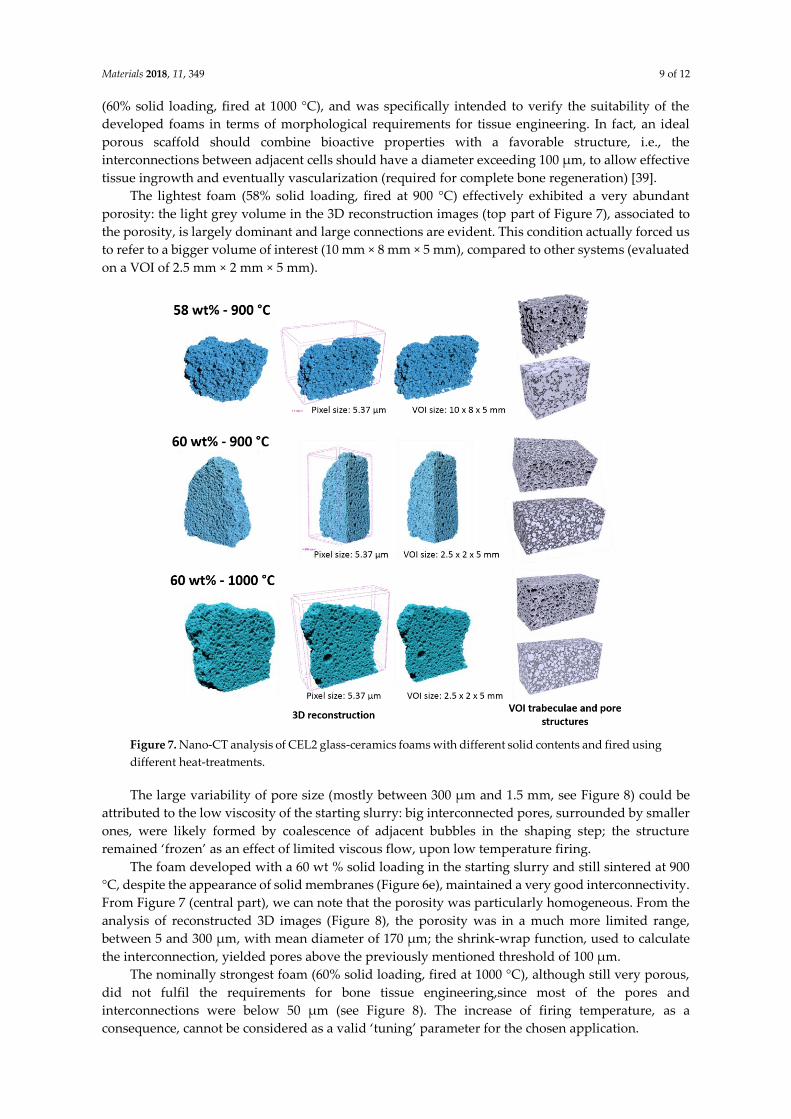
Materials 2018, 11, 349 9 of 12
(60% solid loading, fired at 1000 °C), and was specifically intended to verify the suitability of the
developed foams in terms of morphological requirements for tissue engineering. In fact, an ideal
porous scaffold should combine bioactive properties with a favorable structure, i.e., the
interconnections between adjacent cells should have a diameter exceeding 100 µm, to allow effective
tissue ingrowth and eventually vascularization (required for complete bone regeneration) [39].
The lightest foam (58% solid loading, fired at 900 °C) effectively exhibited a very abundant
porosity: the light grey volume in the 3D reconstruction images (top part of Figure 7), associated to
the porosity, is largely dominant and large connections are evident. This condition actually forced us
to refer to a bigger volume of interest (10 mm × 8 mm × 5 mm), compared to other systems (evaluated
on a VOI of 2.5 mm × 2 mm × 5 mm).
Figure 7. Nano-CT analysis of CEL2 glass-ceramics foams with different solid contents and fired using
different heat-treatments.
The large variability of pore size (mostly between 300 µm and 1.5 mm, see Figure 8) could be
attributed to the low viscosity of the starting slurry: big interconnected pores, surrounded by smaller
ones, were likely formed by coalescence of adjacent bubbles in the shaping step; the structure
remained ‘frozen’ as an effect of limited viscous flow, upon low temperature firing.
The foam developed with a 60 wt % solid loading in the starting slurry and still sintered at 900
°C, despite the appearance of solid membranes (Figure 6e), maintained a very good interconnectivity.
From Figure 7 (central part), we can note that the porosity was particularly homogeneous. From the
analysis of reconstructed 3D images (Figure 8), the porosity was in a much more limited range,
between 5 and 300 µm, with mean diameter of 170 µm; the shrink-wrap function, used to calculate
the interconnection, yielded pores above the previously mentioned threshold of 100 µm.
The nominally strongest foam (60% solid loading, fired at 1000 °C), although still very porous,
did not fulfil the requirements for bone tissue engineering,since most of the pores and
interconnections were below 50 µm (see Figure 8). The increase of firing temperature, as a
consequence, cannot be considered as a valid ‘tuning’ parameter for the chosen application.

Materials 2018, 11, 349 10 of 12
We can conclude that foams sintered at 900 °C may constitute a valid reference for future bone
tissue engineering experiments. The absolute strength (above 5 MPa, for 60% solid loading) and
strength-to-density ratio (especially for 58% solid loading), combined with the optimum pore
distribution, make them good candidates for bone tissue regenerations.
Figure 8. Pore size distribution and interconnectivity of CEL2 glass-ceramic foams, produced by
different solid contents, after heat-treatment.
4. Conclusions
We may conclude that:
• Highly porous CEL2 glass-ceramics can be easily manufactured by ‘inorganic gel-casting’,
followed by sintering with sinter-crystallization; the crystallization limits the viscous flow, so
that the microstructure in the green state is substantially maintained upon firing up to 900–1000
°C;
• The overall foaming process (mechanical stirring of alkali activated suspensions—with the help
of a surfactant, drying, firing with sinter-crystallization) has a great potential for the production
of ‘hierarchically porous’ foams; the microstructure can be tuned operating on simple processing
parameters such solid load, in suspensions, and firing conditions (e.g., heating rate);

Materials 2018, 11, 349 11 of 12
• CEL2 glass-ceramic foams were fabricated, in selected conditions, with very uniform pore size
(mean diameter of 170 µm) and good interconnectivity (well-defined openings are visible
between adjacent cells).
Acknowledgments: Hamada Elsayed gratefully acknowledges the financial support of the Cultural Affairs and
Missions Sector, Egypt. Acacio Rincón Romero and Enrico Bernardo acknowledge the support of the European
Community’s Horizon 2020 Programme through a Marie Skłodowska-Curie Innovative Training Network
(‘CoACH-ETN”, g.a. no. 642557).
Author Contributions: For this paper, Enrico Bernardo and Chiara Vitale Brovarone formulated research ideas,
supervised the experiment on porous CEL2 glass-ceramic materials and planned the structure of the article.
Hamada Elsayed and Acacio Rincón Romero performed the general experimentation except µ-CT
measurements and its data interpretation, which were done by Giulia Molino. Hamada Elsayed and Enrico
Bernardo have written and edited the article.
Conflicts of Interest: The authors declare no conflict of interest.
References
1. Tampieri, A.; Celotti, G.; Landi, E. From biomimetic apatites to biologically inspired composites. Anal.
Bioanal. Chem. 2005, 381, 568–576.
2. Hutmacher, D.W. Scaffolds in tissue engineering bone and cartilage. Biomaterials 2000, 2, 2529–2543.
3. Ramakrishna, S.; Meyer, J.; Wintermantel, E.; Leong, K.W. Biomedical applications of polymer-composite
materials: A review. Comput. Sci. Technol. 2001, 61, 1189–1224.
4. Jones, J.R. Review of bioactive glass: From Hench to hybrids. Acta Biomater. 2013, 9, 4457–4486.
5. Hench, L.L. Bioceramics: From Concept to Clinic. J. Am. Ceram. Soc. 1991, 74, 1487–1510.
6. Kokubo, T.; Takadama, H. How useful is SBF in predicting in vivo bone bioactivity? Biomaterials 2006, 27,
2907–2915.
7. Rabiee, S.M.; Nazparva, N.; Azizian, M.; Vashaee, D.; Tayebi, L. Effect of ion substitution on properties of
bioactive glasses: A review. Ceram. Int. 2015, 41, 7241–7251.
8. Wren, A.W. 45S5 Bioglass Based Scaffolds for Skeletal Repair: Biocompatible Glasses. Adv. Struct. Mater.
2016, 53, 183–201.
9. Kaysinger, K.K.; Ramp, W.K. Extracellular pH modulates the activity of cultured human osteoblasts. J. Cell.
Biochem. 1998, 68, 83–89.
10. El-Ghannam, A.; Ducheyne, P.; Shapiro, I.M. Formation of surface reaction products on bioactive glass and
their effects on the expression of the osteoblastic phenotype and the deposition of mineralized extracellular
matrix. Biomaterials 1997, 18, 295–303.
11. Brandao-Burch, A.; Utting, J.C.; Orriss, I.R.; Arnett, T.R. Acidosis inhibits bone formation by osteoblasts in
vitro by preventing mineralization. Calcif. Tissue Int. 2005, 77, 167–174.
12. Vitale-Brovarone, C.; Verne´, E.; Robiglio, L.; Martinasso, G.; Canuto, R.A.; Muzio, G. Biocompatible glass-
ceramic materials for bone substitution. J. Mater. Sci. Mater. Med. 2008, 19, 471–478.
13. Vitale-Brovarone, C.; Baino, F.; Verne, E. High strength bioactive glass-ceramic scaffolds for bone
regeneration. J. Mater. Sci. Mater. Med. 2009, 20, 643–653.
14. Porter, N.L.; Pilliar, R.M.; Grynpas, M.D. A review of materials, fabrication methods, and strategies used
to enhance bone regeneration in engineered bone tissues. J. Biomed. Mater. Res. 2001, 56, 504–515.
15. Vitale-Brovarone, C.; Verné, E.; Robiglio, L.; Appendino, P.; Bassi, F.; Martinasso, G.; Muzio, G.; Canuto, R.
Development of glass-ceramic scaffolds for bone tissue engineering: Characterisation, proliferation of
human osteoblasts and nodule formation. Acta Biomater. 2007, 3, 199–208.
16. Vitale-Brovarone, C.; Miola, M.; Balagna, C.; Verné, E. 3D-glass–ceramic scaffolds with antibacterial
properties for bone grafting. Chem. Eng. J. 2008, 137, 129–136.
17. Lyckfeldt, O.; Ferreira, J.M. Processing of porous ceramics by starch consolidation. J. Eur. Ceram. Soc. 1998,
18, 131–140.
18. Vitale-Brovarone, C.; Di Nunzio, S.; Bretcanu, O.; Vernné, E. Macroporous glass-ceramic materials with
bioactive properties. J. Mater. Sci. Mater. Med. 2004, 15, 209–217.
19. Vitale-Brovarone, C.; Verné, E.; Appendino, P. Macroporous bioactive glass-ceramic scaffolds for tissue
engineering. J. Mater. Sci. Mater. Med. 2006, 17, 1069–1078.

Materials 2018, 11, 349 12 of 12
20. Baino, F.; Ferraris, M.; Bretcanu, O.; Verné, E.; Vitale-Brovarone, C. Optimization of composition, structure
and mechanical strength of bioactive 3-D glass-ceramic scaffolds for bone substitution. J. Appl. Biomater.
2013, 27, 872–890.
21. Rincón, A.; Giacomello, G.; Pasetto, M.; Bernardo, E. Novel ‘inorganic gel casting’ process for the
manufacturing of glass foams. J. Eur. Ceram. Soc. 2017, 37, 2227–2234.
22. Elsayed, H.; Rincón Romero, A.; Ferroni, L.; Gardin, C.; Zavan, B.; Bernardo, E. Bioactive Glass-Ceramic
Scaffolds from Novel ‘Inorganic Gel Casting’ and Sinter-Crystallization. Materials 2017, 10, 171.
23. Wang, X.; Ruan, J.; Chen, Q. Effects of surfactants on the microstructure of porous ceramic scaffolds
fabricated by foaming for bone tissue engineering. Mater. Res. Bull. 2009, 44, 1275–1279.
24. Rincon Romero, A.; Elsayed, H.; Bernardo, E. Highly porous mullite ceramics from engineered alkali
activated suspensions. J. Am. Ceram. Soc. 2018, 101, 1036–1041.
25. Provis, J.L. Geopolymers and other alkali activated materials: Why, how, and what? Mater. Struct. 2014, 47,
11–25.
26. Shah, A.T.; Batool, M.; Chaudhry, A.A.; Iqbal, F.; Javaid, A.; Zahid, S.; Ilyas, K.; Bin Qasim, S.; Khan, A.F.;
Khan, A.S.; et al. Effect of calcium hydroxide on mechanical strength and biological properties of bioactive
glass. J. Mech. Behav. Biomed. Mater. 2016, 61, 617–626.
27. Chakradhar, R.S.; Nagabhushana, B.M.; Chandrappa, G.T.; Ramesh, K.P.; Rao, J.L. Solution combustion
derived nanocrystalline macroporous wollastonite ceramics. Mater. Chem. Phys. 2006, 95, 169–175.
28. Zhang, Q.; Ye, G. Dehydration kinetics of Portland cement paste at high temperature. J. Therm. Anal.
Calorim. 2012, 110, 153–158.
29. Watanabe, T.; Hashimoto, H.; Hayashi, M.; Nagata, K. Effect of Alkali Oxides on Crystallization in CaO–
SiO2–CaF2 Glasses. ISIJ Int. 2008, 48, 925–933.
30. Hemmings, R.; Berry, E. On the glass in coal fly ashes: Recent advances. In MRS Proceedings; Cambridge
Univ Press: Cambridge, UK, 1987; p. 3.
31. Wu, C.; Chang, J. A review of bioactive silicate ceramic. Biomed. Mater. 2013, 8, 032001.
32. Mohammadi, H.; Sepantafar, M.; Ostadrahimi, A. The Role of Bioinorganics in Improving the Mechanical
Properties of Silicate Ceramics as Bone Regenerative Materials. J. Ceram. Sci. Tech. 2015, 6, 1–8.
33. Thompson, I.D.; Hench, L.L. Mechanical Properties of Bioactive Glasses, Glass-Ceramics and Composites.
Proc. Inst. Mech. Eng. Part H. J. Eng. Med. 1998, 212, 127–136.
34. Rahaman, M.N.; Liu, X.; Huang, T.S. Bioactive glass scaffolds for the repair of load-bearing bones. In
Advances in Bioceramics and Porous Ceramics; Narayan, R., Colombo, P., Eds.; John Wiley & Sons: Hoboken,
NJ, USA, 2009; Volume 32, pp. 65–78.
35. Gibson, L.J.; Ashby, M.F. Cellular Solids, Structure and Properties, 2nd ed.; Cambridge University Press:
Cambridge, UK, 1999.
36. Höland, W., Beall, G. Glass-Ceramic Technology; The American Ceramic Society: Westerville, OH, USA, 2002.
37. Rice, R. Porosity of Ceramic; Marcel Dekker, Inc.: New York, NY, USA, 1998.
38. Rice, R. Mechanical Properties. In Cellular Ceramics: Structure, Manufacturing, Properties and Applications;
Scheffler, M., Colombo, P., Eds.; WILEY-VCH Verlag GmbH: Weinheim, Germany, 2005; pp. 291–312.
39. Hulbert, S.F.; Morrison, S.J.; Klawitter, J.J. Tissue reaction to three ceramics of porous and non-porous
structures. J. Biomed. Mater. Res. 1972, 6, 347–374.
© 2018 by the authors. Licensee MDPI, Basel, Switzerland. This article is an open access
article distributed under the terms and conditions of the Creative Commons Attribution
(CC BY) license (http://creativecommons.org/licenses/by/4.0/).