Innovation in target fabrication can reduce cost, schedule and risk of ignition and compensate for...
19
Innovation in target fabrication can reduce cost, schedule and risk of ignition and compensate for driver inflexibility US Japan IFE Workshop 3-22-05 Joe Kilkenny General Atomics
-
date post
20-Dec-2015 -
Category
Documents
-
view
213 -
download
0
Transcript of Innovation in target fabrication can reduce cost, schedule and risk of ignition and compensate for...

Innovation in target fabrication can reduce cost, schedule and risk of ignition and compensate for
driver inflexibility
US Japan IFE Workshop
3-22-05
Joe Kilkenny
General Atomics

Success inHEDP, and Ignition requires-
There has been inadequate investment in target fabrication S&T commensurate with its role in the SS Program
• Drivers -major investment
Z-ROMEGA EP & Nike,Trident,..NIF
•Simulations, ASCI -major investment
•Target S&T -Cinderella~$25M FY 04
3D rad.-hydro Simulation of igniting target
Double shelltarget

3D codes allow sophisticated 3D targets, reduce risk, cost and schedule & compensate for driver limitations
• Hohlraums-gas fill reduces symmetry swings
• Cocktail hohlraum wall reduce x-ray wall loss-helps all drivers
• Graded doped ablators reduce instability,allow fill tubes&
reduce cryo cost for NIF ignition target
Innovation in target fabrication compensates for driver and facilty limitations
thin(0.1m) windows
Convection -- Bafflesor
low foams
Innovation in target fabrication: gas fill in Hohlraums provides symmetry control-Compensates for driver inflexibility
Target fabrication challenges remain!
Gas fillReduces wallMotionBUT

Target fabrication and characterizationDrives target choices
•Beryllium is the best ablator-
• But Be has fabrication and characterization issues:- surface finish - filling - no augmented beta layering-characterization difficult- opaque
The first choice NIF ignition target was diffusion filled plastic with fewer target fab. issues

The NIF baseline target was plastic diffusion filled
•Baseline target-diffusion fill- Physics issues
-surface finish-augmented layering-Optical characterization
BUT
• $ and schedule issues with The NIF cryogenic target handling system because diffusion fill/cold transport
(1)&(2)
(3)
(4)&(5) (6)&(7)
(8)
(9)
Target Cryostat
Target Transporter
Fill Cryostat
Layering and Characterization Station
Shroud
Target Chamber
Retractor
Inserter
Refurbishment
The large number of cryo. sub-systems increases complexity & cost

A 10 year ~ $30M GA & LLE effort was required for the OMEGA diffusion & cold fill cryo system: NIF prototype
Tritium use late 2004?
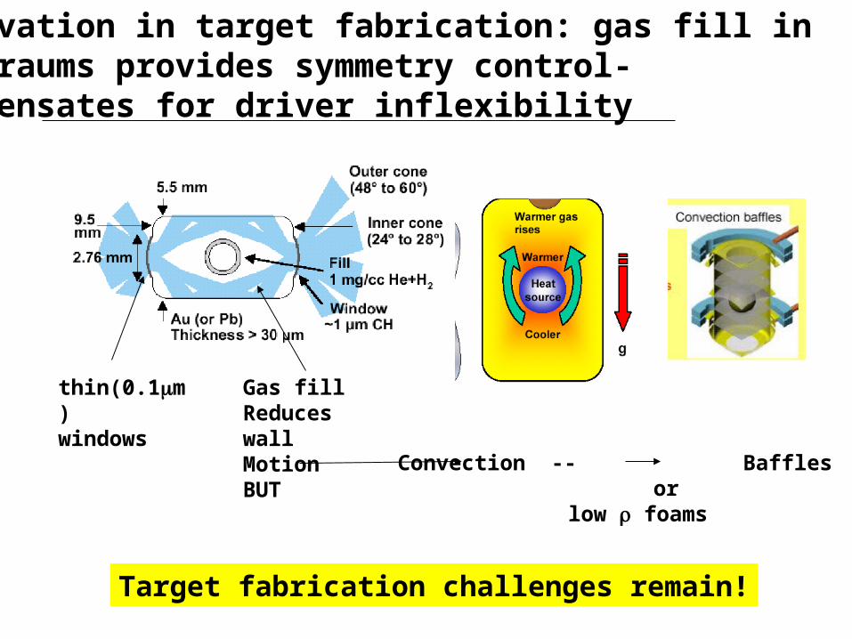
Innovation in target fabrication: graded dopant Be shells less unstable & may allow a fill tube
Filling in situ reduces the cost of the NIF cryo system
Graded Cu dopantIn Be shell
Is less UnstableHow much less?
A small fill tube mayNot cause too largeA perturbation:

Dopants in the ablators are required to reduce x-ray preheat at the ablator-ice interface
•X-ray preheat at ice-ablator interface heats absorbed by ablator not by ice•This makes ablator less compressible than DT ice•Can lead to a hydrodynamically unstable interface
AblatorDT ice
radius
w/o dopant
radius
w/ uniform dopant
Reducing x-ray preheat can reduce density jump (Atwood number) at interface
But:Shorter ablation scalelengthLower mass ablation rate

0.35%0.7%
0.35%
848
928
1105 µm
934940 995
1011
0.0%
Cu(%)
300 eV design:
200
Initial ablator roughness (rms, nm)
0
5
10
15
20
25
Yield(MJ)
Polyimide capsule
Surface achieved with PI
400 600 8000
300 eV graded-dopedBe(Cu) design, at same
scale
Innovations in target fabrication using Be with graded Cu dopant provide much more stability margin
Be
DT
0.0%
But can the targets be made and then characterizedTo the required precise specifications?

Be and CH are both potential ablator materials for ignition capsules
Physics Issues Fabrication Issues
Dopant gradient flexibility
Fill tube/Fill hole
Be CH
Hohlraum layering (conductivity)
Surface finish
Morphology (internal structure)
Characterization
Enhanced -layering (DD and layer temp)
0 +
0/– +
0/+ 0/–
0/– +
0 0/+
– 0/+
0/+ 0
Absorption Efficiency (density/opacity)
Stability
Fill tube tolerance
Drive temperature range
Morphology effects
Be CH
+ 0
+ 0
+ 0/–
+ 0/–
0/– +
Be capsules are preferred for physics performance but present greater fabrication challenges
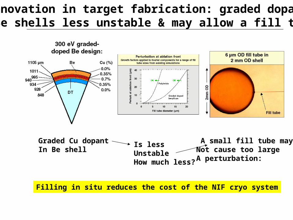
Hohlraum Energetics
10-20% of the laser energy to capsule
1.00.9.7650.4250.200.1414%
1.21.080.920.580.200.1411.7%
Laser light (MJ) Absorbed Xrays Wall loss Hole loss Capsule Efficiency (%)
1.451.301.100.680.280.149.7%
Au with CH Capsule
Au with Be Capsule
Cocktails - Be Capsule
The Indirect Drive Ignition point design continuesto evolve to optimize coupling efficiency
Cocktails, LEH shields -Be Capsule
0.85 0.77 0.655 0.295 0.220 0.14 16.5%

Glass tube, 17 µm OD, 5 µm ID, inserted 20 µm, with 5 µm diameter hole through beryllium ablator
Be
DT
Ignition
Simulations indicate that a 10-20 µm diameter tube will have an acceptable impact on the implosion
• Graded doped 200 kJ Be(Cu) capsule
• Calculation ignites and burns with near 1D yields
• Graded doped Be capsules are best but simulations carried out with uniformly doped Be, and graded doped CH capsules all give near 1D yields with 10 micron diameter tubes.
Target Fabrication
Update with point design scale info

New capsule provides new opportunities but also presents major fabrication challenges
Be sputtertargets
Bounce pan
Piezoelectricoscillator
Cu sputtertarget
CH mandrels
voltagebias
VacuumChamber
20 µm
400 nm
Cross-section of 100 m thick shell
Uniform copperDistribution by TEM
Tiny holes have been laser drilled for filling
2 µm Entrance
1 m
Sub-micron grains
Cu-doped Be capsules are made by sputter deposition onto CH mandrels in a bounce pan

We can attach ~ 6 µm fill tubes to capsulesbut with too large a perturbation so far
2mm
OD
6µm OD fill tube, 2mm OD shell
Epoxy
6µm OD
Fill tube
Target fabrication issues : too large a perturbation by the glue

Key fabrication capabilities for fill-tubes are being developed and demonstrated
The glue layer is ~ 1µm thick
10 µm Glass Tube in Al Flat Laser Drilling in Be
Entrance
Exit2 µm
Laser: Ti:sapphire405 nm, <1 µJ, 120 fs, 3.5 kHz drilling time: ~40 sec
2 µm
Target Fabrication

The 2010 ignition plan has risk mitigation options for the key features of the point design target
Capsule fill method
Risk mitigationoptions
Fill Tube Diffusion Fill (CH)
Point Design(Risk)
(Low/moderate)
Impact of Failure
Ablator MaterialBe
CH(Low/moderate)
1.2 to 1.45 MJ (20%)
Hohlraum material Cocktail Au(Low)
1.0 to 1.2 MJ (20%)
Hohlraum geometryIncludes LEH shields
No LEH shields(Low)
0.85 to 1.0 MJ (17%)
Hohlraum low-z fillSiO2 foam (for operational simplicity and flexibility)
He/H gas fill
SiO2, Be, or Ni solid liner (with prepulse to eliminate hydro coupling)
(Low/moderate)
(Scattering could increase from 10% to 30%)
1.45 to 1.7 MJ (20%)
More complex cryo system

Nano technology methods can be used for monolithic fill tube manufacture
~ 5 micron mandrel grown withlaser CVD on Be spherein a laser drilled hole
Be or Borontube is grown offof the sphereand surrounding the mandrel
also by laser CVD
Mandrel is dissolved
leaving fill tube 6m