Innovation in soft start technology - Fairford · Innovation in soft start technology agility QUICK...
20
Innovation in soft start technology agility QUICK START GUIDE MAN-AGY-002. Version 01
Transcript of Innovation in soft start technology - Fairford · Innovation in soft start technology agility QUICK...

Innovation in soft start technology
agility QUICK START GUIDE
MAN-AGY-002. Version 01

1 1
agility Series Quick Start Guide
MAN-AGY-002. Version 01. 12/06/2017
agility Quick Start Guide
Fairford Electronics Ltd
Bristow House
Gillard Way, Ivybridge
PL21 9GG
UK
www.fairford.com
[Full User Manual (MAN-AGY-001) available from www.fairford.com]
© 2017 by Fairford Electronics, all rights reserved
Copyright subsists in all Fairford Electronics deliverables including magnetic, optical and/or any
other soft copy of these deliverables. This document may not be reproduced, in full or in part,
without written permission. Enquiries about copyright of Fairford Electronics deliverables should
be made to Fairford Electronics Ltd. If, by permission of the copyright owner, any part of this
document is quoted, then a statement specifying the original document shall be added to the
quotation. Any such quotation shall be according to the original (text, figure or table) and may
not be shortened or modified.
2 2
agility Series Quick Start Guide
MAN-AGY-002. Version 01. 12/06/2017
Important information
Installers should read and understand the instructions in this guide prior to installing, operating
and maintaining the soft start. The following symbols may appear in this guide or on the soft
start to warn of potential hazards or to draw attention to certain information.
Dangerous Voltage
Indicates the presence of a hazardous voltage which could result in personal injury or death.
Warning/Caution
Indicates a potential hazard. Any instructions that follow this symbol should be obeyed to avoid
possible damage to the equipment, and personal injury or death.
Protective Earth (Ground) Indicates a terminal which is intended for connection to an external conductor for protection
against electric shock in case of a fault.
Caution Statements
The examples and diagrams in this manual are included solely for illustrative purposes. The
information contained in this manual is subject to change at any time and without prior notice.
In no event will responsibility or liability be accepted for direct, indirect or consequential
damages resulting from the use or application of this equipment.
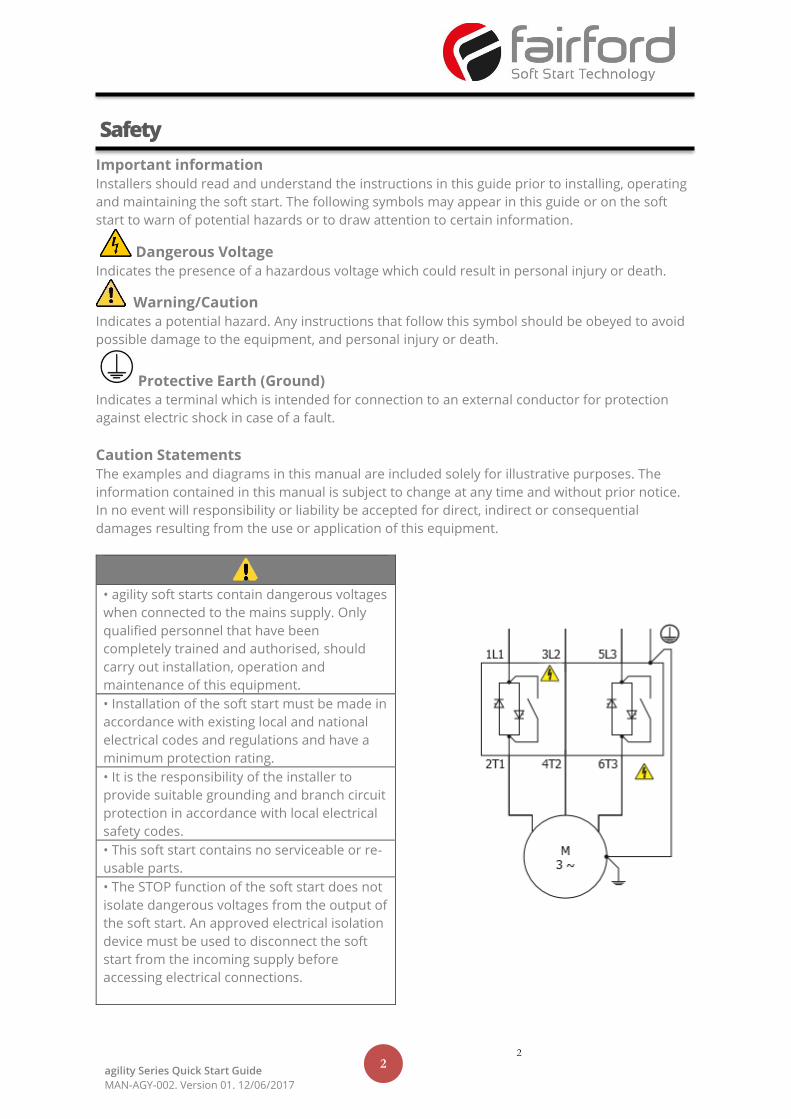
• agility soft starts contain dangerous voltages
when connected to the mains supply. Only
qualified personnel that have been
completely trained and authorised, should
carry out installation, operation and
maintenance of this equipment.
• Installation of the soft start must be made in
accordance with existing local and national
electrical codes and regulations and have a
minimum protection rating.
• It is the responsibility of the installer to
provide suitable grounding and branch circuit
protection in accordance with local electrical
safety codes.
• This soft start contains no serviceable or re-
usable parts.
• The STOP function of the soft start does not
isolate dangerous voltages from the output of
the soft start. An approved electrical isolation
device must be used to disconnect the soft
start from the incoming supply before
accessing electrical connections.
Safety
3 3
agility Series Quick Start Guide
MAN-AGY-002. Version 01. 12/06/2017
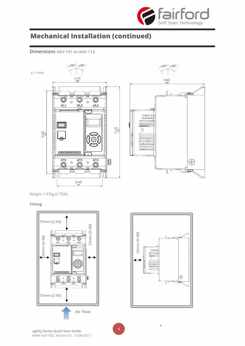
Mounting
Fix the unit to a flat, vertical surface using the mounting holes (or slots) on its base-plate. The
mechanical outline diagrams, shown on Page 4, give the dimensions and mounting hole
positions for each model. Ensure that:
• The orientation of the unit has the ‘TOP’ uppermost.
• The location allows adequate front access.
• You can view the touchscreen.
Do not install other equipment that generates significant heat close to the soft starter.
Requirements for an Enclosure
For a typical industrial environment, an enclosure would provide the following:
• A single location for the unit and its protection/isolation switch-gear.
• The safe termination of cabling and/or bus-bars.
• Means to effect proper air flow through the enclosure.
Enclosure Ventilation When fitting agility into a cabinet, ventilation must be provided. The heat dissipated can be
approximated with the formula:-
Starting
Watts (agility) = start current(A) x start time(s) x number of starts per hour/ 1800
Running
Watts(agility) = 0.4 x running amps
Use the following formula to determine the fan requirement. An allowance has been incorporated into
the formula so that the figure for Q is the air delivery in the fan suppliers data.
Q = (4 x Wt / (Tmax-Tamb))
Q = volume of air (cubic metres per hour-m3/h)
Wt = Heat produced by the unit and all other heat sources within the enclosure (Watts) Tmax
= Maximum permissible temperature within the enclosure (40°C for a fully rated agility™)
Tamb = Temperature of the air entering the enclosure (°C) [to work in CFM, substitute °F for
°C. Q is now in CFM]
Altitude Derate Altitude above sea level 1000m (3281ft). Above 1000m de rate by 1% of agility i.e. per 100m
(328ft) to a maximum altitude of 2000m (6562ft)
Ambient Temperature Derate
-20°C (-4°F) to 40°C (122°F). Above 40°C de-rate linearly by 2% of agility i.e. per °C to a maximum
of 60°C (140°F).
Mechanical Installation
4 4
agility Series Quick Start Guide
MAN-AGY-002. Version 01. 12/06/2017
Dimensions AGY-101 to AGY-113
Weight 1.97kg (3.75lb)
Fitting
Mechanical Installation (continued)
Air Flow
[ ] = inch
5 5
agility Series Quick Start Guide
MAN-AGY-002. Version 01. 12/06/2017
Warnings
Isolation
Caution: agility uses semiconductor devices in the main circuit and is not designed to
provide isolation. For this reason isolation means must be installed in the supply circuit in
accordance with the appropriate wiring and safety regulations
Electrical Control Supply Requirements
All electrical connections are made to power input and output terminals, control terminals
and an earth stud .
Fuse Protection
The Mains Supply and the Control Supply each require protection. Although all units have
electronic overload protection for the Soft Start, the installer should always fit fuses, for
motor protection, between the unit and the Mains Supply, not between the unit and the motor.
Semiconductor fuses can be supplied as an option for short-circuit protection of the
semiconductors. These fuses must be fitted externally to the agility chassis to comply with certain
standards. It is the responsibility of the installer and system designer/specifier to ensure that the
required standards or regulations are not affected by so doing.
Safety
agility soft starters contain hazardous voltages when connected to the electrical power
supply. Only qualified personnel who are trained and authorized should carry out
installation, operation and maintenance of this equipment. Refer to and carefully follow all
of the ‘Warnings’ section at the begining of this user manual, as well as other warnings and notes
throughout the manual.
Electrical Supplies
The unit requires a 3-phase balanced Mains Supply to provide the power for the controlled motor,
and a 24Vdc for the internal control circuitry. The unit will not operate unless the control supply
voltage is within the specified limits.
Electrical Installation
6 6
agility Series Quick Start Guide
MAN-AGY-002. Version 01. 12/06/2017
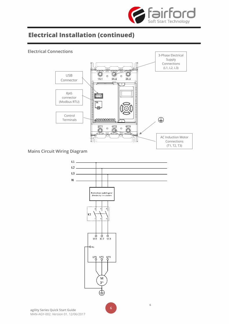
Electrical Connections
Mains Circuit Wiring Diagram
Electrical Installation (continued)
3-Phase Electrical
Supply
Connections
(L1, L2, L3)
RJ45
connector
(Modbus RTU)
USB
Connector
Control
Terminals
AC Induction Motor
Connections
(T1, T2, T3)
7 7
agility Series Quick Start Guide
MAN-AGY-002. Version 01. 12/06/2017
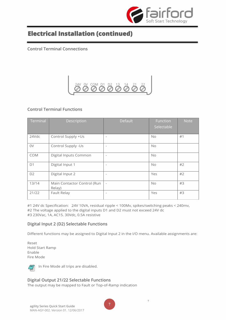
Control Terminal Connections
Control Terminal Functions
#1 24V dc Specification: 24V 10VA, residual ripple < 100Mv, spikes/switching peaks < 240mv,
#2 The voltage applied to the digital inputs D1 and D2 must not exceed 24V dc
#3 230Vac, 1A, AC15. 30Vdc, 0.5A resistive
Digital Input 2 (D2) Selectable Functions
Different functions may be assigned to Digital Input 2 in the I/O menu. Available assignments are:
Reset
Hold Start Ramp
Enable
Fire Mode
In Fire Mode all trips are disabled.
Digital Output 21/22 Selectable Functions The output may be mapped to Fault or Top-of-Ramp indication
Terminal Description Default Function
Selectable
Note
24Vdc Control Supply +Us - No #1
0V Control Supply -Us - No
COM Digital Inputs Common - No
D1 Digital Input 1 - No #2
D2 Digital Input 2 - Yes #2
13/14 Main Contactor Control (Run
Relay)
- No #3
21/22 Fault Relay - Yes #3
Electrical Installation (continued)
24V COM 0V 13 D1 14 D2 22 21
8 8
agility Series Quick Start Guide
MAN-AGY-002. Version 01. 12/06/2017
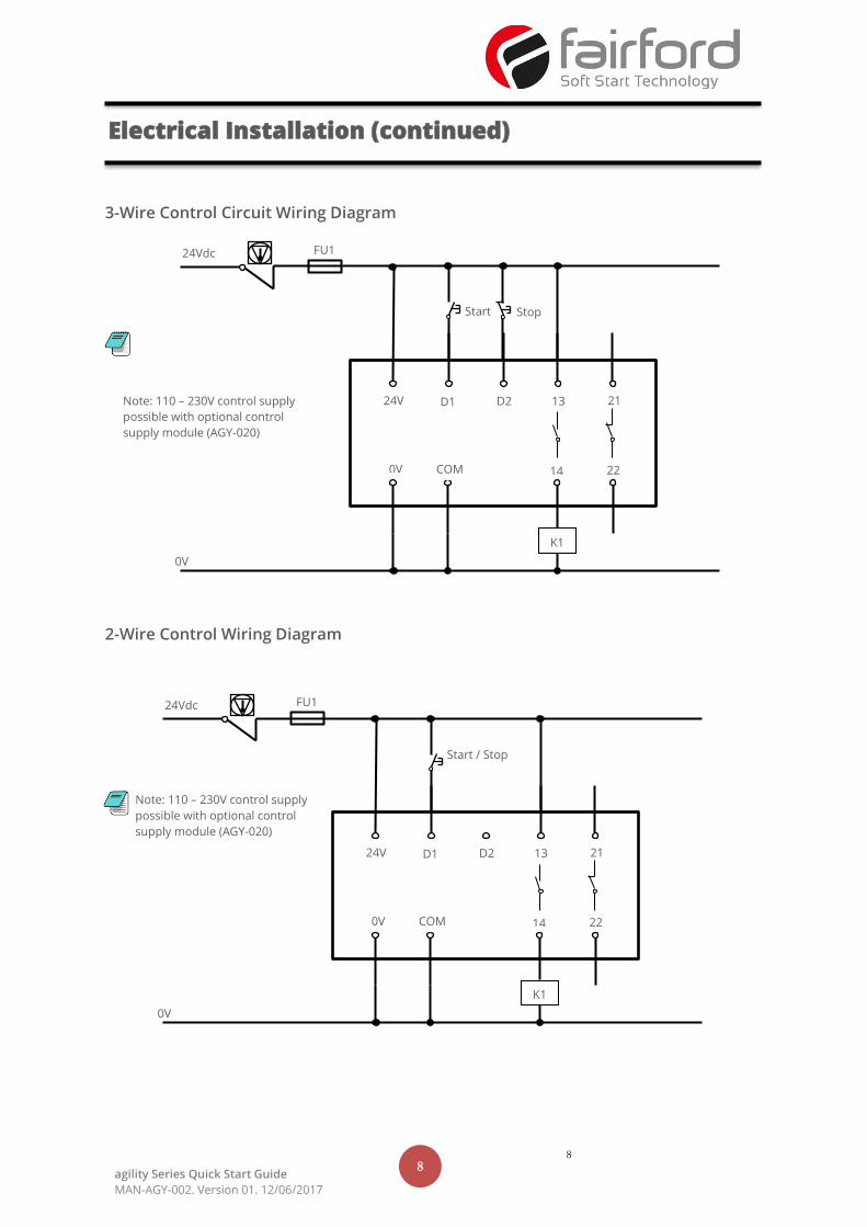
3-Wire Control Circuit Wiring Diagram
2-Wire Control Wiring Diagram
K1
0V
Start Stop
24V D1 D2 13
0V COM 14
21
22
FU1 24Vdc
Note: 110 – 230V control supply
possible with optional control
supply module (AGY-020)
K1
0V
Start / Stop
24V D1 D2 13
0V COM 14
21
22
FU1 24Vdc
Note: 110 – 230V control supply
possible with optional control
supply module (AGY-020)
Electrical Installation (continued)
9 9
agility Series Quick Start Guide
MAN-AGY-002. Version 01. 12/06/2017
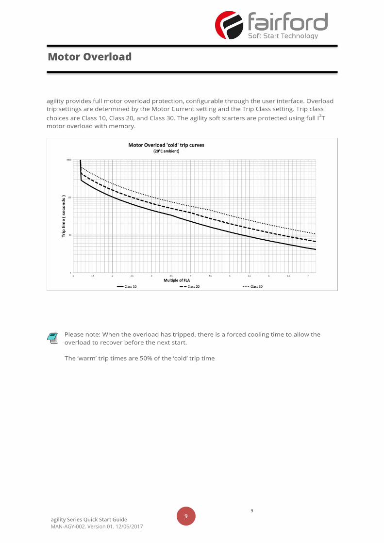
agility provides full motor overload protection, configurable through the user interface. Overload
trip settings are determined by the Motor Current setting and the Trip Class setting. Trip class
choices are Class 10, Class 20, and Class 30. The agility soft starters are protected using full I2T
motor overload with memory.
Please note: When the overload has tripped, there is a forced cooling time to allow the
overload to recover before the next start.
The ‘warm’ trip times are 50% of the ‘cold’ trip time
Motor Overload
10 10
agility Series Quick Start Guide
MAN-AGY-002. Version 01. 12/06/2017
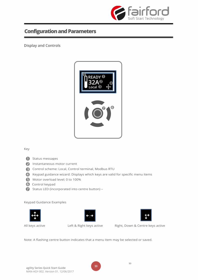
Display and Controls
Key
Keypad Guidance Examples
All keys active Left & Right keys active Right, Down & Centre keys active
Note: A flashing centre button indicates that a menu item may be selected or saved.
Configuration and Parameters
Local
Status messages
Instantaneous motor current
Control scheme: Local, Control terminal, Modbus RTU
Motor overload level; 0 to 100%
Keypad guidance wizard: Displays which keys are valid for specific menu items
Status LED (incorporated into centre button) –
Green/Red
READY
32A Local
Control keypad
11 11
agility Series Quick Start Guide
MAN-AGY-002. Version 01. 12/06/2017
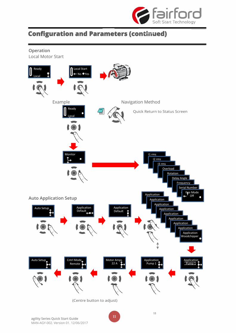
Operation
Local Motor Start
Example Navigation Method
Auto Application Setup
Configuration and Parameters (continued)
Ready
Local
Monitor I1 rms 30A I2 rms
30A I3 rms 30A Overload
30A Rotation Delay Angle
Frequency Serial Number
A1234567 Fire Mode Off
Ready
Local
Local Start No Yes
Quick Return to Status Screen
Auto Setup Application Default
Application Default
30A
30A
30A
30A
Application
Application
Application
Application
Application
Application
[x24]
Application
Application
Application Woodchipper
Application Pump 1
Application Pump 1
Motor Amps 22 A
Cntrl Mode
Remote
Auto Setup
12 agility Series Quick Start Guide
MAN-AGY-002. Version 01. 31/05/2017
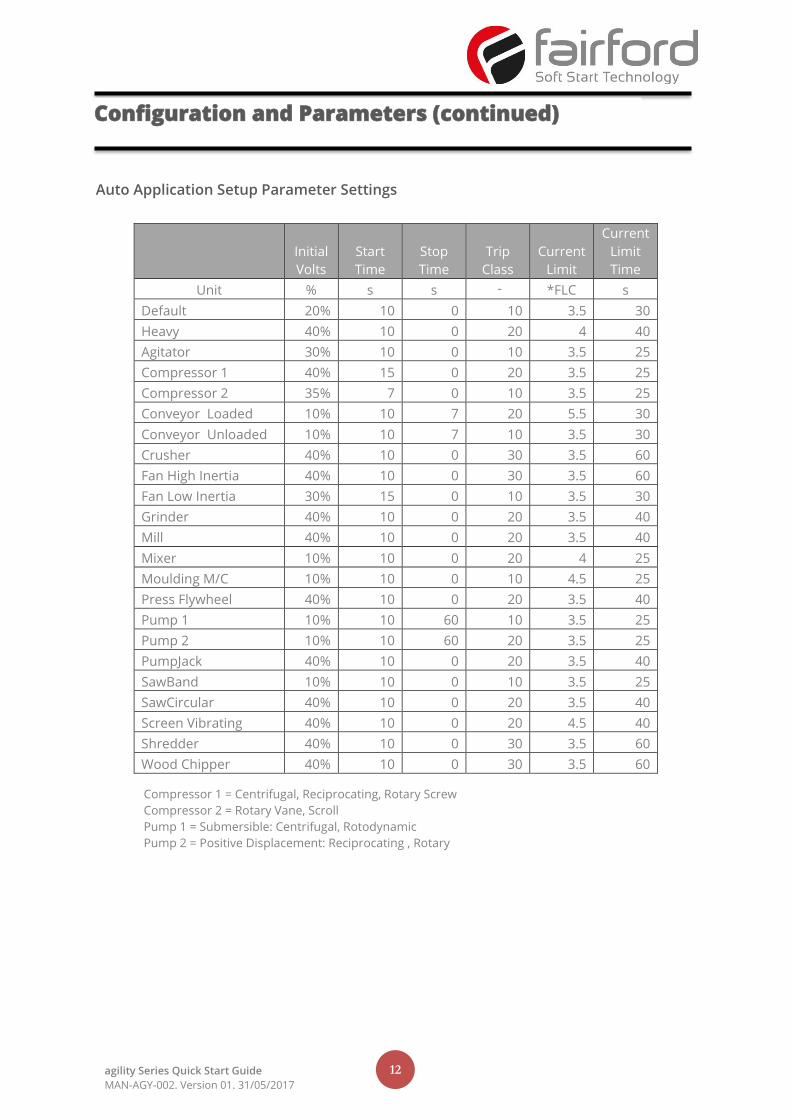
Auto Application Setup Parameter Settings
Initial
Volts
Start
Time
Stop
Time
Trip
Class
Current
Limit
Current
Limit
Time
Unit % s s - *FLC s
Default 20% 10 0 10 3.5 30
Heavy 40% 10 0 20 4 40
Agitator 30% 10 0 10 3.5 25
Compressor 1 40% 15 0 20 3.5 25
Compressor 2 35% 7 0 10 3.5 25
Conveyor Loaded 10% 10 7 20 5.5 30
Conveyor Unloaded 10% 10 7 10 3.5 30
Crusher 40% 10 0 30 3.5 60
Fan High Inertia 40% 10 0 30 3.5 60
Fan Low Inertia 30% 15 0 10 3.5 30
Grinder 40% 10 0 20 3.5 40
Mill 40% 10 0 20 3.5 40
Mixer 10% 10 0 20 4 25
Moulding M/C 10% 10 0 10 4.5 25
Press Flywheel 40% 10 0 20 3.5 40
Pump 1 10% 10 60 10 3.5 25
Pump 2 10% 10 60 20 3.5 25
PumpJack 40% 10 0 20 3.5 40
SawBand 10% 10 0 10 3.5 25
SawCircular 40% 10 0 20 3.5 40
Screen Vibrating 40% 10 0 20 4.5 40
Shredder 40% 10 0 30 3.5 60
Wood Chipper 40% 10 0 30 3.5 60
Compressor 1 = Centrifugal, Reciprocating, Rotary Screw
Compressor 2 = Rotary Vane, Scroll
Pump 1 = Submersible: Centrifugal, Rotodynamic
Pump 2 = Positive Displacement: Reciprocating , Rotary
Configuration and Parameters (continued)
13 agility Series Quick Start Guide
MAN-AGY-002. Version 01. 31/05/2017
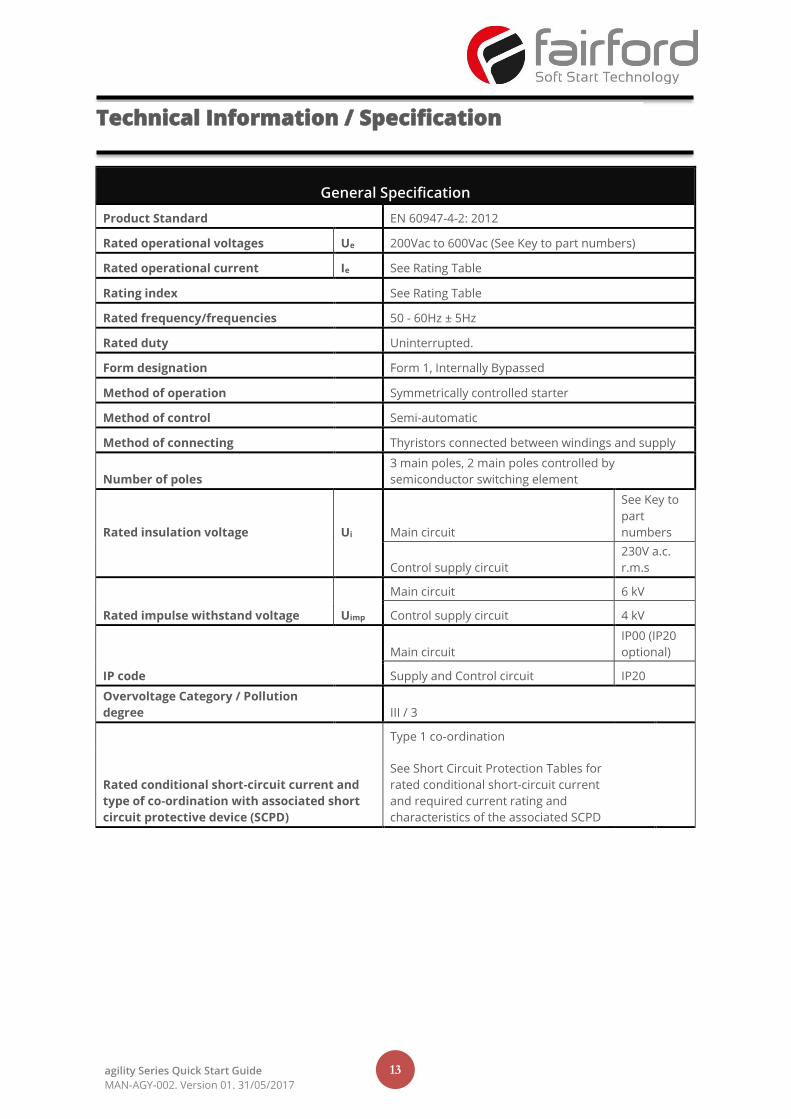
General Specification
Product Standard EN 60947-4-2: 2012
Rated operational voltages Ue 200Vac to 600Vac (See Key to part numbers)
Rated operational current Ie See Rating Table
Rating index See Rating Table
Rated frequency/frequencies 50 - 60Hz ± 5Hz
Rated duty Uninterrupted.
Form designation Form 1, Internally Bypassed
Method of operation Symmetrically controlled starter
Method of control Semi-automatic
Method of connecting Thyristors connected between windings and supply
Number of poles
3 main poles, 2 main poles controlled by
semiconductor switching element
Rated insulation voltage Ui Main circuit
See Key to
part
numbers
Control supply circuit
230V a.c.
r.m.s
Rated impulse withstand voltage Uimp
Main circuit 6 kV
Control supply circuit 4 kV
IP code
Main circuit
IP00 (IP20
optional)
Supply and Control circuit IP20
Overvoltage Category / Pollution
degree III / 3
Rated conditional short-circuit current and
type of co-ordination with associated short
circuit protective device (SCPD)
Type 1 co-ordination
See Short Circuit Protection Tables for
rated conditional short-circuit current
and required current rating and
characteristics of the associated SCPD
Technical Information / Specification
14 agility Series Quick Start Guide
MAN-AGY-002. Version 01. 31/05/2017
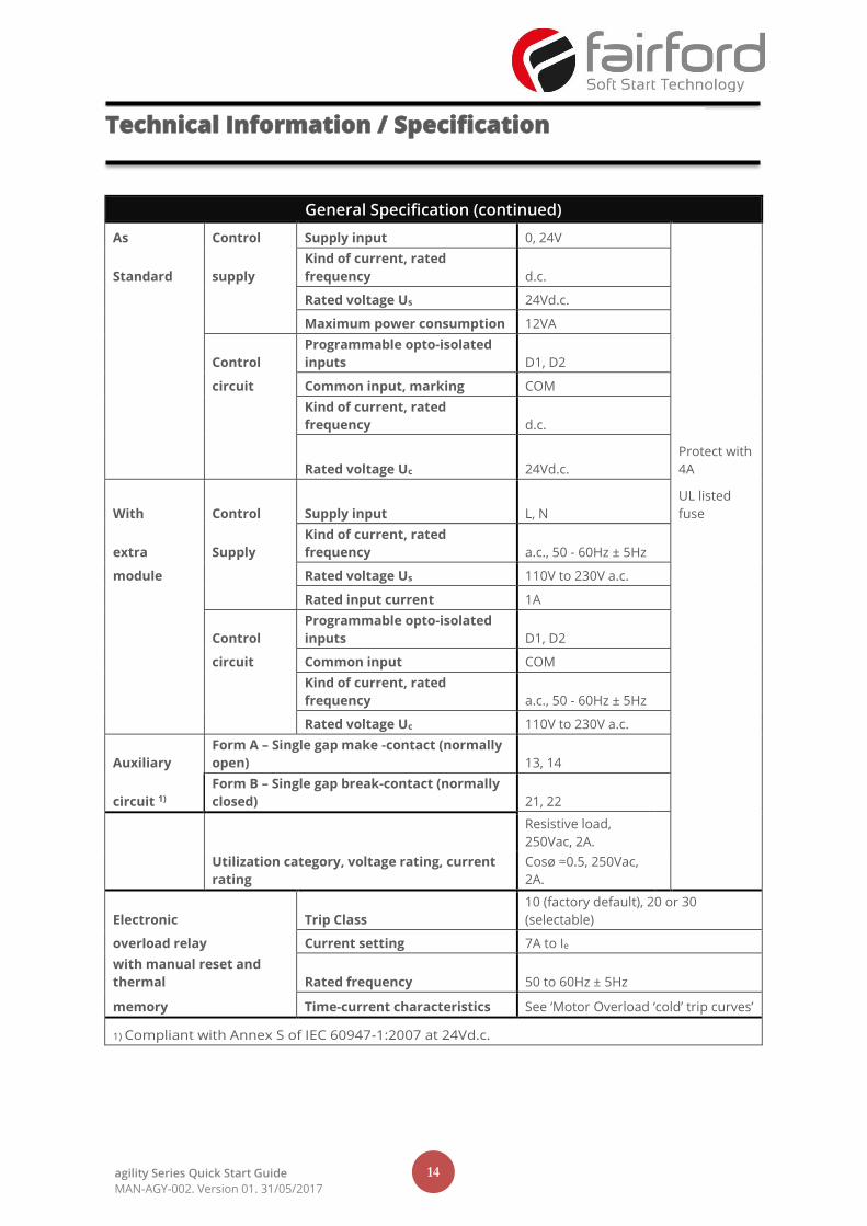
General Specification (continued)
As Control Supply input 0, 24V
Standard supply
Kind of current, rated
frequency d.c.
Rated voltage Us 24Vd.c.
Maximum power consumption 12VA
Control
Programmable opto-isolated
inputs D1, D2
circuit Common input, marking COM
Kind of current, rated
frequency d.c.
Rated voltage Uc 24Vd.c.
Protect with
4A
With Control Supply input L, N
UL listed
fuse
extra Supply
Kind of current, rated
frequency a.c., 50 - 60Hz ± 5Hz
module Rated voltage Us 110V to 230V a.c.
Rated input current 1A
Control
Programmable opto-isolated
inputs D1, D2
circuit Common input COM
Kind of current, rated
frequency a.c., 50 - 60Hz ± 5Hz
Rated voltage Uc 110V to 230V a.c.
Auxiliary
Form A – Single gap make -contact (normally
open) 13, 14
circuit 1)
Form B – Single gap break-contact (normally
closed) 21, 22
Utilization category, voltage rating, current
rating
Resistive load,
250Vac, 2A.
Cosø =0.5, 250Vac,
2A.
Electronic Trip Class
10 (factory default), 20 or 30
(selectable)
overload relay Current setting 7A to Ie
with manual reset and
thermal Rated frequency 50 to 60Hz ± 5Hz
memory Time-current characteristics See ‘Motor Overload ‘cold’ trip curves’
1) Compliant with Annex S of IEC 60947-1:2007 at 24Vd.c.
Technical Information / Specification
15 agility Series Quick Start Guide
MAN-AGY-002. Version 01. 31/05/2017
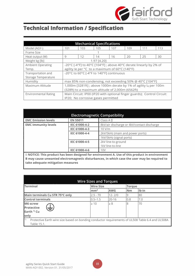
Electromagnetic Compatibility
EMC Emission levels EN 55011 Class A
EMC Immunity levels IEC 61000-4-2 8kV/air discharge or 4kV/contact discharge
IEC 61000-4-3 10 V/m
IEC 61000-4-4 2kV/5kHz (main and power ports)
1kV/5kHz (signal ports)
IEC 61000-4-5 2kV line-to-ground
1kV line-to-line
IEC 61000-4-6 10V
NOTICE: This product has been designed for environment A. Use of this product in environment
B may cause unwanted electromagnetic disturbances, in which case the user may be required to
take adequate mitigation measures
Mechanical Specifications Model (AGY-) 101 103 105 107 109 111 113
Frame Size 1
Heat output (W) 9 12 14 16 20 25 30
Weight kg [lb] 1.97 [4.20]
Ambient Operating
Temp.
-20°C [-4°F] to 40°C [104°F] ; above 40°C derate linearly by 2% of
agility Ie per °C to a maximum of 60°C (140°F)
Transportation and
Storage Temperature
-20°C to 60°C [-4°F to 140°F] continuous
Humidity max 85% non-condensing, not exceeding 50% @ 40°C [104°F]
Maximum Altitude 1,000m [3281ft] ; above 1000m derate by 1% of agility Ie per 100m
(328ft) to a maximum altitude of 2,000m (6562ft)
Environmental Rating Main Circuit: IP00 (IP20 with optional finger guards); Control Circuit:
IP20; No corrosive gases permitted
Wire Sizes and Torques
Terminal Wire Size Torque
mm2 AWG Nm Ib-in
Main terminals Cu STR 75oC only 2.5 - 70 12- 2/0 9 80
Control terminals 0.5–1.5 20-16 0.8 7.0
M6 screw
Protective
Earth 1) Cu
only
≥ 10 ≥ 8 8 70
1) Protective Earth wire size based on bonding conductor requirements of UL508 Table 6.4 and UL508A
Table 15.1.
Technical Information / Specification
16 agility Series Quick Start Guide
MAN-AGY-002. Version 01. 31/05/2017
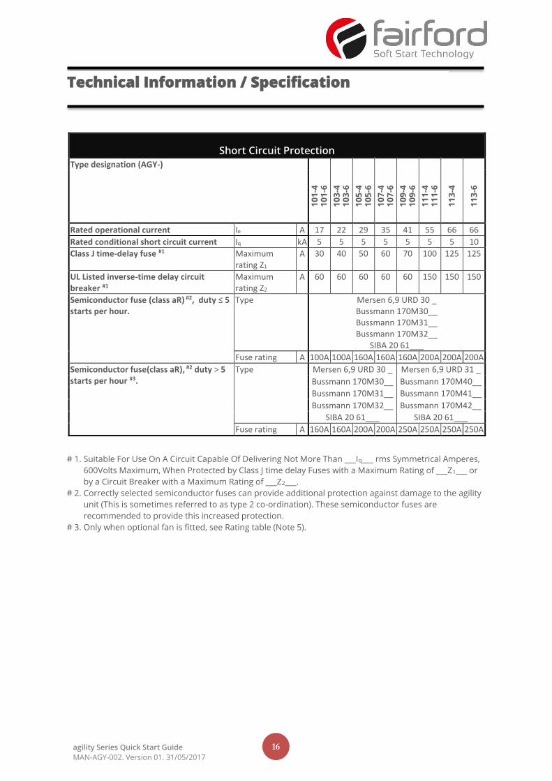
Short Circuit Protection
Type designation (AGY-)
10
1-4
1
01
-6
10
3-4
10
3-6
10
5-4
1
05
-6
10
7-4
10
7-6
10
9-4
10
9-6
11
1-4
1
11
-6
11
3-4
11
3-6
Rated operational current Ie A 17 22 29 35 41 55 66 66
Rated conditional short circuit current Iq kA 5 5 5 5 5 5 5 10
Class J time-delay fuse #1 Maximum rating Z1
A 30 40 50 60 70 100 125 125
UL Listed inverse-time delay circuit breaker #1
Maximum rating Z2
A 60 60 60 60 60 150 150 150
Semiconductor fuse (class aR) #2, duty ≤ 5 starts per hour.
Type Mersen 6,9 URD 30 _ Bussmann 170M30__ Bussmann 170M31__ Bussmann 170M32__
SIBA 20 61___
Fuse rating A 100A 100A 160A 160A 160A 200A 200A 200A
Semiconductor fuse(class aR), #2 duty > 5 starts per hour #3.
Type Mersen 6,9 URD 30 _ Mersen 6,9 URD 31 _
Bussmann 170M30__ Bussmann 170M40__
Bussmann 170M31__ Bussmann 170M41__
Bussmann 170M32__ Bussmann 170M42__
SIBA 20 61___ SIBA 20 61___
Fuse rating A 160A 160A 200A 200A 250A 250A 250A 250A
# 1. Suitable For Use On A Circuit Capable Of Delivering Not More Than ___Iq___ rms Symmetrical Amperes,
600Volts Maximum, When Protected by Class J time delay Fuses with a Maximum Rating of ___Z1___ or
by a Circuit Breaker with a Maximum Rating of ___Z2___.
# 2. Correctly selected semiconductor fuses can provide additional protection against damage to the agility
unit (This is sometimes referred to as type 2 co-ordination). These semiconductor fuses are
recommended to provide this increased protection.
# 3. Only when optional fan is fitted, see Rating table (Note 5).
Technical Information / Specification
17 agility Series Quick Start Guide
MAN-AGY-002. Version 01. 31/05/2017
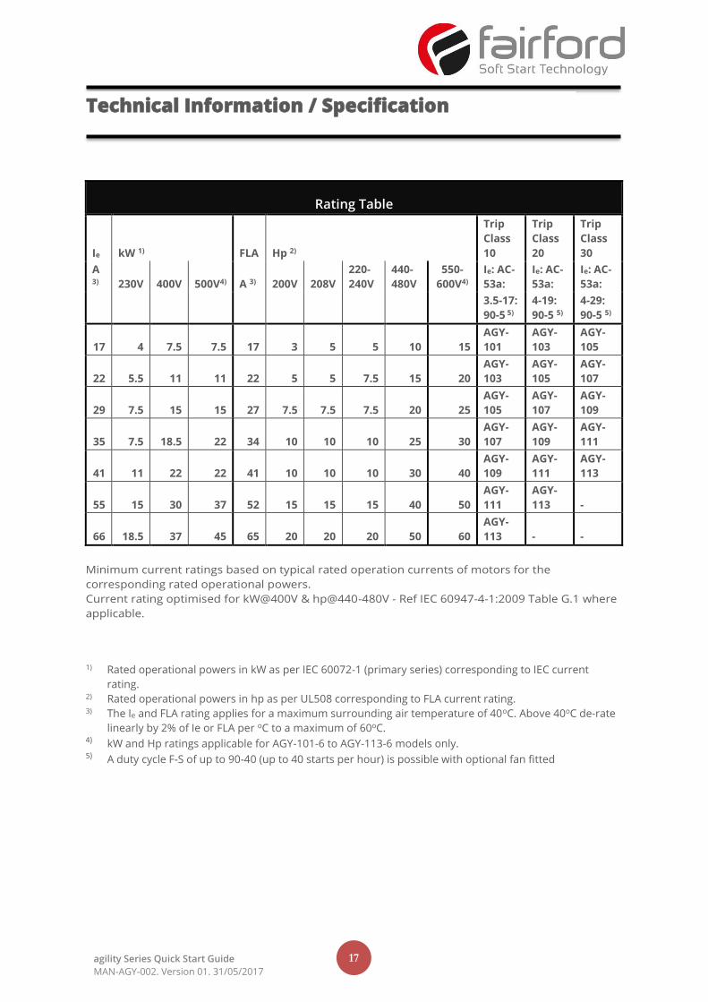
Rating Table
Ie kW 1)
FLA Hp 2)
Trip
Class
10
Trip
Class
20
Trip
Class
30
A 3) 230V 400V 500V4) A 3) 200V 208V
220-
240V
440-
480V
550-
600V4)
Ie: AC-
53a:
Ie: AC-
53a:
Ie: AC-
53a:
3.5-17:
90-5 5)
4-19:
90-5 5)
4-29:
90-5 5)
17 4 7.5 7.5 17 3 5 5 10 15
AGY-
101
AGY-
103
AGY-
105
22 5.5 11 11 22 5 5 7.5 15 20
AGY-
103
AGY-
105
AGY-
107
29 7.5 15 15 27 7.5 7.5 7.5 20 25
AGY-
105
AGY-
107
AGY-
109
35 7.5 18.5 22 34 10 10 10 25 30
AGY-
107
AGY-
109
AGY-
111
41 11 22 22 41 10 10 10 30 40
AGY-
109
AGY-
111
AGY-
113
55 15 30 37 52 15 15 15 40 50
AGY-
111
AGY-
113 -
66 18.5 37 45 65 20 20 20 50 60
AGY-
113 - -
Minimum current ratings based on typical rated operation currents of motors for the
corresponding rated operational powers.
Current rating optimised for kW@400V & hp@440-480V - Ref IEC 60947-4-1:2009 Table G.1 where
applicable.
1) Rated operational powers in kW as per IEC 60072-1 (primary series) corresponding to IEC current
rating. 2) Rated operational powers in hp as per UL508 corresponding to FLA current rating. 3) The Ie and FLA rating applies for a maximum surrounding air temperature of 40oC. Above 40oC de-rate
linearly by 2% of Ie or FLA per oC to a maximum of 60oC. 4) kW and Hp ratings applicable for AGY-101-6 to AGY-113-6 models only. 5) A duty cycle F-S of up to 90-40 (up to 40 starts per hour) is possible with optional fan fitted
Technical Information / Specification

18 agility Series Quick Start Guide
MAN-AGY-002. Version 01. 31/05/2017
Notes

19 agility Series Quick Start Guide
MAN-AGY-002. Version 01. 31/05/2017
Electric current, Danger to life!
Only skilled or instructed persons may carry out the operations.
Livsfara genom elektrisk ström!
Endast utbildade elektriker och personer som undervisats i elektroteknik får
utföra de arbeten som beskrivs nedan.
Lebensgefahr durch Strom!
Nur Elektrofachkräfte und elektrotechnisch unterwiesene Personen dürfen die
im Folgenden beschriebenen Arbeiten ausführen.
Hengenvaarallinen jännite!
Vain pätevät sähköasentajat ja opastusta saaneet henkilöt saavat suorittaa
seuraavat työt.
Tension électrique dangereuse!
Seules les personnes qualifiées et averties doivent exécuter les travaux ci-après.
Nebezpečí úrazu elektrickým proudem!
Níže uvedené práce smějí provádět pouze osoby s elektrotechnickým
vzděláním.
¡Corriente eléctrica! ¡Peligro de muerte!
El trabajo a continuación descrito debe ser realizado por personas cualificadas y
advertidas.
Eluohtlik! Elektrilöögioht!
Järgnevalt kirjeldatud töid tohib teostada ainult elektriala spetsialist vői
elektrotehnilise instrueerimise läbinud personal.
Tensione elettrica: Pericolo di morte!
Solo persone abilitate e qualificate possono eseguire le operazioni di seguito
riportate.
Életveszély az elektromos áram révén!
Csak elektromos szakemberek és elektrotechnikában képzett személyek
végezhetik el a következőkben leírt munkákat.
触电危险!
只允许专业人员和受过专业训练的人员进行下列工作。
Elektriskā strāva apdraud dzīvību!
Tālāk aprakstītos darbus drīkst veikt tikai elektrospeciālisti un darbam ar
elektrotehniskām iekārtām instruētās personas!
Электрический ток! Опасно для жизни!
Только специалисты или проинструктированные лица могут выполнять
следующие операции.
Pavojus gyvybei dėl elektros srovės!
Tik elektrikai ir elektrotechnikos specialistai gali atlikti žemiau aprašytus darbus.
Levensgevaar door elektrische stroom!
Uitsluitelijk deskundigen in elektriciteit en elektrotechnisch geinstrueerde
personen is het toegestaan, de navolgend beschrevene werkzaamheden uit te
voeren.
Porażenie prądem elektrycznym stanowi zagrożenie dla życia!
Opisane poniżej prace mogą przeprowadzać tylko wykwalifikowani elektrycy
oraz osoby odpowiednio poinstruowane w zakresie elektrotechniki.
Livsfare på grund af elektrisk strøm!
Kun uddannede el-installatører og personer der e instruerede i elektrotekniske
arbejdsopgaver, må udføre de nedenfor anførte arbejder.
Življenjska nevarnost zaradi električnega toka!
Spodaj opisana dela smejo izvajati samo elektrostrokovnjaki in elektrotehnično
poučene osebe.
Προσοχή, κίνδυνος ηλεκτροπληξίας!
Οι εργασίες που αναφέρονται στη συνέχεια θα πρέπει να εκτελούνται μόνο
από ηλεκτρολόγους και ηλεκτροτεχνίτες.
Nebezpečenstvo ohrozenia života elektrickým prúdom!
Práce, ktoré sú nižšie opísané, smú vykonávat’ iba elektroodborníci a osoby s
elektrotechnickým vzdelaním.
Perigo de vida devido a corrente eléctrica!
Apenas electricistas e pessoas com formação electrotécnica podem executar os
trabalhos que a seguir se descrevem.
Опасност за живота от електрически ток!
Операциите, описани в следващите раздели, могат да се извършват само
от специалисти-електротехници и инструктиран електротехнически
персонал.
Livsfara genom elektrisk ström!
Endast utbildade elektriker och personer som undervisats i elektroteknik får
utföra de arbeten som beskrivs nedan.
Atenţie! Pericol electric!
Toate lucrările descrise trebuie efectuate numai de personal de specialitate
calificat şi de persoane cu cunoştiinţe profunde în electrotehnică.
Hengenvaarallinen jännite!
Vain pätevät sähköasentajat ja opastusta saaneet henkilöt saavat suorittaa
seuraavat työt.
Življenjska nevarnost zaradi električnega toka!
Spodaj opisana dela smejo izvajati samo elektrostrokovnjaki in elektrotehnično
poučene osebe.
Nebezpečí úrazu elektrickým proudem!
Níže uvedené práce smějí provádět pouze osoby s elektrotechnickým
vzděláním.
Nebezpečenstvo ohrozenia života elektrickým prúdom!
Práce, ktoré sú nižšie opísané, smú vykonávat’ iba elektroodborníci a osoby s
elektrotechnickým vzdelaním.
Опасност за живота от електрически ток!
Операциите, описани в следващите раздели,
могат да се извършват само от
специалисти-електротехници и инструктиран
Eluohtlik! Elektrilöögioht!
Järgnevalt kirjeldatud töid tohib teostada ainult
elektriala spetsialist vői elektrotehnilise
instrueerimise läbinud personal.
Életveszély az elektromos áram révén!
Csak elektromos szakemberek és elektrotechnikában képzett személyek
végezhetik el a következőkben leírt munkákat.
Atenţie! Pericol electric!
Toate lucrările descrise trebuie efectuate numai de personal de specialitate
calificat şi de persoane cu cunoştiinţe profunde în electrotehnică.
Elektriskā strāva apdraud dzīvību!
Tālāk aprakstītos darbus drīkst veikt tikai elektrospeciālisti un darbam ar
elektrotehniskām iekārtām instruētās personas!
Pavojus gyvybei dėl elektros srovės!
Tik elektrikai ir elektrotechnikos specialistai gali atlikti žemiau aprašytus darbus.
Porażenie prądem elektrycznym stanowi zagrożenie dla życia!
Opisane poniżej prace mogą przeprowadzać tylko wykwalifikowani elektrycy
oraz osoby odpowiednio poinstruowane w zakresie elektrotechniki.