INFRARED WIRELESS TUNER IR-702T - TOA Electronicstoaelectronics.com/media/ir702t_mt1e.pdf · •...
28
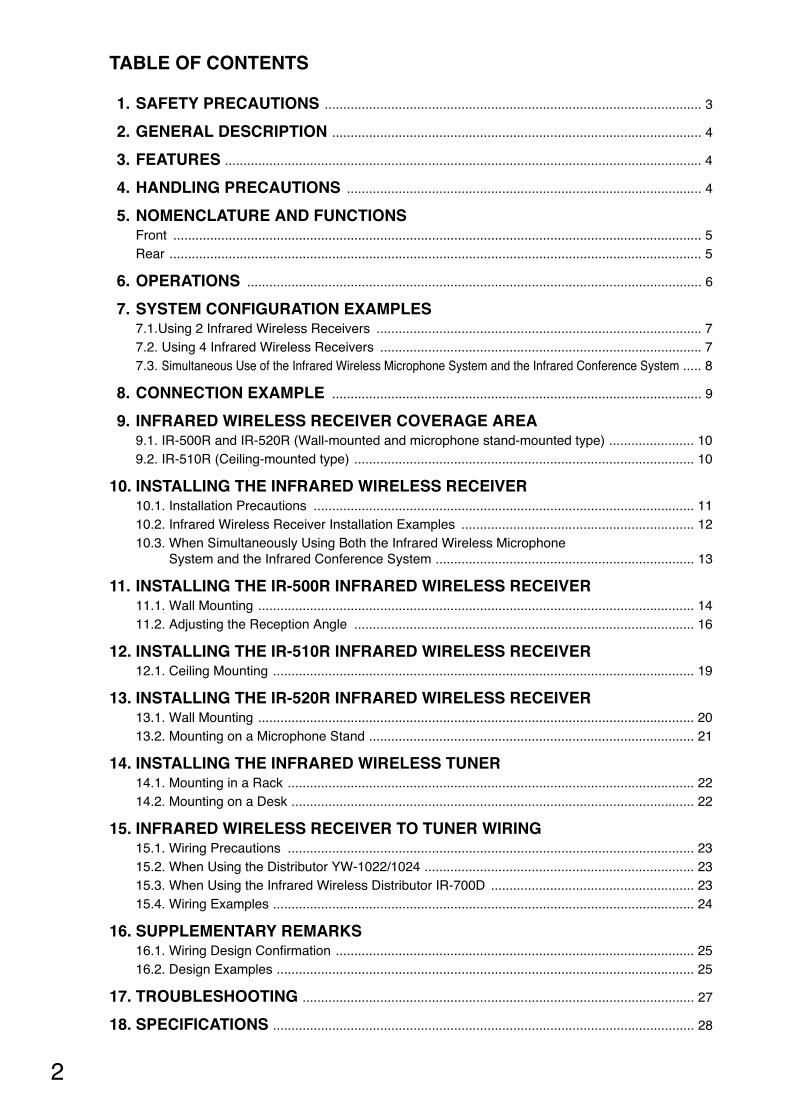
OPERATING INSTRUCTIONS INFRARED WIRELESS TUNER IR-702T CH A VOLUME IR CH B VOLUME POWER IR OFF ON Thank you for purchasing TOA's Infrared Wireless Tuner. Please carefully follow the instructions in this manual to ensure long, trouble-free use of your equipment. This manual describes the installation and usage of the entire system* using the IR-702T Infrared Wireless Tuner as well as the IR-702T. * The system described in this manual is comprised of the following components: • IR-702T Infrared Wireless Tuner • IR-200M and IR-300M Infrared Wireless Microphones • IR-500R, IR-510R, and IR-520R Infrared Wireless Receivers • IR-200BC Battery Charger • IR-200BT-2 Ni-MH Battery • YW-1022 and YW-1024 Distributors Note For the installation and usage of the IR-702T when used in combination with the IR-700D Infrared Wireless Distributor, refer to the installation manual enclosed with the IR-700D.
Transcript of INFRARED WIRELESS TUNER IR-702T - TOA Electronicstoaelectronics.com/media/ir702t_mt1e.pdf · •...
OPERATING INSTRUCTIONS
INFRARED WIRELESS TUNER IR-702T
CH AVOLUME
IR
CH BVOLUME
POWER
IR
OFF
ON
Thank you for purchasing TOA's Infrared Wireless Tuner. Please carefully follow the instructions in this manual to ensure long, trouble-free use of your equipment.
This manual describes the installation and usage of the entire system* using the IR-702T InfraredWireless Tuner as well as the IR-702T.
* The system described in this manual is comprised of the following components:
• IR-702T Infrared Wireless Tuner • IR-200M and IR-300M Infrared Wireless Microphones • IR-500R, IR-510R, and IR-520R Infrared Wireless Receivers • IR-200BC Battery Charger • IR-200BT-2 Ni-MH Battery • YW-1022 and YW-1024 Distributors
NoteFor the installation and usage of the IR-702T when used in combination with the IR-700DInfrared Wireless Distributor, refer to the installation manual enclosed with the IR-700D.
2
TABLE OF CONTENTS
1. SAFETY PRECAUTIONS ...................................................................................................... 3
2. GENERAL DESCRIPTION .................................................................................................... 4
3. FEATURES ................................................................................................................................. 4
4. HANDLING PRECAUTIONS ................................................................................................ 4
5. NOMENCLATURE AND FUNCTIONSFront ............................................................................................................................................... 5Rear ................................................................................................................................................ 5
6. OPERATIONS ........................................................................................................................... 6
7. SYSTEM CONFIGURATION EXAMPLES7.1.Using 2 Infrared Wireless Receivers ........................................................................................ 77.2. Using 4 Infrared Wireless Receivers ....................................................................................... 77.3. Simultaneous Use of the Infrared Wireless Microphone System and the Infrared Conference System ..... 8
8. CONNECTION EXAMPLE .................................................................................................... 9
9. INFRARED WIRELESS RECEIVER COVERAGE AREA9.1. IR-500R and IR-520R (Wall-mounted and microphone stand-mounted type) ....................... 109.2. IR-510R (Ceiling-mounted type) ............................................................................................ 10
10. INSTALLING THE INFRARED WIRELESS RECEIVER10.1. Installation Precautions ....................................................................................................... 1110.2. Infrared Wireless Receiver Installation Examples ............................................................... 1210.3. When Simultaneously Using Both the Infrared Wireless Microphone
System and the Infrared Conference System ...................................................................... 13
11. INSTALLING THE IR-500R INFRARED WIRELESS RECEIVER11.1. Wall Mounting ...................................................................................................................... 1411.2. Adjusting the Reception Angle ............................................................................................ 16
12. INSTALLING THE IR-510R INFRARED WIRELESS RECEIVER12.1. Ceiling Mounting .................................................................................................................. 19
13. INSTALLING THE IR-520R INFRARED WIRELESS RECEIVER13.1. Wall Mounting ...................................................................................................................... 2013.2. Mounting on a Microphone Stand ........................................................................................ 21
14. INSTALLING THE INFRARED WIRELESS TUNER14.1. Mounting in a Rack .............................................................................................................. 2214.2. Mounting on a Desk ............................................................................................................. 22
15. INFRARED WIRELESS RECEIVER TO TUNER WIRING15.1. Wiring Precautions .............................................................................................................. 2315.2. When Using the Distributor YW-1022/1024 ......................................................................... 2315.3. When Using the Infrared Wireless Distributor IR-700D ....................................................... 2315.4. Wiring Examples .................................................................................................................. 24
16. SUPPLEMENTARY REMARKS16.1. Wiring Design Confirmation ................................................................................................. 2516.2. Design Examples ................................................................................................................. 25
17. TROUBLESHOOTING .......................................................................................................... 27
18. SPECIFICATIONS .................................................................................................................. 28
3
When Installing the Unit
• Do not expose the unit to rain or an environmentwhere it may be splashed by water or other liquids,as doing so may result in fire or electric shock.
• Use the unit only with the voltage specified on theunit. Using a voltage higher than that which isspecified may result in fire or electric shock.
• Do not cut, kink, otherwise damage nor modify thepower supply cord. In addition, avoid using thepower cord in close proximity to heaters, and neverplace heavy objects -- including the unit itself -- onthe power cord, as doing so may result in fire orelectric shock.
When the Unit is in Use
• Should the following irregularity be found duringuse, immediately switch off the power, disconnectthe power supply plug from the AC outlet andcontact your nearest TOA dealer. Make no furtherattempt to operate the unit in this condition as thismay cause fire or electric shock. · If you detect smoke or a strange smell coming
from the unit.· If water or any metallic object gets into the unit · If the unit falls, or the unit case breaks · If the power supply cord is damaged (exposure of
the core, disconnection, etc.)· If it is malfunctioning (no tone sounds.)
• To prevent a fire or electric shock, never open norremove the unit case as there are high voltagecomponents inside the unit. Refer all servicing toqualified service personnel.
• Do not place cups, bowls, or other containers ofliquid or metallic objects on top of the unit. If theyaccidentally spill into the unit, this may cause a fireor electric shock.
• Do not touch a power supply plug during thunderand lightning, as this may result in electric shock.
When Installing the Unit
• Never plug in nor remove the power supply plugwith wet hands, as doing so may cause electricshock.
• When unplugging the power supply cord, be sureto grasp the power supply plug; never pull on thecord itself. Operating the unit with a damagedpower supply cord may cause a fire or electricshock.
• When moving the unit, be sure to remove its powersupply cord from the wall outlet. Moving the unitwith the power cord connected to the outlet maycause damage to the power cord, resulting in fire orelectric shock. When removing the power cord, besure to hold its plug to pull.
• Avoid installing the unit in humid or dusty locations,in locations exposed to the direct sunlight, near theheaters, or in locations generating sooty smoke orsteam as doing otherwise may result in fire orelectric shock.
• Refer all installation work to the dealer from wherethe unit was purchased. Installation requiresextensive technical knowledge and experience.Improper installation may result in personal injuryor electric shock.
1. SAFETY PRECAUTIONS
These precautions apply only to the IR-702T Infrared Wireless Tuner. For precautions regarding other infrared microphone system devices, please refer to theinstruction manual included with each device.
• Before installation or use, be sure to carefully read all the instructions in this section for correct and safeoperation.
• Be sure to follow all the precautionary instructions in this section, which contain important warnings and/orcautions regarding safety.
• After reading, keep this manual handy for future reference.
WARNING
Indicates a potentially hazardous situation which, if mishandled, couldresult in death or serious personal injury.
Indicates a potentially hazardous situation which, if mishandled, couldresult in moderate or minor personal injury, and/or property damage.
WARNING
CAUTION
CAUTION
4
When the Unit is in Use
• Use the AC adapter supplied with the unit. Notethat the use of other adapter may cause a fire.
• If dust accumulates on the power supply plug or inthe wall AC outlet, a fire may result. Clean itperiodically. In addition, insert the plug in the walloutlet securely.
• Switch off the power, and unplug the power supplyplug from the AC outlet for safety purposes whencleaning or leaving the unit unused for 10 days ormore. Doing otherwise may cause a fire or electricshock.
2. GENERAL DESCRIPTION
The IR-702T is a 2-channel infrared wireless tuner employing a fixed frequency system. This tuner is combined with an infrared wireless microphone and an infrared wireless receiver to make up theinfrared wireless microphone system. The infrared microphone system eliminates problems with interference or eavesdropping, allowingsimultaneous use in adjacent conference rooms or school classrooms.
3. FEATURES
• The YW-1022 or YW-1024 Distributor allows up to 4 infrared wireless receivers to be installed.
• Up to 16 infrared wireless receivers can be installed with the use of the IR-700D Infrared WirelessDistributor.
• Since the IR-702T tuner uses a frequency band that does not interfere with that of the infrared conferencesystem (TS-800 and TS-900 Series), both the infrared wireless microphone system and the conferencesystem can be simultaneously installed in the same location.
4. HANDLING PRECAUTIONS
• The supplied power supply cord is designed for exclusive use with the IR-702T. Never use it with otherequipment.
• Install the IR-702T as far as possible from fluorescent lights, digital equipment, PCs and other devices thatgenerate high-frequency noise.
• The IR-702T is an infrared wireless system which prevents transmitted contents from being revealed topeople outside walls or other shields. However, since transmissions may be eavesdropped by maliciousthird parties, it is strongly suggested that the user take responsibility for carrying out measures to preventeavesdropping. TOA assumes no responsibility for any damages that may be sustained without takingappropriate protective measures against eavesdropping.
• When cleaning, be sure to first switch off the tuner's power, then wipe with a dry cloth. If the tuner isextremely dirty, use a cloth moistened in a neutral detergent. Do not use benzene, thinner, alcohol andchemically-processed towels, as they can cause damage to the tuner's components and parts.
This device complies with Part 15 of the FCC Rules. Operation is subject to the following two conditions: (1) this device may not cause harmful interference, and (2) this device must accept any interference received, including interference that may cause undesiredoperation.Any modifications made to this device that are not approved by TOA Corporation may void the authoritygranted the user by the FCC to operate this equipment.
FCC Compliance
5
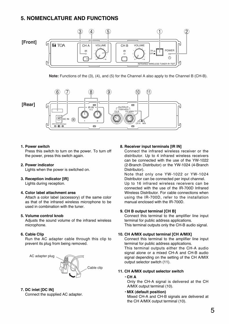
1. Power switchPress this switch to turn on the power. To turn offthe power, press this switch again.
2. Power indicatorLights when the power is switched on.
3. Reception indicator [IR]Lights during reception.
4. Color label attachment areaAttach a color label (accessory) of the same coloras that of the infrared wireless microphone to beused in combination with the tuner.
5. Volume control knobAdjusts the sound volume of the infrared wirelessmicrophone.
6. Cable ClipRun the AC adapter cable through this clip toprevent its plug from being removed.
7. DC inlet [DC IN]Connect the supplied AC adapter.
8. Receiver input terminals [IR IN]Connect the infrared wireless receiver or thedistributor. Up to 4 infrared wireless receiverscan be connected with the use of the YW-1022(2-Branch Distributor) or the YW-1024 (4-BranchDistributor). Note that only one YW-1022 or YW-1024Distributor can be connected per input channel.Up to 16 infrared wireless receivers can beconnected with the use of the IR-700D InfraredWireless Distributor. For cable connections whenusing the IR-700D, refer to the installationmanual enclosed with the IR-700D.
9. CH B output terminal [CH B]Connect this terminal to the amplifier line inputterminal for public address applications. This terminal outputs only the CH-B audio signal.
10. CH A/MIX output terminal [CH A/MIX]Connect this terminal to the amplifier line inputterminal for public address applications. This terminal outputs either the CH-A audiosignal alone or a mixed CH-A and CH-B audiosignal depending on the setting of the CH A/MIXoutput selector switch (11).
11. CH A/MIX output selector switch• CH A
Only the CH-A signal is delivered at the CHA/MIX output terminal (10).
• MIX (default position)Mixed CH-A and CH-B signals are delivered atthe CH A/MIX output terminal (10).
5. NOMENCLATURE AND FUNCTIONS
CH A VOLUME
IR
CH B VOLUME
POWERIROFF
ON
IR IN OUTPUT–10dBV/600Ω75 Ω
1 2
CH B
CH A
DC IN
24V 0.6A(max) MIX
CH A/MIX
1 23 4 5
Note: Functions of the (3), (4), and (5) for the Channel A also apply to the Channel B (CH-B).
6 7 8 9 10 11
[Front]
[Rear]
Cable clip
AC adapter plug
6
6. OPERATIONS
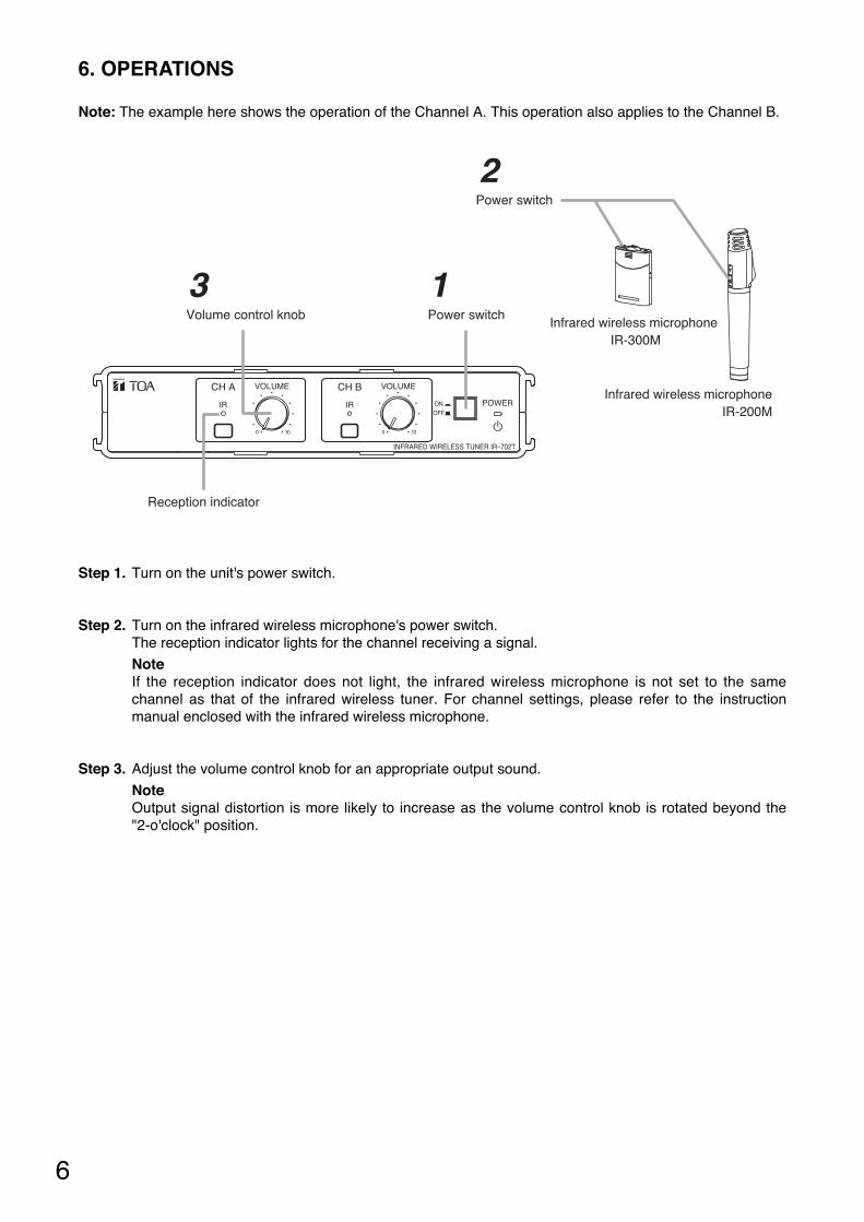
Note: The example here shows the operation of the Channel A. This operation also applies to the Channel B.
CH A VOLUME
IR
CH B VOLUME
POWERIROFF
ON
2
1Power switch
Power switch
Infrared wireless microphoneIR-200M
Infrared wireless microphone IR-300M
3Volume control knob
Reception indicator
Step 1. Turn on the unit's power switch.
Step 2. Turn on the infrared wireless microphone's power switch.The reception indicator lights for the channel receiving a signal.
NoteIf the reception indicator does not light, the infrared wireless microphone is not set to the samechannel as that of the infrared wireless tuner. For channel settings, please refer to the instructionmanual enclosed with the infrared wireless microphone.
Step 3. Adjust the volume control knob for an appropriate output sound.
NoteOutput signal distortion is more likely to increase as the volume control knob is rotated beyond the"2-o'clock" position.
7
7. SYSTEM CONFIGURATION EXAMPLES
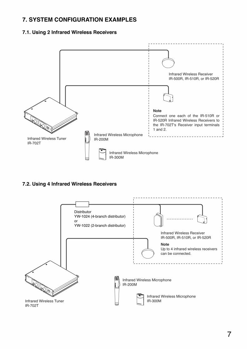
7.1. Using 2 Infrared Wireless Receivers
Infrared Wireless TunerIR-702T
Infrared Wireless ReceiverIR-500R, IR-510R, or IR-520R
Infrared Wireless MicrophoneIR-200M
Infrared Wireless MicrophoneIR-300M
NoteConnect one each of the IR-510R or IR-520R Infrared Wireless Receivers to the IR-702T's Receiver input terminals 1 and 2.
7.2. Using 4 Infrared Wireless Receivers
Infrared Wireless TunerIR-702T
DistributorYW-1024 (4-branch distributor) or YW-1022 (2-branch distributor)
Infrared Wireless ReceiverIR-500R, IR-510R, or IR-520R
NoteUp to 4 infrared wireless receivers can be connected.
Infrared Wireless MicrophoneIR-200M
Infrared Wireless MicrophoneIR-300M
8
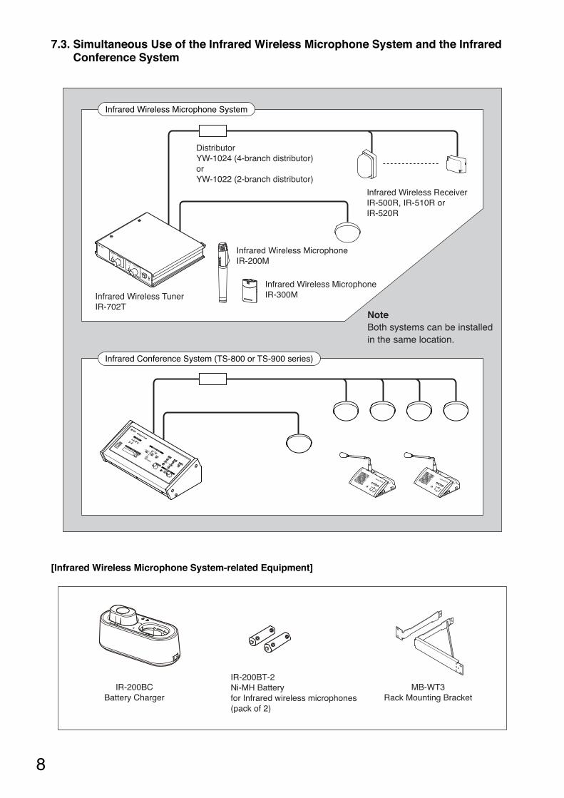
7.3. Simultaneous Use of the Infrared Wireless Microphone System and the InfraredConference System
Infrared Wireless TunerIR-702T
DistributorYW-1024 (4-branch distributor) or YW-1022 (2-branch distributor)
Infrared Wireless ReceiverIR-500R, IR-510R or IR-520R
Infrared Wireless MicrophoneIR-200M
Infrared Wireless MicrophoneIR-300M
Infrared Wireless Microphone System
Infrared Conference System (TS-800 or TS-900 series)
NoteBoth systems can be installed in the same location.
[Infrared Wireless Microphone System-related Equipment]
IR-200BCBattery Charger
MB-WT3Rack Mounting Bracket
IR-200BT-2 Ni-MH Battery for Infrared wireless microphones (pack of 2)
9
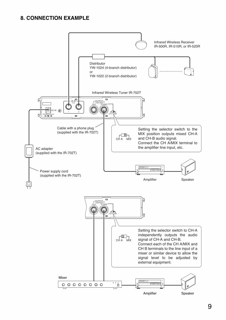
8. CONNECTION EXAMPLE
IR IN OUTPUT–10dBV/600Ω75 Ω
1 2
CH B
CH A
DC IN
24V 0.6A(max) MIX
CH A/MIX
OUTPUT–10dBV/600Ω
CH B
CH A MIX
CH A/MIX
DistributorYW-1024 (4-branch distributor) or YW-1022 (2-branch distributor)
Infrared Wireless ReceiverIR-500R, IR-510R, or IR-520R
AC adapter (supplied with the IR-702T)
Power supply cord (supplied with the IR-702T)
Infrared Wireless Tuner IR-702T
Cable with a phone plug (supplied with the IR-702T)
SpeakerAmplifier
SpeakerAmplifier
Mixer
Setting the selector switch to the MIX position outputs mixed CH-A and CH-B audio signal.Connect the CH A/MIX terminal to the amplifier line input, etc.
Setting the selector switch to CH-A independently outputs the audio signal of CH-A and CH-B.Connect each of the CH A/MIX and CH B terminals to the line input of a mixer or similar device to allow the signal level to be adjusted by external equipment.
10
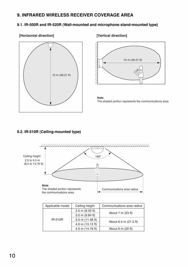
9.2. IR-510R (Ceiling-mounted type)
9. INFRARED WIRELESS RECEIVER COVERAGE AREA
150ºCeiling height 2.5 to 4.5 m (8.2 to 14.76 ft)
Communications area radiusNoteThe shaded portion represents the communications area.
Applicable model
IR-510R
2.5 m (8.20 ft)3.0 m (9.84 ft)3.5 m (11.48 ft)4.0 m (13.12 ft)4.5 m (14.76 ft)
About 7 m (23 ft)
About 6.5 m (21.5 ft)
About 6 m (20 ft)
Ceiling height Communications area radius
9.1. IR-500R and IR-520R (Wall-mounted and microphone stand-mounted type)
15 m (49.21 ft)
[Horizontal direction] [Vertical direction]
NoteThe shaded portion represents the communications area.
15 m (49.21 ft)
11
10.1. Installation Precautions
Because the infrared wireless microphone and receiver have their own directivity for infrared transmission andreception, take care that they are installed and operated under stable communication conditions.
• Number of infrared wireless receiversUse 2 or more receives.
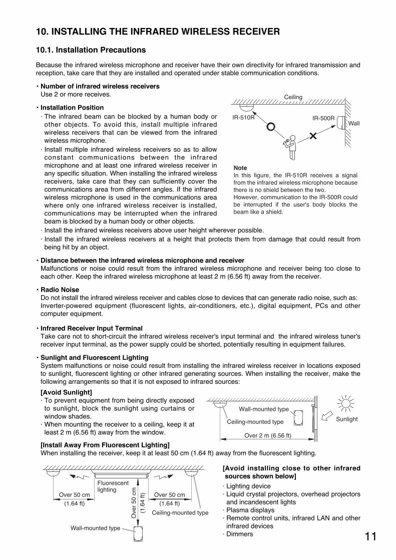
• Installation Position· The infrared beam can be blocked by a human body or
other objects. To avoid this, install multiple infraredwireless receivers that can be viewed from the infraredwireless microphone.
· Install multiple infrared wireless receivers so as to allowconstant communications between the infraredmicrophone and at least one infrared wireless receiver inany specific situation. When installing the infrared wirelessreceivers, take care that they can sufficiently cover thecommunications area from different angles. If the infraredwireless microphone is used in the communications areawhere only one infrared wireless receiver is installed,communications may be interrupted when the infraredbeam is blocked by a human body or other objects.
· Install the infrared wireless receivers above user height wherever possible. · Install the infrared wireless receivers at a height that protects them from damage that could result from
being hit by an object.
• Distance between the infrared wireless microphone and receiverMalfunctions or noise could result from the infrared wireless microphone and receiver being too close toeach other. Keep the infrared wireless microphone at least 2 m (6.56 ft) away from the receiver.
• Radio NoiseDo not install the infrared wireless receiver and cables close to devices that can generate radio noise, such as: Inverter-powered equipment (fluorescent lights, air-conditioners, etc.), digital equipment, PCs and othercomputer equipment.
• Infrared Receiver Input TerminalTake care not to short-circuit the infrared wireless receiver's input terminal and the infrared wireless tuner'sreceiver input terminal, as the power supply could be shorted, potentially resulting in equipment failures.
• Sunlight and Fluorescent LightingSystem malfunctions or noise could result from installing the infrared wireless receiver in locations exposedto sunlight, fluorescent lighting or other infrared generating sources. When installing the receiver, make thefollowing arrangements so that it is not exposed to infrared sources:
[Avoid Sunlight]· To prevent equipment from being directly exposed
to sunlight, block the sunlight using curtains orwindow shades.
· When mounting the receiver to a ceiling, keep it atleast 2 m (6.56 ft) away from the window.
[Install Away From Fluorescent Lighting]When installing the receiver, keep it at least 50 cm (1.64 ft) away from the fluorescent lighting.
10. INSTALLING THE INFRARED WIRELESS RECEIVER
IR-510R IR-500R
Ceiling
Wall
NoteIn this figure, the IR-510R receives a signal from the infrared wireless microphone because there is no shield between the two.However, communication to the IR-500R could be interrupted if the user's body blocks the beam like a shield.
Over 2 m (6.56 ft)
SunlightCeiling-mounted type
Wall-mounted type
Fluorescentlighting
Ove
r 50
cm
(1.6
4 ft)
Ceiling-mounted type
Wall-mounted type
Over 50 cm(1.64 ft)
Over 50 cm(1.64 ft)
[Avoid installing close to other infraredsources shown below]
· Lighting device· Liquid crystal projectors, overhead projectorsand incandescent lights
· Plasma displays· Remote control units, infrared LAN and otherinfrared devices
· Dimmers
12
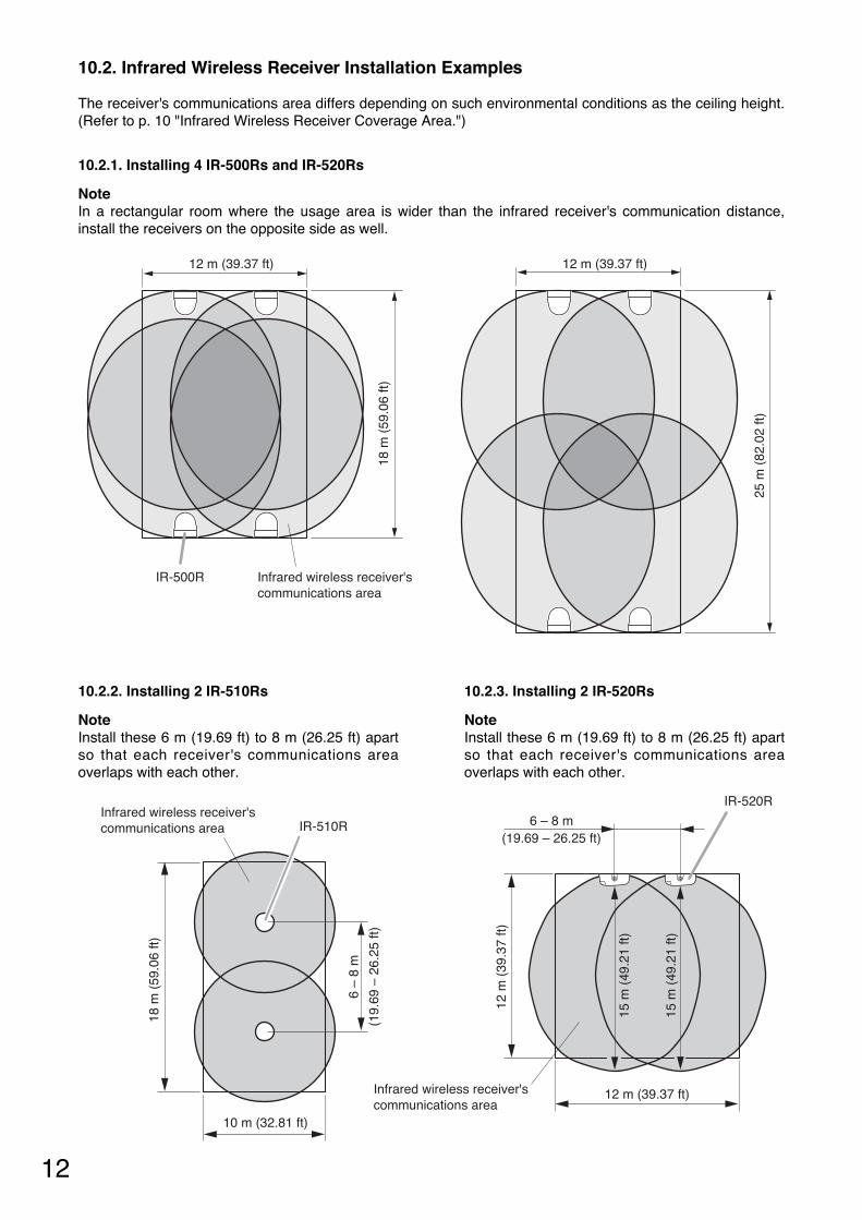
10.2. Infrared Wireless Receiver Installation Examples
The receiver's communications area differs depending on such environmental conditions as the ceiling height.(Refer to p. 10 "Infrared Wireless Receiver Coverage Area.")
10.2.2. Installing 2 IR-510Rs
NoteInstall these 6 m (19.69 ft) to 8 m (26.25 ft) apartso that each receiver's communications areaoverlaps with each other.
10.2.3. Installing 2 IR-520Rs
NoteInstall these 6 m (19.69 ft) to 8 m (26.25 ft) apartso that each receiver's communications areaoverlaps with each other.
6 –
8 m
(19.
69 –
26.
25 ft
)
Infrared wireless receiver's communications area IR-510R
18 m
(59
.06
ft)
10 m (32.81 ft)
15 m
(49
.21
ft)
15 m
(49
.21
ft)
12 m
(39
.37
ft)
12 m (39.37 ft)
IR-520R
6 – 8 m(19.69 – 26.25 ft)
Infrared wireless receiver's communications area
10.2.1. Installing 4 IR-500Rs and IR-520Rs
NoteIn a rectangular room where the usage area is wider than the infrared receiver's communication distance,install the receivers on the opposite side as well.
12 m (39.37 ft) 12 m (39.37 ft)
25 m
(82
.02
ft)
18 m
(59
.06
ft)
IR-500R Infrared wireless receiver's communications area
13
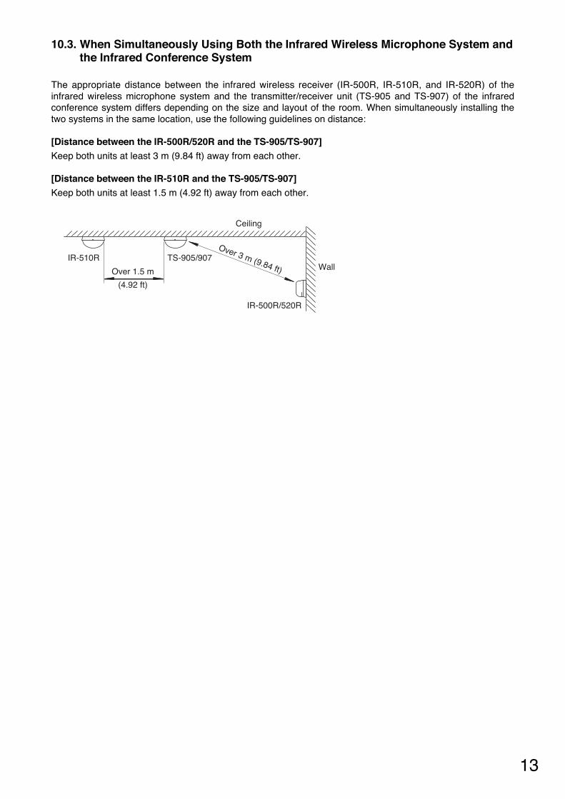
10.3. When Simultaneously Using Both the Infrared Wireless Microphone System andthe Infrared Conference System
The appropriate distance between the infrared wireless receiver (IR-500R, IR-510R, and IR-520R) of theinfrared wireless microphone system and the transmitter/receiver unit (TS-905 and TS-907) of the infraredconference system differs depending on the size and layout of the room. When simultaneously installing thetwo systems in the same location, use the following guidelines on distance:
[Distance between the IR-500R/520R and the TS-905/TS-907]Keep both units at least 3 m (9.84 ft) away from each other.
[Distance between the IR-510R and the TS-905/TS-907]Keep both units at least 1.5 m (4.92 ft) away from each other.
Over 1.5 m
(4.92 ft)
Over 3 m (9.84 ft)TS-905/907
Ceiling
WallIR-510R
IR-500R/520R
14
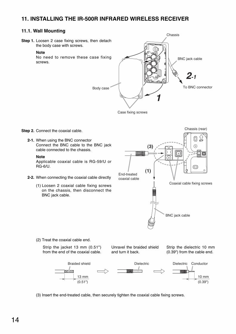
11.1. Wall Mounting
11. INSTALLING THE IR-500R INFRARED WIRELESS RECEIVER
Chassis
BNC jack cable
To BNC connector
1
2-1
Case fixing screws
Body case
Step 1. Loosen 2 case fixing screws, then detachthe body case with screws.
NoteNo need to remove these case fixingscrews.
Step 2. Connect the coaxial cable.
2-1. When using the BNC connectorConnect the BNC cable to the BNC jackcable connected to the chassis.
NoteApplicable coaxial cable is RG-59/U orRG-6/U.
2-2. When connecting the coaxial cable directly
(1) Loosen 2 coaxial cable fixing screwson the chassis, then disconnect theBNC jack cable.
Strip the jacket 13 mm (0.51")from the end of the coaxial cable.
Strip the dielectric 10 mm(0.39") from the cable end.
Unravel the braided shieldand turn it back.
Braided shield Dielectric
10 mm(0.39")
13 mm(0.51")
Dielectric Conductor
(2) Treat the coaxial cable end.
(3) Insert the end-treated cable, then securely tighten the coaxial cable fixing screws.
Chassis (rear)
Coaxial cable fixing screws
End-treated coaxial cable
BNC jack cable
(1)
(3)
15
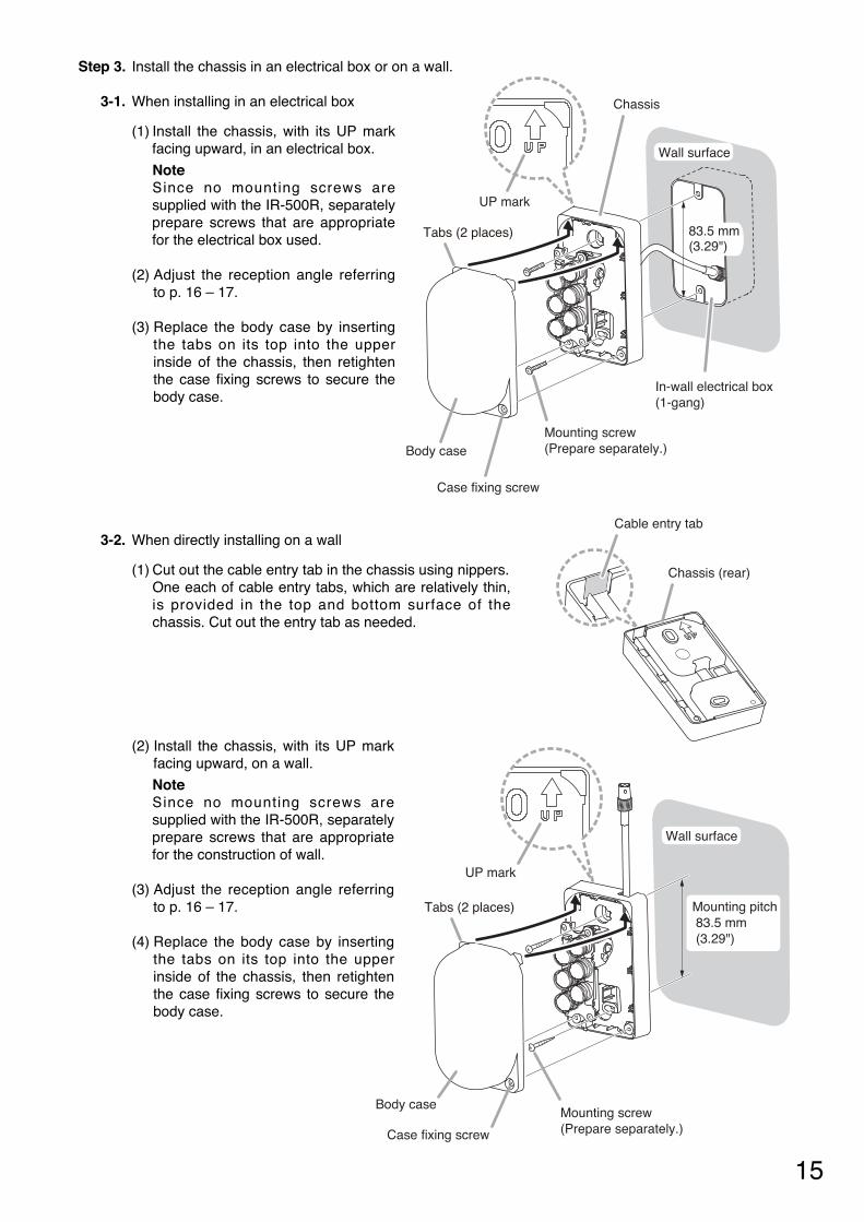
Step 3. Install the chassis in an electrical box or on a wall.
3-1. When installing in an electrical box
(1) Install the chassis, with its UP markfacing upward, in an electrical box.
NoteSince no mounting screws aresupplied with the IR-500R, separatelyprepare screws that are appropriatefor the electrical box used.
(2) Adjust the reception angle referringto p. 16 – 17.
(3) Replace the body case by insertingthe tabs on its top into the upperinside of the chassis, then retightenthe case fixing screws to secure thebody case.
3-2. When directly installing on a wall
(1) Cut out the cable entry tab in the chassis using nippers.One each of cable entry tabs, which are relatively thin,is provided in the top and bottom surface of thechassis. Cut out the entry tab as needed.
In-wall electrical box(1-gang)
Chassis
UP mark
Case fixing screw
Body case
Wall surface
83.5 mm(3.29")
Tabs (2 places)
Mounting screw (Prepare separately.)
Cable entry tab
Chassis (rear)
Mounting screw (Prepare separately.)Case fixing screw
Body case
UP mark
Tabs (2 places)
Wall surface
Mounting pitch 83.5 mm (3.29")
(2) Install the chassis, with its UP markfacing upward, on a wall.
NoteSince no mounting screws aresupplied with the IR-500R, separatelyprepare screws that are appropriatefor the construction of wall.
(3) Adjust the reception angle referringto p. 16 – 17.
(4) Replace the body case by insertingthe tabs on its top into the upperinside of the chassis, then retightenthe case fixing screws to secure thebody case.
16
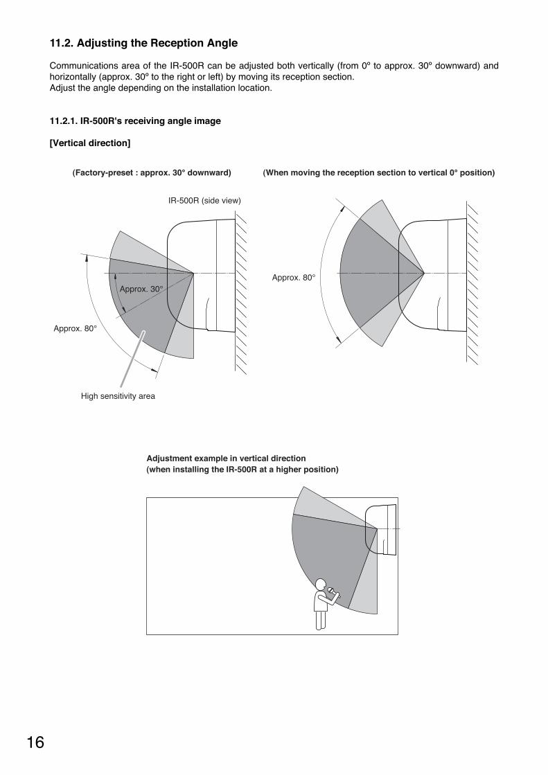
(Factory-preset : approx. 30° downward) (When moving the reception section to vertical 0° position)
IR-500R (side view)
Adjustment example in vertical direction(when installing the IR-500R at a higher position)
High sensitivity area
Approx. 30°
Approx. 80°
Approx. 80°
11.2. Adjusting the Reception Angle
Communications area of the IR-500R can be adjusted both vertically (from 0º to approx. 30º downward) andhorizontally (approx. 30º to the right or left) by moving its reception section.Adjust the angle depending on the installation location.
11.2.1. IR-500R's receiving angle image
[Vertical direction]
17
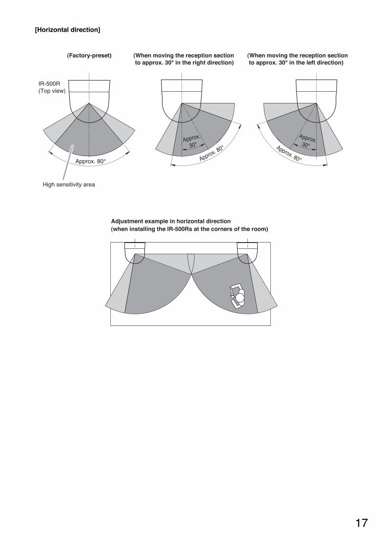
[Horizontal direction]
(Factory-preset) (When moving the reception section to approx. 30° in the right direction)
(When moving the reception section to approx. 30° in the left direction)
High sensitivity area
IR-500R(Top view)
Adjustment example in horizontal direction(when installing the IR-500Rs at the corners of the room)
Approx. 80° Approx. 80° Approx. 80°
Approx.
30°
Approx.30°
18
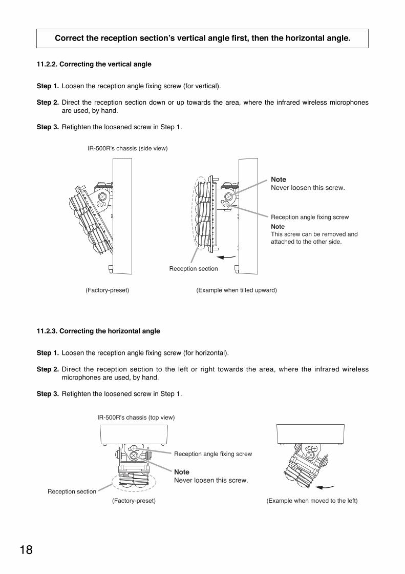
11.2.3. Correcting the horizontal angle
Step 1. Loosen the reception angle fixing screw (for horizontal).
Step 2. Direct the reception section to the left or right towards the area, where the infrared wirelessmicrophones are used, by hand.
Step 3. Retighten the loosened screw in Step 1.
Reception angle fixing screw
Reception section
IR-500R's chassis (top view)
(Factory-preset) (Example when moved to the left)
NoteNever loosen this screw.
11.2.2. Correcting the vertical angle
Step 1. Loosen the reception angle fixing screw (for vertical).
Step 2. Direct the reception section down or up towards the area, where the infrared wireless microphonesare used, by hand.
Step 3. Retighten the loosened screw in Step 1.
Reception angle fixing screw
NoteThis screw can be removed and attached to the other side.
(Factory-preset)
Reception section
NoteNever loosen this screw.
(Example when tilted upward)
IR-500R's chassis (side view)
Correct the reception section’s vertical angle first, then the horizontal angle.
19
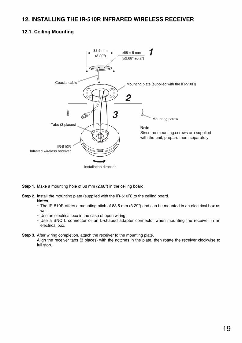
Step 1. Make a mounting hole of 68 mm (2.68") in the ceiling board.
Step 2. Install the mounting plate (supplied with the IR-510R) to the ceiling board.Notes• The IR-510R offers a mounting pitch of 83.5 mm (3.29") and can be mounted in an electrical box as
well. • Use an electrical box in the case of open wiring.• Use a BNC L connector or an L-shaped adapter connector when mounting the receiver in an
electrical box.
Step 3. After wiring completion, attach the receiver to the mounting plate. Align the receiver tabs (3 places) with the notches in the plate, then rotate the receiver clockwise tofull stop.
12.1. Ceiling Mounting
Installation direction
NoteSince no mounting screws are supplied with the unit, prepare them separately.
83.5 mm(3.29")
ø68 ± 5 mm
(ø2.68" ±0.2")
Mounting plate (supplied with the IR-510R)Coaxial cable
IR-510RInfrared wireless receiver
Tabs (3 places)
Mounting screw
1
2
3
12. INSTALLING THE IR-510R INFRARED WIRELESS RECEIVER
20
Coaxial cable
Chassis
Wall surface
Mounting screw (Prepare separately.)
Oval hole4.5 x 8 mm(0.18" x 0.31")
Body case
Case fixing screw
1, 3
2
4
NoteNo need to remove this case fixing screw.
62 mm (2.44")
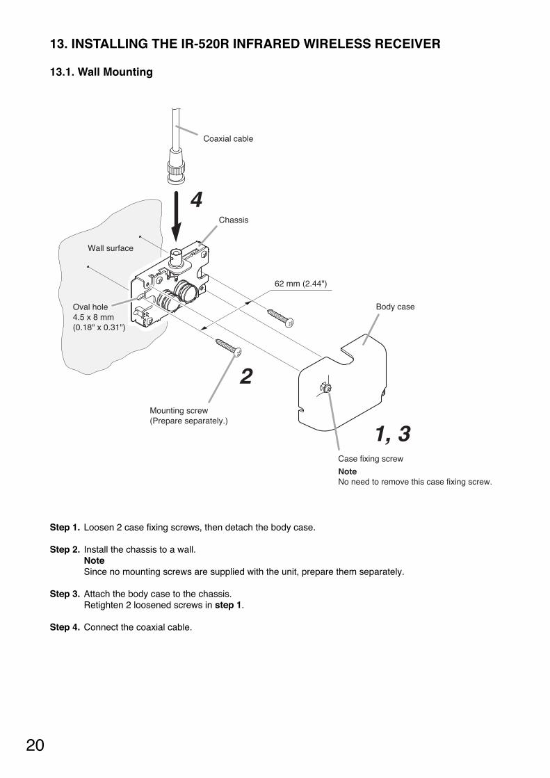
Step 1. Loosen 2 case fixing screws, then detach the body case.
Step 2. Install the chassis to a wall.NoteSince no mounting screws are supplied with the unit, prepare them separately.
Step 3. Attach the body case to the chassis.Retighten 2 loosened screws in step 1.
Step 4. Connect the coaxial cable.
13.1. Wall Mounting
13. INSTALLING THE IR-520R INFRARED WIRELESS RECEIVER
21
Coaxial cable
Chassis
Machine screw M4 x 10 (supplied with the IR-520R)
Microphone stand Mounting screw: U 5/16
Stand mounting bracket (supplied with the IR-520R)
Body case
3
2 , 4
1
5
Case fixing screw
NoteNo need to remove this case fixing screw.
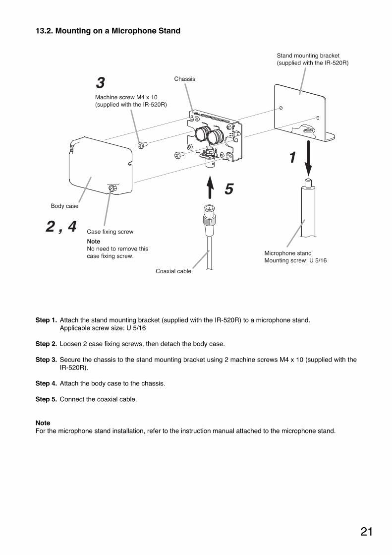
Step 1. Attach the stand mounting bracket (supplied with the IR-520R) to a microphone stand.Applicable screw size: U 5/16
Step 2. Loosen 2 case fixing screws, then detach the body case.
Step 3. Secure the chassis to the stand mounting bracket using 2 machine screws M4 x 10 (supplied with theIR-520R).
Step 4. Attach the body case to the chassis.
Step 5. Connect the coaxial cable.
NoteFor the microphone stand installation, refer to the instruction manual attached to the microphone stand.
13.2. Mounting on a Microphone Stand

22
Rack mounting screw 5 x 12*
* Component parts of the MB-WT3
Bracket B*
Bracket A*
Fiber washer (for M5)*
Infrared Wireless TunerIR-702T
Use the optional MB-WT3 Mounting Bracket when installing the unit in a rack.
NoteFor the mounting bracket installation, refer to the instruction manual attached to the MB-WT3.
14.1. Mounting in a Rack
When installing the unit on a desk, secure 4 supplied rubber feet to the unit's bottom.
14.2. Mounting on a Desk
14. INSTALLING THE INFRARED WIRELESS TUNER
Rubber foot (supplied with the IR-702T)
IR-702Tbottom surface
23
15. INFRARED WIRELESS RECEIVER TO TUNER WIRING
15.1. Wiring Precautions
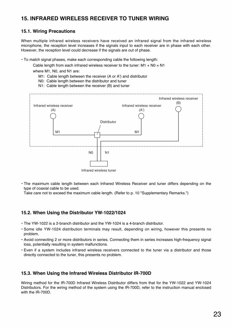
When multiple infrared wireless receivers have received an infrared signal from the infrared wirelessmicrophone, the reception level increases if the signals input to each receiver are in phase with each other.However, the reception level could decrease if the signals are out of phase.
• To match signal phases, make each corresponding cable the following length:
Cable length from each infrared wireless receiver to the tuner: M1 + N0 = N1
where M1, N0, and N1 are:M1: Cable length between the receiver (A or A') and distributorN0: Cable length between the distributor and tunerN1: Cable length between the receiver (B) and tuner
Infrared wireless receiver(B)
Infrared wireless receiver(A)
Infrared wireless receiver(A’)
Distributor
Infrared wireless tuner
M1 M1
N0 N1
15.2. When Using the Distributor YW-1022/1024
• The YW-1022 is a 2-branch distributor and the YW-1024 is a 4-branch distributor.
• Some idle YW-1024 distribution terminals may result, depending on wiring, however this presents noproblem.
• Avoid connecting 2 or more distributors in series. Connecting them in series increases high-frequency signalloss, potentially resulting in system malfunctions.
• Even if a system includes infrared wireless receivers connected to the tuner via a distributor and thosedirectly connected to the tuner, this presents no problem.
15.3. When Using the Infrared Wireless Distributor IR-700D
Wiring method for the IR-700D Infrared Wireless Distributor differs from that for the YW-1022 and YW-1024Distributors. For the wiring method of the system using the IR-700D, refer to the instruction manual enclosedwith the IR-700D.
• The maximum cable length between each Infrared Wireless Receiver and tuner differs depending on thetype of coaxial cable to be used. Take care not to exceed the maximum cable length. (Refer to p. 10 "Supplementary Remarks.")
24
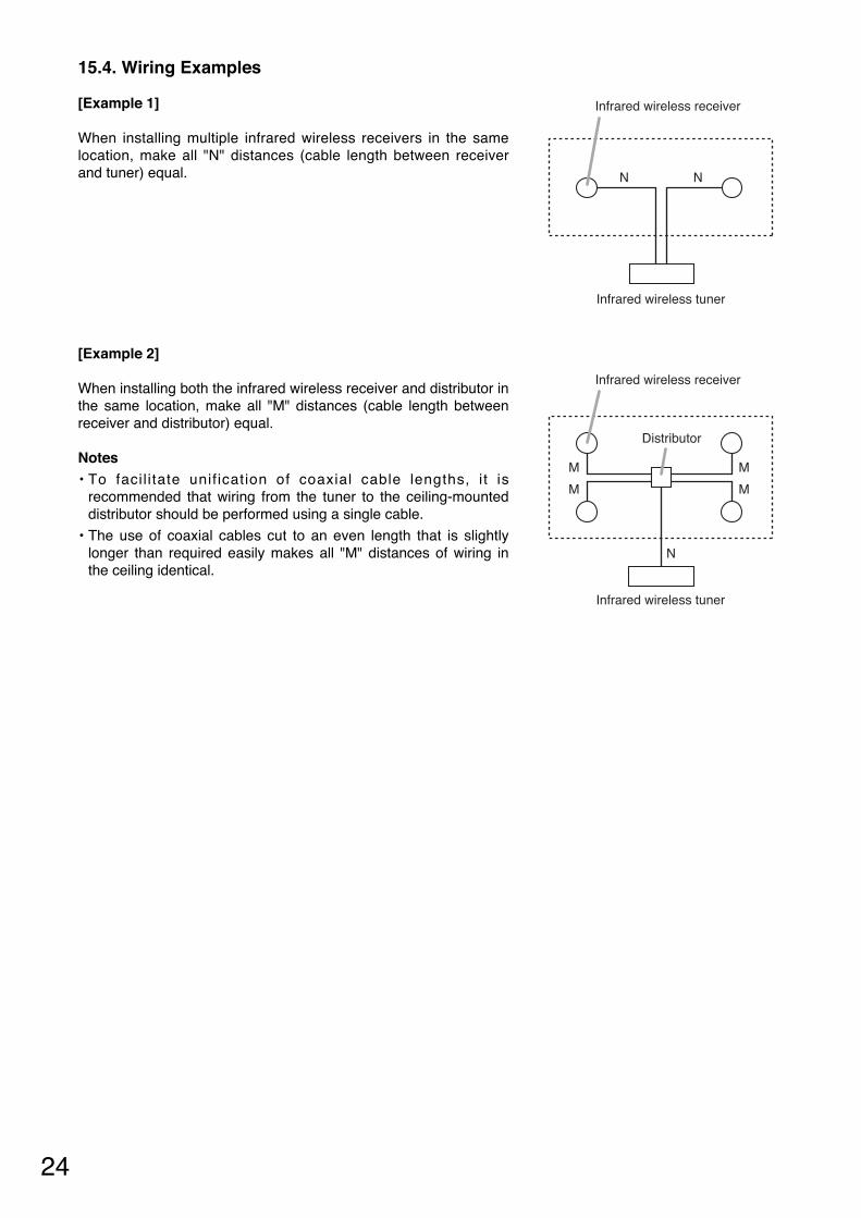
[Example 2]
When installing both the infrared wireless receiver and distributor inthe same location, make all "M" distances (cable length betweenreceiver and distributor) equal.
Notes• To facil i tate unif ication of coaxial cable lengths, i t is
recommended that wiring from the tuner to the ceiling-mounteddistributor should be performed using a single cable.
• The use of coaxial cables cut to an even length that is slightlylonger than required easily makes all "M" distances of wiring inthe ceiling identical.
Distributor
Infrared wireless receiver
Infrared wireless tuner
M
M
M
M
N
15.4. Wiring Examples
[Example 1]
When installing multiple infrared wireless receivers in the samelocation, make all "N" distances (cable length between receiverand tuner) equal. NN
Infrared wireless tuner
Infrared wireless receiver
25
16. SUPPLEMENTARY REMARKS (How to find a maximum cable length from infrared wireless tuner to receiver)
Cable distance values here are provided merely as a guide, since such values differ depending on thestructure of buildings and environmental conditions of the infrared wireless receiver.
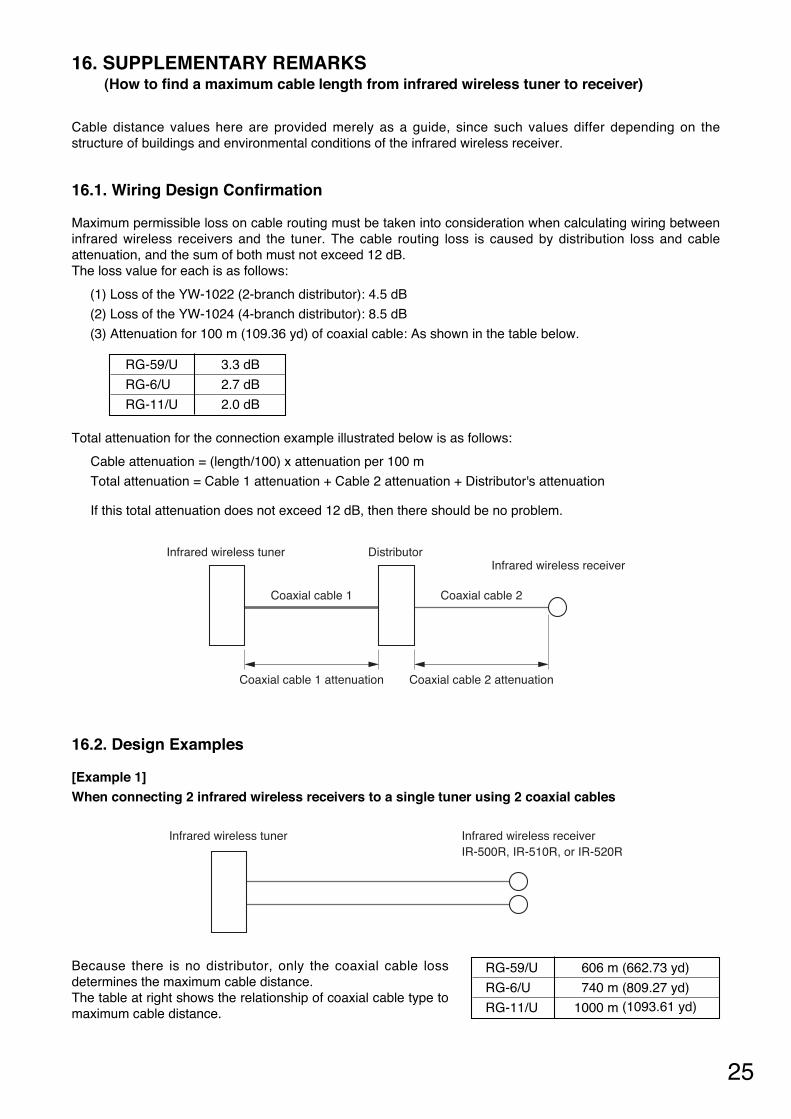
16.1. Wiring Design Confirmation
Maximum permissible loss on cable routing must be taken into consideration when calculating wiring betweeninfrared wireless receivers and the tuner. The cable routing loss is caused by distribution loss and cableattenuation, and the sum of both must not exceed 12 dB. The loss value for each is as follows:
(1) Loss of the YW-1022 (2-branch distributor): 4.5 dB
(2) Loss of the YW-1024 (4-branch distributor): 8.5 dB
(3) Attenuation for 100 m (109.36 yd) of coaxial cable: As shown in the table below.
RG-59/U 3.3 dB
RG-6/U 2.7 dB
RG-11/U 2.0 dB
Total attenuation for the connection example illustrated below is as follows:
Cable attenuation = (length/100) x attenuation per 100 m
Total attenuation = Cable 1 attenuation + Cable 2 attenuation + Distributor's attenuation
If this total attenuation does not exceed 12 dB, then there should be no problem.
Infrared wireless receiver
Coaxial cable 1 attenuation
Infrared wireless tuner
Coaxial cable 1
Distributor
Coaxial cable 2 attenuation
Coaxial cable 2
16.2. Design Examples
[Example 1]When connecting 2 infrared wireless receivers to a single tuner using 2 coaxial cables
Because there is no distributor, only the coaxial cable lossdetermines the maximum cable distance. The table at right shows the relationship of coaxial cable type tomaximum cable distance.
RG-59/U 606 m (662.73 yd)
RG-6/U 740 m (809.27 yd)
RG-11/U 1000 m (1093.61 yd)
Infrared wireless tuner Infrared wireless receiver IR-500R, IR-510R, or IR-520R
26
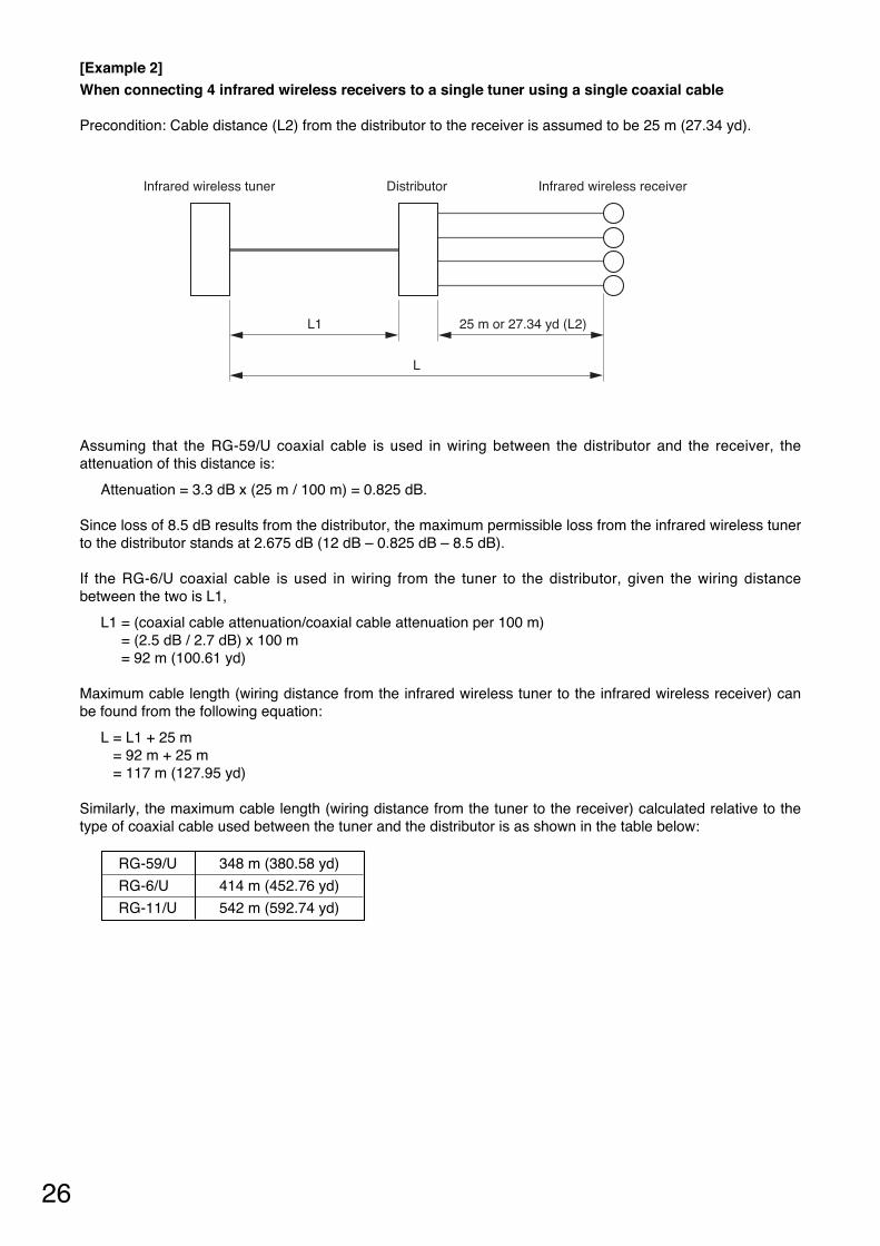
[Example 2] When connecting 4 infrared wireless receivers to a single tuner using a single coaxial cable
Precondition: Cable distance (L2) from the distributor to the receiver is assumed to be 25 m (27.34 yd).
Assuming that the RG-59/U coaxial cable is used in wiring between the distributor and the receiver, theattenuation of this distance is:
Attenuation = 3.3 dB x (25 m / 100 m) = 0.825 dB.
Since loss of 8.5 dB results from the distributor, the maximum permissible loss from the infrared wireless tunerto the distributor stands at 2.675 dB (12 dB – 0.825 dB – 8.5 dB).
If the RG-6/U coaxial cable is used in wiring from the tuner to the distributor, given the wiring distancebetween the two is L1,
L1 = (coaxial cable attenuation/coaxial cable attenuation per 100 m) = (2.5 dB / 2.7 dB) x 100 m = 92 m (100.61 yd)
Maximum cable length (wiring distance from the infrared wireless tuner to the infrared wireless receiver) canbe found from the following equation:
L = L1 + 25 m = 92 m + 25 m = 117 m (127.95 yd)
Similarly, the maximum cable length (wiring distance from the tuner to the receiver) calculated relative to thetype of coaxial cable used between the tuner and the distributor is as shown in the table below:
Infrared wireless tuner Infrared wireless receiverDistributor
L
L1 25 m or 27.34 yd (L2)
RG-59/U 348 m (380.58 yd)
RG-6/U 414 m (452.76 yd)
RG-11/U 542 m (592.74 yd)
27
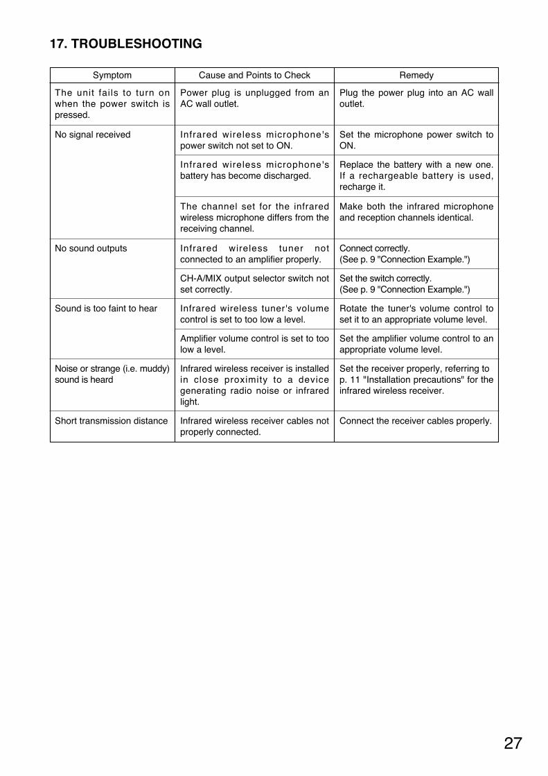
17. TROUBLESHOOTING
Symptom
The unit fai ls to turn onwhen the power switch ispressed.
Cause and Points to Check
Power plug is unplugged from anAC wall outlet.
Remedy
Plug the power plug into an AC walloutlet.
No signal received
Infrared wireless microphone'sbattery has become discharged.
Replace the battery with a new one.If a rechargeable battery is used,recharge it.
Sound is too faint to hear
Amplifier volume control is set to toolow a level.
Set the amplifier volume control to anappropriate volume level.
Infrared wireless microphone'spower switch not set to ON.
Set the microphone power switch toON.
The channel set for the infraredwireless microphone differs from thereceiving channel.
Make both the infrared microphoneand reception channels identical.
Infrared wireless tuner's volumecontrol is set to too low a level.
Rotate the tuner's volume control toset it to an appropriate volume level.
No sound outputs Infrared wireless tuner notconnected to an amplifier properly.
Connect correctly. (See p. 9 "Connection Example.")
CH-A/MIX output selector switch notset correctly.
Set the switch correctly. (See p. 9 "Connection Example.")
Noise or strange (i.e. muddy)sound is heard
Infrared wireless receiver is installedin close proximity to a devicegenerating radio noise or infraredlight.
Set the receiver properly, referring top. 11 "Installation precautions" for theinfrared wireless receiver.
Short transmission distance Infrared wireless receiver cables notproperly connected.
Connect the receiver cables properly.
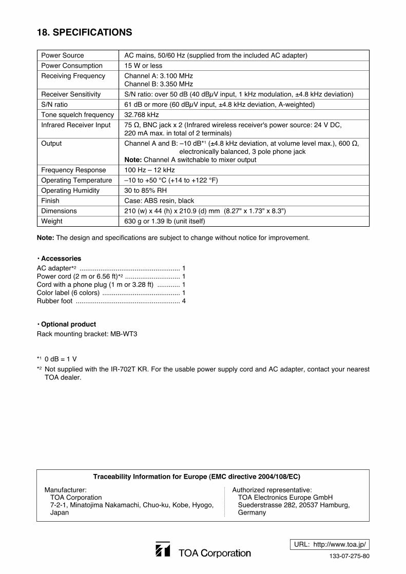
*1 0 dB = 1 V
*2 Not supplied with the IR-702T KR. For the usable power supply cord and AC adapter, contact your nearestTOA dealer.
133-07-275-80
URL: http://www.toa.jp/
18. SPECIFICATIONS
Note: The design and specifications are subject to change without notice for improvement.
• Accessories
Power Source AC mains, 50/60 Hz (supplied from the included AC adapter)
Power Consumption 15 W or less
Receiving Frequency Channel A: 3.100 MHzChannel B: 3.350 MHz
Receiver Sensitivity S/N ratio: over 50 dB (40 dBμV input, 1 kHz modulation, ±4.8 kHz deviation)
S/N ratio 61 dB or more (60 dBμV input, ±4.8 kHz deviation, A-weighted)
Tone squelch frequency 32.768 kHz
Infrared Receiver Input 75 Ω, BNC jack x 2 (Infrared wireless receiver's power source: 24 V DC, 220 mA max. in total of 2 terminals)
Output Channel A and B: –10 dB*1 (±4.8 kHz deviation, at volume level max.), 600 Ω, electronically balanced, 3 pole phone jack
Note: Channel A switchable to mixer output
Frequency Response 100 Hz – 12 kHz
Operating Temperature –10 to +50 °C (+14 to +122 °F)
Operating Humidity 30 to 85% RH
Finish Case: ABS resin, black
Dimensions 210 (w) x 44 (h) x 210.9 (d) mm (8.27" x 1.73" x 8.3")
Weight 630 g or 1.39 lb (unit itself)
AC adapter*2 ..................................................... 1Power cord (2 m or 6.56 ft)*2 ............................. 1Cord with a phone plug (1 m or 3.28 ft) ............ 1Color label (6 colors) ......................................... 1Rubber foot ....................................................... 4
• Optional productRack mounting bracket: MB-WT3
Traceability Information for Europe (EMC directive 2004/108/EC)
Manufacturer:TOA Corporation7-2-1, Minatojima Nakamachi, Chuo-ku, Kobe, Hyogo, Japan
Authorized representative:TOA Electronics Europe GmbHSuederstrasse 282, 20537 Hamburg,Germany