Infrared System Test and Evaluation at APL - CiteSeer
12
448 JOHNS HOPKINS APL TECHNICAL DIGEST, VOLUME 18, NUMBER 3 (1997) T Infrared System Test and Evaluation at APL Scott A. Gearhart and Kathryn K. Vogel he Applied Physics Laboratory’s legacy in radar systems dates back to World War II. By comparison, experience in infrared (IR) technology is quite recent, beginning at a low level in the 1970s and escalating in the 1980s. Interest in IR systems for naval area defense applications was prompted by the increasing sophistication of air threats and the potential benefit of rapid advances in IR technology. Today, a large portion of the Laboratory’s Navy mission work is IR systems. This article discusses the evolution and highlights of IR systems engineering, test, and evaluation capabilities at the Laboratory. (Keywords: Hardware-in-the-loop, Infrared, Seeker, Test facilities.) INTRODUCTION Infrared (IR) sensors have long played an important role in our country’s defense in diverse applications such as surveillance and early warning, aircraft and ground night-vision systems, and missile guidance. The Laboratory’s earliest exposure to IR sensors occurred about 1969 with several small-scale tasks associated with the High-Energy Laser Program, the Coherent Laser Radar Program, and the Rolling Airframe Missile Program. It was not until about 1980, however, that interest and efforts in IR systems work expanded. In the mid-1970s, threats against our surface ships were be- coming increasingly sophisticated, particularly in the area of radar jamming. A few visionaries at APL and elsewhere speculated that a combination of radar and IR guidance on a single defense missile would result in a significant tactical advantage. These queries into “dual-mode” guidance solutions spawned several feasi- bility studies, of which the most significant were the Wide-Area Guidance and Control Program, conducted from 1977 to 1983, and an advanced Standard Missile study conducted from 1980 to 1982. In anticipation of the important role for IR systems in advanced guidance applications, APL began to accumulate expertise in IR systems and their test and evaluation. Much of the existing test equipment was antiquated. Procurement and development of new test equipment proceeded slowly over several years (see Fig. 1). During this period, interest in dual-mode guidance systems grew slowly but steadily throughout the naval defense community. Once a clear need was established, the early exploratory preparations were instrumental in APL’s rapid response in developing state-of-the-art IR system evaluation tools and test assets. Today, through a period of phenomenal growth over the last decade, APL’s expertise in IR systems rivals that found anywhere. Figure 2 shows the growth of IR- related activities that now include dual-mode IR and RF test and evaluation facilities, modeling and simu- lation capabilities, field data collection systems, labo- ratories for characterizing and modeling IR optical ma- terials, and an aerothermal wind tunnel test facility. This article discusses the evolution and highlights of IR systems engineering, test, and evaluation capabili- ties at the Laboratory. It begins with advances in IR systems and their increasingly more stringent test re- quirements, and APL’s test and evaluation philosophy, OTHER TOPIC
Transcript of Infrared System Test and Evaluation at APL - CiteSeer

S. A. GEARHART AND K. K. VOGEL
OTHER TOPIC
T
Infrared System Test and Evaluation at APL
Scott A. Gearhart and Kathryn K. Vogel
he Applied Physics Laboratory’s legacy in radar systems dates back to World WarII. By comparison, experience in infrared (IR) technology is quite recent, beginning ata low level in the 1970s and escalating in the 1980s. Interest in IR systems for navalarea defense applications was prompted by the increasing sophistication of air threatsand the potential benefit of rapid advances in IR technology. Today, a large portion ofthe Laboratory’s Navy mission work is IR systems. This article discusses the evolutionand highlights of IR systems engineering, test, and evaluation capabilities at theLaboratory.(Keywords: Hardware-in-the-loop, Infrared, Seeker, Test facilities.)
INTRODUCTIONInfrared (IR) sensors have long played an important
role in our country’s defense in diverse applicationssuch as surveillance and early warning, aircraft andground night-vision systems, and missile guidance. TheLaboratory’s earliest exposure to IR sensors occurredabout 1969 with several small-scale tasks associatedwith the High-Energy Laser Program, the CoherentLaser Radar Program, and the Rolling Airframe MissileProgram. It was not until about 1980, however, thatinterest and efforts in IR systems work expanded. In themid-1970s, threats against our surface ships were be-coming increasingly sophisticated, particularly in thearea of radar jamming. A few visionaries at APL andelsewhere speculated that a combination of radar andIR guidance on a single defense missile would result ina significant tactical advantage. These queries into“dual-mode” guidance solutions spawned several feasi-bility studies, of which the most significant were theWide-Area Guidance and Control Program, conductedfrom 1977 to 1983, and an advanced Standard Missilestudy conducted from 1980 to 1982.
In anticipation of the important role for IR systemsin advanced guidance applications, APL began to
448 JOH
accumulate expertise in IR systems and their test andevaluation. Much of the existing test equipment wasantiquated. Procurement and development of new testequipment proceeded slowly over several years (see Fig.1). During this period, interest in dual-mode guidancesystems grew slowly but steadily throughout the navaldefense community. Once a clear need was established,the early exploratory preparations were instrumental inAPL’s rapid response in developing state-of-the-art IRsystem evaluation tools and test assets.
Today, through a period of phenomenal growth overthe last decade, APL’s expertise in IR systems rivals thatfound anywhere. Figure 2 shows the growth of IR-related activities that now include dual-mode IR andRF test and evaluation facilities, modeling and simu-lation capabilities, field data collection systems, labo-ratories for characterizing and modeling IR optical ma-terials, and an aerothermal wind tunnel test facility.This article discusses the evolution and highlights ofIR systems engineering, test, and evaluation capabili-ties at the Laboratory. It begins with advances in IRsystems and their increasingly more stringent test re-quirements, and APL’s test and evaluation philosophy,
NS HOPKINS APL TECHNICAL DIGEST, VOLUME 18, NUMBER 3 (1997)

which developed in response to these rapid advances.The article then summarizes the more innovative andsignificant APL test and evaluation accomplishments,and unique Laboratory test facilities. It concludes withfuture test needs and how the Laboratory is preparingto meet them.
ADVANCES IN IR GUIDANCESYSTEMS
The earliest IR systems application, beginning in the1950s, was guidance of air-to-air and ground-to-airdefense missiles. These early systems had single-ele-ment IR detectors, which were either optically ormechanically scanned to track targets, and used a man-in-the-loop for target identification and designation.Defense systems using this technology have proveneffective and are still in operation today. Advances inthe late 1960s through the 1970s included forward-looking IR systems, most of which used a linear arrayof IR detectors and scanning mirrors to produce animage for a human observer. These systems are still usedextensively on manned aircraft to facilitate nighttimeoperations. Similar technology is used for search andtrack systems. The latest revolution, which began inthe late 1970s, is IR focal plane arrays, which use a two-dimensional array of IR detectors, imaging optics, acryogenic cooling system, and readout electronics toproduce an image. These devices are the culminationof years of advances in IR detector technology and onlybecame commercially available about 1988. The use of
celerations have on the inertial sticantly, high velothe IR seeker’s prponents, which nif not adequatelyfailure. Indeed, scovers and activeover the IR doenvironments.
To meet these systems are becomcan no longer be guidance unit is aunit, a cryogenicform, power and csor. In turn, the system, namely, tpilot, the missile idownlink receiveradar). Given thisdata and sensor fto have knowled
The advancesperformance requern guidance systefacilities for evaluexample, applicattargets for testinrequire highly stments. In some r
Figure 1. Terry Harris and Randy Bruns conducting measurements on IR components inthe early 1980s.
JOHNS HOPKINS APL TECHNICAL DIGEST, VOLUME 18, NUMBER 3 (19
INFRARED SYSTEM TEST AND EVALUATION
IR focal plane arrays in defensemissiles is currently the cuttingedge of technology.
Applications of IR systems onlong-range and high-speed air de-fense missiles pose new technicalchallenges. Unlike earlier man-in-the-loop systems, more recent ap-plications require the guidance sys-tem to autonomously acquire andtrack targets. Other autonomousfunctions include discriminatingtargets from natural backgrounds,debris, and IR countermeasures, aswell as multiple-track processingand smart aimpoint selection. Thegreater detection sensitivity ofthese systems also increases clutter-induced false alarms that must bescreened with sophisticated proces-sors and algorithms. In addition,longer missile flight times, higherintercept altitudes, and higher ac-
placed more stringent requirementsabilization unit. Perhaps most signif-cities result in aerothermal heating ofotective dome and its internal com-ot only can degrade performance, but protected, can cause catastrophicome new systems require ejectable cooling (i.e., the flow of a coolant)me to survive the extreme flight
advanced requirements, IR guidanceing increasingly complex and thus
treated independently. A modern IR system composed of optics, a detectors supply, an inertially stabilized plat-ontrol electronics, and a data proces-IR guidance unit is part of a largerhe missile, which includes the auto-nertial reference unit, the uplink andrs, and auxiliary guidance units (e.g., complexity, and new possibilities for
usion, the IR systems engineer needsge of the missile system as a whole. in IR technology, the increase inirements, and the complexity of mod-ms have made devising tests and testating these systems challenging. Forions that required simple stationaryg are being replaced by those thatructured and dynamic IR environ-espects, the technical problems that
97) 449

S. A. GEARHART AND K. K. VOGEL
1970 1975 1980 1985 1990 1995 2000
TBD
TBD
TBD
IR guided projectile (new)
TBIP Program
IRES development
Dual-mode GSELdevelopment
IR seeker testing
IRTSdevelopment
MHIP Program
IR simulation
Wind tunnel testing
Seeker survey team
Low-dragwindowstudy
Laser radarexperiments
Wide-areaguidance study
RAM performanceanalyses
AdvancedSM study
Windtunnel
development
RAM Upgrade Program
Seeker selection panel
HPIRSProgram
IR seeker testing
EMD
Program
IR simulation
Dual-modeGSEL testing
Requirementsstudy
Small gyrotesting
Wind tunnel testing
SM-3 Program (new)
TBD
TBD
TBD
TBD
TBD
Year
RRFDProgram
Figure 2. The evolution of IR-related activities at APL. (EMD = engineering and manufacturing development, GSEL = Guidance SystemEvaluation Laboratory, HPIRS = high-performance IR seeker, IRES = IR environment simulator, IRTS = IR target simulator, MHIP = MissileHoming Improvement Program, RAM = rolling airframe missile, RRFD = risk reduction flight demonstration, SM = Standard Missile, TBD= to be determined.)
must be solved to address these test issues rival thoseassociated with developing the IR systems themselves.What is often overlooked is that advances in almostany technology proceed only in pace with advances intest and evaluation technology; otherwise, the criticalempirical data required to develop a new approach arelacking.
APL’S TEST AND EVALUATIONPHILOSOPHY
APL’s philosophy for IR test and evaluation has beenmolded not only by hands-on experience with IR sys-tems, but has evolved from a corporate “systems” legacythat precedes APL’s IR-related work. Some attributesof this philosophy are delineated as follows:
450 JOH
1. Aid in system development. Perform tests to verifysystem functionality and collect critical data neces-sary to system hardware and algorithm development.
2. Test incrementally. Perform tests first to characterizeperformance at the subsystem level (e.g., the IRseeker or inertial stabilization unit levels). Tests ofmultiple subsystems and their interactions are basedon experience gained at the subsystem level. A com-mon tendency is to begin testing at too high a level ofcomplexity (i.e., attempting a total end-to-end sys-tem test first). Problems seen at this high level oftesting are difficult to isolate.
3. Isolate problems and find solutions. Detect and isolateproblems in the system to reduce risk of failure in acostly missile flight test. Ensure the system meets itstactical requirements. Collaborate with the defensecontractor in defining and validating solutions.
NS HOPKINS APL TECHNICAL DIGEST, VOLUME 18, NUMBER 3 (1997)
INFRARED SYSTEM TEST AND EVALUATION
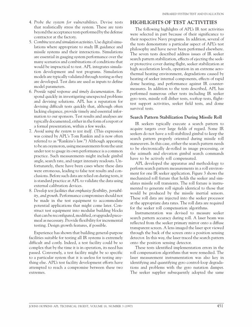
4. Probe the system for vulnerabilities. Devise teststhat realistically stress the system. These are testsbeyond the acceptance tests performed by the defensecontractor at the factory.
5. Combine test and simulation activities. Use digital simu-lations where appropriate to study IR guidance andmissile systems and their interactions. Simulationsare essential in gauging system performance over themany scenarios and combinations of conditions thatwould be impractical to test. APL integrates simula-tion development and test programs. Simulationmodels are typically validated through testing as theyare developed. Test data are used as inputs to definemodel parameters.
6. Provide rapid response and timely documentation. Re-spond quickly in investigating unexpected problemsand devising solutions. APL has a reputation fordevising difficult tests quickly that, although oftenlacking elegance, provide timely and essential infor-mation to our sponsors. Test results and analyses aretypically documented, either in the form of a report ora formal presentation, within a few weeks.
7. Avoid using the system to test itself. (This expressionwas coined by APL’s Tom Rankin and is now oftenreferred to as “Rankins’s law.”) Although appearingto be an oxymoron, using measurements from the unitunder test to gauge its own performance is a commonpractice. Such measurements might include gimbalangle, search rate, and target intensity readouts. Un-fortunately, there have been cases where these datawere erroneous, leading to false test results and con-clusions. Before such data are relied on during tests, itis standard practice at APL to validate the data usingexternal calibration devices.
8. Develop test facilities that emphasize flexibility, portabil-ity, and growth. Performance compromises should notbe made in the test equipment to accommodatepotential applications that might come later. Con-struct test equipment into modular building blocksthat can be reconfigured, modified, or upgraded piece-meal as necessary. Provide flexibility for incrementaltesting. Design growth features, if possible.
Experience has shown that building general-purposefacilities suitable for testing all IR systems is extremelydifficult and costly. Indeed, a test facility could be socomplex that by the time it is in operation, its need haspassed. Conversely, a test facility might be so specificto a particular system that it is useless for testing any-thing else. APL’s test facility development efforts haveattempted to reach a compromise between these twoextremes.
JOHNS HOPKINS APL TECHNICAL DIGEST, VOLUME 18, NUMBER 3 (1
HIGHLIGHTS OF TEST ACTIVITIESThe following highlights of APL’s IR test activities
were selected in part because of their significance totheir respective Navy programs. In addition, several ofthe tests demonstrate a particular aspect of APL’s testphilosophy and have never been performed elsewhere.The seven tests described address issues of IR seekersearch pattern stabilization, effects of ejecting the seek-er protective cover during flight, seeker stabilization athigh acceleration levels, operation in an extreme aero-thermal heating environment, degradations caused byheating of seeker internal components, effects of rapiddome heating, and performance against IR counter-measures. In addition to the tests described, APL hasperformed numerous other tests including IR seekergyro tests, missile roll dither tests, rooftop tests, flight-test support activities, seeker field tests, and domesurvival tests.
Search Pattern Stabilization During Missile RollIR seekers typically execute a search pattern to
acquire targets over large fields of regard. Some IRseekers do not have a roll-stabilized gimbal to keep thesearch pattern properly oriented during missile rollmaneuvers. In this case, either the search pattern needsto be electronically de-rolled in image processing, orthe azimuth and elevation gimbal search commandshave to be actively roll compensated.
APL developed the apparatus and methodology toperform search pattern measurements in a roll environ-ment for one IR seeker application. Figure 3 shows themechanized roll fixture that holds the seeker and sim-ulates missile roll transients. The roll fixture is instru-mented to generate roll signals identical to those thatwould be produced by the missile inertial sensors.These roll data are injected into the seeker processorat the appropriate data rates. The roll data are requiredfor the seeker roll compensation algorithms.
Instrumentation was devised to measure seekersearch pattern accuracy during roll. A laser beam wasreflected from the seeker primary mirror onto a diffusetransparent screen. A lens imaged the laser spot viewedthrough the back of the screen onto a position sensingdetector. In this way, the laser traced the search patternonto the position sensing detector.
These tests identified implementation errors in theroll compensation algorithms that were remedied. Thelaser measurement instrumentation was also key inidentifying and quantifying gyro control-loop degrada-tions and problems with the gyro nutation damper.The seeker supplier subsequently adopted the same
997) 451

S. A. GEARHART AND K. K. VOGEL
instrumentation and test procedures for developmentaltesting.
Cover Removal TransientsTesting revealed that a small free-gyro-stabilized IR
seeker might suffer significant transients in both spinspeed and reported gimbal angle upon ejection of itsprotective steel cover during flight. Transients observedin tests where the cover was removed by hand persistedfor a notable time, raising concerns about in-flightperformance degradations. To accurately measure thesetransients, APL constructed a unique apparatus toemulate in-flight cover ejection. The test apparatus wasdesigned to allow for controlled cover removal in lessthan 20 ms without damaging the seeker or cover.
Figure 4 shows the cover ejection apparatus. Theseeker and cover mounting structure are rigidly at-tached to a base plate. The cover is placed in positionover the seeker via the aft hinge and locked intoposition. Rather than using pyrotechnics to blow offthe cover, a series of aircraft bungee cords were at-tached to the forward end of the cover and stretched,using a winch mechanism to provide a representativeaerodynamic cover removal force and the desired coverremoval time. An impact-absorbing shield was placedin back of the seeker/cover assembly to prevent damageto the components. A simple hand-operated mecha-nism released the cover.
Tests were conducted to measure gyro spin speed andgimbal angle readout transients during cover removal.The results showed that removal of the steel cover canindeed cause transients in seeker pointing that can
measurements maand there was cterms could be linIn addition, even
Figure 3. Mechanized roll fixture used in search pattern fidelity tests. The roll positionreadout was input to the seeker processor to emulate missile inertial measurement data.
Winch toadjust
tension
Blow-awacover ovoperatin
seek
Figure 4. Apparatus
452 JOH
significantly delay the IR searchprocess. Simulation models wereupdated to reflect these time delays,and solutions for the cover transientproblem were recommended. Thesimple approach used for the coverremoval apparatus led to a rapid un-derstanding of the problem and,hence, possible solutions.
g-Sensitive Drift Tests Using aLinear Acceleration Sled
High accelerations (g) of ad-vanced missiles impose demandingg-sensitive drift requirements oninertial platforms. This situationwas of particular concern for oneseeker application that used com-pensation algorithms to negatedrift at high g levels. Constantsused in the compensation algo-rithm were derived from empirical
de in a 1-g laboratory environment,oncern whether the compensationearly extrapolated to higher g levels.if appropriate, it was unclear whether
Impactabsorber
Bungee cordsprovide coverremoval force
yerg
er
Release
to eject the seeker’s protective cover.
NS HOPKINS APL TECHNICAL DIGEST, VOLUME 18, NUMBER 3 (1997)

1-g tests in the laboratory were sensitive enough toensure that the algorithms were properly implemented.To measure seeker drift at higher accelerations, APLdesigned and built a servo-controlled linear accelera-tion sled, which was used to test the seeker againstsinusoidal accelerations with amplitudes up to ±4 g.
The sled is shown in Fig. 5 along with the IR seeker,control electronics, and various other support equip-ment. The sled track is approximately 10 ft long withthe total travel of the seeker approaching 5 ft. Theseeker is mounted on the sled so that its longitudinal axisis perpendicular to the acceleration input. The sled waslocated on the roof of a five-story building. While ac-celerated, the seeker was commanded to track a station-ary target (an industrial-sized heater) approximately 3mi away, and gyro drift data were recorded. Results fromthe sled tests verified the seeker supplier’s g-sensitivedrift measurements and compensation methodology.
Aerothermal Testing of an IR SeekerAn IR seeker was tested at APL’s W. H. Avery
Advanced Technology Development Laboratory in theCell 4 wind tunnel. Cell 4 produces supersonic flow atthe temperatures and pressures required for aerodynam-ic heating representative of missile flight. (A latersection of the article provides a description of the Cell4 wind tunnel.) The tests evaluated seeker performancein a hostile thermal, vibration, and electrical environ-ment before flight testing. The specific test objectives
were first to collecgate scan modulatlimit target acquisers. (Scan modulaing section.) A seseeker through a pto demonstrate bawas optically relaseeker to attempt
Operating an IRenvironment was that the seeker coflight-like environscan modulation dnamically heated source for scan movided the impetusinstrumented seek
Laser Heating ofSeeker
The distinguishis the optical traingyroscopic action viously, one perfofree-gyro IR seekersignal artifacts supoutputs associatedseeker application
Seeker viewsa distantIR source
Seeker
Sled motion
Figure 5. Seeker mounted on a linear acceleration sled used in g-sensitive driftmeasurements.
JOHNS HOPKINS APL TECHNICAL DIGEST, VOLUME 18, NUMBER 3 (19
INFRARED SYSTEM TEST AND EVALUATION
t IR detector waveforms to investi-ion, a phenomenon that can greatlyition performance in free-gyro seek-tion will be described in the follow-cond objective was to transition thereprogrammed functional sequence
sic functionality. Finally, a test targetyed into the wind tunnel for the acquisition and track.
seeker in a supersonic aerothermala significant first. The tests proveduld survive and function in a severement. In addition, for the first time,ata were collected for a real aerody-dome. As a result, a new potentialdulation was discovered, which pro- for further study, including tests ofers to measure internal temperatures.
Components in a Free-Gyro IR
ing feature of a free-gyro IR seeker spun at a high rate to produce thefor stabilization. As mentioned pre-rmance degradation mechanism ofs is scan modulation, which refers toerimposed on the detector voltage
with the spinning gyro. In past IRs, scan modulation was primarilyattributable to electromagneticpickup. In advanced applicationswhere extreme aerothermal heat-ing is present, scan modulationis primarily an optical/stray-lightphenomenon that can be orders ofmagnitude higher than the electro-magnetic contribution.
The wind tunnel tests describedin the preceding section revealedscan modulation higher than an-ticipated, suggesting that hot inter-nal seeker components could be aleading contributor in addition tothe hot dome. To isolate and quan-tify scan modulation contributions,tests were performed to selectivelyheat internal seeker components.1
In one test configuration, an argonlaser was used to selectively heatcomponents within the seekerwhile it was operating, and scanmodulation waveforms were re-corded. Temperature data were re-corded using a thermal imager. Inanother test configuration, a CO2
97) 453
S. A. GEARHART AND K. K. VOGEL
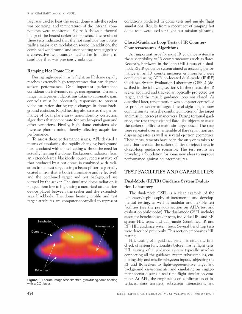
laser was used to heat the seeker dome while the seekerwas operating, and temperatures of the internal com-ponents were monitored. Figure 6 shows a thermalimage of the heated seeker components. The results ofthese tests indicated that the hot sunshade was poten-tially a major scan modulation source. In addition, thecombined wind tunnel and laser heating tests suggesteda convective heat transfer mechanism from dome tosunshade that was previously unknown.
Ramping Hot Dome TestDuring high-speed missile flight, an IR dome rapidly
reaches extremely high temperatures that can degradeseeker performance. One important performanceconsideration is dynamic range management. Dynamicrange management algorithms (akin to automatic gaincontrol) must be adequately responsive to preventvideo saturation during rapid changes in dome back-ground emission. Rapid heating also stresses the perfor-mance of focal plane array nonuniformity correctionalgorithms that compensate for pixel-to-pixel gain andoffset variations. Finally, high dome emissions alsoincrease photon noise, thereby affecting acquisitionperformance.
To assess these performance issues, APL devised ameans of emulating the rapidly changing backgroundflux associated with dome heating without the need foractually heating the dome. Background radiation froman extended-area blackbody source, representative ofthat produced by a hot dome, is combined with radi-ation from a test target using a beamsplitter (a partiallycoated mirror that is both transmissive and reflective),and the combined target and hot background areviewed by the seeker. The simulated dome radiation isramped from low to high using a motorized attenuationdevice placed between the seeker and the extended-area blackbody. The dome heating profile and testtarget attributes are computer-controlled to represent
Sunshade
Dome
Edge guard
Primary mirror
Figure 6. Thermal image of seeker free-gyro during dome heatingwith a CO2 laser.
454 JOHN
conditions predicted in dome tests and missile flightsimulations. Results from a recent set of ramping hotdome tests were used for flight test mission planning.
Closed-Guidance Loop Tests of IR Counter-Countermeasures Algorithms
An important issue for most IR guidance systems isthe susceptibility to IR countermeasures such as flares.Recently, hardware-in-the-loop (HIL) tests of a dual-mode RF/IR guidance system aimed at assessing perfor-mance in an IR countermeasures environment wereconducted using APL’s co-located dual-mode (IR/RF)Guidance System Evaluation Laboratory (GSEL) (de-scribed in the following section). In these tests, the IRseeker acquired and tracked an optically projected testtarget, and the missile guidance loop was closed. Asdescribed later, target motion was computer controlledto produce seeker-to-target line-of-sight angle ratescommensurate with the combined motion of the targetand missile intercept maneuvers. During terminal guid-ance, the test target ejected flare-like objects to assessthe seeker’s ability to maintain target track. The testswere repeated over an ensemble of flare separation anddispensing rates as well as several ejection geometries.These measurements have been the only ones taken todate that assessed the seeker’s ability to reject flares inclosed-loop guidance scenarios. The test results areproviding a foundation for some new ideas to improveperformance against countermeasures.
TEST FACILITIES AND CAPABILITIES
Dual-Mode (RF/IR) Guidance System Evalua-tion Laboratory
The dual-mode GSEL is a clear example of theLaboratory’s philosophy of incremental and develop-mental testing, as well as modular and flexible testfacilities (see the previous section on APL’s test andevaluation philosophy). The dual-mode GSEL includesassets for benchtop seeker tests, individual IR- and RF-system HIL tests, and dual-mode (combined IR andRF) HIL guidance system tests. Several benchtop testswere described previously. This section emphasizes HILtesting.
HIL testing of a guidance system is often the finalcheck of system functionality before missile flight tests.HIL testing of a guidance system typically involvesconnecting all the guidance system subassemblies, em-ulating ship and missile subsystem inputs, subjecting theRF and IR seekers to flight-representative target andbackground environments, and emulating an engage-ment scenario using a real-time flight simulation com-puter. At APL, the emphasis is on confirmation of in-terfaces, data transfers, subsystem interactions, and
S HOPKINS APL TECHNICAL DIGEST, VOLUME 18, NUMBER 3 (1997)

INFRARED SYSTEM TEST AND EVALUATION
functional sequences. The characteristics of the guid-ance system homing loop are also examined. In manycases, APL’s HIL test program has identified subtle al-gorithm and software coding errors not detected at otherlevels of testing. Subtle anomalies like these, such as amissing negative sign in a coordinate transformation,can have costly consequences in a missile flight test.
A major challenge of dual-mode guidance systemtesting is adequately emulating both IR and RF flightenvironments. APL’s early successes at dual-mode test-ing used an electrically connected configuration inwhich the missile RF guidance system was mounted inan anechoic chamber in front of an array of horns thatsimulated the target radar return, sea-surface clutter,and countermeasures. The IR seeker and its signalprocessor were removed from the guidance section andplaced in a separate facility that optically projected thetarget and background images. The IR seeker processorwas reconnected to the guidance section via a longtransmission line. The HIL flight simulation computersynchronously controlled the RF and IR environmentgenerators according to the engagement scenario.
Having the IR and RF seekers located in separatetest locations affords one advantage—the test environ-ments for each seeker can be more complex than whatcould be achieved with the two seekers integrated andtested in a common facility where space constraints areprohibitive. For example, in the electrically connectedconfiguration, the IR seeker could be mounted on a rateor vibration table while environments are viewed
JOHNS HOPKINS APL TECHNICAL DIGEST, VOLUME 18, NUMBER 3 (1
through an IR projector. In addition, in this configu-ration, there are no worries that the IR generationequipment might affect the fidelity of the RF simula-tion, and vice versa. For these reasons, the electricallyconnected configuration continues to be important forAPL’s HIL test activities, particularly for those aimedat system development. Clearly, however, the necessityof removing the IR seeker from the guidance system isinvasive and not desirable for preflight checkout andproduction assurance testing. To provide an alternativeconfiguration that precludes disassembly of the guid-ance system, the Laboratory constructed the co-locateddual-mode IR/RF GSEL.2,3
The co-located dual-mode IR/RF GSEL layout isshown in Fig. 7. The guidance system, including the IRseeker, is mounted in an anechoic chamber in front ofan RF linear array. IR environments are generatedoutside the chamber and optically relayed to the inte-rior. A periscope provides the optical interface to theIR seeker. As shown in the figure, the co-located dual-mode GSEL is designed for testing guidance systemswith the RF seeker in the missile nose and the IR seekermounted on the missile side.
The design challenges for the co-located dual-modeGSEL were numerous and included providing adequatevibration isolation as well as getting IR radiation intothe anechoic chamber without RF leakage. The mostdifficult constraint was the limited-size envelope forthe IR generation system, which greatly influenced thedesign approach. For example, IR relay optics inside the
Missile controlpanel
(keyboard)
Initializationunit
Inertialreference unit
simulatorRF targetand ECM
signalgenerators
IRradiation
Chamberentry port
IR seeker
Guidancesystem
RF lineararray and
switch tree
RF anechoicchamber
RF seekerRF target
Uplinksimulator
Display unit
Guidancesection dataacquisition
IRES
Flex 32real-time
simulationcomputer
IREScontroller
Programmablepower supplies
Real-time SystranSCRAMNet interface
RF
Cable trunk system
RF arraycontroller
Control andmonitor station
Figure 7. Co-located dual-mode hardware-in-the-loop test configuration. (IRES = IR environment simulator,ECM = electronic countermeasures.)
997) 455

S. A. GEARHART AND K. K. VOGEL
NS HOPKINS APL TECHNICAL DIGEST, VOLUME 18, NUMBER 3 (1997)
456 JOHchamber were required to be be-hind the RF seeker antenna withan adequate margin for RF shield-ing, as well as fit in the space avail-able below the guidance system.Conflicting with this requirementwas the desire for flexibility in in-jecting the IR radiation into the IRseeker over a large angular range.Many design iterations were re-quired to find a compromise be-tween these requirements. In addi-tion, the bulk of the IR generationequipment outside the chamberhad to fit into a tight-size envelopeto keep optical relay paths as shortas possible. Analysis showed thatlonger paths would have greatlyreduced the optical performance ofthe system. Providing a projectionsystem that displays sufficientlycomplex environments and also fitsinto a tight-size envelope is perhaps the most ambitiousoptomechanical development task attempted at APL.Appropriately, the IR Environment Simulator (IRES)is the subject of the next section.
The IR Environment SimulatorThe IRES is a computer-controlled optomechanical
system that projects IR targets, backgrounds, and coun-termeasures. The chief design goal for the IRES wasachieving good optical performancewhile maintaining compactness andmodularity. As mentioned previous-ly, compactness was a prime con-cern for application to the co-locat-ed dual-mode GSEL. Modularitywas important because of the desirefor a general-purpose test resourcethat could be moved and assembledin various configurations, includingelectrically connected HIL tests andseeker bench tests.
The starting point for the designof the IRES was the IR target sim-ulator (IRTS) constructed in themid-1980s. Although the IRTSserved its intended function well, itwas too large. Figure 8 shows thatthe IRTS, which projected a singlemoving target and a backgroundscene, occupied a 4 × 12 ft opticalbench. The IRES requirement wasto use approximately the same
IRT
Seeker undertest
Figure 8. The IR targa 4 × 12 ft optical ben
TarBackground gener
Figure 9. Seeker betarget and backgroun
space used for two targets, the background scene, anda suite of relay optics. One key to minimizing the IRESsize envelope was the use of small scanning mirrors asopposed to large linear slide tables used in the IRTS tomove the targets. In addition, optical paths were foldedand layered in two planes, and lens design was opti-mized to reduce component dimensions. Figure 9 showsthe reduction in scale achieved for one IRES targetgenerator. Here, several IRES modules are configuredfor benchtop seeker testing.
S outputlens
et simulator (IRTS) developed in the mid-1980s. The IRTS occupiesch.
get generatorator
Seeker under test
Relay optics
nchtop testing using the IR environment simulator (IRES) closingd generators.

INFRARED SYSTEM TEST AND EVALUATION
Figure 10. The IR environment simulator (IRES) configured for co-located dual-modeGuidance System Evaluation Laboratory testing. (a) The optics outside the anechoicchamber. (b) The periscope mounted on a rotary table. (IRCM = IR countermeasures.)
Figure 10a shows the IRES fully configured for co-located GSEL testing. The prime components includea closing target generator, a point target/IR counter-measures generator, a static background scene genera-tor, an optical relay module, and a periscope inside theanechoic chamber. Figure 10b shows the periscopemounted on a rotary table that allows IRES inputs tobe injected into the seeker over a +45° azimuthal range.Outputs from each component are combined withbeamsplitters. The IRES is transmissive in the 3- to 5-mm wavelength band.
Materials and SOptical prope
guidance system decade, APL has dependent opticaes, and surfaces mance, developitest conditions. Mrials and Spectroseral spectrometerand data acquisi
(a)
(b)
Supportstand
leg
Point target/IRCMgenerator
Backgroundtransparency
fixture
Chamberoptical
interface
Forwardfold
mirror
Pathof IRradiation
Optical relaymodule
Beamsplitter
Movingbackgroundgenerator Closing target
generator
IR seekerlocation
Periscope
Path ofIR radiation
Rotarytable
Guidancesectionsupportstand
IR cameraused for test
JOHNS HOPKINS APL TECHNICAL DIGEST, VOLUME 18, NUMBER 3 (
pectroscopy Laboratoryrties of materials are important inperformance evaluation. For the pastmeasured and modeled temperature-l properties of windows, coolant gas-for use in calculating seeker perfor-ng evaluation facilities, and setting
easurements are made in the Mate-copy Laboratory, which includes sev-s, lasers, test cells, vacuum systems,tion and processing capabilities for
complete optical properties char-acterization as well as remote sens-ing and biomedical applications.
Seeker windows in high-speedmissiles are exposed to considerableheating. Window thermal emis-sion is a crucial factor that affectsseeker noise, dynamic range, non-uniformity compensation, and scanmodulation performance, as well asradiative heat transfer to internalseeker components. To characterizetransparent materials, APL has de-veloped techniques to measuretemperature-dependent transmis-sion4 (to infer emission at lowertemperatures) and emission5 up to2000 K. Other measurements sup-porting window characterizationinclude the temperature depen-dence of the refractive index6 andscatter properties,7 particularly ofpolycrystalline materials. Measure-ments are incorporated in widelyused optical property models,8 in-cluding the commercially availableOPTIMATR software, and stan-dard references.9,10
Emission and reflectance prop-erties of opaque materials are alsomeasured and developed into an-gular- and frequency-dependentdescriptions of optical properties.Such descriptions are used withaerodynamic, heat transfer, andgeometric viewing to develop tar-get signatures and own-missile self-emission models.
The W. H. Avery AdvancedTechnology DevelopmentLaboratory
The Avery Laboratory’s Cell 4wind tunnel is used for experimental
1997) 457

S. A. GEARHART AND K. K. VOGEL
evaluation of IR seekers and components in high-en-ergy flow fields representative of missile flight.11 Theprincipal components of the facility include a Mach 5nozzle, a hydrogen combustion heater, a test cabin, anda downstream exhaust diffuser, which result in a 10-in-dia. flow field that can be heated to temperatures ashigh as 2222 K. An injection unit allows IR compo-nents to be inserted into the airstream after flow con-ditions have been established. Several windows in thesides of the test chamber provide for access of collimat-ed IR sources and cameras for optical measurements.
Cell 4 has been used to test IR seeker componentsin a natural progression: first domes, mounting mate-rials, and blow-off covers; then seeker mock-ups; andfinally real operating seekers. Significant accomplish-ments to date include investigations of thermal shockcapabilities of IR dome materials, internal seeker tem-peratures and vibration, cover removal methodologies,IR dome cooling techniques, IR seeker survivabilityand functionality, IR seeker scan modulation, and aero-optical effects. So far, over 800 IR-related tests havebeen performed in Cell 4. Of these, about 150 testswere performed to examine dome-cooling performancealone. Figure 11 shows a seeker dome being tested inthe wind tunnel.
(a)
(b)
Figure 11. Dome-cooling tests in the W. H. Avery AdvancedTechnology Development Laboratory. (a) No cooling. (b) Heliumforward cooling.
458 JOH
IR Image Data Acquisition and AnalysisAPL has designed and configured a specialized cam-
era system to collect radiometrically calibrated clutterdata in the midwave band. In one application, IR mea-surements of the marine environment were taken tostudy infrared seeker performance, develop and testimage-processing algorithms, statistically characterizeclutter, and validate an APL-developed ocean cluttersynthesis model. In other applications, the system wasused for collecting IR imagery of ground structures andclutter to better understand diurnal and climaticvariations.
The camera system consists of two portable instru-ment pallets. The first pallet includes a 256 × 256Cincinnati Electronics focal plane array camera thatoperates in a variety of subbands in the 3- to 5-mmwaveband. This camera and a commercial 8-mm videocamera are mounted on a DC servo-driven elevation-over-azimuth pointing head. A local computer digitallycontrols the cameras and servos and collects imagedata. A second pallet is connected via local area net-work and video coaxial lines. Distributed signal- andimage-processing software manages the automated datacollection task, as well as displays and analyzes the dataat the time of collection.
The compactness of this system allows for easy trans-portation and fast setup, and also meets small spacerequirements. Field test exercises initially includedocean clutter measurements from offshore and at sea.They have now been extended to missile and targetsignatures and desert clutter measurements.12
CONCLUSIONEven as test facilities are completed, more stringent
test requirements arise. Constant reevaluation andupgrading of capabilities are needed in today’s defensecommunity environment. For example, recent IR sys-tems applications will require highly structured anddynamic IR test environments. APL is well into theplanning phase to develop the appropriate facilities totest these systems. Figure 12 shows an image from thenewest innovation of IR test technology, the resistorarray scene projector. APL is acquiring such a devicein 1997.
APL does not develop facilities for the sake of test-ing; rather, we test to help develop systems for oursponsors. There are no dedicated test engineers. Often,the same personnel who perform design trades, developsimulations, and interact with the sponsors are thesame ones who devise, conduct, analyze, and documentthe tests. Enough cannot be said for intimately under-standing the system to be tested. This should always beour emphasis and priority.
NS HOPKINS APL TECHNICAL DIGEST, VOLUME 18, NUMBER 3 (1997)

INFRARED SYSTEM TEST AND EVALUATION
Figure 12. An IR image projected with a resistive heater sceneprojector. (Photo provided courtesy of Alan Pritchard of BritishAerospace’s Sowerby Research Center.)
REFERENCES1Howser, L. M. , “Measuring and Modeling Scan Modulation of an Infrared
Seeker,” Johns Hopkins APL Tech. Dig. 16(1), 27–33 (1995).2Gearhart, S. A., Harris, T. J., Kardian, C. J., Prendergast, D. T., and Winters,
D. T., “A Hardware-in-the-Loop Test Facility for Dual-Mode Infrared andRadar Guidance Systems,” in Targets and Backgrounds: Characterization andRepresentation, Wendell R. Watkins and Dieter Clement (eds.), Proc. SPIE2469, 170–180 (1995).
3 O’Bannon, T. E., and Gearhart, S. A., “Dual-Mode Infrared and RadarHardware-in-the-Loop Test Assets at The Johns Hopkins University AppliedPhysics Laboratory,” in Technologies for Synthetic Environments: Hardware-in-the-Loop Testing, Robert L. Murer, Jr. (ed.), Proc. SPIE 2741, 332–346 (1996).
JOHNS HOPKINS APL TECHNICAL DIGEST, VOLUME 18, NUMBER 3 (1
4Thomas, M. E., Joseph, R. I., and Tropf, W. J., “Infrared TransmissionProperties of Sapphire, Spinel, Yttria, and ALON as a Function ofTemperature and Frequency,” Appl. Opt. 27, 239–245 (1988).
5Sova, R. M., Linevsky, M. J., Thomas, M. E., and Mark, F. F.,“High-Temperature Optical Properties of Oxide Ceramics,” Johns HopkinsAPL Tech. Dig. 13(3), 368–378 (1992).
6Lange, C. H., and Duncan, D. D., “Temperature Coefficients of theRefractive Index for Candidate Optical Windows,” Johns Hopkins APL Tech.Dig. 14(1), 12–15 (1993).
7Duncan, D. D., Lange, C. H., and Fisher, D. G., “Imaging Performance ofCrystalline and Polycrystalline Oxides,” Johns Hopkins APL Tech. Dig. 14(1),4–11 (1993).
8Thomas, M. E., “Temperature Dependence of the Complex Index ofRefraction,” in Handbook of Optical Constants of Solids II, E. D. Palik (ed.),Academic Press, pp. 177–201 (1991).
9Tropf, W. J., Thomas, M. E., and Harris, T. J., “Properties of Crystals andGlasses,” Chap. 33, in Handbook of Optics, 2nd Ed., McGraw Hill, New York(1994).
10Tropf, W. J., Thomas, M. E., and Klocek, P., “Infrared Optical Materials,” inCritical Reviews of Optical Science and Technology: Inorganic Optical Materials,SPIE, Bellingham, WA, pp. 137–169 (1996).
11Tropf, W. J., Thomas, M. E., Harris, T. J., and Lutz, S. A., “Performance ofOptical Sensors in Hypersonic Flight,” Johns Hopkins APL Tech. Dig. 8(4),370–385 (1987).
12Constantikes, K., Thomas, M., and Claussen, E., “Diurnal Variations ofDesert Midwave Images,” Johns Hopkins APL Tech. Dig. 17(4), 357–361(1996).
ACKNOWLEDGMENTS: We extend our thanks to Emily Claussen, KimConstantikes, and Bill Tropf, who provided material for this article. Special thanksgo to Randy Bruns, Tom Rankin, and Bill Tropf, who were the pioneers of IRsystems work at APL and still direct many of the activities. Other early contributorsinclude Stan Gordon, Joe Gulick, Bob Hires, Roger Lapp, Dick Marlow, JamesMiller, Russ Rollin, Fred Schenkel, and Irv Schoeder. More recent contributorsinclude Adam Bulharowski, Michael Elko, Kelly Frazer, Terry Harris, Jim Hemler,Terry Hipp, Linda Howser, Charles Kardian, Ken Kitzman, Steve Lutz, Mark Mayr,Craig Mitchell, Mike Neuenhoff, Tom O’Bannon, Dan Prendergast, Gary Shiflett,Richard Steinberg, Mike Thomas, Eric Tissue, Ed Weedon, Kelly West, and DuaneWinters. We apologize for any inadvertent omissions.
THE AUTHORS
SCOTT A. GEARHART is a Principal Professional Staff engineer in theElectro-Optical Systems Group of the Air Defense Systems Department. Hereceived a B.S. degree in engineering science from the Pennsylvania StateUniversity in 1982 and an M.S. degree in electrical engineering from TheUniversity of Maryland in 1987. Mr. Gearhart joined APL in 1983 and hasworked primarily on the development and evaluation of optical and infraredsensors for guidance and surveillance applications. He has also participated inIR&D efforts in optical radar processing and laser remote sensing, as well asbiomedical studies of laser angiography and laser Doppler velocimetry ofsimulated blood flow. His e-mail address is [email protected].
KATHRYN K. VOGEL is a Senior Professional Staff engineer in the Electro-Optical Systems Group of the Air Defense Systems Department. She received aB.S. degree from Drexel University in 1983 and an M.S. degree from The JohnsHopkins University in 1988, both in electrical engineering. Since joining APLin 1983, Ms. Vogel has worked on the test, evaluation, and simulation of infraredand inertial systems primarily for missile guidance. Her experience includescoordinating IR seeker test activities, analysis of laboratory and flight data, seekerperformance evaluation, inertial component testing, and modeling and simula-tion of IR seeker dynamics and inertial systems. Currently, she is involved in thedevelopment of a terminal seeker for a gun-launched munition. Her e-mailaddress is [email protected].
997) 459