Influence of structural heterogeneity of high-strength ...
7
Influence of structural heterogeneity of high-strength OCTG tubes on sulfide corrosion cracking resistance. Artem Davydov 1* , Andrey Zhitenev 1 , Natalya Devyaterikova 2 , Konstantin Laev 2 1 Peter the Great St. Petersburg Polytechnic University, St. Peterburg, Russia 2 JSC Pervouralsk New Pipe Plant, Pervouralsk, Russia *E-mail: [email protected] Keywords: High-strength OCTG, Sulfide corrosion cracking, sulfide stress corrosion tests with low strain rates (SSRT), microstructure, banding, segregation Abstract. High-strength OCTG tubes like C110, according to API 5CT (yield strength at least 758 MPa), are subject to requirements in terms of mechanical and corrosion properties. In this work, we studied the influence of seamless tubes microstructure with a 177.8 mm diameter and 10.36 mm wall thickness of class С110 high-strength steel to sulfide stress corrosion cracking (SSC) and sulfide stress corrosion cracking with low strain rates (SSRT). Tubes were obtained from continuous billets by screw piercing with preliminary quenching and tempering. It was established that cracking during the tests always begins from the inner surface of the tube. Rough segregation bands were found on the inner tube surface, which occupies about a third of the thickness. It is shown that the SSRT assessment technique allows to estimate the threshold value of the resistance. Introduction During development of deep oil and gas fields, casing is influenced not only by the aggressive environment of the well (H2S and CO2), but high pressures and temperatures [1-4]. If low-alloyed steel pipes are exposed to these environments, hydrogen cracking can occur, caused corrosion cracks in the hydrogen sulfide environment (SSC) [5]. Casing of high-strength groups in a corrosion-resistant design used for those conditions, for example C110 according to ANSI/API 5CT (yield strength at least 758 MPa) [6, 7]. Extreme operating conditions require the high quality of the steels and determine the requirements for the level of alloying and purity for detrimental impurities, as well as for the chemical and structural homogeneity of the finished pipes. Therefore, to produce these pipes, it is important to choose the optimal chemical composition of steel and consider that the formation of the final structure is influenced by all redistributions from smelting and casting [8] to rolling [9] and final heat treatment [10]. At satisfactory mechanical properties, determined under static tension, local weak points arise due to non-metallic inclusions and segregations of chemical elements, which can lead to SSC in a corrosive environment (Figure 1, [11]). Near a surface defect (nonmetallic inclusions, solid structural components), pitting may occur [12, 13], hydrogen accumulates, which is then adsorbed, diffuses into the steel, and leads to its embrittlement [11-13]. If segregations and defects are developed into the depth of the pipe, then further opening and development of a corrosion crack occurs along them [11]. Due to the large number of potential causes of steel fracture during tests on SSC, a detailed study of each specific case is required to determine the causes of test failures and to develop technological recommendations to minimize them.
Transcript of Influence of structural heterogeneity of high-strength ...

Influence of structural heterogeneity of high-strength OCTG tubes on sulfide corrosion cracking
resistance.
Artem Davydov1*, Andrey Zhitenev1, Natalya Devyaterikova2, Konstantin Laev2
1Peter the Great St. Petersburg Polytechnic University, St. Peterburg, Russia 2JSC Pervouralsk New Pipe Plant, Pervouralsk, Russia
*E-mail: [email protected]
Keywords: High-strength OCTG, Sulfide corrosion cracking, sulfide stress corrosion tests
with low strain rates (SSRT), microstructure, banding, segregation
Abstract.
High-strength OCTG tubes like C110, according to API 5CT (yield strength at least 758
MPa), are subject to requirements in terms of mechanical and corrosion properties. In this
work, we studied the influence of seamless tubes microstructure with a 177.8 mm diameter
and 10.36 mm wall thickness of class С110 high-strength steel to sulfide stress corrosion
cracking (SSC) and sulfide stress corrosion cracking with low strain rates (SSRT). Tubes
were obtained from continuous billets by screw piercing with preliminary quenching and
tempering. It was established that cracking during the tests always begins from the inner
surface of the tube. Rough segregation bands were found on the inner tube surface, which
occupies about a third of the thickness. It is shown that the SSRT assessment technique
allows to estimate the threshold value of the resistance.
Introduction
During development of deep oil and gas fields, casing is influenced not only by the aggressive
environment of the well (H2S and CO2), but high pressures and temperatures [1-4]. If low-alloyed steel
pipes are exposed to these environments, hydrogen cracking can occur, caused corrosion cracks in the
hydrogen sulfide environment (SSC) [5]. Casing of high-strength groups in a corrosion-resistant design
used for those conditions, for example C110 according to ANSI/API 5CT (yield strength at least 758 MPa)
[6, 7].
Extreme operating conditions require the high quality of the steels and determine the requirements for
the level of alloying and purity for detrimental impurities, as well as for the chemical and structural
homogeneity of the finished pipes. Therefore, to produce these pipes, it is important to choose the optimal
chemical composition of steel and consider that the formation of the final structure is influenced by all
redistributions from smelting and casting [8] to rolling [9] and final heat treatment [10].
At satisfactory mechanical properties, determined under static tension, local weak points arise due to
non-metallic inclusions and segregations of chemical elements, which can lead to SSC in a corrosive
environment (Figure 1, [11]). Near a surface defect (nonmetallic inclusions, solid structural components),
pitting may occur [12, 13], hydrogen accumulates, which is then adsorbed, diffuses into the steel, and leads
to its embrittlement [11-13]. If segregations and defects are developed into the depth of the pipe, then
further opening and development of a corrosion crack occurs along them [11].
Due to the large number of potential causes of steel fracture during tests on SSC, a detailed study of
each specific case is required to determine the causes of test failures and to develop technological
recommendations to minimize them.

Figure 1. SSC mechanism in high-strength OCTG [9]
In this work, we studied the influence of seamless tubes microstructure with a 177.8 mm diameter and
10.36 mm wall thickness of class С110 high-strength steel 0,3C-Cr-Mn-Mo+0,15(V+Nb+Ti) to sulfide
stress corrosion cracking (SSC) and sulfide stress corrosion cracking with low strain rates (SSRT) [14].
Tubes were obtained from continuous billets by screw piercing with preliminary quenching and tempering.
Materials and research methods
Samples were tested for resistance to SSC according to NACE TM0177 [14] and API 5CT [7]
requirements for strength group C110 – exposure in 100% hydrogen sulfide for 720 hours at a load of
644 MPa.
As additional studies, the samples were tested at various loads to determine the threshold stress: at 50,
62.5, and 75% of the minimum standard yield strength (MSYS) of 758 MPa. All samples, except those
tested at 75% load, showed resistance to SSC (Figure 2).
50%, 720 hours 62,5%, 720 hours 75%, 160 hours 85%, 96 hours 85%, 96 hours
Figure 2. Samples after SSC testing
The study of the corrosion resistance by the SSRT method was carried out using a universal machine
UM-10T with an installed reduction gearbox, which allows stretching at speeds from 8.7·10-8 s-1 to
8.7·10–4 s-1 [14]. Mechanical properties were determined using a universal testing machine UM-10T using standard
cylindrical fivefold samples. The macro-hardness of the pipe under study was determined on a transverse
template using a TK-2M hardness machine by the Rockwell method.
Longitudinal specimens were cut from the pipe and from the tested samples, which were then ground
and polished. Then etching with 4% nitric acid. Metallographic studies were performed using a Reichter
light optical microscope equipped with a Thixomet automatic image analyzer. The microhardness of
individual structural components was determined using a microhardness tester according to the Vickers
method with loads from 1 to 180 g.
The analysis of the dispersed structure and determination of the local chemical composition were studied
using a Zeiss Supra scanning electron microscope equipped with an attachment for X-ray spectral analysis.
Results
Mechanical properties
Testing was made on three cylindrical samples taken from different OCTG quadrants in accordance with
GOST 1497. The test results are presented in Table 1. It presents the yield strength YS, tensile strength TS,
elongation and hardness HRC of the studied samples.

Table 1. Mechanical properties of the OCTG samples.
Sample YS, MPa TS, MPa elongation, % YS/TS Hardness, HRC
1 795 878 18.7 0.90 26.0
2 785 875 19.1 0.89 26.5
3 800 880 20.1 0.90 26.0
GOST 31446 758-828 >793 18.0 0.86 <30.0
According to the results of mechanical tests, the material of the OCTG pipe sample corresponds to
the strength class C110 (ANSI/API 5CT).
Metallographic analysis
The fracture surface of the samples after testing on SSC at 85% of the yield strength was studied using
SEM (Figure 3). Crack nucleation on the samples always occurred from side marked in red, followed by a
ductile rupture zone (yellow) and a break zone. The fracture structure in Figure 3a has a brittle fracture.
The structure of Figure 3b has numerous ductile fracture pits, which is typical for crack growth zones, the
structure of Figure 3c is similar to the previous one, but it has multiple secondary cracks, which corresponds
to the break fracture zone.
Fracture surface, ×2000
Figure 3. Fracture surface of the specimen after testing on SSC 85% YSmin
For metallographic studies, longitudinal thin sections (along the dashed line in Figure 3) were cut out
from the samples after testing on the SSC so that the fracture surface fell into the thin section. A panoramic
view of the structure of the reverse part of the sample is shown in Figure 4.
а
b
c
а
b
c

Panoramic image, ×50 Panoramic image, ×200
Figure 4. Fracture surface of the specimen after testing on SSC
Dark segregation bands were found on the sample, occupying about a third of the surface on the side of
the inner pipe surface. It is from this surface that the destruction of samples always begins during tests on
the SSC. Also, the secondary cracks located perpendicular to the axis of the specimen, according to the
stress state diagram during testing, as they develop and meet the segregation band, unfold parallel to the
specimen axis.
The structure of OCTG samples is composed of tempered martensite and sorbite (Figure 5a). An
inhomogeneity was also found along the pipe wall thickness in the form of segregation bands located at the
inner surface and occupying about a third of the thickness (Figure 5b).
Outer surface of OCTG, × 1000 Inner surface of OCTG, × 1000
Figure 5. OCTG structure at the inner and outer surfaces
This crude structural heterogeneity results in different properties across the pipe, as measured by
hardness. Closer to the outer surface of the pipe, the hardness is lower than that of the central part but is
within the permissible divergence (about 30 HV). It is important to note that closer to the inner surface,
there is an unevenness in hardness caused by the presence of segregation bands. The hardness between the
structural inhomogeneities differs by 40 - 50 HV0.18, and in the bands, themselves reaches 325 HV0.18.
Figure 6 shows the structure of the material in dark (left) and bright (right) bands.
(Nb,Ti)xCyNz
а b

×500
×500
×10000
×10000
×25000
×25000
Figure 6. OCTG structure in dark (left) and bright (right) bands
The structure in the segregation bands is more dispersed and contains many small non-metallic
inclusions. According to the results of the chemical analysis of the dark and light bands presented in Table 2
and Figure 7, it was determined that in the segregation areas there is an increased content of molybdenum,
chromium, and silicon, inherited from the zonal segregations in the central part of the continuous casting.
Figure 7. Chemical composition in dark and bright bands
Table 2. Chemical composition, wt. %
Element Dark band Bright band
Spectrum 1 Spectrum 2
Si 0.42 0.32
Cr 1.29 0.96
Mn 0.88 0.93
Fe 95.99 97.07
Mo 1.42 0.71
Bright Dark
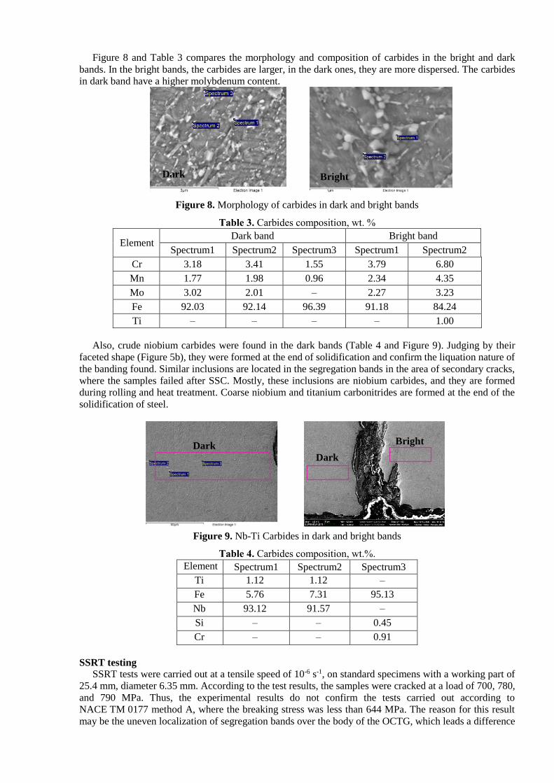
Figure 8 and Table 3 compares the morphology and composition of carbides in the bright and dark
bands. In the bright bands, the carbides are larger, in the dark ones, they are more dispersed. The carbides
in dark band have a higher molybdenum content.
Figure 8. Morphology of carbides in dark and bright bands
Table 3. Carbides composition, wt. %
Element Dark band Bright band
Spectrum1 Spectrum2 Spectrum3 Spectrum1 Spectrum2
Cr 3.18 3.41 1.55 3.79 6.80
Mn 1.77 1.98 0.96 2.34 4.35
Mo 3.02 2.01 – 2.27 3.23
Fe 92.03 92.14 96.39 91.18 84.24
Ti – – – – 1.00
Also, crude niobium carbides were found in the dark bands (Table 4 and Figure 9). Judging by their
faceted shape (Figure 5b), they were formed at the end of solidification and confirm the liquation nature of
the banding found. Similar inclusions are located in the segregation bands in the area of secondary cracks,
where the samples failed after SSC. Mostly, these inclusions are niobium carbides, and they are formed
during rolling and heat treatment. Coarse niobium and titanium carbonitrides are formed at the end of the
solidification of steel.
Figure 9. Nb-Ti Carbides in dark and bright bands
Table 4. Carbides composition, wt.%.
Element Spectrum1 Spectrum2 Spectrum3
Ti 1.12 1.12 –
Fe 5.76 7.31 95.13
Nb 93.12 91.57 –
Si – – 0.45
Cr – – 0.91
SSRT testing
SSRT tests were carried out at a tensile speed of 10-6 s-1, on standard specimens with a working part of
25.4 mm, diameter 6.35 mm. According to the test results, the samples were cracked at a load of 700, 780,
and 790 MPa. Thus, the experimental results do not confirm the tests carried out according to
NACE TM 0177 method A, where the breaking stress was less than 644 MPa. The reason for this result
may be the uneven localization of segregation bands over the body of the OCTG, which leads a difference
Dark Bright
Dark
Dark Bright

in conditions between the tested samples. Further testing and research is required to investigate these
discrepancies and are currently in progress.
Conclusions
The reasons for the initiation of cracks on specimens of high-strength steel (strength group C110) after
SSC testing are determined. The main reason for the destruction of samples is the presence of segregation
banding (dark and bright bands of different degrees of tempering), localized on one of the sides of the
sample, along which destruction occurs. Further investigation of the samples from the pipe showed that the
banding is localized at the inner surface of the pipe. The dark bands have increased hardness in comparison
with bright ones (320 and 280 HV, respectively), and an increased content of chromium, molybdenum and
niobium. In addition to dispersed niobium, molybdenum and chromium carbides formed during rolling and
heat treatment, coarse niobium and titanium carbonitrides were found in the bands, which were formed in
the solidifying metal due to liquation phenomena. Further testing and research with SSRT method is
required to investigate these discrepancies and are currently in progress.
References
[1] Study of corrosion behavior of carbon and low-alloy steels in CO2-containing environments,
Kostitsyna, I., Shakhmatov, A., Davydov, A., E3S Web Conf., 121 (2019) 04006, DOI:
10.1051/e3sconf/201912104006
[2] Failure analysis of plunger rod and barrel of sucker rod pumps D. Strekalovskaya, A. Davydov, D.
Lyashenko, Tleshev, Maxat 10.24247/ijmperdjun20201414
[3] Natalya Devyaterikova, Marianna Nurmukhametova, Aleksandr Kharlashin, Yegor Popov Types of
corrosion damage of tubing in the oilfield E3S Web of Conferences 121, 03001 (2019)
[4] Ermakov B.S, Alhimenko A.A., Shaposhnikov N.O., Tsvetkov A.S., Shirokov A.V., Study of the
crystallographic texture of pipe steel // Letters on Materials Volume 10, Issue 1, February 2020, Pages 48-
53
[5] Peculiarities of corrosion cracking of high-strength pipe steels in hydrogen sulfide environment
A.Alkhimenko, B. Ermakov, E. Alekseeva, S. Mushnikova 10.24247/ijmperdjun20201446
[6] Patent RU 2719618 C1 S. Aleksandrov, K. Laev, I. Shcherbakov, N. Devyaterikova, G. Oshurkov,
K. Rogova, A. Pavlov, I. Rodionova Hot-rolled seamless tubing with increased operational reliability for
oil-field equipment
[7] ANSI/API Specification 5CT «Specification for Casing and Tubing»
[8] A. G. Shiryaeva, S. G. Chetverikovb, S. G. Chikalova, I. Yu. Pyshmintsevc and P. V. Krylovd
Production of Seamless Steel Pipe for Oil and Gas Extractionin Challenging Conditions // Steel in
Translation, 2018, Vol. 48, No. 11, pp. 704–711
[9] Tihe Zhou, Peng Zhang, Kate Kuuskman, Erminio Cerilli, Kashif Rehman, Sang-Hyun Cho, Dan
Burella Development of Medium-High Carbon Casing/Tubing for Direct Strip Production Complex
(DSPC) // Contributed Papers from Materials Science and Technology 2016 (MS&T16)
[10] E. A. Putilova, S. M. Zadvorkin, E. S. Gorkunov, I. N. Veselov, and I. Y. Pyshmintsev (2019)
Investigation of structure and properties of low-carbon low-alloyed Cr-Mo pipe steel intended for operating
in sour environment // AIP Conference Proceedings 2167, 020291 (2019)
[11] T. Omura, M. Numata, T. Takayama, Y. Arai (2015) Super-high Strength Low Alloy Steel OCTG
with Improved Sour Resistance // Nippon Steel & Sumitomo Metal Technical Report No. 107 February
2015. P18-23
[12] Sankara Papavinasam CorrMagnet Consulting Inc., Ottawa, ON, Canada Pitting corrosion 28 // Trends
in Oil and Gas Corrosion Research and Technologies
[13] Lekan Taofeek Popoola, Alhaji Shehu Grema, Ganiyu Kayode Latinwo, Babagana Gutti & Adebori
Saheed Balogun Corrosion problems during oil and gas production and its mitigation // International Journal
of Industrial Chemistry volume 4, Article number: 35 (2013)
[14] A. Alhimenko, A. Kharkov, B. Shemyakinskiy, N. Shaposhnikov Development of the methodology of
accelerated testing of oil-gas pipe steels for stress corrosion cracking 2020 Zavodskaya Laboratroiya.
Diagnostika Materialov 86(9):70-76
[15] NACE TM 0177 Laboratory Testing of Metals for Resistance to Sulfide Stress Cracking and Stress
Corrosion Cracking in H2S Environments.