Influence of Input Parameters on the Characteristics of...
8
Strojniški vestnik - Journal of Mechanical Engineering 57(2011)9, 689-696 Paper received: 14.02.2011 DOI:10.5545/sv-jme.2011.035 Paper accepted: 08.06.2011 *Corr. Author’s Address: Tabriz University, Department of Mechanical Engineering, Tabriz, Iran, [email protected] 689 Influence of Input Parameters on the Characteristics of the EDM Process Shabgard, M. – Seyedzavvar, M. – Oliaei, S.N.B. Mohammadreza Shabgard 1,* – Mirsadegh Seyedzavvar 1 – Samad Nadimi Bavil Oliaei 2 1 Department of Mechanical Engineering, University of Tabriz, Iran 2 Department of Mechanical Engineering, Middle East Technical University, Turkey This paper presents the results of experimental studies carried out to conduct a comprehensive investigation on the influence of Electrical Discharge Machining (EDM) input parameters on the characteristics of the EDM process. The studied process characteristics included machining features, embracing material removal rate, tool wear ratio, and arithmetical mean roughness, as well surface integrity characteristics comprised of the thickness of white layer and the depth of heat affected zone of AISI H13 tool steel as workpiece. The experiments performed under the designed full factorial procedure, and the considered EDM input parameters included pulse on-time and pulse current. The results of this study could be utilized in the selection of optimum process parameters to achieve the desired EDM efficiency, surface roughness, and surface integrity when machining AISI H13 tool steel. ©2011 Journal of Mechanical Engineering. All rights reserved. Keywords: electrical discharge machining, material removal rate, tool wear ratio, surface roughness, white layer thickness, depth of heat affected zone 0 INTODUCTION Considering the challenges brought on by advanced technology, the Electrical Discharge Machining (EDM) process is one of the best alternatives for machining an ever increasing number of high-strength, non-corrosion, and wear resistant materials [1] and [2]. AISI H13 tool steel is considered as a significant material that has a widespread application in mold industries [3]. Electrical discharge machining utilizes rapid, repetitive spark discharges from a pulsating direct-current power supply between the workpiece and the tool submerged into a dielectric liquid [4]. The thermal energy of the sparks leads to intense heat conditions on the workpiece causing melting and vaporizing of the workpiece material. Due to a high temperature of the sparks, not only work material is melted and vaporized, but the electrode material is also melted and vaporized, which is known as tool wear. The tool wear process is quite similar to the material removal mechanism of the workpiece as the tool and the workpiece are considered as a set of electrodes in the EDM process. Due to this wear, tool loses its dimensions resulting in inaccurate cavities formed on the workpiece. Consequently, during the EDM process, the main machining output parameters are the material removal rate (MRR), tool wear ratio (TWR) and surface roughness (R a ) of the workpiece. It is desirable to obtain the maximum MRR with minimum TWR and surface roughness [5]. Furthermore, at the end of each discharge, depending on the plasma flushing efficiency (% PFE) or the ability of plasma channel in removing molten material from the molten material crater, collapsing of the plasma channel causes very violent suction and severe bulk boiling of some molten material and removing them from the molten crater [6]. The material remained in the crater re-solidifies, which is called the “white layer” or “recast layer”, and develops a residual stress that often causes micro cracks. An annealed Heat Affected Zone (HAZ) lay directly below the recast layer. The micro cracks created in the white layer could penetrate into the HAZ. Additionally, this layer is softer than the underlying base material. This annealed zone could weaken prematurely and cause the material to develop stress fractures that could lead to anything from a minor malfunction to a catastrophic failure. Since the quality of an ED machined surface is becoming more and more important to satisfy the increasing demands of sophisticated component performance, longevity and reliability [7] and
Transcript of Influence of Input Parameters on the Characteristics of...
Strojniški vestnik - Journal of Mechanical Engineering 57(2011)9, 689-696 Paper received: 14.02.2011DOI:10.5545/sv-jme.2011.035 Paper accepted: 08.06.2011
*Corr. Author’s Address: Tabriz University, Department of Mechanical Engineering, Tabriz, Iran, [email protected] 689
Influence of Input Parameters on the Characteristics of the EDM Process
Shabgard, M. – Seyedzavvar, M. – Oliaei, S.N.B.Mohammadreza Shabgard1,* – Mirsadegh Seyedzavvar1 – Samad Nadimi Bavil Oliaei2
1Department of Mechanical Engineering, University of Tabriz, Iran 2Department of Mechanical Engineering, Middle East Technical University, Turkey
This paper presents the results of experimental studies carried out to conduct a comprehensive investigation on the influence of Electrical Discharge Machining (EDM) input parameters on the characteristics of the EDM process. The studied process characteristics included machining features, embracing material removal rate, tool wear ratio, and arithmetical mean roughness, as well surface integrity characteristics comprised of the thickness of white layer and the depth of heat affected zone of AISI H13 tool steel as workpiece. The experiments performed under the designed full factorial procedure, and the considered EDM input parameters included pulse on-time and pulse current. The results of this study could be utilized in the selection of optimum process parameters to achieve the desired EDM efficiency, surface roughness, and surface integrity when machining AISI H13 tool steel. ©2011 Journal of Mechanical Engineering. All rights reserved.Keywords: electrical discharge machining, material removal rate, tool wear ratio, surface roughness, white layer thickness, depth of heat affected zone
0 INTODUCTION
Considering the challenges brought on by advanced technology, the Electrical Discharge Machining (EDM) process is one of the best alternatives for machining an ever increasing number of high-strength, non-corrosion, and wear resistant materials [1] and [2]. AISI H13 tool steel is considered as a significant material that has a widespread application in mold industries [3].
Electrical discharge machining utilizes rapid, repetitive spark discharges from a pulsating direct-current power supply between the workpiece and the tool submerged into a dielectric liquid [4]. The thermal energy of the sparks leads to intense heat conditions on the workpiece causing melting and vaporizing of the workpiece material. Due to a high temperature of the sparks, not only work material is melted and vaporized, but the electrode material is also melted and vaporized, which is known as tool wear. The tool wear process is quite similar to the material removal mechanism of the workpiece as the tool and the workpiece are considered as a set of electrodes in the EDM process. Due to this wear, tool loses its dimensions resulting in inaccurate cavities formed on the workpiece. Consequently, during the EDM process, the main machining
output parameters are the material removal rate (MRR), tool wear ratio (TWR) and surface roughness (Ra) of the workpiece. It is desirable to obtain the maximum MRR with minimum TWR and surface roughness [5].
Furthermore, at the end of each discharge, depending on the plasma flushing efficiency (% PFE) or the ability of plasma channel in removing molten material from the molten material crater, collapsing of the plasma channel causes very violent suction and severe bulk boiling of some molten material and removing them from the molten crater [6]. The material remained in the crater re-solidifies, which is called the “white layer” or “recast layer”, and develops a residual stress that often causes micro cracks. An annealed Heat Affected Zone (HAZ) lay directly below the recast layer. The micro cracks created in the white layer could penetrate into the HAZ. Additionally, this layer is softer than the underlying base material. This annealed zone could weaken prematurely and cause the material to develop stress fractures that could lead to anything from a minor malfunction to a catastrophic failure. Since the quality of an ED machined surface is becoming more and more important to satisfy the increasing demands of sophisticated component performance, longevity and reliability [7] and
Strojniški vestnik - Journal of Mechanical Engineering 57(2011)9, 689-696
690 Shabgard, M. – Seyedzavvar, M. – Oliaei, S.N.B.
[8], the optimum utilization of the EDM process requires the selection of an appropriate set of machining parameters that would result in the minimum thickness of the recast layer and depth of heat affected zone [9].
This paper aims to fill the gap in the existing literature with respect to the processing of AISI H13 tool steel with EDM. In particular, EDM machining experiments were conducted on AISI H13 samples having a hardness of 52.7 HRC using copper electrode to investigate the correlations between the EDM parameters (pulse on-time and current) and the EDM characteristics of such a workpiece. The output factors investigated were the material removal rate, tool wear ratio, surface roughness, as well as the thickness of white layer and depth of heat affected zone of EDMed workpiece. This experimental study results in the selection of optimum process parameters to achieve the desired EDM efficiency, surface roughness, and surface integrity when machining such a workpiece material.
1 EXPERIMENTAL SETUP AND PROCEDURE
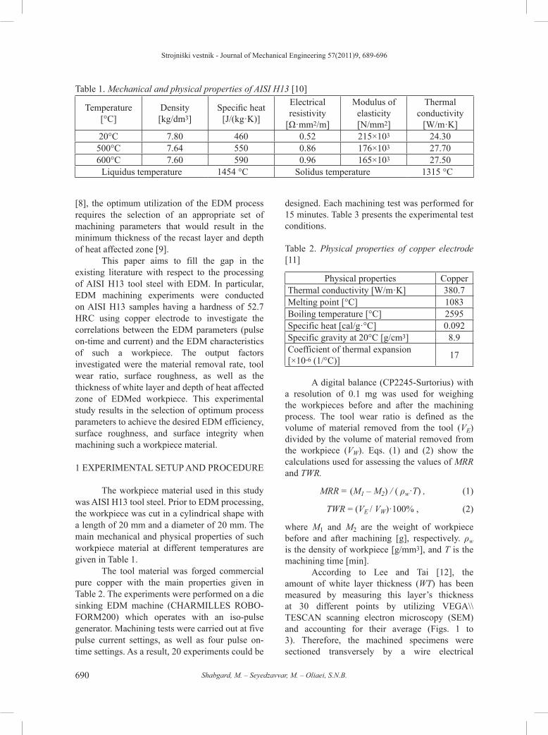
The workpiece material used in this study was AISI H13 tool steel. Prior to EDM processing, the workpiece was cut in a cylindrical shape with a length of 20 mm and a diameter of 20 mm. The main mechanical and physical properties of such workpiece material at different temperatures are given in Table 1.
The tool material was forged commercial pure copper with the main properties given in Table 2. The experiments were performed on a die sinking EDM machine (CHARMILLES ROBO-FORM200) which operates with an iso-pulse generator. Machining tests were carried out at five pulse current settings, as well as four pulse on-time settings. As a result, 20 experiments could be
designed. Each machining test was performed for 15 minutes. Table 3 presents the experimental test conditions.
Table 2. Physical properties of copper electrode [11]
Physical properties CopperThermal conductivity [W/m·K] 380.7Melting point [°C] 1083Boiling temperature [°C] 2595Specific heat [cal/g·°C] 0.092Specific gravity at 20°C [g/cm3] 8.9Coefficient of thermal expansion [×10-6 (1/°C)] 17
A digital balance (CP2245-Surtorius) with a resolution of 0.1 mg was used for weighing the workpieces before and after the machining process. The tool wear ratio is defined as the volume of material removed from the tool (VE) divided by the volume of material removed from the workpiece (VW). Eqs. (1) and (2) show the calculations used for assessing the values of MRR and TWR.
MRR = (M1 – M2) / ( ρw·T) , (1)
TWR = (VE / VW)·100% , (2)
where M1 and M2 are the weight of workpiece before and after machining [g], respectively. ρw is the density of workpiece [g/mm3], and T is the machining time [min].
According to Lee and Tai [12], the amount of white layer thickness (WT) has been measured by measuring this layer’s thickness at 30 different points by utilizing VEGA\\TESCAN scanning electron microscopy (SEM) and accounting for their average (Figs. 1 to 3). Therefore, the machined specimens were sectioned transversely by a wire electrical
Table 1. Mechanical and physical properties of AISI H13 [10]
Temperature[°C]
Density[kg/dm3]
Specific heat[J/(kg·K)]
Electrical resistivity
[Ω·mm2/m]
Modulus of elasticity[N/mm2]
Thermal conductivity
[W/m·K]20°C 7.80 460 0.52 215×103 24.30
500°C 7.64 550 0.86 176×103 27.70600°C 7.60 590 0.96 165×103 27.50
Liquidus temperature 1454 °C Solidus temperature 1315 °C
Strojniški vestnik - Journal of Mechanical Engineering 57(2011)9, 689-696
691Influence of Input Parameters on the Characteristics of the EDM Process
discharge machine and prepared under a standard procedure for metallographic observation. Etching was performed by immersing the specimens in 5% Nital reagent.
Table 3. Experimental test conditions
Generator type Iso-pulse (ROBOFORM 200)
Dielectric fluid Oil Flux ELF2Flushing type Normal submerged
Power supply voltage [V] 200
Reference voltage [V] 70Pulse current [A] 8; 12; 16; 20; 24
Polarity PositivePulse on-time [µs] 12.8; 25; 50; 100Pulse interval [µs] 6.4
Tool material Commercial pure copper
Tool shapeCylindrical
(Ø18.3 mm and L=20 mm)
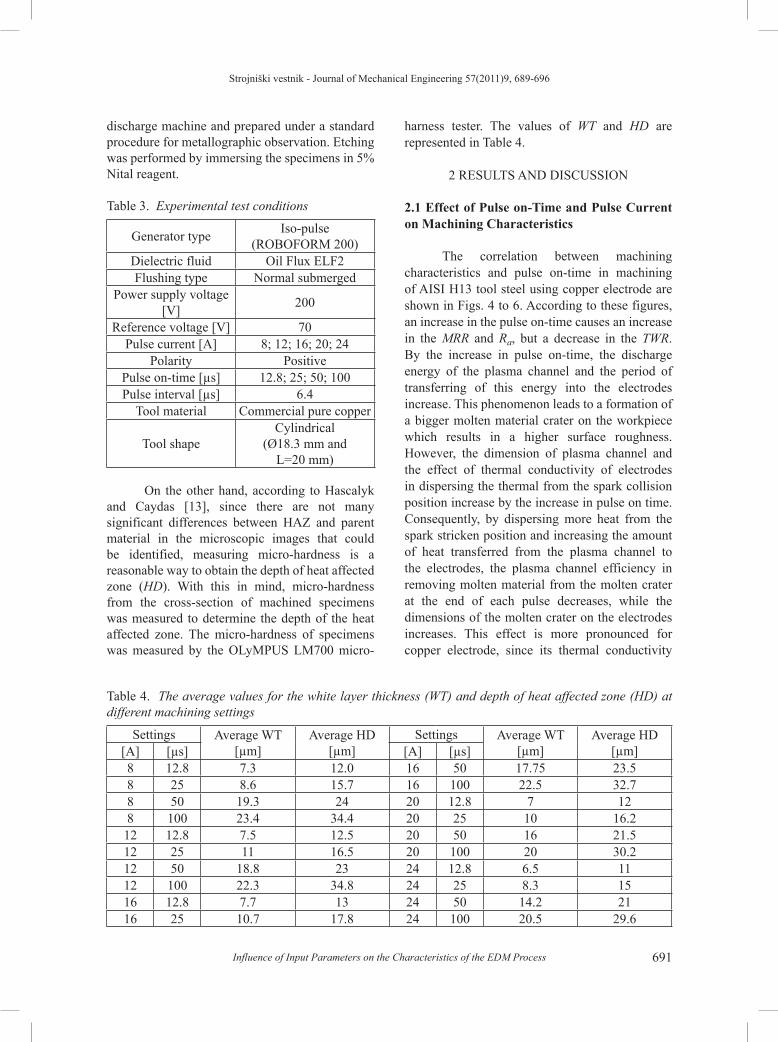
On the other hand, according to Hascalyk and Caydas [13], since there are not many significant differences between HAZ and parent material in the microscopic images that could be identified, measuring micro-hardness is a reasonable way to obtain the depth of heat affected zone (HD). With this in mind, micro-hardness from the cross-section of machined specimens was measured to determine the depth of the heat affected zone. The micro-hardness of specimens was measured by the OLyMPUS LM700 micro-
harness tester. The values of WT and HD are represented in Table 4.
2 RESULTS AND DISCUSSION
2.1 Effect of Pulse on-Time and Pulse Current on Machining Characteristics
The correlation between machining characteristics and pulse on-time in machining of AISI H13 tool steel using copper electrode are shown in Figs. 4 to 6. According to these figures, an increase in the pulse on-time causes an increase in the MRR and Ra, but a decrease in the TWR. By the increase in pulse on-time, the discharge energy of the plasma channel and the period of transferring of this energy into the electrodes increase. This phenomenon leads to a formation of a bigger molten material crater on the workpiece which results in a higher surface roughness. However, the dimension of plasma channel and the effect of thermal conductivity of electrodes in dispersing the thermal from the spark collision position increase by the increase in pulse on time. Consequently, by dispersing more heat from the spark stricken position and increasing the amount of heat transferred from the plasma channel to the electrodes, the plasma channel efficiency in removing molten material from the molten crater at the end of each pulse decreases, while the dimensions of the molten crater on the electrodes increases. This effect is more pronounced for copper electrode, since its thermal conductivity
Table 4. The average values for the white layer thickness (WT) and depth of heat affected zone (HD) at different machining settings
Settings Average WT [µm]
Average HD [µm]
Settings Average WT [µm]
Average HD [µm][A] [µs] [A] [µs]
8 12.8 7.3 12.0 16 50 17.75 23.58 25 8.6 15.7 16 100 22.5 32.78 50 19.3 24 20 12.8 7 128 100 23.4 34.4 20 25 10 16.212 12.8 7.5 12.5 20 50 16 21.512 25 11 16.5 20 100 20 30.212 50 18.8 23 24 12.8 6.5 1112 100 22.3 34.8 24 25 8.3 1516 12.8 7.7 13 24 50 14.2 2116 25 10.7 17.8 24 100 20.5 29.6

Strojniški vestnik - Journal of Mechanical Engineering 57(2011)9, 689-696
692 Shabgard, M. – Seyedzavvar, M. – Oliaei, S.N.B.
is much higher than that of the workpiece. As a result, tool wear ratio decreases by increase in pulse on-time.
Figs. 7 to 9 show that MRR, TWR, and Ra increase with augments of the pulse current. Such results were expected as it is obvious that a higher current causes a stronger spark, which results in more eroded material for both electrodes.
Fig. 1. SEM micrograph showing the white layer of EDMed workpiece (I = 8 A and Ti = 25 µs)
Fig. 2. SEM micrograph showing the white layer of EDMed workpiece (I = 24 A and Ti = 50 µs)
Fig. 3. SEM micrograph showing the white layer of EDMed workpiece (I = 24 A and Ti = 100 µs)
At a low current, a small quantity of heat is generated and a substantial portion of it is absorbed by the surroundings. As a result, the amount of utilized energy in melting and vaporizing the electrodes is not so intense. However, with an increase in pulse current and with a constant amount of pulse on-time, a stronger spark with higher thermal energy is produced [14], and a substantial quantity of heat will be transferred into the electrodes. Furthermore, as the pulse current increases, discharge strikes the surface of the sample more intensely, and creates an impact force on the molten material in the crater and causes more molten material to be ejected out of the crater, so the surface roughness of the machined surface increases.
2.2 Effect of Pulse on-Time and Pulse Current on Surface Integrity
The increase in the thickness of white layer and depth of heat affected zone by the increase in pulse on-time can be clearly seen from the experimental results (Figs. 10 and 11). The justification for this phenomenon is that the plasma flushing efficiency has a strict effect on the white layer thickness. With an increase in pulse on-time, plasma flushing efficiency decreases.

Strojniški vestnik - Journal of Mechanical Engineering 57(2011)9, 689-696
693Influence of Input Parameters on the Characteristics of the EDM Process
Fig. 4. MRR vs. pulse on-time
Fig. 5. TWR vs. pulse on-time
Fig. 6. Ra vs. pulse on-time
Fig. 7. MRR vs. pulse current
Fig. 8. TWR vs. pulse current
Fig. 9. Ra vs. pulse current

Strojniški vestnik - Journal of Mechanical Engineering 57(2011)9, 689-696
694 Shabgard, M. – Seyedzavvar, M. – Oliaei, S.N.B.
As a result, the ability of plasma channel for ejecting the molten material from the molten puddle decreases. Subsequently, this remained molten material in the molten puddle re-solidifies forming a white layer upon the machined surface. Furthermore, the increase of discharge duration increases the amount of the conducted heat into the workpiece during each discharge, and consequently, more underlying material is affected by the high temperature. Overly, this phenomenon causes the increase in the white layer thickness and heat affected zone.
In other words, the amount of molten material which can be flushed away at the end of each discharge is dependent on the plasma flushing efficiency (%PFE). Clearly the %PFE depends on the discharge energy (W), energy gradient (dW/dt), geometrical dimensions of the gap and molten material crater, pressure of the gap (P), and gap pressure gradient (dP/dt). Depending on the amount of the mentioned parameters, plasma flushing efficiency decreases as pulse on-time increases. The cause of this phenomenon could be justified by the fact that the increase in pulse on-time causes to decrease in the energy changing rate, as this causes a major increase in diameter while not much increase in the average temperature of the plasma channel, which leads to decrease in the pressure of the gap and its changing rate. Therefore, regarding the mechanism of bulk boiling phenomena, the amount of molten material, which is ejected from the molten material crater at the end of discharged, decreases and as a result, the %PFE decreases.
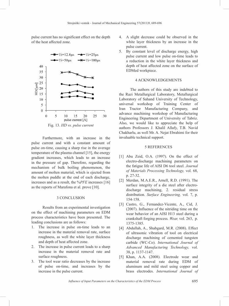
From Figs. 12 and 13 it is clear that increasing the pulse current has a very small effect on the white layer thickness and the depth of the heat affected zone. Although an increase in pulse current leads to an increase in the dimensions of the molten crater and the heat penetrating depth, the plasma flushing efficiency increases as pulse current increases. The increase in plasma flushing efficiency causes more molten material to be swept away from the molten crater, therefore, a thinner layer of re-deposited material appears on the surface of the workpiece. Since an increase in the penetrating depth of heat into the workpiece and plasma flushing efficiency counterbalance the effect they have on each other, an increase in the
Fig. 10. WT vs. pulse on-time
Fig. 11. HD vs. pulse on-time
Fig. 12. WT vs. pulse current
Strojniški vestnik - Journal of Mechanical Engineering 57(2011)9, 689-696
695Influence of Input Parameters on the Characteristics of the EDM Process
pulse current has no significant effect on the depth of the heat affected zone.
Fig. 13. HD vs. pulse current
Furthermore, with an increase in the pulse current and with a constant amount of pulse on-time, causing a sharp rise in the average temperature of the plasma channel [15], the energy gradient increases, which leads to an increase in the pressure of gap. Therefore, regarding the mechanism of bulk boiling phenomenon, the amount of molten material, which is ejected from the molten puddle at the end of each discharge, increases and as a result, the %PFE increases [16] as the reports of Marafona et al. prove [10].
3 CONCLUSION
Results from an experimental investigation on the effect of machining parameters on EDM process characteristics have been presented. The leading conclusions are as follows:1. The increase in pulse on-time leads to an
increase in the material removal rate, surface roughness, as well the white layer thickness and depth of heat affected zone.
2. The increase in pulse current leads to a sharp increase in the material removal rate and surface roughness.
3. The tool wear ratio decreases by the increase of pulse on-time, and increases by the increase in the pulse current.
4. A slight decrease could be observed in the white layer thickness by an increase in the pulse current.
5. By constant level of discharge energy, high pulse current and low pulse on-time leads to a reduction in the white layer thickness and depth of heat affected zone on the surface of EDMed workpiece.
4 ACKNOWLEDGEMENTS
The authors of this study are indebted to the Razi Metallurgical Laboratory, Metallurgical Laboratory of Sahand University of Technology, universal workshop of Training Center of Iran Tractor Manufacturing Company, and advance machining workshop of Manufacturing Engineering Department of University of Tabriz. Also, we would like to appreciate the help of authors Professors J. Khalil Allafy, T.B. Navid Chakharlu, as well Mr. A. Nejat Ebrahimi for their invaluable technical support.
5 REFERENCES
[1] Abu Zeid, O.A. (1997). On the effect of electro-discharge machining parameters on the fatigue life of AISI D6 tool steel. Journal of Materials Processing Technology, vol. 68, p. 27-32.
[2] Merdan, M.A.E.R., Arnell, R.D. (1991). The surface integrity of a die steel after electro-discharge machining, 2. residual stress distribution. Surface Engineering, vol. 7, p. 154-158.
[3] Castro, G., Fernandez-Vicente, A., Cid, J. (2007). Influence of the nitriding time on the wear behavior of an AISI H13 steel during a crankshaft forging process. Wear, vol. 263, p. 1375-1385.
[4] Abdullah, A., Shabgard, M.R. (2008). Effect of ultrasonic vibration of tool on electrical discharge machining of cemented tungsten carbide (WC-Co). International Journal of Advanced Manufacturing Technology, vol. 38, p. 1137-1147.
[5] Khan, A.A. (2008). Electrode wear and material removal rate during EDM of aluminum and mild steel using copper and brass electrodes. International Journal of

Strojniški vestnik - Journal of Mechanical Engineering 57(2011)9, 689-696
696 Shabgard, M. – Seyedzavvar, M. – Oliaei, S.N.B.
Advanced Manufacturing Technology, vol. 39, p. 482-487.
[6] Dibitoto, D.D., Eubank, Ph.T., Patel, M.R., Barrufet, M.A. (1989). Theoretical models of the electrical discharge machining process, I. A simple cathode erosion model. Journal of Applied Physics, vol. 66, no. 9, p. 4095-4103.
[7] Mamalis, A.G., Vosniakos, G.C., Vaxevanidis, N.M. (1987). Macroscopic phenomena of electro-discharge machined steel surface: an experimental investigation. Journal of Mechanical Working Technology, vol. 15, p. 335-356.
[8] Boujelbene, M., Bayraktar, E., Tebni, W., Ben Salem, S. (2009). Influence of machining parameters on the surface integrity in electrical discharge machining. Archive of Materials Science and Engineering, vol. 37, p. 110-116.
[9] Rebelo, J.C., Dias Morao, A., Kremer, D., Lebrun, J.L. (1998). Influence of EDM pulse energy on the surface integrity of martensitic steel. Journal of Materials Processing Technology, vol. 84, p. 90-96.
[10] Böhler Edelstahl, http://www.bohler-edelstahl.at, accesed on 2008-08-23.
[11] Fischer, U., Heinzle, M., Näher, F., Paetzold, H., Gomeringer, R., Kilgus, R., Oesterle, S., Stephan, A. (2008). Tabellenbuch Metall.
Verlag Europa-Lehrmittel, Nourney, Vollmer GmbH & Co. KG, Haan-Gruiten.
[12] Lee, H.T. Tai, T.Y. (2003). Relationship between EDM parameters and surface crack formation. Journal of Materials Processing Technology, vol. 142, p. 676-683.
[13] Hascalyk, A., Caydas, U. (2004). Experimental study of wire electrical discharge machining of AISI D5 tool steel. Journal of Materials Processing Technology, vol. 148, p. 362-367.
[14] Petropoulos, G.P., Vaxevanidis, N.M., Radovanoviü, M., Zoler, C. (2009). Morphological - Functional Aspects of Electro-Discharge Machined Surface Textures. Strojniški vestnik - Journal of Mechanical Engineering, vol. 55, no. 2, p. 95-103.
[15] Kansal, H.K., Singh, S., Kumar, P. (2008). Numerical simulation of powder mixed electric discharge machining (PMEDM) using finite element method. Mathematical and Computer Modeling. vol. 47, p. 1217-1237.
[16] Das, S., Klotz, M., Klocke, F. (2003). EDM simulation: finite element-based calculation of deformation, microstructure and residual stresses. Journal of Materials Processing Technology, vol. 142, p. 434-451.