Inertial stabilization of buckling at high rates of loading and low test ...
12
Inertial stabilization of buckling at high rates of loading and low test temperatures: Implications for dynamic crush resistance of aluminum-alloy-based sandwich plates with lattice core Xin Tang a , Vikas Prakash a, * , John J. Lewandowski b , Gregory W. Kooistra c , Haydn N.G. Wadley c a Department of Mechanical and Aerospace Engineering, Case School of Engineering, Case Western Reserve University, Cleveland, OH 44106-7222, USA b Department of Materials Science and Engineering, Case School of Engineering, Case Western Reserve University, Cleveland, OH 44106-7222, USA c Department of Materials Science and Engineering, University of Virginia, Charlottesville, VA 22904, USA Received 26 September 2006; received in revised form 4 November 2006; accepted 11 December 2006 Available online 6 March 2007 Abstract In the present study, the dynamic compressive behavior of aluminum-alloy-based tetrahedral-core truss structures is investigated as a function of impact velocity using a split Hopkinson pressure bar. The results are used to understand the phenomenon of buckling in truss structures as a function of loading rates and test temperatures, and its implication on the dynamic crush resistance of tetrahedral-truss- based sandwich structures. In order to understand the effects of the flow strength of the core on the dynamic crush resistance, truss struc- tures of both T6 and OA heat-treatments of AA6061 were investigated. A high-speed digital camera was used to record the sequence of the deformation and failure events that occur during the dynamic compression and failure of the truss sub-elements. A buckling insta- bility was observed to occur consistently for both the T6 and OA microstructures at all test temperatures employed in the present study. Moreover, the T6 heat-treatment and the lower-than-room test temperatures significantly increase the specific energy absorption capa- bilities of the truss structures. Ó 2007 Acta Materialia Inc. Published by Elsevier Ltd. All rights reserved. Keywords: Aluminum-alloy 6061; Tetrahedral core truss structure; Inertial stabilization of buckling; Dynamic crush resistance; Low test temperatures 1. Introduction The response of monolithic beams and plates to impact loading has been extensively investigated in the past. For example, Seiler and Symonds [15] and Wang and Hopkins [23] have analyzed the impulsive response of beams and clamped circular plates, respectively. More recently, advances in material fabrication and processing have led to the emergence of a new class of ultra-lightweight, high-energy-absorption cellular material systems. Exam- ples of such systems include metal foams and truss core lat- tice structures. In particular, Wadley et al. introduced a new fabrication methodology to fabricate metal-based open-cell tetrahedral truss core structures from aluminum alloy sheets [16,22,9]. These cores are made by folding stretched hexagonally perforated Al-6061 sheets. Simple air-brazing is then used to construct sandwich panels with cellular cores with relative densities between 0.02 and 0.08. Research on periodic cellular materials has been widely reported in the context of minimum weight design, advances in manufacturing, mechanical characterization, structural integrity and large-scale simulations. Amongst these efforts, experimental studies providing a fundamental understanding of the mechanical behavior of these materi- als have been of particular importance. Quasi-static tests have been accurately reconciled with models of metal- based foams that account for ligament bending. Those 1359-6454/$30.00 Ó 2007 Acta Materialia Inc. Published by Elsevier Ltd. All rights reserved. doi:10.1016/j.actamat.2006.12.037 * Corresponding author. Tel.: +1 216 368 6440; fax: +1 216 368 3007. E-mail address: [email protected] (V. Prakash). www.actamat-journals.com Acta Materialia 55 (2007) 2829–2840
Transcript of Inertial stabilization of buckling at high rates of loading and low test ...

www.actamat-journals.com
Acta Materialia 55 (2007) 2829–2840
Inertial stabilization of buckling at high rates of loading and lowtest temperatures: Implications for dynamic crush resistanceof aluminum-alloy-based sandwich plates with lattice core
Xin Tang a, Vikas Prakash a,*, John J. Lewandowski b, Gregory W. Kooistra c,Haydn N.G. Wadley c
a Department of Mechanical and Aerospace Engineering, Case School of Engineering, Case Western Reserve University, Cleveland, OH 44106-7222, USAb Department of Materials Science and Engineering, Case School of Engineering, Case Western Reserve University, Cleveland, OH 44106-7222, USA
c Department of Materials Science and Engineering, University of Virginia, Charlottesville, VA 22904, USA
Received 26 September 2006; received in revised form 4 November 2006; accepted 11 December 2006Available online 6 March 2007
Abstract
In the present study, the dynamic compressive behavior of aluminum-alloy-based tetrahedral-core truss structures is investigated as afunction of impact velocity using a split Hopkinson pressure bar. The results are used to understand the phenomenon of buckling in trussstructures as a function of loading rates and test temperatures, and its implication on the dynamic crush resistance of tetrahedral-truss-based sandwich structures. In order to understand the effects of the flow strength of the core on the dynamic crush resistance, truss struc-tures of both T6 and OA heat-treatments of AA6061 were investigated. A high-speed digital camera was used to record the sequence ofthe deformation and failure events that occur during the dynamic compression and failure of the truss sub-elements. A buckling insta-bility was observed to occur consistently for both the T6 and OA microstructures at all test temperatures employed in the present study.Moreover, the T6 heat-treatment and the lower-than-room test temperatures significantly increase the specific energy absorption capa-bilities of the truss structures.� 2007 Acta Materialia Inc. Published by Elsevier Ltd. All rights reserved.
Keywords: Aluminum-alloy 6061; Tetrahedral core truss structure; Inertial stabilization of buckling; Dynamic crush resistance; Low test temperatures
1. Introduction
The response of monolithic beams and plates to impactloading has been extensively investigated in the past. Forexample, Seiler and Symonds [15] and Wang and Hopkins[23] have analyzed the impulsive response of beams andclamped circular plates, respectively. More recently,advances in material fabrication and processing have ledto the emergence of a new class of ultra-lightweight,high-energy-absorption cellular material systems. Exam-ples of such systems include metal foams and truss core lat-tice structures. In particular, Wadley et al. introduced a
1359-6454/$30.00 � 2007 Acta Materialia Inc. Published by Elsevier Ltd. All
doi:10.1016/j.actamat.2006.12.037
* Corresponding author. Tel.: +1 216 368 6440; fax: +1 216 368 3007.E-mail address: [email protected] (V. Prakash).
new fabrication methodology to fabricate metal-basedopen-cell tetrahedral truss core structures from aluminumalloy sheets [16,22,9]. These cores are made by foldingstretched hexagonally perforated Al-6061 sheets. Simpleair-brazing is then used to construct sandwich panels withcellular cores with relative densities between 0.02 and 0.08.
Research on periodic cellular materials has been widelyreported in the context of minimum weight design,advances in manufacturing, mechanical characterization,structural integrity and large-scale simulations. Amongstthese efforts, experimental studies providing a fundamentalunderstanding of the mechanical behavior of these materi-als have been of particular importance. Quasi-static testshave been accurately reconciled with models of metal-based foams that account for ligament bending. Those
rights reserved.

2830 X. Tang et al. / Acta Materialia 55 (2007) 2829–2840
for periodic truss-element cellular cores have addressedplastic yielding and inelastic truss buckling. However, itis now understood that the dynamic response of thesematerials is significantly different from that measuredunder quasi-static conditions. Besides material strain ratesensitivity [14,6,2,3,27,17,28], two other dynamic effects[21,26] are understood to significantly affect the core behav-ior: (i) inertial resistance of the core to the motion of thefront face-sheet and the consequent plastic-wave propaga-tion in the core; and (ii) inertial stabilization of the core lig-aments that can delay the onset of buckling, therebymaintaining the effective strength of the core to much lar-ger crushing strains than under quasi-static crushing. Coreligament stabilization is also understood to lead to signifi-cant increase in the energy-absorption capacity of the lat-tice core sandwich plates.
In some of the earlier studies on cellular materials, Bart-Smith et al. [1] reported both the measured and simulatedbending performance of sandwich panels with thin cellularmetal cores (an Alporas core and two Al alloy face sheets).Using collapse load criteria for face yielding, core shearand indentation, they developed a mechanism map thatcharacterized the observed predominant failure phenom-ena. Xue and Hutchinson [25] compared the performanceof metal sandwich plates and solid plates made from thesame material and mass under impulsive blast loads. Intheir study, three core geometries were evaluated: pyrami-dal truss, square honeycomb and the folded plate. Theyreported that sandwich plates made from these three coregeometries can sustain a much larger blast loading whencompared to a solid plate of equal mass; the square honey-comb and folded plate cores were consistently observed tooutperform the truss cores. They also proposed the possi-bility of using structural optimization schemes that couldpossibly lead to even greater improvements in the perfor-mance of the sandwich plates. Wicks and Hutchinson [24]examined the mechanical performance of sandwich plateswith truss cores. They found the truss core constructionto be as efficient as the honeycomb cores at carrying theprescribed combinations of moment and transverse forceswhen a realistic minimum crushing strength was imposed.Truss cores were found to possess an inherent crushingadvantage at the low core densities typical of most sand-wich plate designs. For the case of woven textile cores,Lee et al. [10] presented the compressive behavior of 304stainless steel woven textile core materials obtained overa wide regime of deformation rates. A well-defined failuremode transition was observed when the deformation ratewas increased from 500 s�1 to 1 · 104 s�1, and the peakstress was found to be deformation rate sensitive. At lowstrain-rates, the collapse zone was observed to be in thecentral region, with shear bands at ±45� in orientation,while at the high strain-rates the collapse occurred adjacentto the impact surface and propagated through the specimenin the direction of impact. The overall dynamic response ofthe textile cores was classified to be in between the open-cell foams and the pyramidal truss core cellular materials.
Following these early ideas, Qiu et al. [11,12] conductedextensive research involving structural optimization anddeveloped analytic approximations for the behavior ofsandwich panels subjected to blast loading. Valdevit et al.[20] evaluated the optimal dimensions and the minimumweight of sandwich panels with prismatic cores. Theyreported that the corrugated core sandwich panels per-formed best when loaded longitudinally, and attributedthis to their greater buckling resistance; the diamond pris-matic core panels (with corrugation order = 4) were foundto be slightly more weight efficient when compared to thetruss, when optimized for a specific loading direction.Rathbun et al. [13], using a shock simulation techniqueinvolving high-speed impact of Al-foam projectile, studiedand compared the performance of stainless steel squarehoneycomb core sandwich and solid monolithic beams sub-jected to high-pressure, short-duration impulses. Thesestudies confirmed that sandwich beams with square honey-comb cores demonstrated considerably smaller displace-ments when compared to the solid steel beams of equalmass when subjected to impulse/shock loading. In particu-lar, for low-amplitude impulses, i.e. when the core has suf-ficient dynamic strength to prevent appreciable crushing,the benefits of the sandwich structure were particularlylarge. Hutchinson and Xue [7] analyzed square honeycombcore plates for the best achievable performance and foroptimal mass distribution between the face plates and thecores. The model was also used to discuss a number ofissues related to the design of effective metal sandwichplates, including differing requirements for air and waterenvironments, face-sheet shear-off resistance, the role ofcore strength and the relation between small-scale testsand full-scale behavior.
From these studies it is now understood that all-metalsandwich plates have distinct advantages over monolithicplates of equal mass for structures designed to withstandintense short-duration pressure pulses, especially in waterenvironments. To be effective under intense impulsiveloads, a sandwich plate must be able to dissipate, via corecrushing, a significant fraction of the kinetic energy initiallyacquired. Consequently, if a plate is to retain its integritywith only limited crushing, its core must have ample crush-ing strength and high energy-absorbing capacity. Thehigher core strength is expected to limit core crushing,enable high specific energy absorption, and maintain bend-ing strength of the plate; sandwich plates with weaker coresrequire a much higher fraction of their mass in their core.
The objective of the present paper is to better under-stand inertial stabilization of buckling as a function ofloading rates and the material yield strength and its rolein controlling the crush resistance of aluminum-alloy-basedsandwich structures (Fig. 1). Both T6 and over-aged (OA)of AA6061, which are known to have very different yieldand flow strengths under dynamic compression [18], wereutilized. Moreover, the test temperatures were varied fromroom to lower-than-room temperature (down to �170 �C).The focus of our study was the tetrahedral truss core

Fig. 1. Schematic of the manufacturing process of the tetrahedral latticetruss cores involving perforation and folding.
X. Tang et al. / Acta Materialia 55 (2007) 2829–2840 2831
because it has been shown to have a relatively high specificcrushing strength and energy absorption capacity that isessential if the sandwich plate is to outperform the solidplate construction. In order to conduct the dynamic exper-iments, the AA6061 alloy truss sub-elements, in the twoheat-treatments, were dynamically deformed in compres-sion using the split Hopkinson pressure bar (SHPB) facilityin the Department of Mechanical and Aerospace Engineer-ing at Case Western Reserve University. Moreover, a mod-ified SHPB facility, which incorporates a low-temperaturechamber, was used to conduct the lower-than-room testtemperature experiments. The results of these experimentswere used to examine the effects of the changes in yieldstrength and flow behavior of the lattice core material oninertial stabilization of the truss ligaments, and hence thespecific energy absorption and crush resistance of the tetra-hedral core sub-elements.
2. Experimental procedure
2.1. Materials
In the present study, the AA6061 alloy sandwich panelswere acquired as 4 in. square plates from the University of
Fig. 2. (a) Photographs of the perforated sheet used to form a 4.8% relativefolding operation.
Virginia. Age-hardenable Al–Mg–Si aluminum alloy (6061)tetrahedral lattice truss sandwich panels were made using arecently developed sheet folding process [16]. The latticeswere brazed to solid face sheets of similar alloy composi-tion and tested in both the annealed and peak age-hard-ened conditions. Details of the fabrication of thetetrahedral lattice sandwich panels are provided next.
2.1.1. Tetrahedral lattice truss and sandwich panel
fabrication
A folding process was used to bend elongated hexagonalperforated AA6061 (Al–0.6Si–1.0Mg–0.28Cu–0.20Cr wt.%) sheet to create a single layer 50% occupancytetrahedral truss lattice [9]. Fig. 1 schematically shows theprocess. The folding was accomplished node row by noderow using a paired punch and die tool with the sheetsfolded so as to form regular tetrahedrons (i.e. the angleh = 54.7�).
An example of an elongated hexagonal perforated sheet(with open area fraction of 0.82) that would create a tetra-hedral lattice with predicted relative density, �q ¼ 0:067 isshown in Fig. 2a. Fig. 2b shows a folded tetrahedral latticetruss with a (measured) pre braze relative density,�q ¼ 0:048. The relative density of the truss cores was variedby using different perforated sheet thicknesses and appro-priately spacing the perforating punches to maintain asquare truss cross section. This required only one punch/die set to produce the five relative density latticesinvestigated.
Sandwich panels were constructed from the folded trussstructures by placing a tetrahedral lattice core betweenAA6951 alloy sheets clad with AA4343 braze alloy. Alloycompositions, melting and brazing temperatures are shownin Table 1. The assembly was then coated with a proprie-tary metal-halide flux slurry (Handy Flo-X5518, LucasMilhaupt Inc., Cudahy, WI), dried and placed in a mufflefurnace for brazing. Each assembly was heated to between595 ± 5 �C for approximately 5–10 ± 1 min (depending onsandwich mass) to minimize the joint weakening associatedwith silicon interdiffusion from the brazing alloy. After
density core and (b) the corresponding tetrahedral lattice truss after the
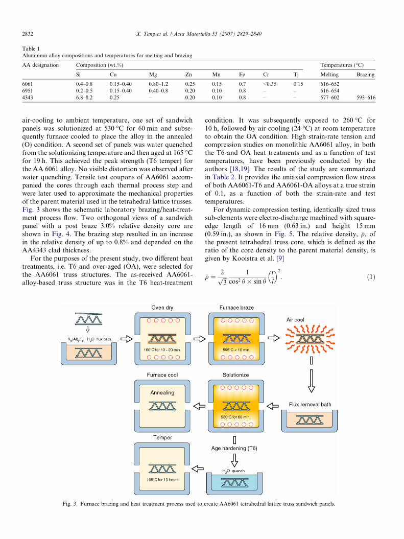
Table 1Aluminum alloy compositions and temperatures for melting and brazing
AA designation Composition (wt.%) Temperatures (�C)
Si Cu Mg Zn Mn Fe Cr Ti Melting Brazing
6061 0.4–0.8 0.15–0.40 0.80–1.2 0.25 0.15 0.7 <0.35 0.15 616–6526951 0.2–0.5 0.15–0.40 0.40–0.8 0.20 0.10 0.8 – – 616–6544343 6.8–8.2 0.25 – 0.20 0.10 0.8 – – 577–602 593–616
2832 X. Tang et al. / Acta Materialia 55 (2007) 2829–2840
air-cooling to ambient temperature, one set of sandwichpanels was solutionized at 530 �C for 60 min and subse-quently furnace cooled to place the alloy in the annealed(O) condition. A second set of panels was water quenchedfrom the solutionizing temperature and then aged at 165 �Cfor 19 h. This achieved the peak strength (T6 temper) forthe AA 6061 alloy. No visible distortion was observed afterwater quenching. Tensile test coupons of AA6061 accom-panied the cores through each thermal process step andwere later used to approximate the mechanical propertiesof the parent material used in the tetrahedral lattice trusses.Fig. 3 shows the schematic laboratory brazing/heat-treat-ment process flow. Two orthogonal views of a sandwichpanel with a post braze 3.0% relative density core areshown in Fig. 4. The brazing step resulted in an increasein the relative density of up to 0.8% and depended on theAA4343 clad thickness.
For the purposes of the present study, two different heattreatments, i.e. T6 and over-aged (OA), were selected forthe AA6061 truss structures. The as-received AA6061-alloy-based truss structure was in the T6 heat-treatment
Fig. 3. Furnace brazing and heat treatment process used to
condition. It was subsequently exposed to 260 �C for10 h, followed by air cooling (24 �C) at room temperatureto obtain the OA condition. High strain-rate tension andcompression studies on monolithic AA6061 alloy, in boththe T6 and OA heat treatments and as a function of testtemperatures, have been previously conducted by theauthors [18,19]. The results of the study are summarizedin Table 2. It provides the uniaxial compression flow stressof both AA6061-T6 and AA6061-OA alloys at a true strainof 0.1, as a function of both the strain-rate and testtemperatures.
For dynamic compression testing, identically sized trusssub-elements were electro-discharge machined with square-edge length of 16 mm (0.63 in.) and height 15 mm(0.59 in.), as shown in Fig. 5. The relative density, �q, ofthe present tetrahedral truss core, which is defined as theratio of the core density to the parent material density, isgiven by Kooistra et al. [9]
�q ¼ 2ffiffiffi3p 1
cos2 h� sin htl
� �2
: ð1Þ
create AA6061 tetrahedral lattice truss sandwich panels.

Fig. 4. Views of the 3.0% relative density brazed tetrahedral lattice.
X. Tang et al. / Acta Materialia 55 (2007) 2829–2840 2833
In Eq. (1) h is the angle between each tetrahedral strut andthe corresponding base tetrahedron, and t and l are the tet-rahedral strut thickness and length, respectively. Consider-ing the topology properties of a regular tetrahedron,h ¼ arctanð
ffiffiffi2pÞ ¼ 54:7�. For the sample used in present
study, t and l are 1.5 mm (0.059 in.) and 13.4 mm(0.53 in.), respectively. Thus, the relative density, �q, forthe truss core used in the present investigation is 0.0524.
Table 2The uniaxial compression flow stress of AA6061-T6 and AA6061-OAalloys at a true strain of 0.1 and at different strain-rates and testtemperatures [18,19]
Materials Test temp. (�C) Strain-rate(_e, s�1)
Flow stress(at etrue = 0.1, MPa)
AA6061-T6 24 1 · 10�2 3251.536 · 103 4253.267 · 103 4454.660 · 103 4854.889 · 103 4605.814 · 103 440
�170 7.966 · 103 4355.293 · 103 535
AA6061-OA 24 1 · 10�2 1951.555 · 103 2752.122 · 103 2703.254 · 103 2654.142 · 103 2755.298 · 103 2809.136 · 103 295
�170 6.817 · 103 380
2.2. Dynamic compression testing: the split Hopkinson
pressure bar (SHPB)
The high-strain-rate dynamic compression experimentson the aluminum-alloy-based tetrahedral sub-elements(shown in Fig. 5) were conducted using the SHPB facilityin the Department of Mechanical and Aerospace Engineer-ing at Case Western Reserve University. The schematic ofthe SHPB facility is shown in Fig. 6. The SHPB comprisesa striker bar, an incident bar and a transmitter bar, allmade from high-strength maraging steel with nominal yieldstrength of 2.2 GPa. The striker bar used in the experi-ments was approximately 0.6 m long, while the incidentand transmitter bars were 1.524 m in length. The diameterof all the pressure bars was 19.05 mm (0.75 in.). A pair ofsemiconductor strain gages (BLH SPB3-18-100-U1) werestrategically attached on the incident and transmitter bars;
Fig. 5. Photographs of the aluminum alloy-based open-cell tetrahedralcore truss structure sub-element used in the present study.

Fig. 6. Schematic of the split Hopkinson pressure bar (SHPB) at CWRU.
2834 X. Tang et al. / Acta Materialia 55 (2007) 2829–2840
these gages were used in the combination with a Wheat-stone bridge circuit, connected to a differential amplifier(Tektronix 5A22N) and a digital oscilloscope (TektronixTDS 420) to record the strain-gage profiles in the incidentand the transmitter bars during the test.
In order to conduct the experiments, the truss sub-ele-ment specimen was placed between the incident and trans-mitter bars, as shown schematically in Fig. 7. In allexperiments, the contacting surfaces of the sub-elementwere polished with ultra-fine sandpaper (up to 2400 grit).Moreover, molybdenum-disulfide grease was used betweenthe sub-element surfaces and the incident and transmitterbars to minimize friction.
An IMACON 200 high-speed digital camera, with amaximum framing rate of 200 million frames per second,was used to monitor the dynamic deformation process.The camera allows a maximum of 16 frames of a typicalshort-duration event to be recorded. The framing rate isadjustable so as to allow for the best coverage of the entireevent. For simple visual imagery, the high-speed camerauses a Photogenic Power Light 2500 DR flash, whichilluminates the test sample (sub-element) with �1 kJ oflight energy within a span of about 200 ls. The camera isconfigured with appropriate Nikon lenses for the bestmagnification and visibility, and is placed at an optimumdistance from the test sample for the requiredmagnification.
In order to conduct the experiments on the truss sub-ele-ments, the striker bar is accelerated by means of a com-pressed-air gas-gun to impact the incident bar; the impact
Fig. 7. Expanded view of incident bar/sub-element/transmitter bar region.
results in an elastic compression wave, with a strain profileei(t), traveling along the incident bar towards the sub-ele-ment sample. Because of the impedance mismatch betweenthe sub-element and the pressure bars, part of the wave,er(t), is reflected back into the incident bar, and the rest,et(t), is transmitted through the sub-element specimen intothe transmitter bar. Based on the one-dimensional elasticwave-propagation and SHPB theory [4,5] the engineeringstress r(t), engineering strain-rate _eðtÞ, and the engineeringstrain e(t) in the sub-element can be calculated:
rðtÞ ¼ EA0
AsetðtÞ; ð2Þ
_eðtÞ ¼ �2c0
LserðtÞ; ð3Þ
eðtÞ ¼Z t
0
_eðtÞ dt: ð4Þ
In Eqs. (2)–(4), E, A0 and c0 are the Young’s modulus,cross-sectional area and longitudinal wave speed of thepressure bars, and As and Ls are the initial contact cross-sectional area and height of the sub-element tested.
Due to the anisotropic topology of the truss structure,the true-stress vs. true-strain profile in the sub-element isdifficult to estimate, since in the analysis of the traditionalSHPB tests on isotropic and homogeneous specimens, iso-choric and uniform deformation conditions are assumed toprevail within the specimen [4,5]. Instead, a force vs. dis-placement curve for the truss sub-element sample is esti-mated by multiplying the nominal engineering stress withthe original sub-element contact area, while the displace-ment of the sub-element during dynamic compressionwas calculated by multiplying the nominal engineeringstrain by the original specimen height.
To conduct the low-temperature SHPB tests, a simplelightweight plastic foam cooling tank, shown in Fig. 8,was designed to keep the specimen immersed in liquidnitrogen (at �196 �C) prior to the dynamic compressiontesting. To accommodate the incident and the transmitterbars within the cooling tank, two holes, with diametersclose to those of the incident and transmitter pressure bars,

Fig. 8. Schematic of the split Hopkinson pressure bar (SHPB) coupled with the cooling foam tank at CWRU.
X. Tang et al. / Acta Materialia 55 (2007) 2829–2840 2835
were drilled on the opposite curved surfaces of the tank.Prior to impact, the sub-element sample was clamped atthe ends of the incident and transmitter bars within thefoam cooling tank. Liquid nitrogen was then poured intothe cooling tank to fully immerse the specimen as well asthe ends of the pressure bars. The temperature of thesub-element was monitored by a 0.015 in. chromel–alumelthermal couple wire attached to the sub-element.
3. Experimental results and discussion
Table 3 provides a summary of all the experiments con-ducted in the present study. It provides the test number, theheat-treatment of the aluminum alloy used for the trusssub-element, the projectile bar velocity and the test temper-ature. In order to compare the dynamic deformation char-acteristics of the truss sub-elements at the room and�170 �C test temperatures, the impact velocity of the stri-ker bar was controlled to be approximately 20 m s�1. Thiscorresponds to an input stress level of �400 MPa. For allexperiments the length of the striker bar was fixed at0.6 m (�24 in.). This corresponds to a input pulse durationof �250 ls. For Test 4 an impact velocity of 11.3 m s�1 wasused. The motivation using the lower impact velocity wasto deform the truss sub-element to an intermediate stage,such that it is pushed into the post-buckled regime butnot completely crushed. Post-test examination of the trusscore was then used to elucidate the modes and sequence of
Table 3List of all experiments performed to study the crush resistance of AA6061-T6
Test no. AA6061 Heattreatment
Impact velocity of striker bar(m s�1)
Ampl(MPa
1 Al-6061-T6 22.7 4442 Al-6061-T6 22.6 4403 Al-6061-T6 22.8 4454 Al-6061-T6 11.3 2205 Al-6061-T6 23.3 4556 Al-6061-OA 19.5 3807 Al-6061-OA 23.6 460
events that lead of failure, e.g. initiation of plastic bucklinginstability, role of micro-inertia, etc., in the truss elementsprior to complete collapse.
The force vs. displacement profiles obtained duringdynamic crushing of the AA6061-T6 and AA6061-OAsub-elements at both room and lower-than-room test tem-peratures are shown in Fig. 9. The oscillations in the force–displacement curves are understood to be a consequence ofstress wave dispersion in the truss sub-element and also dueto the complex load transfer path changes during collapseof the truss core structure during dynamic compression.The average strain-rate, estimated from the transmitterbar gage signals, was �1000 s�1. However, for Test 4, thenominal strain rate was �500 s�1. This is because a lowerimpact velocity was used in this experiment. In both theroom temperature and lower-than-room test temperaturetests, the AA6061-T6 sub-elements exhibited higher com-pressive strength and consistently absorbed higher impactenergy when compared to the AA6061-OA alloy structures.This behavior is consistent with the dynamic yield strengthand flow-stress reported for the two alloys on monolithiccylindrical compression specimens [18,19], as discussed inTable 3.
In addition to obtaining the force–displacement curves,in some of the room temperature tests the IMACON 200high-speed camera was utilized to observe the deformationand failure process of the truss sub-elements. Analysis car-ried out by Xue and Hutchinson [26] and Vaughn et al. [21]
/AA6061-OA truss structures at room and lower-than-room temperatures
itude of input pulse)
Duration of input pulse(ls)
Test temperature(�C)
258 24260 24260 24238 �170218 �170221 24219 �170

Displacement (mm)
For
ce (k
N)
0 0.5 1 1.5 2 2.5 30
0.5
1
1.5
2
2.5
3
3.5
4
4.5
5
Al-6061-T6:Test 1 (RoomTemp)Al-6061-T6:Test 3 (RoomTemp)Al-6061-T6:Test 4 (-170oC)Al-6061-T6:Test 5 (-170oC)Al-6061-OA: Test 6 (24oC)Al-6061-OA:Test 7 (-170oC)
SHPB Tests on Al-6061-T6 and Al-6061-OALattice Core Structures
Fig. 9. SHPB results on the AA6061-T6 and AA6061-OA truss sub-elements at both room and lower-than-room test temperatures.
2836 X. Tang et al. / Acta Materialia 55 (2007) 2829–2840
have shown that strong dynamic effects come into playwhen sandwich plates are subject to high-intensity stresspulses. They introduced an important dimensionlessparameter governing the inertial effects, Vo/(coeY), whereVo is the relative velocity of the sandwich faces,co ¼
ffiffiffiffiffiffiffiffiffiE=q
pis the elastic wave speed in the truss core mate-
rial, and E, q and eY are the Young’s modulus, density andthe initial yield strain of the metal ligaments, respectively.To gain an appreciation of the timescales involved in theexperiments discussed here, consider the AA6061-T6 trusssub-element with a core thickness of h = 15 mm, whosefront face is abruptly accelerated to a velocity of
Fig. 10. The initiation of plastic instability in Al-6061-T6 truss sub-element durtemperature (frames are selected from the high-speed camera photography). Bthe plastic instability.
Vo = 20 m s�1. For this case, Vo/(coeY) � 4 (assumingeY = 0.001) and the overall strain rate is_e ¼ V o=H ¼ 1333=s. In this range the material strain-ratedependence is understood to be important. The otherdynamic effects that are also expected to play an importantrole include the inertial resistance of the core to the motionof the front face-sheet and the consequent plastic wavepropagation in the truss core, and the inertial stabilizationof the truss core that delays the onset of the truss buckling,thereby maintaining the effective strength of the core tomuch larger crushing strains than observed under quasi-static crushing.
Fig. 10 shows a sequence of selected frames taken from atypical dynamic compression test for an AA6061-T6 trusssub-element. The exposure time for each frame is 30 ns,while the inter-frame time is 5 ls. The images in Fig. 10represent every two frames taken from the photographysequence; thus the time interval between photos is 10 ls.For typical elastic and plastic wave speeds, co = 5000 m/sand cp = 500 m/s, and the elastic and plastic wave frontsare expected to reach the back face at times t = 3 ls and30 ls, respectively. Fig. 11a shows the voltage vs. time sig-nal showing the incident pulse, the reflected pulse and thetransmitted pulse signals obtained in Test 1. Fig. 11b showsthe corresponding force vs. time and the strain vs. time sig-nals obtained from the measured incident and the transmit-ter bar strain profiles using Eqs. (2)–(4). Superimposed onthe figure are selected frames from the high-speed video ofthe dynamic crush event. The amplitude of the force in theinput stress pulse is 126 kN with a rise time of approxi-mately 50 ls. The maximum crush force in the truss sub-element is 2.2 kN, and is reached at �70 ls after the stresspulse loading.Thereafter the force carried by the truss sub-
ing a typical dynamic compression test conducted using the SHPB at roomold arrows indicate loading direction while thin arrows locate initiation of

Time (μs)
Inci
dent
Bar
Sig
nal (
Volt)
Tran
smitt
er B
ar S
igna
l (Vo
lt)
-400 -300 -200 -100 0 100 200 300-2
-1.5
-1
-0.5
0
0.5
1
1.5
2
-0.1
-0.05
0
0.05
0.1
Incident Signal
Reflected Signal
Transmitted Signal
Test 1: Al-6061-T6 Truss sub-elementRoomTemperature
Time (μs)
Forc
e (k
N)
Engi
neer
ing
Stra
in
0 50 100 150 200 250 300 3500
0.5
1
1.5
2
2.5
3
3.5
4
4.5
5
0
0.05
0.1
0.15
0.2
0.25
0.3
SHPB test of Al-6061-T6 Truss Core Sub-elementTest 1(RoomTemperature)Average Strainrate1072 s-1
Frame 8
Frame 191 μs
171 μs
131 μs
151 μs
Frame 16
Frame 12
a
b
Fig. 11. (a) Strain gage voltage vs. time profile showing the incident bar signal, the reflected bar signal and the transmitter bar signal on the truss sub-element at room temperature in Test 1. Note: the incident and reflected bar signals and the transmitter bar signal do not have the same scale. (b) Thecorresponding force–time curve measured during the dynamic compressive test on the Al-6061-T6 alloy at room test temperature (average nominal strain-rate 1072 s�1).
X. Tang et al. / Acta Materialia 55 (2007) 2829–2840 2837
element is observed to decrease. This decrease in force isunderstood to be due to the initiation of elastic/plasticbuckling in the ligaments as the stress builds up in the trusssub-element. As mentioned before, the time taken for theplastic wave to propagate to the back surface of the trusssub-element is �30 ls after the arrival of the incident stresspulse. However, the first evidence of the initiation of plasticinstability occurs in frame 4 (at 111 ls); the progression ofdamage/buckling can be observed after frame 6 (141 ls).This provides direct evidence of the beneficial effects ofmicro-inertia in delaying the initiation of plastic instabilitywithin the ligaments of the truss sub-elements. As thedynamic compression proceeds, the instability spreads to
the other ligaments and eventually the entire core as thesub-element is fully crushed.
Fig. 12 shows the post-test pictures of the Al-6061 alloytruss sub-elements. In all the high-velocity impact experi-ments (impact velocity �20 m s�1), the truss sub-elementstructures are observed to completely crush during thedynamic deformation process. However, for the case ofthe 10 m s�1 impact velocity, the truss sub-element isobserved to undergo only plastic buckling, and is recoveredprior to complete crushing of the truss core. At the roomtemperature, the peak compressive forces in AA6061-T6sub-elements ranged from approximately 2.2 kN to2.5 kN, while those in AA6061-OA sub-elements were

Fig. 12. Post-test examination of the AA6061-T6 and AA6061-OA trusssub-elements at room and lower-than-room temperatures. (a) The originalAA6061-T6 truss sub-element sample. (b) The buckled AA6061-T6 trusssub-element from Test 4. (c) The completely crushed AA6061-T6 trusssub-element.
2838 X. Tang et al. / Acta Materialia 55 (2007) 2829–2840
approximately 1.4 kN. At the lower-than-room test tem-peratures (�170 �C), the peak compressive forces in theAA6061-T6 sub-elements were in the range of 3.0–3.3 kN, while for the AA6061-OA sub-elements the peakforces were �2.1 kN. Also, for the room temperature tests,the specific energy absorption ranged from 16 to 21 J kg�1
for the AA6061-T6 sub-elements, while for the AA6061-
Table 4Average nominal strain-rate, maximum crush force, and the specific energy astructures at both room and lower-than-room test temperatures
Testno.
AA6061 heattreatment
Impact velocity of striker bar(m s AA6061)
Testtemperature(�C)
1 Al-6061-T6 22.7 242 Al-6061-T6 22.6 243 Al-6061-T6 22.8 244 Al-6061-T6 11.3 �1705 Al-6061-T6 23.3 �1706 Al-6061-OA 19.5 247 Al-6061-OA 23.6 �170
OA sub-elements the absorption was �11 J kg�1. At thelower-than-room test temperatures (�170 �C), the specificenergy absorption in the AA6061-T6 sub-elements wasapproximately 28 J kg�1, and that of AA6061-OA sub-ele-ments was approximately 21 J kg�1. Thus, the levels ofcrush resistance and impact energy absorption are muchhigher for the case of the T6 alloys (higher strength trusscore materials), and at lower-than-room test temperatures.Table 4 summarizes the main results of the tests: it providesthe average nominal strain-rate achieved in the tests, themaximum compressive force sustained by the truss core(maximum crush force), and the specific energy absorptionobtained from all the dynamic compression tests conductedin the present study at both the room and lower-than-roomtest temperatures.
The dynamic force vs. displacement curves, for both theT6 and the OA heat-treatments (presented in Fig. 9), arehigher by a factor of 2 when compared to those obtainedunder quasi-static deformation conditions (�6.7 ·10�2 s�1). The beneficial effects on energy absorption areunderstood to be due to the elevated strain rates and thelow test temperatures that result in an elevation of the forcevs. displacement curve during testing. This must occur dueto changes in the deformation and flow behavior of thesealuminum alloys when tested at low temperature and highstrain rates, as summarized in Tang [19], and discussedbelow. Perhaps more importantly, this elevation of theforce vs. displacement curve is a result of the micro-inertiain the truss ligaments that results in a delay in the bucklinginstability, as shown in Fig. 10, thereby increasing thecrush resistance.
The beneficial effects of testing various aluminum alloysat low test temperatures and/or high strain rates have occa-sionally been reported for Charpy impact testing as well asfracture toughness testing of a variety of commercial alu-minum alloys [8]. Tabular summaries of various aluminumalloys have also indicated measurable increases in thequasi-static yield strength, UTS and notch tensile strengthon reducing the test temperature from room temperature to�320 �F, with further increases on going down to �452 �F.Recent results [18,19] clearly show that increasing thestrain-rate as well as decreasing the test temperatureincreased the yield and UTS, without significantly degrad-ing the reduction in area for 6061 in both the T6 and OA
bsorption capability obtained in the dynamic tests on AA6061 truss core
Average strain-rate (s�1)
Max crush force(kN)
Specific energy absorption(N m kg�1)
1072 2.2 20.81060 2.4 15.61071 2.3 18.3520 3.0 16.1
1039 3.3 27.9904 1.4 11.2
1125 2.1 20.9

X. Tang et al. / Acta Materialia 55 (2007) 2829–2840 2839
conditions. Furthermore, in situ high-speed video that wasintegrated with the high-rate uniaxial test results haveenabled a comparison of calculated necking instabilitystrains to those revealed via the high-speed video underthese different test conditions. The results clearly showedan elevation of the tensile necking strains with an increasein strain-rate and decrease in test temperature. This effectwas maximized at the highest strain rates and lowest testtemperatures. The source of the increased necking strainwas shown to be due to the increased work-hardening rateexhibited by the samples tested under these conditions. Theincreased work-hardening rate counteracts the geometricsoftening experienced during tensile deformation, therebyprolonging the uniform strain regime. The increased yieldstress, UTS and work-hardening rates obtained under theseconditions indicate that the energy-absorbing ability of thematerial under tensile or compressive conditions shouldincrease with respect to that obtained at room temperature.This has been documented in other published summaries[19], although the source(s) of these improvements werenot discussed.
The present tests on the AA6061-T6 and AA6061-OAtruss sub-elements, where the buckling instability is inhib-ited at low temperatures and high strain-rates therebyincreasing the crush resistance, are broadly consistent withthese other recent observations made on the effects of highstrain-rate and low temperature on the energy absorbedduring tensile or compression testing of monolithicAA6061-T6 and AA6061-OA. The increased yield strength,UTS and work-hardening rate exhibited by the monolithicAA6061-T6 and AA6061-OA obtained at high strain-ratesand low test temperatures are consistent with the elevatedload vs. displacement curves obtained during high-rate/low-temperature testing of the truss sub-elements (Fig. 9).The delay of the buckling instability in the truss sub-ele-ment ligaments that accompanies these rate and tempera-ture induced changes in properties thereby increases thecrush resistance and energy-absorbing characteristics ofsuch structures constructed of these monolithic aluminumalloys. Additional work is needed on structures constructedfrom other aluminum alloys and heat treatments in orderto determine if the presently reported results are broadlyrepresentative of the behavior of other aluminum alloystructures.
4. Conclusions
In the present study, the dynamic compressive behaviorof AA6061-based open-cell tetrahedral core truss struc-tures under two different heat treatment conditions, T6and OA, has been investigated under uniaxial dynamiccompression loading over a range of test temperaturesfrom room temperature down to �170 �C. At all loadingrates, truss structures constructed of AA6061-T6 exhibita higher crush resistance and greater energy-absorbingcapability than those constructed of AA6061-OA, whichis in good consistency with the previous studies on the
dynamic compressive properties of monolithic AA6061-T6 and AA6061-OA materials. In addition, lower test tem-peratures were found to produce significant effects on theforce–displacement curves of the truss structures. Reducedtest temperatures increase the crush resistance and mechan-ical energy absorption capability of the truss structurestested in the present study. These results have importantimplications in the design and performance of blast-resis-tant lightweight truss structures, and indicate that at lowerthan room temperatures and at elevated strain-rates, thetruss structure made from these alloys have a potential tosustain higher deformations and absorb more impactenergy prior to complete failure. The dynamic compressivedeformation process of the truss structure was also cap-tured by a high-speed camera.
Acknowledgments
The authors acknowledge the Case Western ReserveUniversity (Case Prime Fellowship) and the Office of NavalResearch (ONR-N00014-03-1-0351) for financial support.The authors also acknowledge the Major Research Instru-mentation award, CMS 0079458, by the National ScienceFoundation for the acquisition of the ultra-high-speed dig-ital camera used in the present experiments. Critical read-ing and comments by Prof. J.W. Hutchinson, HarvardUniversity, are particularly appreciated.
References
[1] Bart-Smith H, Hutchinson JW, Evans AG. Measurement andanalysis of the structural performance of cellular metal sandwichconstruction. Int J Mech Sci 2001;43(8):1945–63.
[2] Dannemann KA, Lankford J. High strain rate compression ofclosed-cell aluminium foams. Mater Sci Eng A 2000;293(1–2):157–64.
[3] Deshpande VS, Fleck NA. High strain rate compressive behaviour ofaluminium alloy foams. Int J Impact Eng 2000;24(3):277–98.
[4] Follansbee PS. The Hopkinson bar. Mechanical testing, metalshandbook, vol. 8. Metals Park (OH): ASM International; 1985. p.198–217.
[5] Gray GT. Classic split-Hopkinson bar testing. Mechanical testing andevaluation handbook, vol. 8. Materials Park (OH): American Soci-ety for Metals; 2000. p. 462–476.
[6] Harrigan JJ, Reid SR, Peng C. Inertia effects in impact energyabsorbing materials and structures. Int J Impact Eng 1999;22(9–10):955–79.
[7] Hutchinson JW, Xue ZY. Metal sandwich plates optimized forpressure impulses. Int J Mech Sci 2005;47(4–5):545–69.
[8] Kaufman JG. Fracture resistance of aluminum alloys-notch tough-ness, tear resistance, and fracture toughness. Materials Park(OH): The Aluminum Association, ASM International; 2001.
[9] Kooistra GW, Deshpande VS, Wadley HNG. Compressive behaviorof age hardenable tetrahedral lattice truss structures made fromaluminium. Acta Mater 2004;52(14):4229–37.
[10] Lee S, Barthelat F, Moldovan N, Espinosa HD, Wadley HNG.Deformation rate effects on failure modes of open-cell Al foams andtextile cellular materials. Int J Solids Struct 2006;43(1):53–73.
[11] Qiu X, Deshpande VS, Fleck NA. Dynamic response of a clampedcircular sandwich plate subject to shock loading. J Appl Mech –Trans ASME 2004;71(5):637–45.

2840 X. Tang et al. / Acta Materialia 55 (2007) 2829–2840
[12] Qiu X, Deshpande VS, Fleck NA. Impulsive loading of clampedmonolithic and sandwich beams over a central patch. J Mech PhysSolids 2005;53(5):1015–46.
[13] Rathbun HJ, Radford DD, Xue Z, He MY, Yang J, Deshpande V,et al. Performance of metallic honeycomb-core sandwich beamsunder shock loading. Int J Solids Struct 2006;43(6):1746–63.
[14] Reid SR, Peng C. Dynamic uniaxial crushing of wood. Int J ImpactEng 1997;19(5–6):531–70.
[15] Seiler JA, Symonds PS. Plastic deformation in beams under distrib-uted dynamic loads. J Appl Phys 1954;25(5):56–563.
[16] Sypeck DJ, Wadley HNG. Cellular metal truss core sandwichstructures. Adv Eng Mater 2002;4(10):759–64.
[17] Tan PJ, Harrigan JJ, Reid SR. Inertia effects in uniaxial dynamiccompression of a closed cell aluminium alloy foam. Mater SciTechnol 2002;18(5):480–8.
[18] Tang X, Prakash V, Lewandowski JJ. Dynamic deformation ofaluminum 6061 alloys in two different heat-treatments (Paper #323,s.7). Proceedings of the 2005 SEM annual conference and expositionon experimental and applied mechanics. Bethel (CT): Society ofExperimental Mechanics Inc; 2005.
[19] Tang X. Dynamic deformation of aluminum 6061 alloys in twodifferent heat-treatments. MS thesis, Case Western Reserve Univer-sity, Cleveland (OH); 2006.
[20] Valdevit L, Hutchinson JW, Evans AG. Structurally optimized sand-wich panels with prismatic cores. Int J Solids Struct 2004;41(18–19):5105–24.
[21] Vaughn D, Canning M, Hutchinson JW. Coupled plastic wavepropagation and column buckling. J Appl Mech 2005;72:1–8.
[22] Wadley NG. Cellular metals manufacturing. Adv Eng Mater2002;4(10):726–33.
[23] Wang AJ, Hopkins HG. On the plastic deformation of built-incircular plates under impulsive load. J Mech Phys Solids 1954;3:22–37.
[24] Wicks N, Hutchinson JW. Performance of sandwich plates with trusscores. Mech Mater 2004;36(8):739–51.
[25] Xue ZY, Hutchinson JW. A comparative study of impulse-resistant metal sandwich plates. Int J Impact Eng 2004;30(10):1283–305.
[26] Xue ZY, Hutchinson JW. Crush dynamics of square honeycombsandwich cores. Int J Numer Methods Eng 2006;65(13):2221–45.
[27] Yi F, Zhu ZG, Hu SS, Yi P, He LH, Ning T. Dynamic compressivebehavior of aluminum alloy foams. J Mater Sci Lett 2001;20(18):1667–8.
[28] Yu JL, Wang X, Wei ZG, Wang EH. Deformation and failuremechanism of dynamically loaded sandwich beams with aluminum-foam core. Int J Impact Eng 2003;28(3):331–47.