Local tourism governance - USQ ePrints - University of Southern
University of Southern Queensland
Faculty of Engineering and Surveying
Induced Draft (ID) Fan Lubrication System
Design Review and Proposed Modification
Upgrade at Callide C Power Station
A dissertation submitted by
Stuart Baker
in the fulfilment of the requirements of
Courses ENG4111/4112 Research Project
towards the degree of
Bachelor of Engineering (Mechanical)
28 October, 2010

i
Abstract
Australia’s coal fired power stations are the most efficient form of providing
bulk base load power generation (i.e. electricity) to consumers. This is due
to Australia having an abundance of thermal coal reserves, which is the fuel
used in coal fired power stations. Therefore it is extremely important that
these power stations operate at maximum availability and reliability to ensure
the consumer receives cost effective and uninterrupted electricity.
Callide C Power Station in Biloela Queensland is a 900 Megawatt (MW) coal
fired power station that was commissioned in 2001. Unfortunately Callide C
Power Station has been plagued with continuous operational and reliability
problems caused from the induced draft (ID) fans since initial commissioning.
The ID fan problems have arisen from the bearing lubrication system which
provides oil recirculation to the induction motor bearings and fan main shaft
bearings. Consequently these issues have caused half-load unit (225 MW)
run-backs and full unit (450 MW) trips over the past decade.
This project’s aim is to analyse the ID fan lubrication system and then
identify and define all root causes and their associated failure modes. Once
all root causes are identified through Root Cause Analysis (RCA) process,
effective design solutions can be researched and evaluated so a proposed
modification design project can be finalised. This final design proposal will
be used to justify capital expenditure so implementation can occur in the
near future.
ii
University of Southern Queensland
Faculty of Engineering and Surveying
Limitations of Use
The Council of the University of Southern Queensland, its Faculty of Engineering and Surveying, and the staff of the University of Southern Queensland, do not accept any responsibility for the truth, accuracy or completeness of material contained within or associated with this dissertation. Persons using all or any part of this material do so at their own risk, and not at the risk of the Council of the University of Southern Queensland, its Faculty of Engineering and Surveying or the staff of the University of Southern Queensland. This dissertation reports an educational exercise and has no purpose or validity beyond this exercise. The sole purpose of the course pair entitled "Research Project" is to contribute to the overall education within the student’s chosen degree program. This document, the associated hardware, software, drawings, and other material set out in the associated appendices should not be used for any other purpose: if they are so used, it is entirely at the risk of the user.
Prof Frank Bullen Dean Faculty of Engineering
ENG4111 & ENG4112 Research Project
iii
Certification
I certify that the ideas, designs and experimental work, results, analyses and conclusions set out in this dissertation are entirely my own effort, except where otherwise indicated and acknowledged. I further certify that the work is original and has not been previously submitted for assessment in any other course or institution, except where specifically stated. Stuart D. Baker Student Number: 0050068776
__________________________________
Signature __________________________________
Date

iv
Acknowledgements
This project was conducted under the principle supervision of Mr Bob Fulcher, Faculty of Engineering and Surveying, University of Southern Queensland. I would also like to acknowledge and thank the technical engineering staff and Callide C maintenance staff at Callide Power Station for their continuous support, mentoring and assistance.
Stuart D. Baker
v
Glossary
AC: Alternating Current
AS: Australian Standards
ASME: American Society of Mechanical Engineers
CNC: Computer Numerical Control
CO2: Carbon Dioxide
cSt: Centistokes
DC: Direct Current
DE: Drive end
DN: Nominal Diameter
DNB: Departure from nucleate boiling
EP: Extreme Pressure
FD: Forced Draft
HHI: Hyundai Heavy Industries
HV: High Voltage
ICMS: Integrated Control Management System
ID: Induced Draft
IHI: Ishikawajima – Harima Heavy Industries
kg/s: Kilogram per second
kPa: Kilopascal = 1000 Pascals
kV: Kilovolt = 1000 volts
kW: Kilowatt = 1000 watts
L/min: Litre per minute
vi
m: metre
M: Metric
ml: Millilitre
mm: Millimetre
mm2/s: Millimetre squared per second
m/s: Metre per second
m3/s: Metre cubed per second
MPa: Megapascal = 1000000 Pascals
MRC: Maximum Continuous Rating
MW: Megawatt = 1000000 watts
MWh: Megawatt hour = 1000000 watts for one hour
NDE: Non-drive end
OEM: Original Equipment Manufacturer
PA: Primary Air
P&ID: Piping and Instrumentation Diagram
PF: Pulveriser Fuel
RCA: Root Cause Analysis
rpm: Revolution per minute
V: Volt
VI: Viscosity Index
µm: Micrometre (micron) = 1 x 10⁻⁶ m
vii
Symbology
A Cross-sectional area [m2]
D Pipe inside diameter [mm]
1D Orifice inside diameter (DE) [mm]
2D Orifice inside diameter (NDE) [mm]
f Friction factor
F Voltage frequency [Hz]
g Gravitational acceleration [m/s2]
h Potential head [m]
1h Major head loss [m]
mh1 Minor head loss [m]
H Total head loss [m]
K Loss coefficient factor
L Length of pipe [m]
n Revolutions per minute [rpm]
p Pressure [kPa]
P Number of motor winding poles
Q Volumetric flow rate [L/min]
Re Reynolds number
Srpm Synchronous revolutions per minute [Srpm]
v Kinematic viscosity [m3/s]
viii
V Displacement per revolution [cm3/rev]
V& Fluid flow rate [m3/s]
V Fluid velocity [m/s]
η Volumetric efficiency [%]
ix
Table of Contents
Abstract i
Limitations of Use ii
Certification iii
Acknowledgements iv
Glossary v
Symbology vii
Table of Contents ix
List of Figures xii
List of Tables xiv
List of Appendices xv
Chapter 1 – Introduction 1
1.1 Project Objectives...........................................................................1
1.2 Background ....................................................................................2
1.3 Reliability Issues with Callide C Power Station...............................4
1.3.1 ID Fan Lubrication System Reliability Issues...........................6
1.3.2 Pressure Monitoring versus Flow Monitoring...........................8
Chapter 2 – Literature Review 10
2.1 General operation of Callide C Power Station ..............................10
2.2 Characteristics of Supercritical Boilers .........................................11
2.2.1 Supercritical versus Subcritical..............................................11
x
2.3 Callide C Boiler Draft System .......................................................15
2.4 Boiler Draft Efficiency and Design ................................................17
2.4.1 Fan Margins ..........................................................................17
2.4.2 Fan Types .............................................................................18
2.5 Tribology of Rotating Machines ....................................................21
2.5.1 Bearing Design......................................................................21
2.5.2 Callide C ID Fan and Electric Motor Bearings .......................27
2.5.3 Lubrication Theory.................................................................27
2.5.4 Fluid Film Lubrication ............................................................29
2.5.5 Callide C ID Fan Lubrication..................................................29
Chapter 3 – Methodology 31
3.1 Further Research and Appraisal...................................................31
3.1.1 Bearing Selection ..................................................................31
3.1.2 Lubrication Selection .............................................................35
3.2 Root Cause Analysis Methodology...............................................38
3.2.1 Pump Internal Wear...............................................................40
3.2.2 Airlock in Stand-by Pump ......................................................45
3.3.3 Complex System Design .......................................................48
3.3.4 Flow Transmitters Removed..................................................51
3.3.5 Incorrect Pressure Trip Values ..............................................53
Chapter 4 – Effective Design Solutions 55
4.1 Research and Evaluation of Solutions..........................................55
4.1.1 Particle Contamination ..........................................................55
4.1.2 Internal Tank Design .............................................................57
xi
4.1.3 Simplify System Design.........................................................60
4.1.4 Suitable Flow Transmitters ....................................................61
4.1.5 Pressure Alarm and Trip Values............................................69
Chapter 5 – Modification Design Proposal 70
5.1 Design Considerations..................................................................70
5.1.1 Filter Element Selection.........................................................70
5.1.2 Internal Tank Modifications....................................................70
5.1.3 Fixed-size Orifices .................................................................72
5.1.4 Accurate Flow Transmitters...................................................75
5.1.5 Modified Pressure Alarm and Trip Values .............................78
5.2 Modification Design Overview ......................................................82
Chapter 6 – Conclusion 83
6.1 Project Outcomes .........................................................................83
6.2 Further Work.................................................................................84
References 85
xii
List of Figures
Figure 1.1: Callide C ID fan and induction motor ...........................................5
Figure 1.2: Lubrication system P&ID..............................................................6
Figure 2.1: Boiler circulations methods ........................................................12
Figure 2.2: Furnace tube size and temperature comparison........................13
Figure 2.3: Subcritical versus supercritical steam........................................14
Figure 2.4: Callide C – Balanced draft PF boiler ..........................................16
Figure 2.5: Typical draft-loss pressure diagram for a PF Boiler ...................16
Figure 2.6: Centrifugal fan flow path ............................................................18
Figure 2.7: Axial fan flow path......................................................................19
Figure 2.8: Efficiency comparison of various fan types ................................20
Figure 2.9: Typical ball bearing cross sections ............................................23
Figure 2.10: Hydrodynamic journal bearing cross section ...........................25
Figure 2.11: Hydrostatic journal bearing cross section ................................25
Figure 3.1: Induction motor bearing selection graph ....................................33
Figure 3.2: Causal Tree Analysis .................................................................39
Figure 3.3: Exploded assembly drawing of gear pump ................................41
Figure 3.4: Abrasion wear on gear pump outer casing ................................44
Figure 3.5: Abrasion wear on gear pump shaft bearing ...............................44
Figure 3.6: Lubrication pump P&ID..............................................................45
Figure 3.7: Individual pump pressure test ....................................................46
Figure 3.8: Lubrication pump P&ID with local test pressure gauge..............47
Figure 3.9: ID fan lubrication tank internal arrangement ..............................48
xiii
Figure 3.10: Lubrication system P&ID..........................................................49
Figure 3.11: Two throttle valves located inside cabinet................................50
Figure 3.12: Adjustable orifice......................................................................50
Figure 3.13: OEM Hedland flow transmitter .................................................51
Figure 4.1: Variable area measurement principle ........................................63
Figure 4.2: A typical Yokogawa variable area flow transmitter.....................64
Figure 4.3: Operation principle of an oval gear flowmeter............................65
Figure 4.4: A typical Macnaught positive displacement flow transmitter ......66
Figure 4.5: Coriolis mass operating principle ...............................................67
Figure 4.6: A typical Yokogawa coriolis mass transmitter ............................68
Figure 5.1: Proposed de-aeration screen design .........................................71
Figure 5.2: Fixed-size orifice 3D model........................................................74
Figure 5.3: Fixed-size orifice Matlab script...................................................74
Figure 5.4: Modified lubrication system P&ID ..............................................77
xiv
List of Tables
Table 2.1 – Shell Tellus S 46 oil properties..................................................30
Table 3.1 – Comparison of gear pump specifications ..................................41
Table 3.2 – Comparison of oil particle contamination ..................................43
Table 3.3 – Comparison of flow transmitter specification.............................52
Table 3.4 – Comparison of flow rate and pressure protection values ..........53
Table 4.1: Comparison of cleanliness code .................................................56
Table 4.2 – Advantages and disadvantages of variable area flowmeters ....63
Table 4.3 – Advantages and disadvantages of positive displacement
flowmeters....................................................................................................65
Table 4.4 – Advantages and disadvantages of coriolis mass flowmeters ....68
Table 5.1 – Comparison of Macnaught flow transmitter specifications ........76
Table 5.2 – OEM flow rate protection values ...............................................76
Table 5.3 – Alarm and trip conditions for head loss calculations .................78
Table 5.4 – Fan main shaft bearing protection values .................................80
Table 5.5 – Induction motor bearing protection values ................................81
Table 5.6 – Comparison of pressure protection values................................82

xv
List of Appendices
Appendix A – Project Specification..........................................................87
Appendix B – Engineering Design Drawings ..........................................88
Appendix C – Flow Meter Specifications .................................................90
Appendix D – Matlab Programs................................................................94

1
Chapter 1 – Introduction
1.1 Project Objectives
The aim of this project is to conduct an engineering appraisal on the
operational and reliability issues in the existing Callide C Power Station
induced draft (ID) fan lubrication system, and recommend a cost effective
and reliable design for a future modification project. Project objectives are:
1. To describe the general operation of Callide C Power Station with
special attention to boiler section pertaining to induced draft (ID) fan
operations.
2. Research theory on lubrication and bearing systems in rotating
equipment.
3. Investigate further information on the different types of bearings and
lubrication used in heavy electric drives and axial fans.
4. Identify the operational and reliability failure modes in the existing ID fan
lubrication system which is causing protection alarms and trips.
5. Research and evaluate effective design solutions to prevent reoccurring
operational and reliability issues in the existing ID fan lubrication system.
6. Prepare a modification design recommendation that will make certain
the lubrication system is designed for correct functionality and long-term
reliability.
7. Submit an academic dissertation on the engineering research
conducted and proposed design modification to the ID fan lubrication
system.

2
1.2 Background
The rapid technological advances in todays electrical hardware and
software has lead to our civilization becoming increasing dependant on
electrical power, also commonly known as electricity. This increasing
dependence on electricity is forcing power generation companies all
throughout Australia to produce reliable, cost effective and safe electricity
for their consumers. Electricity in Australia is commonly produced in large
scale using a four types of electrical power generation methods, these
include:
• Coal fired power stations
• Gas fired power stations
• Hydro driven power stations
• Large wind turbine farms
Of the four types listed above, coal fired power stations are the most
favoured in Australia as they are the most efficient method of bulk base
load power generation. Australia is also very fortunate to have an
abundance of thermal coal reserves, which is the fuel used in coal fired
power stations. In Australia, base load coal fired power generation units
range in size from 30 megawatt (MW) units which were built in 1960’s all
the way to 750 MW units built in recent years.
Bulk base load power generation is paramount in sustaining a stable
electrical network (i.e. grid) system as it ensures continuous uninterrupted
supply of electricity to the consumer. This stability is built from base load
power stations which are designed to run at constant operating output, all
day and every day with the exception of planned outages.

3
A major disadvantage when building electrical network systems on large
base load units ranging from 350 MW to 750 MW is when a power
generation unit unexpectedly trips offline to the grid, it leaves a big gap in
the transmission supply which can lead to voltage and frequency instability.
Such events can cause forced network load shedding, where electricity
load is tripped from the grid.
An example of this, take Queensland’s 2009 peak electricity consumption of
8699 MW (Department of Mines and Energy 2010) and Kogan Creek
Power Station in Chinchilla Queensland, a single 750 MW base load unit.
When 750 MW is tripped offline from the state grid of 8699 MW,
approximately 9% of available supply electricity is lost and this gap must be
instantaneously supplied from other power stations connected to the grid. If
such an event occurs simultaneous with multiple power stations tripping
offline, the entire grid can become unstable which can lead to regional and
state blackouts. To avoid grid instability and power blackouts it is crucial
that power stations are designed, maintained and operated to run at
maximum availability and reliability.
However, all power generation stations from time to time suffer from
reliability issues mainly caused from inadequate design factors, lack of
maintenance procedures and skills, and operator error. To combat such
factors that cause reliability issues in large base load power stations. It is
generally the responsibility of the technical engineering staff to adopt a
continuous improvement culture which investigates and analyses key
performance and reliability issues. Such investigations, better known as
Root Cause Analysis (RCA) are very popular in today’s industry as this
process identifies root causes in machinery failure and poor reliability.
Once the root causes are identified and understood, the technical
engineering department is able to proceed with modification concepts and
designs to prevent reoccurrence of the problem causing poor reliability.

4
1.3 Reliability Issues with Callide C Power Station
Callide C Power Station is situated 18 kilometres east from the township of
Biloela, approximately 120 kilometres west of Gladstone Queensland.
Callide C Power Station is quite famous as it was the first supercritical coal-
fired power station built and commissioned in Australia, in the year 2001
(Power Technology 2010). Callide C has a total generation capacity of 900
MW which consist of 2 x IHI supercritical power generation units capable of
450 MW per unit. This amount of continuous generation is the basis for
Callide C being an integral base load power generation station in
Queensland’s state electricity grid.
Each of the two 450 MW units consists of two Howden Variax Dual Stage
Axial Flow Induced Draft (ID) Fans. Each fan is powered via an alternating
current (AC) 6600 volt - 3 phase 6 pole synchronous induction motor
manufactured by Hyundai Heavy Industries (HHI). The four ID fans have
suffered from reliability and operational issues from commissioning stage in
2001, which has caused half load unit run-backs and full load unit trips. A
half load 225 MW unit run-back occurs when one ID fan trips and a full unit
450 MW trip occurs when both ID fans trip. This amount of generation
capacity tripping off the grid unexpectedly has the potential to cause
frequency and voltage instability of the state grid at peak times.

5
Figure 1.1: Callide C ID fan and induction motor
The ID fan problems have arisen from the bearing lubrication system which
supplies oil recirculation to the induction motor bearings at 15 – 16 L/min
and fan main shaft bearings at 15 - 18 L/min. The lubrication system has 2
x 100% duty cycle lubrication pumps, so one pump is always in standby.
Prior to 2004, there were two flow transmitters on each lubrication line
(refer to Figure 1.2) that were used to provide alarm and trip values for
equipment protection. These values were used by the Integrated Control
Management System (ICMS) for the following parameters:
• Low oil flow alarm
• Oil flow for fan start condition
• Low oil flow fan trip
• Low oil flow start stand-by lubrication pump
6
Figure 1.2: Lubrication system P&ID
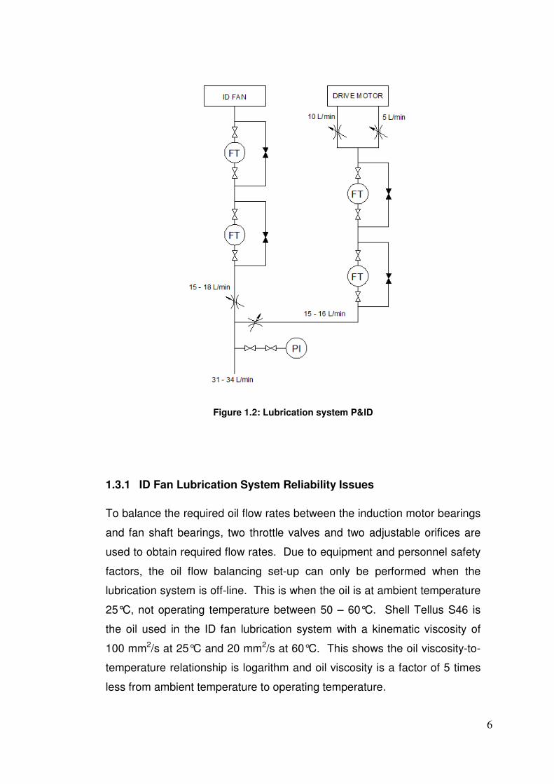
1.3.1 ID Fan Lubrication System Reliability Issues
To balance the required oil flow rates between the induction motor bearings
and fan shaft bearings, two throttle valves and two adjustable orifices are
used to obtain required flow rates. Due to equipment and personnel safety
factors, the oil flow balancing set-up can only be performed when the
lubrication system is off-line. This is when the oil is at ambient temperature
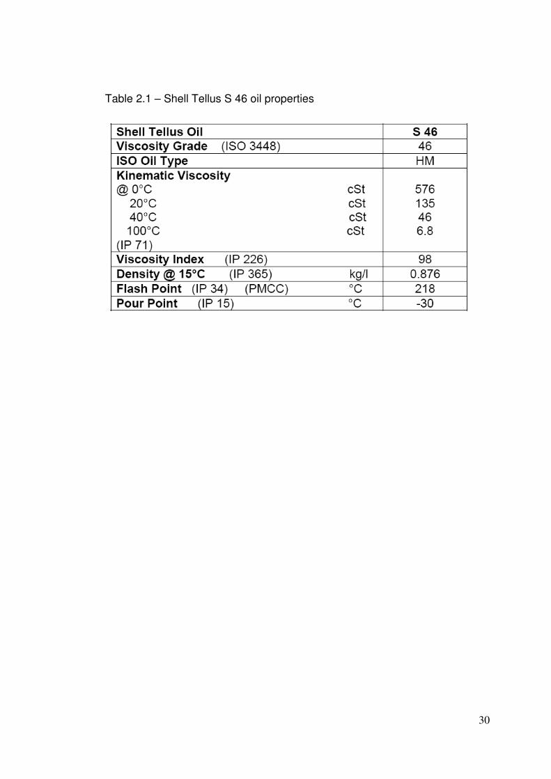
25°C, not operating temperature between 50 – 60°C. Shell Tellus S46 is
the oil used in the ID fan lubrication system with a kinematic viscosity of
100 mm2/s at 25°C and 20 mm2/s at 60°C. This shows the oil viscosity-to-
temperature relationship is logarithm and oil viscosity is a factor of 5 times
less from ambient temperature to operating temperature.
7
The problems became apparent after the oil flow balancing set-up was
completed and the ID fan returned to service and eventually oil temperature
reached 60°C and even higher on hot summer days. The oil viscosity and
density would decrease causing the flow transmitters to read a lower value
then previous for oil flow rate. This would then create a low oil flow alarm in
the ICMS and then start the stand-by pump in an attempt to increase oil
flow rate to above alarm value. However, due to poor design factors the
stand-by pump was unable to self-prime and make system pressure.
Therefore no additional oil flow was created and eventually the ID fan would
trip on low oil flow.
To combat this issue, the operation and maintenance teams would
eventually get the stand-by pump to prime and return the ID fan back to
service with the both lubrication pumps running simultaneously. Having two
pumps running ensured oil flow rate was much greater than alarm and trip
values, therefore preventing future alarms and trips. However this solution
created another problem, if a lubrication pump dropped performance or
completely failed, the oil flow rate would again drop to alarm and trip value,
eventually tripping the ID fan.
The flow transmitters also suffered from other failure modes such as: (1) oil
leaking internally into the electrical circuitry causing loss of analog output
signal to the ICMS, (2) could not be site calibrated to suit different fluid
viscosity and density, and (3) contamination of small particles in the oil
caused sticking of the internal components. To rectify this problem, in 2004
an engineering modification was implemented which replaced the four flow
transmitters with four pressure transmitters in an attempt to reduce the
number of ID fan alarms and trips. The alarm and trip pressure protection
values were supplied from the fan supplier, Howden Australia.

8
This modification unfortunately suffered from the same fate as the flow
transmitters. As the oil viscosity and density decreased when oil reached
operating temperature, the flow resistance also decreased and therefore
reducing line pressure to both the induction motor bearings and fan main
shaft bearings. This drop in line pressure would again create low oil
pressure alarms and trips, eventually tripping the ID fan. So unfortunately
this engineering modification did not prove successful and did not eliminate
the root causes.
Some work was recently done to decrease the pressure alarm and trip
values which did prevent oil pressure alarms and trips. However this
solution still did not address the issue of the stand-by pump not making
system pressure when started. This aspect is very important as operations
are required to change-over lubrication pump from duty cycle to stand-by
cycle every month to prove pump performance and integrity. So every
month when this operational activity occurs, the stand-by pump can not
make system pressure which leads to a critical machine operating with no
stand-by lubrication pump.
1.3.2 Pressure Monitoring versus Flow Monitoring
Pressure is not the desired online monitoring parameter for the ID fan
lubrication system as the ‘Original Equipment Manufacturer’ (OEM) plant
manual gives oil flow rates for operation conditions, not oil pressures. The
reason for oil flow rate as the preferred monitoring parameter is because
the induction motor bearings and fan main shaft bearings are oil bath
configuration. Therefore oil flow to the bearing inlet is only slightly above
atmospheric pressure and the only ‘head’ resistance created is from
dynamic friction of pipes, fittings and orifices. This means pressure will
dramatically vary with oil temperature however flow rate will always remain
constant.
9
It must also be further emphasised when pressure is increased, the
corresponding flow does not necessary increase. If the cross-sectional
area of an oil line is decreased upstream of the pressure transmitter by
reducing orifice size, then line pressure will increase due to an increase in
‘head’ resistance. However, oil flow rate will not increase, instead oil flow
rate can actually decrease causing possible bearing overheating and failure.
The actual decrease in oil flow rate is dependant on system design, pump
type and pump performance.
10
Chapter 2 – Literature Review
2.1 General operation of Callide C Power Station
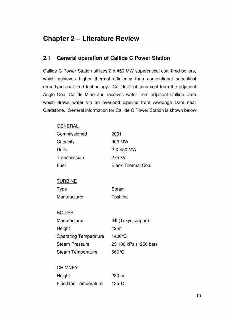
Callide C Power Station utilises 2 x 450 MW supercritical coal-fired boilers,
which achieves higher thermal efficiency than conventional subcritical
drum-type coal-fired technology. Callide C obtains coal from the adjacent
Anglo Coal Callide Mine and receives water from adjacent Callide Dam
which draws water via an overland pipeline from Awoonga Dam near
Gladstone. General information for Callide C Power Station is shown below:
GENERAL
Commissioned 2001
Capacity 900 MW
Units 2 X 450 MW
Transmission 275 kV
Fuel Black Thermal Coal
TURBINE
Type Steam
Manufacturer Toshiba
BOILER
Manufacturer IHI (Tokyo, Japan)
Height 42 m
Operating Temperature 1400°C
Steam Pressure 25 100 kPa (~250 bar)
Steam Temperature 566°C
CHIMNEY
Height 230 m
Flue Gas Temperature 135°C
11
2.2 Characteristics of Supercritical Boilers
Supercritical boiler technology was introduced to the power industry in the
early 1960’s. Since this time, there have been many innovative boiler
design configurations and features introduced to reduce capital and
operating costs, simplify operation and maintenance, and increase reliability.
2.2.1 Supercritical versus Subcritical
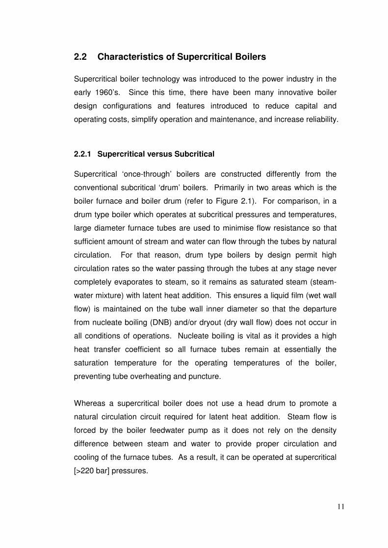
Supercritical ‘once-through’ boilers are constructed differently from the
conventional subcritical ‘drum’ boilers. Primarily in two areas which is the
boiler furnace and boiler drum (refer to Figure 2.1). For comparison, in a
drum type boiler which operates at subcritical pressures and temperatures,
large diameter furnace tubes are used to minimise flow resistance so that
sufficient amount of stream and water can flow through the tubes by natural
circulation. For that reason, drum type boilers by design permit high
circulation rates so the water passing through the tubes at any stage never
completely evaporates to steam, so it remains as saturated steam (steam-
water mixture) with latent heat addition. This ensures a liquid film (wet wall
flow) is maintained on the tube wall inner diameter so that the departure
from nucleate boiling (DNB) and/or dryout (dry wall flow) does not occur in
all conditions of operations. Nucleate boiling is vital as it provides a high
heat transfer coefficient so all furnace tubes remain at essentially the
saturation temperature for the operating temperatures of the boiler,
preventing tube overheating and puncture.
Whereas a supercritical boiler does not use a head drum to promote a
natural circulation circuit required for latent heat addition. Steam flow is
forced by the boiler feedwater pump as it does not rely on the density
difference between steam and water to provide proper circulation and
cooling of the furnace tubes. As a result, it can be operated at supercritical
[>220 bar] pressures.
12
Figure 2.1: Boiler circulations methods
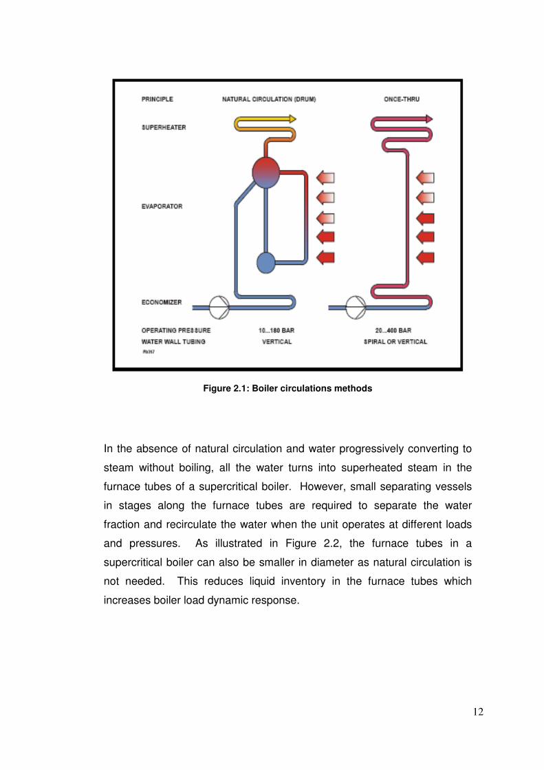
In the absence of natural circulation and water progressively converting to
steam without boiling, all the water turns into superheated steam in the
furnace tubes of a supercritical boiler. However, small separating vessels
in stages along the furnace tubes are required to separate the water
fraction and recirculate the water when the unit operates at different loads
and pressures. As illustrated in Figure 2.2, the furnace tubes in a
supercritical boiler can also be smaller in diameter as natural circulation is
not needed. This reduces liquid inventory in the furnace tubes which
increases boiler load dynamic response.
13
Figure 2.2: Furnace tube size and temperature comparison
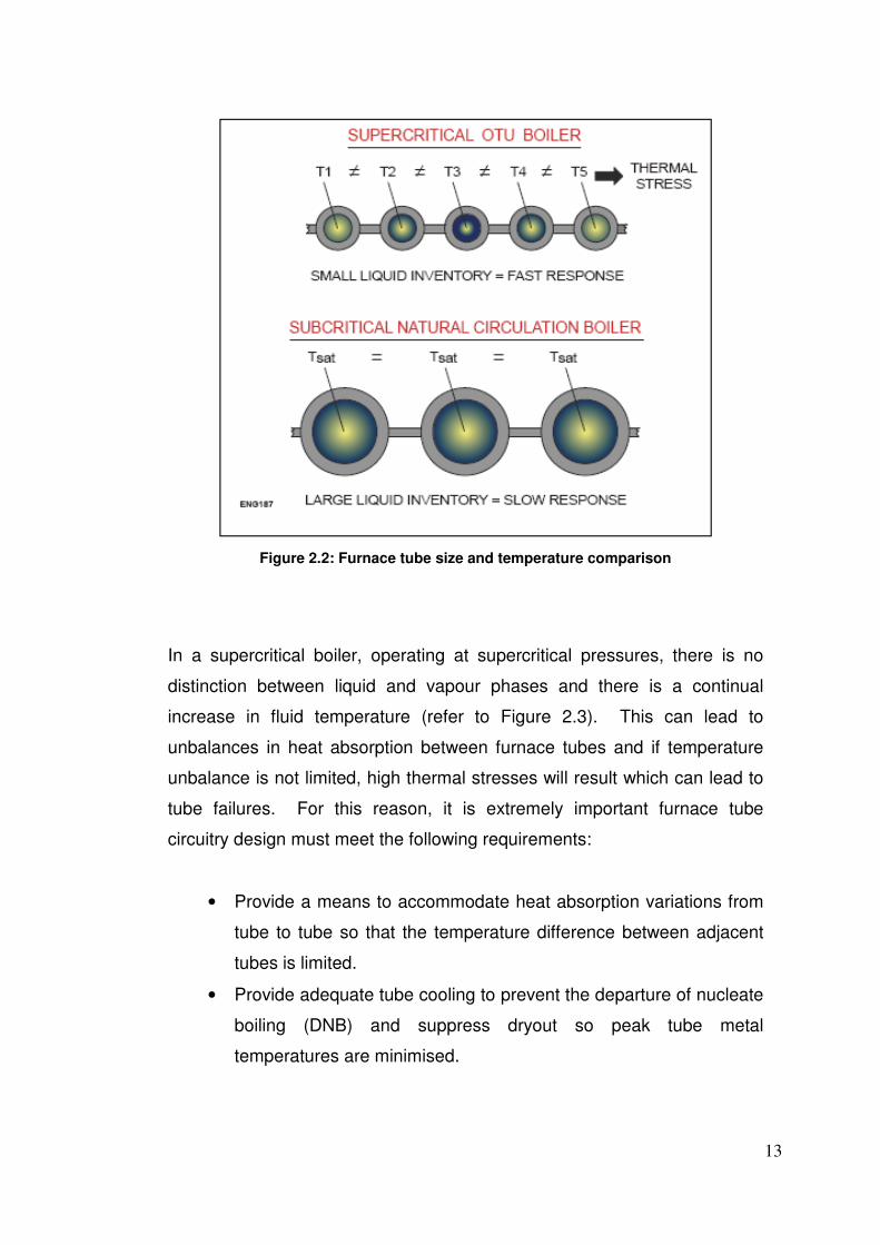
In a supercritical boiler, operating at supercritical pressures, there is no
distinction between liquid and vapour phases and there is a continual
increase in fluid temperature (refer to Figure 2.3). This can lead to
unbalances in heat absorption between furnace tubes and if temperature
unbalance is not limited, high thermal stresses will result which can lead to
tube failures. For this reason, it is extremely important furnace tube
circuitry design must meet the following requirements:
• Provide a means to accommodate heat absorption variations from
tube to tube so that the temperature difference between adjacent
tubes is limited.
• Provide adequate tube cooling to prevent the departure of nucleate
boiling (DNB) and suppress dryout so peak tube metal
temperatures are minimised.
14
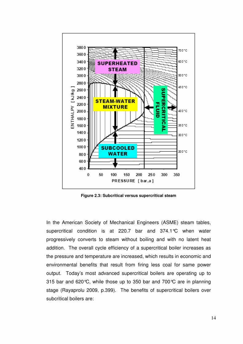
Figure 2.3: Subcritical versus supercritical steam
In the American Society of Mechanical Engineers (ASME) steam tables,
supercritical condition is at 220.7 bar and 374.1°C when water
progressively converts to steam without boiling and with no latent heat
addition. The overall cycle efficiency of a supercritical boiler increases as
the pressure and temperature are increased, which results in economic and
environmental benefits that result from firing less coal for same power
output. Today’s most advanced supercritical boilers are operating up to
315 bar and 620°C, while those up to 350 bar and 700°C are in planning
stage (Rayaprolu 2009, p.399). The benefits of supercritical boilers over
subcritical boilers are:
15
• Fuel savings due to higher cycle efficiency
• Reduction of CO2 emissions due to lower fuel input for the same
energy
• Superior load dynamics as the furnace tubes have smaller liquid
inventory and there is no water in circulation
• Part load performance improves with variable/sliding pressure
operation
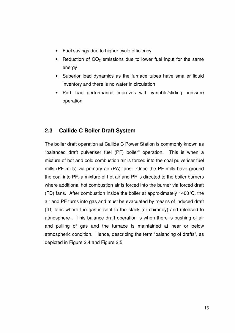
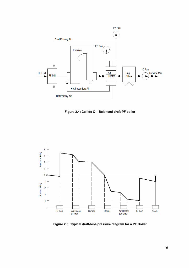
2.3 Callide C Boiler Draft System
The boiler draft operation at Callide C Power Station is commonly known as
“balanced draft pulveriser fuel (PF) boiler” operation. This is when a
mixture of hot and cold combustion air is forced into the coal pulveriser fuel
mills (PF mills) via primary air (PA) fans. Once the PF mills have ground
the coal into PF, a mixture of hot air and PF is directed to the boiler burners
where additional hot combustion air is forced into the burner via forced draft
(FD) fans. After combustion inside the boiler at approximately 1400°C, the
air and PF turns into gas and must be evacuated by means of induced draft
(ID) fans where the gas is sent to the stack (or chimney) and released to
atmosphere . This balance draft operation is when there is pushing of air
and pulling of gas and the furnace is maintained at near or below
atmospheric condition. Hence, describing the term “balancing of drafts”, as
depicted in Figure 2.4 and Figure 2.5.
16
Figure 2.4: Callide C – Balanced draft PF boiler
Figure 2.5: Typical draft-loss pressure diagram for a PF Boiler
17
2.4 Boiler Draft Efficiency and Design
Fans in a boiler plant are perhaps the most important of all auxiliary
equipment because they affect boiler performance, auxiliary power
consumption and boiler dynamics. Design factors such as fan margin and
fan type have a major role in boiler design and efficiency. It is important
thorough engineering must be sought when selecting boiler draft fans.
2.4.1 Fan Margins
Fan margin calculations are the most critical design aspect when selecting
correct fan size. Margins on volume, head, operating and ambient
temperatures are included into fan design conditions for calculating boiler
maximum continuous rating (MCR). Boiler draft fan margins are essential
for the following reasons:
• Safety margins for pressure and draft losses through the boiler draft
system are vital in ensuring MCR is always available.
• Ambient temperature variation of -5°C to +50°C in the tropics and -
20°C to +35°C in temperate climates, translates to a variation of
approximately 20% in the specific volume of air.
• Unpredictable fouling of surfaces increases pressure head,
particularly with fuels such as coal.
• Differences in boiler construction geometry compared with design
calculations due to inaccuracies in manufacturing and erection.
• Boiler systems that need over-firing to catch up with rapid load
ramps needs more power from the fans.
• Fan manufacturers have negative tolerances on head and volume
specifications that must be compensated for if all parameters are too
met in practice.
18
Fan margin figures are continuously being refined by design engineers to
avoid unnecessarily large margins that can lead to high capital costs and
excessive auxiliary power consumption. The general industry consensus
for draft fan margins in a coal fired boiler should be around (Rayaprolu
2009, p.313):
• 20% for volume
• 44% for variable pressure head
• 20% for operating temperature
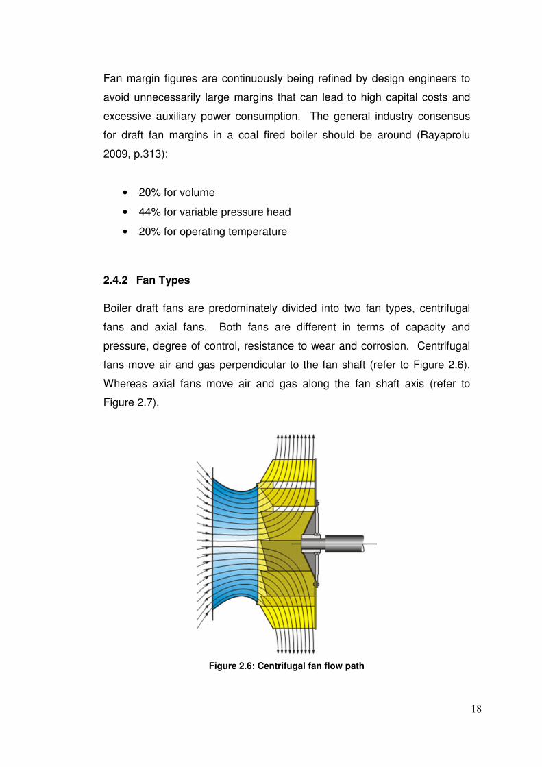
2.4.2 Fan Types
Boiler draft fans are predominately divided into two fan types, centrifugal
fans and axial fans. Both fans are different in terms of capacity and
pressure, degree of control, resistance to wear and corrosion. Centrifugal
fans move air and gas perpendicular to the fan shaft (refer to Figure 2.6).
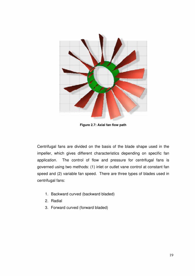
Whereas axial fans move air and gas along the fan shaft axis (refer to
Figure 2.7).
Figure 2.6: Centrifugal fan flow path
19
Figure 2.7: Axial fan flow path
Centrifugal fans are divided on the basis of the blade shape used in the
impeller, which gives different characteristics depending on specific fan
application. The control of flow and pressure for centrifugal fans is
governed using two methods: (1) inlet or outlet vane control at constant fan
speed and (2) variable fan speed. There are three types of blades used in
centrifugal fans:
1. Backward curved (backward bladed)
2. Radial
3. Forward curved (forward bladed)
20
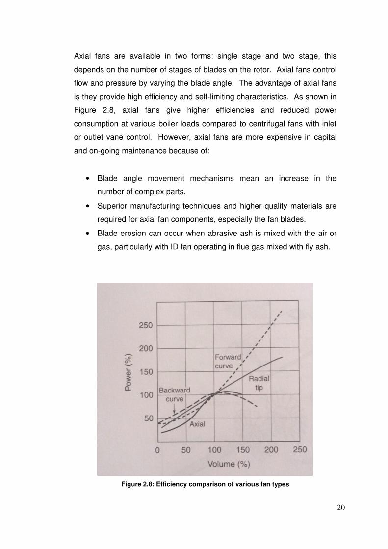
Axial fans are available in two forms: single stage and two stage, this
depends on the number of stages of blades on the rotor. Axial fans control
flow and pressure by varying the blade angle. The advantage of axial fans
is they provide high efficiency and self-limiting characteristics. As shown in
Figure 2.8, axial fans give higher efficiencies and reduced power
consumption at various boiler loads compared to centrifugal fans with inlet
or outlet vane control. However, axial fans are more expensive in capital
and on-going maintenance because of:
• Blade angle movement mechanisms mean an increase in the
number of complex parts.
• Superior manufacturing techniques and higher quality materials are
required for axial fan components, especially the fan blades.
• Blade erosion can occur when abrasive ash is mixed with the air or
gas, particularly with ID fan operating in flue gas mixed with fly ash.
Figure 2.8: Efficiency comparison of various fan types
21
2.5 Tribology of Rotating Machines
The theory of lubrication and bearing design in rotating machines falls
under the broader context of tribology. The term ‘tribology’, is the science
of mechanisms of friction, lubrication, and wear of interacting surfaces that
are in relative motion. Tribological components are those which carry all
the relative movements in rotating machines and their performance is a
critical contribution to reliability and efficiency. These components are the
local points where high forces and rapid movements are transmitted
simultaneously. They are also the components most likely to fail because
of the high concentration of energy that is carried at this point during normal
operation and particularly start-up. These components are the mechanical
fuses if a machine fails in service, therefore indicating a failure mode exists.
2.5.1 Bearing Design
Bearings in heavy rotating machines are divided into two categories: (1)
anti-friction bearings, better know as rolling element bearings and (2) fluid
film bearings, more commonly know as journal bearings or sleeve bearings.
Within these two categories, bearing load on the shaft is categorised by the
load direction: radial load, axial load and combination radial and axial load.
The axial load component (also referred to as thrust load) is in the direction
of the shaft axis, while the radial load component is in the direction normal
to the shaft axis (Harnoy 2003, p.3).
22
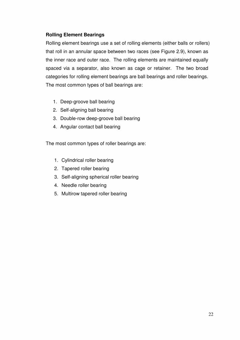
Rolling Element Bearings
Rolling element bearings use a set of rolling elements (either balls or rollers)
that roll in an annular space between two races (see Figure 2.9), known as
the inner race and outer race. The rolling elements are maintained equally
spaced via a separator, also known as cage or retainer. The two broad
categories for rolling element bearings are ball bearings and roller bearings.
The most common types of ball bearings are:
1. Deep-groove ball bearing
2. Self-aligning ball bearing
3. Double-row deep-groove ball bearing
4. Angular contact ball bearing
The most common types of roller bearings are:
1. Cylindrical roller bearing
2. Tapered roller bearing
3. Self-aligning spherical roller bearing
4. Needle roller bearing
5. Multirow tapered roller bearing
23
Figure 2.9: Typical ball bearing cross sections
Rolling elements bearing are becoming more common in today’s industries
mainly due to precision CNC machining capabilities and advances in
material metallurgy. These bearings offer the following advantages when
compared with journal bearings: (1) less friction at starting and general
operation, (2) less sensitive to lubrication interruptions, (3) suitable for high
precision applications and (4) more suitable for supporting combination
radial and axial loads. However, the disadvantages are: (1) require more
space in the radial direction and (2) repeated cycle stresses at ball-to-race
contact creates a finite fatigue life.
24
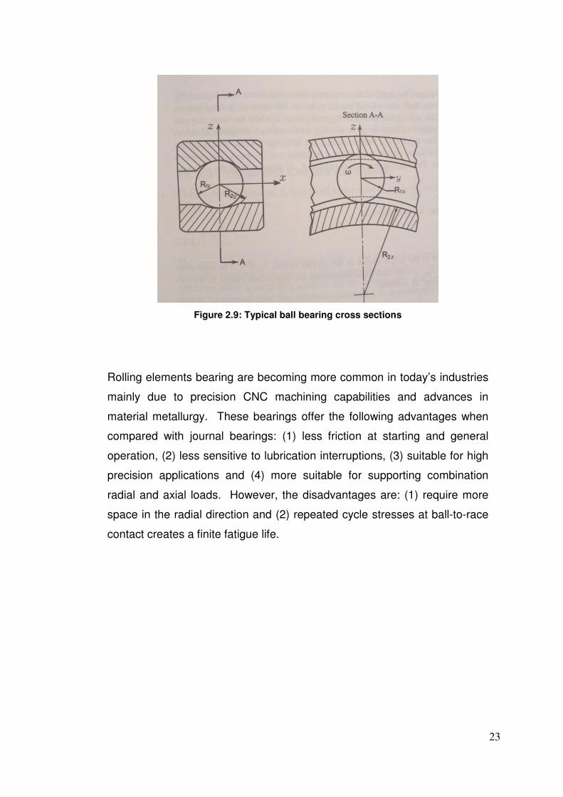
Journal Bearings
A journal bearing (or tilting pad bearing) is where the journal is rotating
inside the bore of a sleeve with a thin clearance. There is a continuous
fluid film running in this clearance which separates the solid surfaces and
provides load-carrying capacity, hence the terminology fluid film bearings.
There are two principal methods of creating and maintaining a load-carrying
film between solid surfaces in relative motion (Szeri 1998, p.33). A journal
bearing that creates self-acting lubrication operates in ‘hydrodynamic’ mode.
This is when the fluid film is generated and maintained by a wedge of
viscous lubricant drawn into the clearance between the two converging
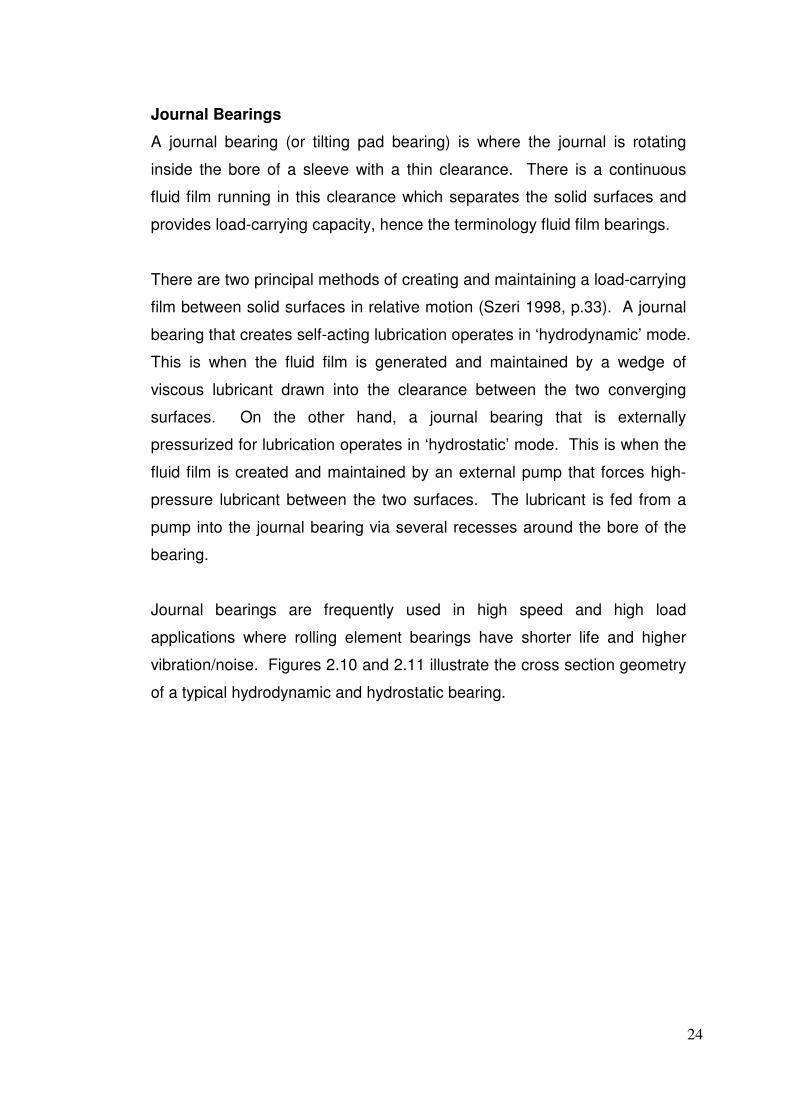
surfaces. On the other hand, a journal bearing that is externally
pressurized for lubrication operates in ‘hydrostatic’ mode. This is when the
fluid film is created and maintained by an external pump that forces high-
pressure lubricant between the two surfaces. The lubricant is fed from a
pump into the journal bearing via several recesses around the bore of the
bearing.
Journal bearings are frequently used in high speed and high load
applications where rolling element bearings have shorter life and higher
vibration/noise. Figures 2.10 and 2.11 illustrate the cross section geometry
of a typical hydrodynamic and hydrostatic bearing.
25
Figure 2.10: Hydrodynamic journal bearing cross section
Figure 2.11: Hydrostatic journal bearing cross section
26
Hydrodynamic bearings are very popular in heavy rotating machines due to
their simplistic design and low costs as there is no external high-pressure
pump system to install and maintain. One of major disadvantages of
hydrodynamic bearings is that a certain minimum angular velocity is
required to generate a complete fluid film that completely separates the two
surfaces. For this reason, these bearings are not suitable for variable
speed drives and excessive stopping and starting applications. In particular,
hydrodynamic bearings undergo severe wear during start-up, when they
accelerate from zero speed, because static friction is higher than dynamic
friction (Harnoy 2003, p.9).
To eliminate the wear problems associated with hydrodynamic bearings,
externally pressurized hydrostatic bearings ensures a complete fluid film
separates the two surfaces at all speeds, including zero speed. This makes
hydrostatic bearings well suited for rotating machines requiring frequent
stopping and starting cycles and variable speed. Another advantage of
hydrostatic bearings is their good stiffness to radial loads due to the
constant pressure fluid film between two solid surfaces. This high stiffness
of radial displacement makes this bearing suitable for precision machines,
such as precise machine tools. The disadvantages of hydrostatic bearings
when compared with hydrodynamic bearings are: (1) higher initial cost, (2)
requirement for high-pressure external pump and (3) greater risk of
lubrication failure because of failure of external pump.
27
2.5.2 Callide C ID Fan and Electric Motor Bearings
The Callide C ID fans and electric induction motors utilize both rolling
element bearings and journal bearings. The induction motors use a split-
sleeve hydrodynamic bearing on both drive end (DE) and non-drive end
(NDE). This bearing type is ideal for heavy electric drive applications due
to high radial loads, high speeds, simplistic design, constant speed and
infrequent stop and start cycles.
The fan main shaft assembly uses single-flange cylindrical roller bearings
on both DE and NDE for high radial loads created from the fan rotor and
blades. This bearing type is designed for high radial load and low axial load
carry capacity. A spherical roller thrust bearing is also used on the NDE for
high axial loads created from the axial fan thrust. This bearing type is
designed for high axial load and low radial load carry capacity. The fan
main shaft bearings provide precision alignment of critical rotating
components and can withstand a combination of high radial and axial loads.
2.5.3 Lubrication Theory
A lubricant is a gas, liquid, or solid that is used to prevent contact of parts in
relative motion, reducing friction and wear (Mobley 1999, p.55). Lubricants
also perform other important functions such as: machine cooling, rust
prevention, preventing the deposition of solids on close-fitting parts, and
power transmission.
Lubrication is an important part in the efficiency and reliability of rotating
machines which is under ever increasing scrutiny in today’s economic
climate. Engineers are continuously improving lubrication systems in an
attempt to increase productivity, more cost effective. Correct lubricant
selection and lubrication system design is vital in achieving a cost effective
and reliable machine.
28
Of the three lubricant types listed above, liquid lubricant is the most
commonly used in heavy rotating machines. Liquid lubricants have many
advantages over solid and gas lubricants. The most important advantages
of liquid lubricants are the formation of hydrodynamic films, the cooling of
the bearing by effective convection heat transfer, and finally their relative
convenience for use in bearings (Harnoy 2003, p.47). The most common
liquid lubricants are minerals oil, which are produced from petroleum
(Harnoy 2003, p.47). Mineral oils typically contain greater than 90% base
oil and less than 10% additives. Oil additives are used to improve base oil
characteristics, such as:
• Minimise lubricant oxidation
• Maintain thermal stability at high temperatures
• Provide good water separation properties
• Protect contact surfaces against corrosion
• Improve viscosity index (VI)
• Improve low-temperature characteristics
• Provide a wear-resistance film on all contact surfaces
• Maintain cleanliness of components
• Reduce air entrainment and foaming
• Improve wear resistance under extreme pressure (EP)
29
2.5.4 Fluid Film Lubrication
Fluid film lubrication in bearings is commonly divided into two categories:
thin-film lubrication and thick-film lubrication. A thick-film lubrication
condition is when the coefficient of friction between the two surfaces is
small and depends on no other material property of the lubricant than its
bulk viscosity. In many respects, this type of lubrication is the simplest and
most desirable as friction coefficient is very low (i.e. 0.0001) and there is
complete separation between the two solid surfaces. Thus, this form of
lubrication is encountered in both hydrodynamic and hydrostatic bearings.
A thin-film lubrication condition is when the fluid film thickness is 1 µm or
less, usually encountered in rolling element bearings where there is
counter-formal contact of the rolling element and race. This type of
lubrication has a higher friction coefficient (i.e. 0.05 – 0.15) which depends
on the surface roughness, bearing material properties and lubricant
properties.
2.5.5 Callide C ID Fan Lubrication
As highlighted above, the importance oil selection with the proper additives
is crucial in all lubrication systems. The oil used in Callide C ID fan
lubrication system is Shell Tellus S 46, which is a zinc-free hydraulic oil
used for severe conditions. The Shell Tellus S oil range is a ‘top-tier’ anti-
wear hydraulic oil formulated to provide exceptional performance in
hydraulic fluid power transmission subjected to severe duty. One of the
most important performance benefits is long life due to its excellent
oxidation properties, between two to four times that of other anti-wear
hydraulic oils. Extended oil life depends on its ability to resist oxidation due
to heat in the presence of air, water and metal catalysts such as copper
(Shell Product Data Sheet 2009). Refer to Table 2.1 for Shell Tellus S 46
oil properties.
30
Table 2.1 – Shell Tellus S 46 oil properties

31
Chapter 3 – Methodology
3.1 Further Research and Appraisal
Before investigation effort is conducted into the operational and reliability
failure modes in the existing ID fan lubrication system, further research and
appraisal is required on the different types of bearings and lubrication used
in large electric drives and axial fans. This process is crucial in identifying
any inherent bearing/lubrication design defects in the ID fans and electric
induction motors.
3.1.1 Bearing Selection
The decision between which bearing type to use in a particular application
is not always easy or even obvious. The ‘best’ bearing decision depends
on the details of the particular application and weighing up the advantages
and disadvantages of journal bearings and rolling element bearings. The
choice of bearing arrangement is based on the following key aspects:
• Load carry capacity in the axial and radial direction
• Rotating speed
• Over speed and duration
• Operating temperature
• Environmental conditions
• Lubrication selection
• Bearing operational hours
32
The main shaft (rotor) assembly for both axial fans and inductions motors
can be purchased with either rolling element or journal bearings. Both
bearing systems have proven their valve and reliability in many installations
over the years, therefore the decision between journal bearing and anti-
friction bearing is often philosophical. Both designs have different
performance characteristics and inherent maintenance and reliability
differences. The initial cost of the journal bearing is much greater than the
rolling element bearing design, but this may not be as significant when you
take into account the total life cycle cost (Finley & Hodowanec 2001).
Journal bearings, either split-sleeve or tilting pad configuration are
commonly used in heavy rotating machines were large diameter rotors are
sought. As larger rotor sizes are encountered, larger shaft diameters will
have to be used to keep torsional shaft stresses within acceptable levels.
However, as shaft size (and thus bearing size) goes up, the bearing speed
limit goes down. Eventually the required shaft size will result in anti-friction
bearings that have a lower bearing speed limit than operational speed of
the machine (Finley & Hodowanec 2001). This is the transition point where
a journal bearing is required for this particular application.
In small induction motors 150 kW or less, there is no choice in bearing
selection as only rolling element bearings are readily available for small
shaft diameters. Likewise, a choice does not always exist on larger motors
above 1500 kW as various design requirements leave only the journal
bearing (or tilting pad bearing) as a viable option. As a result, a suitable
bearing choice for intermediate size motors between 150 kW and 1500 kW
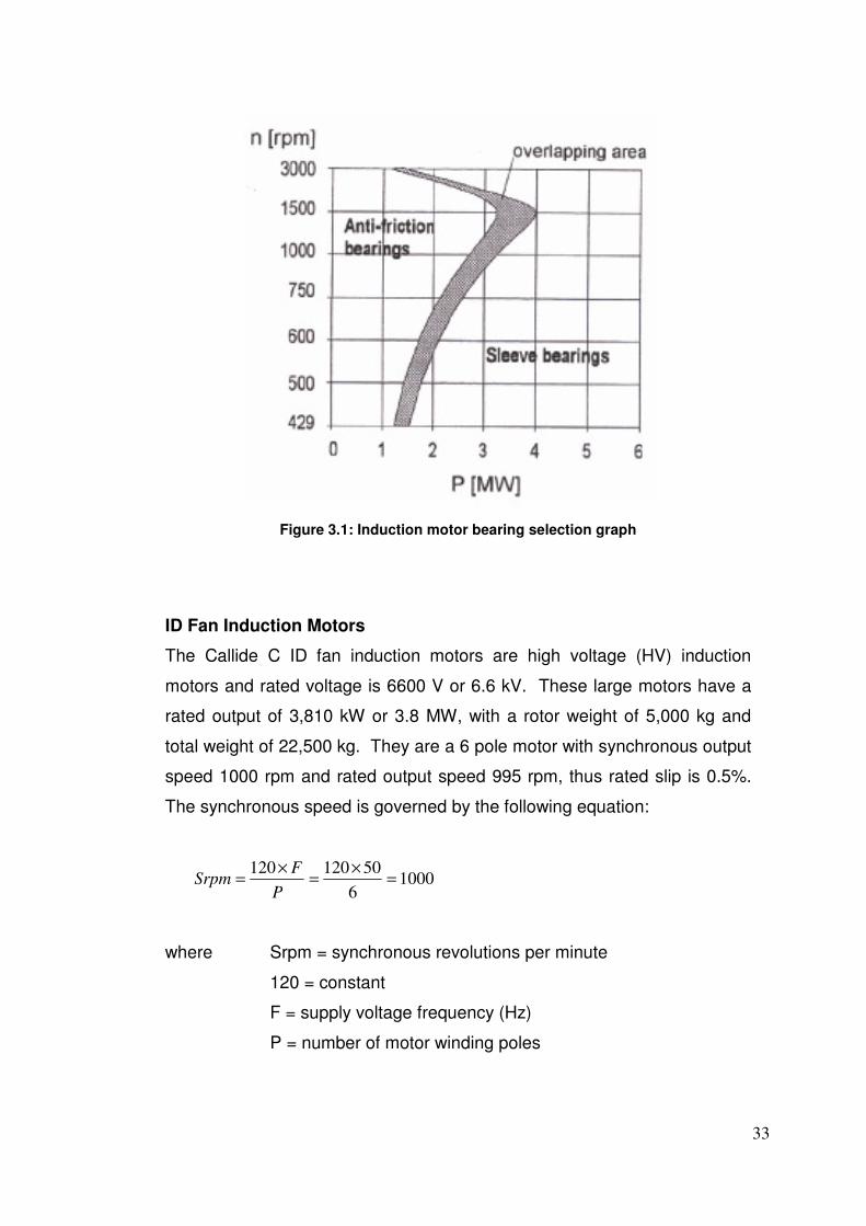
is often made by the design engineers. The bearing selection graph shown
in Figure 3.1 gives a guide into correct bearing selection for different motor
size and operating speed (Hoppler & Errath 2007).
33
Figure 3.1: Induction motor bearing selection graph
ID Fan Induction Motors
The Callide C ID fan induction motors are high voltage (HV) induction
motors and rated voltage is 6600 V or 6.6 kV. These large motors have a
rated output of 3,810 kW or 3.8 MW, with a rotor weight of 5,000 kg and
total weight of 22,500 kg. They are a 6 pole motor with synchronous output
speed 1000 rpm and rated output speed 995 rpm, thus rated slip is 0.5%.
The synchronous speed is governed by the following equation:
10006
50120120=
×=
×=
P
FSrpm
where Srpm = synchronous revolutions per minute
120 = constant
F = supply voltage frequency (Hz)
P = number of motor winding poles
34
As mentioned earlier in Chapter 2, the ID fan induction motors use a split-
sleeve journal hydrodynamic bearing on the DE and NDE. Due to the large
size and heavy weight of these motors, the existing bearing arrangement is
correct and fit-for-purpose. This is further justified using Figure 3.1, as it
shows a 3.8 MW electric motor running at 995 rpm is recommended to use
sleeve bearings (also known as journal bearings).
Another important aspect of split-sleeve journal bearings is their user-
friendliness for maintainability and replacement. Split-sleeve means the
bearing is manufactured as two identical semicircle pieces which form
together to provide a full 360 degree bearing. The biggest advantage of
this feature when compared with one-piece journal bearings or rolling
element bearings is that the shaft does not need to be separated from the
machine for bearing inspection or replacement. This allows all bearing
maintenance to be conducted in-situ, which is a huge time and cost saving
benefit for large and heavy rotating machines.
ID Fan Main Shaft
The Callide C ID fans are Howden Variax dual-stage axial fans which are
designed to operate at 88% efficiency at design volume flow rate 350 m3/s.
These fans are quite large in physical size with an impeller outer diameter
2700 mm and hub outer diameter 1500 mm.
As stated in Chapter 2, the ID fan main shaft bearings consist of two single-
flange cylindrical roller bearings and a spherical roller thrust bearing. This
type of rolling element bearing arrangement offers distinguishing
advantages compared to journal bearings in the same application. Rolling
element bearings provide superior emergency operation in the event of
lubrication interruptions to the bearing sump. They also permit precision
tolerances for critical rotating parts and are more suitable for supporting
high axial and radial loads. Given this information, the current bearing
arrangement for the ID fan main shaft is also correct and fit-for-purpose.

35
3.1.2 Lubrication Selection
Correct lubrication selection is just a vital as correct bearing selection.
Lubrication for rolling element bearings and journal bearings in axial fans
and induction motors is commonly divided into two categories: (1) oil
lubrication and (2) grease lubrication. Oil is classed as a liquid lubricant
and grease is defined as a semi-fluid lubricant. Basically, a grease
lubricant is a liquid lubricant that is mixed with another thickener substance
(i.e. soap) to form a semi-fluid. This gives grease a higher viscosity than oil,
which is very useful for infrequent lubrication applications where oil
lubrication is neither practical nor feasible. The decision between oil or
grease lubricant depends on the details of the particular application and
weighing up their advantages and disadvantages. The choice of lubricant
type is based on the following key aspects:
• Bearing type and speed limit
• Bearing operating temperature
• Required bearing cooling rate
• Bearing operational hours
• Environmental conditions
36
ID Fan Induction Motors
Because the Callide C ID fan induction motors currently run with
hydrodynamic journal bearings, there is no choice other than oil lubrication
for this application. These bearings require oil lubrication to provide a fluid
film which separates the solid surfaces and provides load-carrying capacity.
Hydrodynamic journal bearings usually require flood (or force fed)
lubrication systems as this ensures oil circulation is maintained to provide
cooling of bearing. The flood lubrication system must be able to deliver a
predetermined volume flow rate of oil at a certain pressure to ensure
maximum bearing life. Oil rings are oftentimes used to provide oil
circulation in the bearing sump in the event that the flood lubrication system
fails. This redundant feature will enable the induction motor to safety coast
down shaft speed to a stand still without causing severe bearing damage.
The lubrication design on the ID fan induction motors uses all the aspects
as listed above, therefore proving current design is correct and fit-for-
purpose. The current design is oil flood lubrication via an external
lubrication system and oil rings are also used for redundancy. The only key
component that is absent is no oil flow monitoring in the current system to
ensure volumetric flow rate is maintained as per OEM recommendations.
ID Fan Main Shaft
Unlike the induction motor journal bearings which must employ oil
lubrication, rolling element bearings have the choice between oil and
grease lubrication. The choice between oil and grease lubrication in axial
fans with rolling element bearings is dependant fan application.
Axial fans with grease lubricated bearings have a lower initial cost
compared to oil lubricated bearings. However grease lubrication requires
more ongoing routine maintenance and can be very problematic. Common
problems are over-lubrication, under-lubrication and lack of cleanliness
during re-lubrication, which all impact on reliability and maintenance costs.

37
Grease lubrication is also very limited in providing cooling of the bearing as
there is no volumetric flow of fluid to permit effective convection heat
transfer. For this reason, axial fans operating with grease lubrication are
primarily designed for ambient temperature applications as the bearings are
located in the gas flow path. This is typical in FD fan and PA fan
applications where an axial fan is used to supply ambient temperature air to
the boiler.
On the other hand, axial fans that are designed for applications which
operate above ambient temperatures must have some form of bearing
cooling. The most common form of bearing cooling is oil flood lubrication
as volumetric flow of oil provides cooling of the bearing. This is typical in ID
fan applications where an axial fan is designed to remove hot gas between
120°C to 150°C from the boiler. Callide C ID fan main shaft bearings are
running oil flood lubrication for this reason, therefore proving the current
design is correct and fit-for-purpose. Again, as explained previously, the
main factor that is absent is no oil flow monitoring in the current system to
ensure volumetric flow rate is maintained as per OEM recommendations.
38
3.2 Root Cause Analysis Methodology
Root Cause Analysis (RCA) is a tool used to identify and define root causes
and their associated failure modes. This method is critical as it ensures the
correct failure modes are determined so the root causes can be eliminated.
Close adherence to this process avoids “solving the wrong problem”, which
is evident when the flow transmitters were replaced with pressure
transmitters back in 2004. The Apollo RCA process developed by Apollo
Associated Services will be adopted for this project as it is CS Energy’s
preferred method. The Apollo RCA process is a 4-step method (Gano 2003,
p.55):
1. Define the Problem
2. Create an Apollo Cause and Effect Chart
3. Identify Effective Solutions
4. Implement the Best Solutions
The first step to make certain the RCA process obtains common agreement
on the root causes is to define a “problem statement”. A problem should
contain (Gano 2003, p.63):
• What is the problem?
• When did it happen?
• Where did it happen?
• What is the significance of the problem?
This gives
• What – Lubrication system trips ID fan
• When – Since commissioning in 2001
• Where – Callide C ID fans
• Significance – Has caused 11 ID fan trips and a loss of 7800
Megawatt hours (MWh) from 2004
39
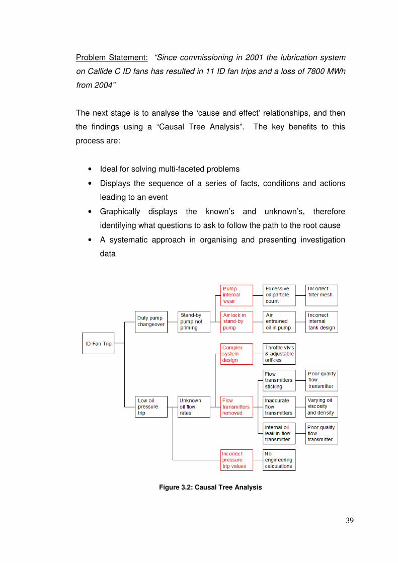
Problem Statement: “Since commissioning in 2001 the lubrication system
on Callide C ID fans has resulted in 11 ID fan trips and a loss of 7800 MWh
from 2004”
The next stage is to analyse the ‘cause and effect’ relationships, and then
the findings using a “Causal Tree Analysis”. The key benefits to this
process are:
• Ideal for solving multi-faceted problems
• Displays the sequence of a series of facts, conditions and actions
leading to an event
• Graphically displays the known’s and unknown’s, therefore
identifying what questions to ask to follow the path to the root cause
• A systematic approach in organising and presenting investigation
data
Figure 3.2: Causal Tree Analysis
40
Figure 3.2 highlights all failure modes and root causes which have been
causing problems in the ID fan lubrication system. The causal tree analysis
also shows the complex nature of identifying all problems which contribute
to the root causes. The five primary causes are:
1. Pump internal wear
2. Airlock in stand-by pump
3. Complex system design
4. Flow transmitters removed
5. Incorrect pressure trip values
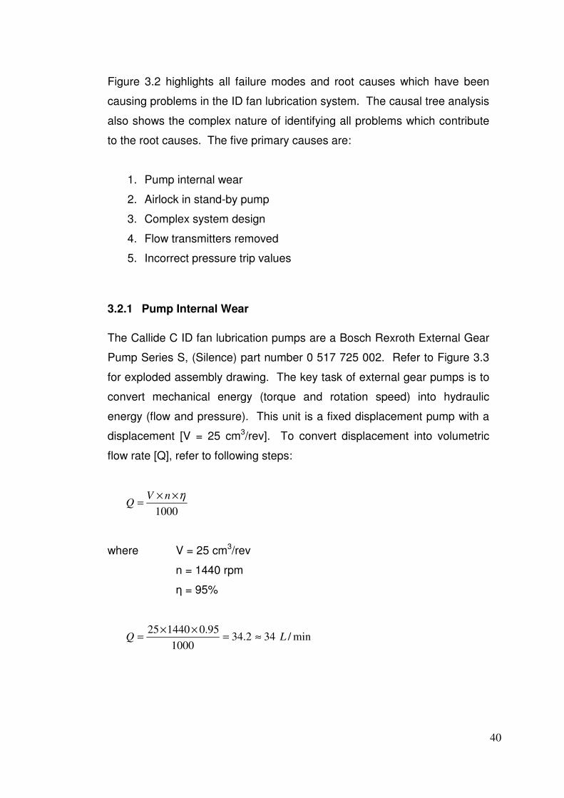
3.2.1 Pump Internal Wear
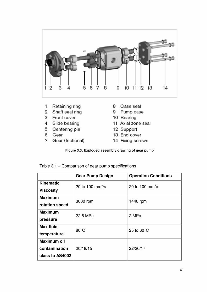
The Callide C ID fan lubrication pumps are a Bosch Rexroth External Gear
Pump Series S, (Silence) part number 0 517 725 002. Refer to Figure 3.3
for exploded assembly drawing. The key task of external gear pumps is to
convert mechanical energy (torque and rotation speed) into hydraulic
energy (flow and pressure). This unit is a fixed displacement pump with a
displacement [V = 25 cm3/rev]. To convert displacement into volumetric
flow rate [Q], refer to following steps:
1000
η××=
nVQ
where V = 25 cm3/rev
n = 1440 rpm
ƞ = 95%
min/342.341000
95.0144025LQ ≈=
××=
41
Figure 3.3: Exploded assembly drawing of gear pump
Table 3.1 – Comparison of gear pump specifications
Gear Pump Design Operation Conditions
Kinematic
Viscosity 20 to 100 mms/s 20 to 100 mms/s
Maximum
rotation speed 3000 rpm 1440 rpm
Maximum
pressure 22.5 MPa 2 MPa
Max fluid
temperature 80°C 25 to 60°C
Maximum oil
contamination
class to AS4002
20/18/15 22/20/17

42
Table 3.1 compares the gear pump design specification against the
operation conditions. This shows operating conditions of kinematic
viscosity, rotation speed, pressure and fluid temperature are within the gear
pump design parameters. However the operating oil cleanliness code
22/20/17 to AS4002.1 exceeds the gear pump maximum allowable
cleanliness code 20/18/15. The cleanliness code for operating conditions
was conducted using oil samples in June 2010. The samples were sent to
ASL Tribology for results.
AS4002.1 is an Australian Standard: “Hydraulic fluid power – Particulate
contamination of systems, Part 1: Method for coding the level of
contamination”. The code for contamination levels using automatic particle
counters comprises of three scale numbers, which permit the differentiation
of the dimension and the distribution of the particles as follows (Australian
Standards, 2001):
1. the first scale number represents the number of particles equal to or
larger than 4 µm per millilitre of fluid;
2. the second scale number represents the number of the particles
equal to or larger than 6 µm per millilitre of fluid;
3. the third scale number represents the number of the particles equal
to or larger than 14 µm per millilitre of fluid.
The scale numbers are allocated according to the number of particles
counted per millilitre of the fluid sample, refer to AS4002.1 page 3.
EXAMPLE: A code 22/20/17 signifies that there are more than 20,000 and
up to and including 40,000 particles equal to or larger than 4 µm, more than
5,000 and up to and including 10,000 particles equal to or larger than 6 µm
and more than 640 and up to and including 1,300 particles equal to or
larger than 14 µm in 1 millilitre (ml) of a given fluid sample.
43
Table 3.2 – Comparison of oil particle contamination
AS4002.1 Gear Pump Design
(20/18/15)
Operation Conditions
(22/20/17)
First scale
number ≥ 4 µm 5,000 to 10,000 particles 20,000 to 40,000 particles
First scale
number ≥ 6 µm 1,300 to 2,500 particles 5,000 to 10,000 particles
First scale
number ≥ 14 µm 160 to 320 particles 640 to 1,300 particles
Table 3.2 gives a comparison of particle contamination with gear pump
design versus current operation conditions. This shows the current oil
particle contamination is a factor of four times greater than allowable, which
dramatically decreases gear pump life and increases internal wear. To
determine the extent of wear in the gear pumps, all Callide C ID fan
lubrication pumps were replaced in June/July 2010 and disassembled for
internal inspection.
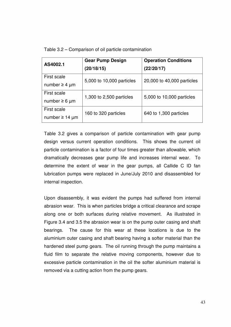
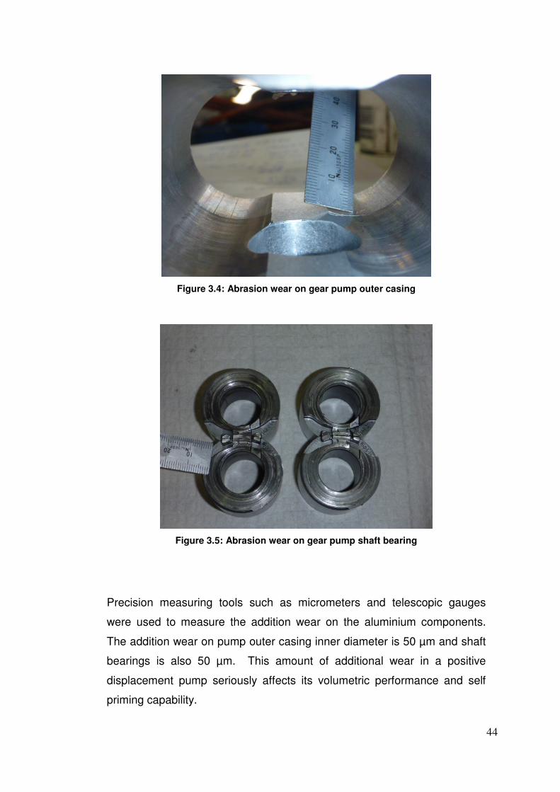
Upon disassembly, it was evident the pumps had suffered from internal
abrasion wear. This is when particles bridge a critical clearance and scrape
along one or both surfaces during relative movement. As illustrated in
Figure 3.4 and 3.5 the abrasion wear is on the pump outer casing and shaft
bearings. The cause for this wear at these locations is due to the
aluminium outer casing and shaft bearing having a softer material than the
hardened steel pump gears. The oil running through the pump maintains a
fluid film to separate the relative moving components, however due to
excessive particle contamination in the oil the softer aluminium material is
removed via a cutting action from the pump gears.
44
Figure 3.4: Abrasion wear on gear pump outer casing
Figure 3.5: Abrasion wear on gear pump shaft bearing
Precision measuring tools such as micrometers and telescopic gauges
were used to measure the addition wear on the aluminium components.
The addition wear on pump outer casing inner diameter is 50 µm and shaft
bearings is also 50 µm. This amount of additional wear in a positive
displacement pump seriously affects its volumetric performance and self
priming capability.
45
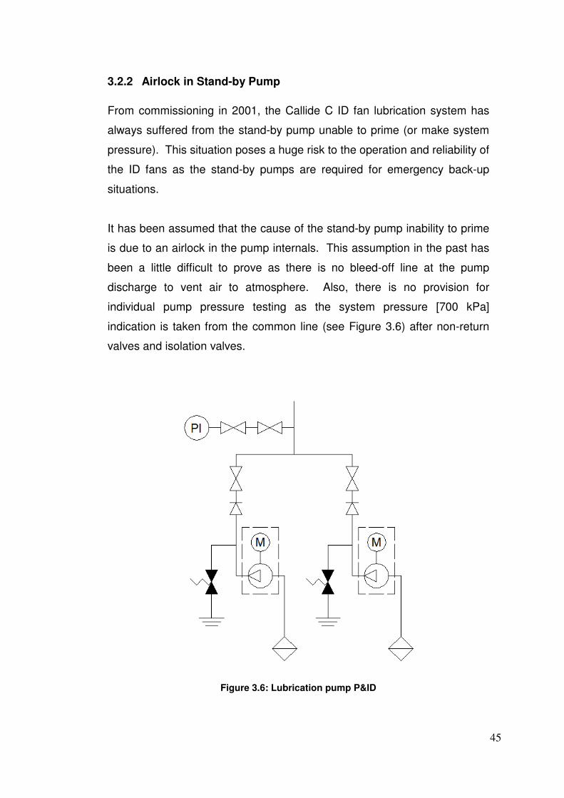
3.2.2 Airlock in Stand-by Pump
From commissioning in 2001, the Callide C ID fan lubrication system has
always suffered from the stand-by pump unable to prime (or make system
pressure). This situation poses a huge risk to the operation and reliability of
the ID fans as the stand-by pumps are required for emergency back-up
situations.
It has been assumed that the cause of the stand-by pump inability to prime
is due to an airlock in the pump internals. This assumption in the past has
been a little difficult to prove as there is no bleed-off line at the pump
discharge to vent air to atmosphere. Also, there is no provision for
individual pump pressure testing as the system pressure [700 kPa]
indication is taken from the common line (see Figure 3.6) after non-return
valves and isolation valves.
Figure 3.6: Lubrication pump P&ID
46
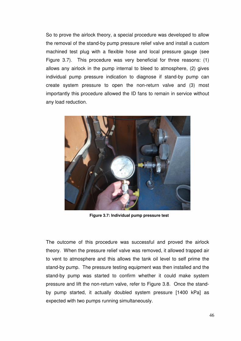
So to prove the airlock theory, a special procedure was developed to allow
the removal of the stand-by pump pressure relief valve and install a custom
machined test plug with a flexible hose and local pressure gauge (see
Figure 3.7). This procedure was very beneficial for three reasons: (1)
allows any airlock in the pump internal to bleed to atmosphere, (2) gives
individual pump pressure indication to diagnose if stand-by pump can
create system pressure to open the non-return valve and (3) most
importantly this procedure allowed the ID fans to remain in service without
any load reduction.
Figure 3.7: Individual pump pressure test
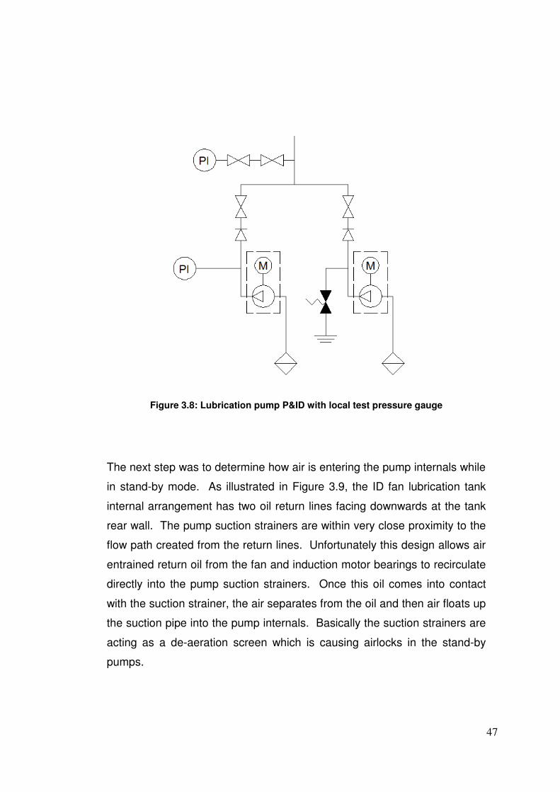
The outcome of this procedure was successful and proved the airlock
theory. When the pressure relief valve was removed, it allowed trapped air
to vent to atmosphere and this allows the tank oil level to self prime the
stand-by pump. The pressure testing equipment was then installed and the
stand-by pump was started to confirm whether it could make system
pressure and lift the non-return valve, refer to Figure 3.8. Once the stand-
by pump started, it actually doubled system pressure [1400 kPa] as
expected with two pumps running simultaneously.
47
Figure 3.8: Lubrication pump P&ID with local test pressure gauge
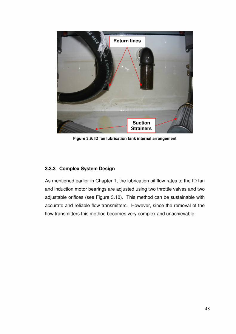
The next step was to determine how air is entering the pump internals while
in stand-by mode. As illustrated in Figure 3.9, the ID fan lubrication tank
internal arrangement has two oil return lines facing downwards at the tank
rear wall. The pump suction strainers are within very close proximity to the
flow path created from the return lines. Unfortunately this design allows air
entrained return oil from the fan and induction motor bearings to recirculate
directly into the pump suction strainers. Once this oil comes into contact
with the suction strainer, the air separates from the oil and then air floats up
the suction pipe into the pump internals. Basically the suction strainers are
acting as a de-aeration screen which is causing airlocks in the stand-by
pumps.
48
Figure 3.9: ID fan lubrication tank internal arrangement
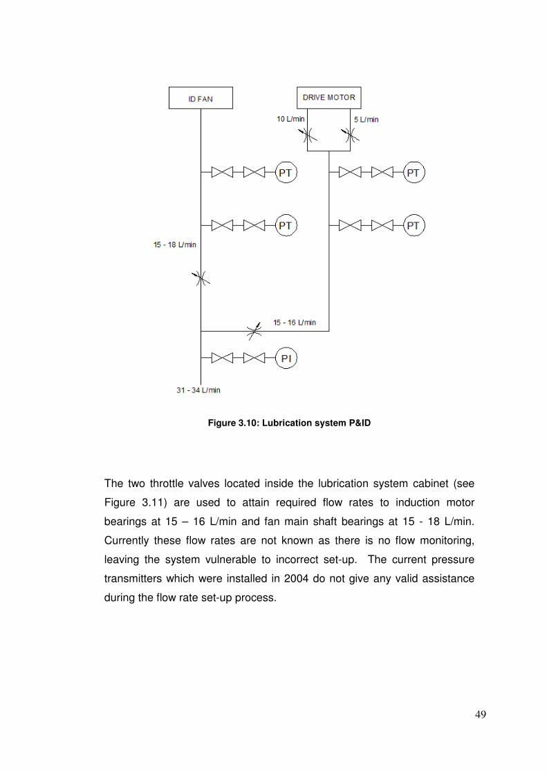
3.3.3 Complex System Design
As mentioned earlier in Chapter 1, the lubrication oil flow rates to the ID fan
and induction motor bearings are adjusted using two throttle valves and two
adjustable orifices (see Figure 3.10). This method can be sustainable with
accurate and reliable flow transmitters. However, since the removal of the
flow transmitters this method becomes very complex and unachievable.
Return lines
Suction Strainers
49
Figure 3.10: Lubrication system P&ID
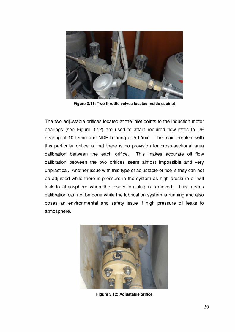
The two throttle valves located inside the lubrication system cabinet (see
Figure 3.11) are used to attain required flow rates to induction motor
bearings at 15 – 16 L/min and fan main shaft bearings at 15 - 18 L/min.
Currently these flow rates are not known as there is no flow monitoring,
leaving the system vulnerable to incorrect set-up. The current pressure
transmitters which were installed in 2004 do not give any valid assistance
during the flow rate set-up process.
50
Figure 3.11: Two throttle valves located inside cabinet
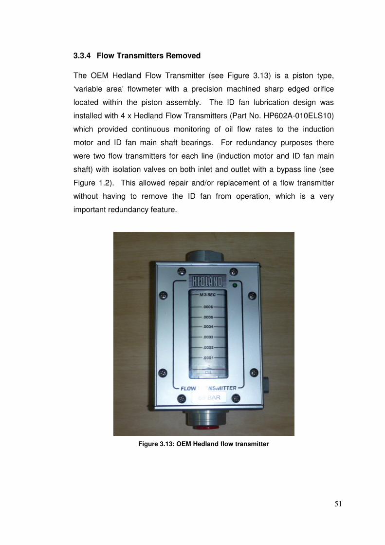
The two adjustable orifices located at the inlet points to the induction motor
bearings (see Figure 3.12) are used to attain required flow rates to DE
bearing at 10 L/min and NDE bearing at 5 L/min. The main problem with
this particular orifice is that there is no provision for cross-sectional area
calibration between the each orifice. This makes accurate oil flow
calibration between the two orifices seem almost impossible and very
unpractical. Another issue with this type of adjustable orifice is they can not
be adjusted while there is pressure in the system as high pressure oil will
leak to atmosphere when the inspection plug is removed. This means
calibration can not be done while the lubrication system is running and also
poses an environmental and safety issue if high pressure oil leaks to
atmosphere.
Figure 3.12: Adjustable orifice
51
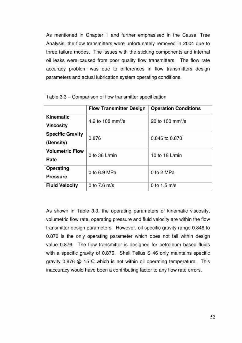
3.3.4 Flow Transmitters Removed
The OEM Hedland Flow Transmitter (see Figure 3.13) is a piston type,
‘variable area’ flowmeter with a precision machined sharp edged orifice
located within the piston assembly. The ID fan lubrication design was
installed with 4 x Hedland Flow Transmitters (Part No. HP602A-010ELS10)
which provided continuous monitoring of oil flow rates to the induction
motor and ID fan main shaft bearings. For redundancy purposes there
were two flow transmitters for each line (induction motor and ID fan main
shaft) with isolation valves on both inlet and outlet with a bypass line (see
Figure 1.2). This allowed repair and/or replacement of a flow transmitter
without having to remove the ID fan from operation, which is a very
important redundancy feature.
Figure 3.13: OEM Hedland flow transmitter
52
As mentioned in Chapter 1 and further emphasised in the Causal Tree
Analysis, the flow transmitters were unfortunately removed in 2004 due to
three failure modes. The issues with the sticking components and internal
oil leaks were caused from poor quality flow transmitters. The flow rate
accuracy problem was due to differences in flow transmitters design
parameters and actual lubrication system operating conditions.
Table 3.3 – Comparison of flow transmitter specification
Flow Transmitter Design Operation Conditions
Kinematic
Viscosity 4.2 to 108 mms/s 20 to 100 mms/s
Specific Gravity
(Density) 0.876 0.846 to 0.870
Volumetric Flow
Rate 0 to 36 L/min 10 to 18 L/min
Operating
Pressure 0 to 6.9 MPa 0 to 2 MPa
Fluid Velocity 0 to 7.6 m/s 0 to 1.5 m/s
As shown in Table 3.3, the operating parameters of kinematic viscosity,
volumetric flow rate, operating pressure and fluid velocity are within the flow
transmitter design parameters. However, oil specific gravity range 0.846 to
0.870 is the only operating parameter which does not fall within design
value 0.876. The flow transmitter is designed for petroleum based fluids
with a specific gravity of 0.876. Shell Tellus S 46 only maintains specific
gravity 0.876 @ 15°C which is not within oil operating temperature. This
inaccuracy would have been a contributing factor to any flow rate errors.
53
Also, the volumetric flow rate range 0 – 36 L/min for the flow transmitter is
double the operating condition range 10 – 18 L/min. This excessive range
means the flow transmitter is only operating in the lower half range which
means the incremental device range can be too coarse for required
accuracy. A flow transmitter with a range say of 2 - 22 L/min would have
given improved accuracy for this particular application.
3.3.5 Incorrect Pressure Trip Values
In 2004, an engineering consultancy was approached by CS Energy to
provide an engineering solution for the on-going issues which plagued the
operation and reliability of Callide C ID fans. From this, the design and
implementation of an engineering modification project was completed in
2004. The project involved removing the 4 x flow transmitters from each ID
fan lubrication system and replacing with 4 x pressure transmitters. The
ICMS alarm and trip parameters were also modified from oil flow rate to oil
pressure, as shown in Table 3.4.
Table 3.4 – Comparison of flow rate and pressure protection values
Description Alarm Start
Condition Trip
Start stand-
by pump
Prior to 2004 engineering modification
Fan Oil Flow x < 12 L/min x > 12 L/min x1 < 10 L/min x < 12 L/min
Motor Oil
Flow x < 12 L/min x > 12 L/min x1 < 10 L/min x < 12 L/min
After 2004 engineering modification
Fan Oil
Pressure x < 200 kPa x1 > 250 kPa x2 < 150 kPa x1 < 250 kPa
Motor Oil
Pressure x < 105 kPa x1 > 130 kPa x2 < 80 kPa x1 <130 kPa
54
Unfortunately after this modification project was implemented, the ID fans
still suffered from continuous alarms and trips which caused half load and
full load unit trips. Again, the main issue was when the oil temperature
increased to a maximum 60°C on a hot day, oil viscosity and density would
decrease causing a drop in line pressure. The drop in line pressure would
eventually activate “Start stand-by pump” and when the stand-by pump did
not prime and make system pressure, the pressure would then drop further
and activate “Alarm” and subsequently “Trip” conditions. A secondary issue
worth mentioning, degrading pump performance from internal wear also
contributed to pressure drops which further influenced this problem.
A full review of the modification file was recently conducted to determine
the process of selecting the modified oil pressure values for ICMS. The file
did not contain any relevant OEM correspondence or engineering
calculations to prove validity of the new values. Eventually the author
contacted the Howden Australia to investigate the integrity of the
parameters used in the modification project. It was then discovered that
Howden Australia supplied these values as only ‘guideline values’ to assist
with the commissioning. Engineering appraisal should have been
conducted at commissioning stage to ‘fine-tune’ the oil pressure protection
values to suit all temperature and pressure fluctuations.
Due to problems created from the new pressure values, in 2009 CS Energy
engineers were responsible for modifying the parameters to avoid
continuous alarms and trips. During this process it was also discovered
that the “Start stand-by pump” value is greater than the “Alarm” value. This
arrangement is not recommended as the stand-by pump starts before an
alarm is activated to the unit operator. A more suitable arrangement is to
have “Start stand-by pump” value equal to or less than “Alarm” value [x ≥
x1]. This ensures the unit operator is made aware of a lubrication system
fault with only the duty pump in service and therefore appropriate corrective
maintenance can be planned and executed.
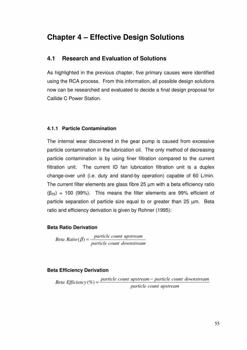
55
Chapter 4 – Effective Design Solutions
4.1 Research and Evaluation of Solutions
As highlighted in the previous chapter, five primary causes were identified
using the RCA process. From this information, all possible design solutions
now can be researched and evaluated to decide a final design proposal for
Callide C Power Station.
4.1.1 Particle Contamination
The internal wear discovered in the gear pump is caused from excessive
particle contamination in the lubrication oil. The only method of decreasing
particle contamination is by using finer filtration compared to the current
filtration unit. The current ID fan lubrication filtration unit is a duplex
change-over unit (i.e. duty and stand-by operation) capable of 60 L/min.
The current filter elements are glass fibre 25 µm with a beta efficiency ratio
(β25) = 100 (99%). This means the filter elements are 99% efficient of
particle separation of particle size equal to or greater than 25 µm. Beta
ratio and efficiency derivation is given by Rohner (1995):
Beta Ratio Derivation
downstreamcountparticle
upstreamcountparticleRatioBeta =)(β
Beta Efficiency Derivation
upstreamcountparticle
downstreamcountparticleupstreamcountparticleEfficiencyBeta
−=(%)
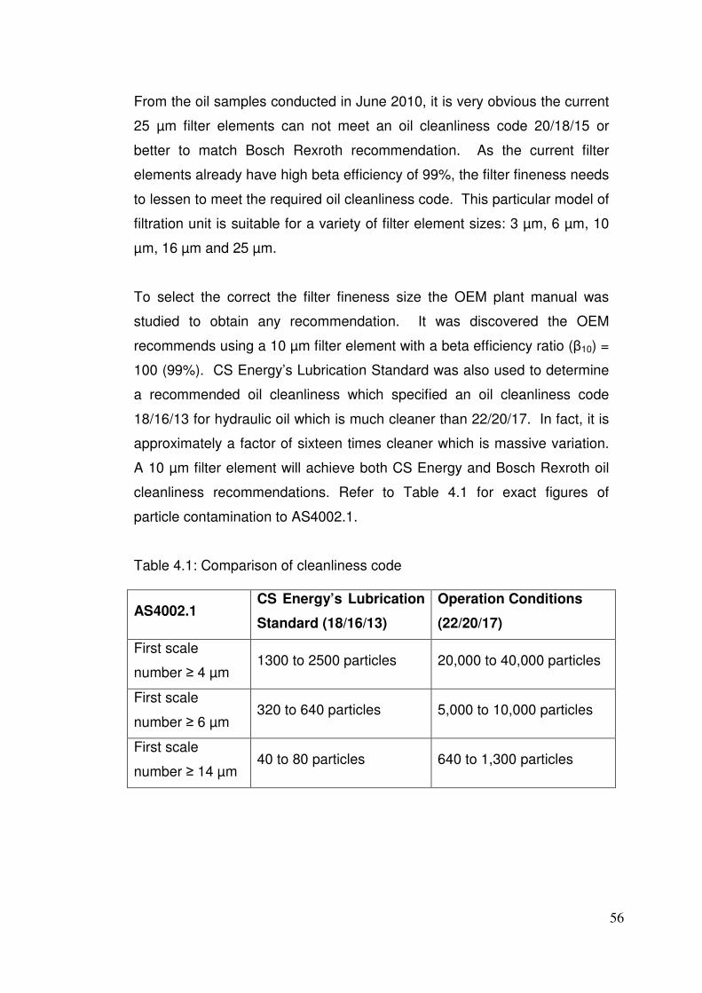
56
From the oil samples conducted in June 2010, it is very obvious the current
25 µm filter elements can not meet an oil cleanliness code 20/18/15 or
better to match Bosch Rexroth recommendation. As the current filter
elements already have high beta efficiency of 99%, the filter fineness needs
to lessen to meet the required oil cleanliness code. This particular model of
filtration unit is suitable for a variety of filter element sizes: 3 µm, 6 µm, 10
µm, 16 µm and 25 µm.
To select the correct the filter fineness size the OEM plant manual was
studied to obtain any recommendation. It was discovered the OEM
recommends using a 10 µm filter element with a beta efficiency ratio (β10) =
100 (99%). CS Energy’s Lubrication Standard was also used to determine
a recommended oil cleanliness which specified an oil cleanliness code
18/16/13 for hydraulic oil which is much cleaner than 22/20/17. In fact, it is
approximately a factor of sixteen times cleaner which is massive variation.
A 10 µm filter element will achieve both CS Energy and Bosch Rexroth oil
cleanliness recommendations. Refer to Table 4.1 for exact figures of
particle contamination to AS4002.1.
Table 4.1: Comparison of cleanliness code
AS4002.1 CS Energy’s Lubrication
Standard (18/16/13)
Operation Conditions
(22/20/17)
First scale
number ≥ 4 µm 1300 to 2500 particles 20,000 to 40,000 particles
First scale
number ≥ 6 µm 320 to 640 particles 5,000 to 10,000 particles
First scale
number ≥ 14 µm 40 to 80 particles 640 to 1,300 particles
57
A 10 µm filter element which will achieve an oil cleanliness code 18/16/13
would dramatically decrease gear pump internal wear and therefore
improve long-term reliability. To change from 25 to 10 µm filter element
only requires a change to the material specification which is a very simple
change at minimal cost.
4.1.2 Internal Tank Design
The ID fan lubrication tank is suffering from poor internal tank design which
permits air to enter the stand-by pump suction line and causing inability of
pump to prime. Neale (1995, p.C20.1 – 20.2) has a section of his book
“The Tribology Handbook” which shows correct design of lubrication
storage tanks. There are four key aspects for correct internal tank design
to prevent air entering pump suction line:
• Return line
• Suction line
• Baffles and weirs
• De-aeration screen
Return Line
As shown in Figure 3.9, the tank return lines have 90° elbows and DN50
mm vertical straight sections which direct oil flow downwards at one-third
tank level. This allows air entrained oil to circulate directly into pump
suction line before the air has been separated from the oil. Neale (1995,
p.C20.1) recommendations for tank return lines:
� Location: at or just above running level
� Size and slope: chosen to run less than half full to let foam drain,
and with least velocity to avoid turbulence.
� Refinement: perforated tray at exit point prevents aeration due to
plunging
58
If the two 90° elbows and straight sections were removed from the tank
internals, the return line design would be at the correct location, size and
slope. This would prevent air entrained oil to circulate directly into pump
suction line and is a straightforward modification. A perforated tray could
be easily installed for further refinement if deemed necessary.
Suction Line
The pump suction lines currently have a 130 µm stainless steel strainer
located at the bottom of the tank. A suction strainer is a coarse filter used
to prevent large foreign particles entering the pump that would cause
catastrophic failure. Neale (1995, p.C20.1) recommendations for tank
suction lines:
� Location: remote from return line
� Inlet depth: between tank bottom and one-third of running level
� Refinement: foot-valve suction strainer to maintain fluid in pump and
prevent air entering pump
The current suction line location and inlet depth is adequate as per
recommended design. However the suction strainers do not have a built-in
foot valve. The installation of a foot valve suction strainer is simple and
inexpensive. However pressure losses through the foot valve must be
carefully considered to avoid insufficient suction pressure to pump which
may cause cavitation and/or inability to prime.
59
Baffle and Weirs
The current internal tank design does not have baffles and weirs. Baffles
and weirs serve three primary purposes: (1) provide structural stiffening of
tank walls, (2) inhibit sloshing in mobile systems and (3) prevent direct flow
between return and suction (Neale 1995, p.C20.1). As the ID fan tank
system does not require additional stiffening or reduced sloshing, the
addition of baffles and weirs would only be applicable to prevent direct flow
between return and suction. To install a series of baffles in the existing
lubrication tank design will be very difficult and expensive due to tank
configuration and large amount of workshop work required.
De-aeration Screen
The existing internal tank design does not have a de-aeration screen for the
removal of entrained air in oil. De-aeration screens are typically 100 mesh
(150 µm) and there sole purpose is to separate air from oil to prevent
recirculation of air entrained oil (Neale 1995, p.C20.2). Correct design is to
completely immerse the screen as surface foam can penetrate the finest
screen.
The installation of a suitable de-aeration screen into the current tank design
would require site dimensions, design drafting, fabrication and installation.
Careful thought into the design is required so it can be installed without
using welding and/or flame cutting to minimise cost and installation time.
The design must be simple enough so all fabrication is done in a workshop
and the only site installation work required is loosen/tighten of mechanical
fasteners.
60
4.1.3 Simplify System Design
The existing throttle valves and adjustable orifices in the ID fan lubrication
system are over-complicating the oil flow rate set-up process. Too simplify
lubrication design and set-up process, many lubrication systems are
designed with fixed-size orifices. The cross-sectional area of a fixed-size
orifice is calculated so correct flow rate and constant system pressure is
maintained. This avoids any human intervention which can lead to in-
correct set-up during commissioning and on-going maintenance.
If the two adjustable orifices at the inlet to the induction motor bearings
were replaced with precisely machined fixed-size orifices, the two throttle
valves could be removed or made redundant and only used for fine tuning
system flow rates. The cross-sectional area of the fixed-size orifices will
need to be calculated so flow rate to induction motor DE and NDE bearings
is 10 L/min and 5 L/min respectively. The remaining system flow rate will
be directed to the fan main shaft bearings.
To minimise cost and simplify installation of fixed-size orifices, the design
must permit the external dimensions of existing adjustable orifice.
Therefore no pipe work modification will be required and site installation is
straightforward.
61
4.1.4 Suitable Flow Transmitters
As a result of the Hedland Flow Transmitters removed from service in 2004,
the flow rates to the induction motor bearings and fan main shaft bearings
have been unknown. This poses a huge risk to in-correct system set-up
and no flow rate monitoring for machine protection. The only method of
continuously monitoring flow rate in the ID fan lubrication system is to install
good quality and accurate flow transmitters. Thorough research and design
must be considered when selecting suitable flow transmitters to avoid the
failures which plagued the OEM Hedland Flow Transmitters.
There are many different styles and types of flow transmitters available in
today’s industry. Each has their advantages and disadvantages for specific
applications throughout a wide range of industries. The most common
models available are:
• Differential Pressure Flowmeter
• Variable Area Flowmeter
• Positive Displacement Flowmeter
• Turbine Flowmeter
• Vortex Flowmeter
• Electromagnetic Flowmeter
• Ultrasonic Flowmeter
• Coriolis Mass Flowmeter
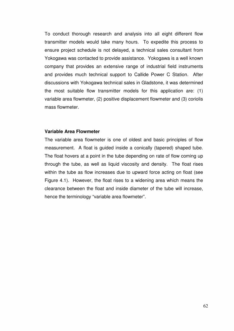
62
To conduct thorough research and analysis into all eight different flow
transmitter models would take many hours. To expedite this process to
ensure project schedule is not delayed, a technical sales consultant from
Yokogawa was contacted to provide assistance. Yokogawa is a well known
company that provides an extensive range of industrial field instruments
and provides much technical support to Callide Power C Station. After
discussions with Yokogawa technical sales in Gladstone, it was determined
the most suitable flow transmitter models for this application are: (1)
variable area flowmeter, (2) positive displacement flowmeter and (3) coriolis
mass flowmeter.
Variable Area Flowmeter
The variable area flowmeter is one of oldest and basic principles of flow
measurement. A float is guided inside a conically (tapered) shaped tube.
The float hovers at a point in the tube depending on rate of flow coming up
through the tube, as well as liquid viscosity and density. The float rises
within the tube as flow increases due to upward force acting on float (see
Figure 4.1). However, the float rises to a widening area which means the
clearance between the float and inside diameter of the tube will increase,
hence the terminology “variable area flowmeter”.

63
Figure 4.1: Variable area measurement principle
Table 4.2 – Advantages and disadvantages of variable area flowmeters
Advantages Disadvantages
• Lowest cost flowmeter.
• 2-wire loop powered transmitter,
so no external power required.
• Simple and reliable construction.
• Suitable for slightly dirty liquids.
• Suitable for pressures up to 200
bar and temperatures up to
400°C.
• Simple on-going maintenance.
• Low pressure losses across
flowmeter.
• Accuracy between 1 – 2% of full
scale reading.
• Flowmeter is calibrated to a
predetermined liquid viscosity
and density, so any change will
affect flowmeter accuracy.
• Not suitable for high viscosity
liquids.
• Liquid can not contain large
concentration of solids.
• Must be installed in vertical
position with liquid flowing
upwards.
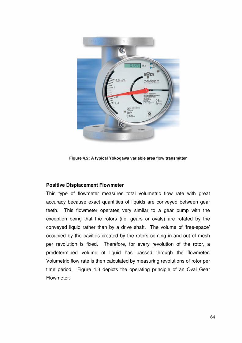
64
Figure 4.2: A typical Yokogawa variable area flow transmitter
Positive Displacement Flowmeter
This type of flowmeter measures total volumetric flow rate with great
accuracy because exact quantities of liquids are conveyed between gear
teeth. This flowmeter operates very similar to a gear pump with the
exception being that the rotors (i.e. gears or ovals) are rotated by the
conveyed liquid rather than by a drive shaft. The volume of ‘free-space’
occupied by the cavities created by the rotors coming in-and-out of mesh
per revolution is fixed. Therefore, for every revolution of the rotor, a
predetermined volume of liquid has passed through the flowmeter.
Volumetric flow rate is then calculated by measuring revolutions of rotor per
time period. Figure 4.3 depicts the operating principle of an Oval Gear
Flowmeter.
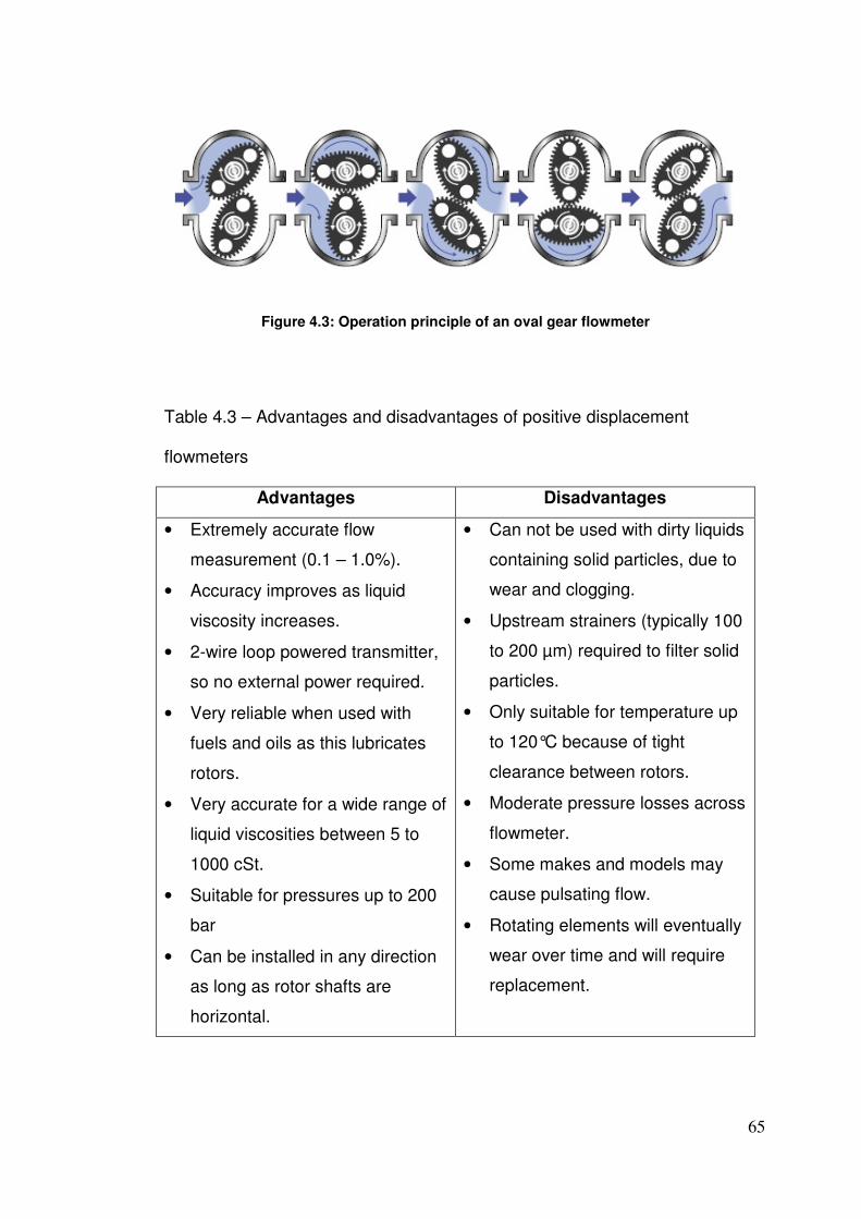
65
Figure 4.3: Operation principle of an oval gear flowmeter
Table 4.3 – Advantages and disadvantages of positive displacement
flowmeters
Advantages Disadvantages
• Extremely accurate flow
measurement (0.1 – 1.0%).
• Accuracy improves as liquid
viscosity increases.
• 2-wire loop powered transmitter,
so no external power required.
• Very reliable when used with
fuels and oils as this lubricates
rotors.
• Very accurate for a wide range of
liquid viscosities between 5 to
1000 cSt.
• Suitable for pressures up to 200
bar
• Can be installed in any direction
as long as rotor shafts are
horizontal.
• Can not be used with dirty liquids
containing solid particles, due to
wear and clogging.
• Upstream strainers (typically 100
to 200 µm) required to filter solid
particles.
• Only suitable for temperature up
to 120°C because of tight
clearance between rotors.
• Moderate pressure losses across
flowmeter.
• Some makes and models may
cause pulsating flow.
• Rotating elements will eventually
wear over time and will require
replacement.
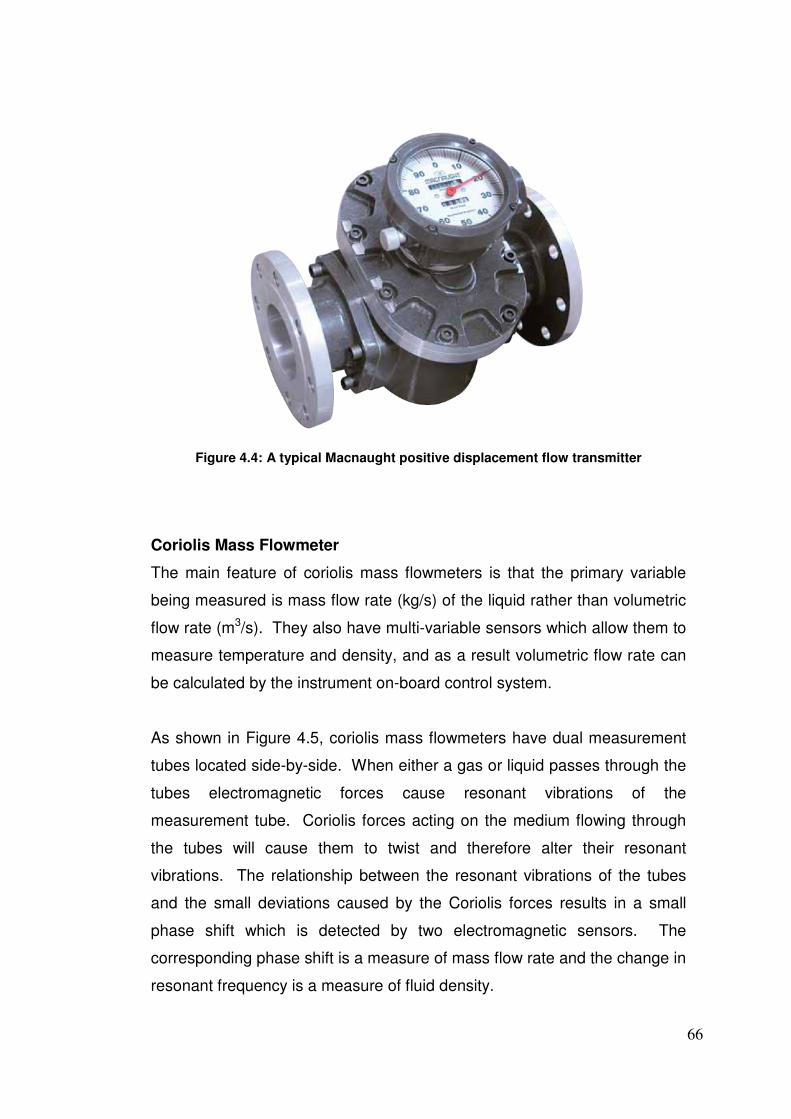
66
Figure 4.4: A typical Macnaught positive displacement flow transmitter
Coriolis Mass Flowmeter
The main feature of coriolis mass flowmeters is that the primary variable
being measured is mass flow rate (kg/s) of the liquid rather than volumetric
flow rate (m3/s). They also have multi-variable sensors which allow them to
measure temperature and density, and as a result volumetric flow rate can
be calculated by the instrument on-board control system.
As shown in Figure 4.5, coriolis mass flowmeters have dual measurement
tubes located side-by-side. When either a gas or liquid passes through the
tubes electromagnetic forces cause resonant vibrations of the
measurement tube. Coriolis forces acting on the medium flowing through
the tubes will cause them to twist and therefore alter their resonant
vibrations. The relationship between the resonant vibrations of the tubes
and the small deviations caused by the Coriolis forces results in a small
phase shift which is detected by two electromagnetic sensors. The
corresponding phase shift is a measure of mass flow rate and the change in
resonant frequency is a measure of fluid density.
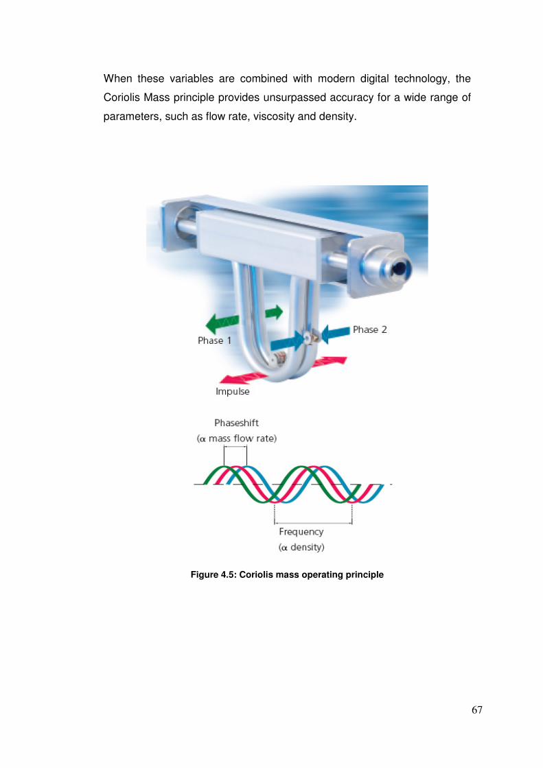
67
When these variables are combined with modern digital technology, the
Coriolis Mass principle provides unsurpassed accuracy for a wide range of
parameters, such as flow rate, viscosity and density.
Figure 4.5: Coriolis mass operating principle
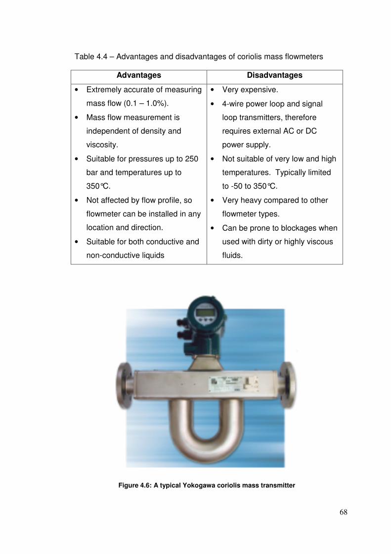
68
Table 4.4 – Advantages and disadvantages of coriolis mass flowmeters
Advantages Disadvantages
• Extremely accurate of measuring
mass flow (0.1 – 1.0%).
• Mass flow measurement is
independent of density and
viscosity.
• Suitable for pressures up to 250
bar and temperatures up to
350°C.
• Not affected by flow profile, so
flowmeter can be installed in any
location and direction.
• Suitable for both conductive and
non-conductive liquids
• Very expensive.
• 4-wire power loop and signal
loop transmitters, therefore
requires external AC or DC
power supply.
• Not suitable of very low and high
temperatures. Typically limited
to -50 to 350°C.
• Very heavy compared to other
flowmeter types.
• Can be prone to blockages when
used with dirty or highly viscous
fluids.
Figure 4.6: A typical Yokogawa coriolis mass transmitter
69
4.1.5 Pressure Alarm and Trip Values
Due to in-correct pressure alarm and trip values which did not allow for
fluctuating oil viscosity and system pressure, the Callide C ID fans were
always going to cause operational issues, especially on hot summer days.
There are two options which can be considered to correct this problem: (1)
disable the alarm and trip values from the ICMS, or (2) use fluid mechanic
equations to calculate correct values.
Disabling the pressure alarm and trip values from the ICMS would be a
feasible idea only if accurate flow transmitters were to be reinstated with a
back-up transmitter on each line for emergency redundancy. Currently, the
only form of lubrication system monitoring is via the pressure transmitters
and if this protection is removed, the last form of protection for the ID fans is
bearing metal temperature. Having bearing metal temperature as the only
form of equipment protection poses increased risk to the future reliability of
the ID fans. Bearing metal temperature protection should only be the last
form of protection to avoid major equipment failure and associated costs.
However, the other alternative of using fluid mechanic equations to
calculate correct protection values can be easily achieved and implemented
into the ICMS. The values will need to be calculated using “worst case
scenario” parameters to account for maximum oil temperature and
minimum system pressures.
70
Chapter 5 – Modification Design Proposal
5.1 Design Considerations
As discussed in Chapter 4, there is a wide variety of possible solutions for
the Callide C ID fan lubrication systems. However carefully consideration
must be sought when deciding which solutions are best to incorporate into
the final design proposal. The key factors which must be considered are:
• Initial capital and on-going maintenance cost
• Simple and user-friendly design for future maintenance
• Easy installation methodology to minimise possible errors
• Do not introduce potential failure modes into the system
5.1.1 Filter Element Selection
To ensure lubrication oil cleanliness code is 20/18/15 or better, the only
viable solution is to replace the existing filter elements from 25 to 10µm.
This solution is very easy and inexpensive. Once all filters across all four
ID fans have been replaced, the CS Energy stock material specification will
require updating to incorporate the difference in filter fineness.
5.1.2 Internal Tank Modifications
As highlighted in Chapter 4, the internal tank design of the ID fan lubrication
system suffers from incorrect design which is allowing air entrained oil to
enter the pump suction strainer. The easiest and most cost effective way to
correct this solution is to remove the two 90° elbows and DN50 mm pipe
straight sections from the tank internals. This will require removing the tank
lid via loosening the fasteners and cutting the pipe section at the tank
running level.
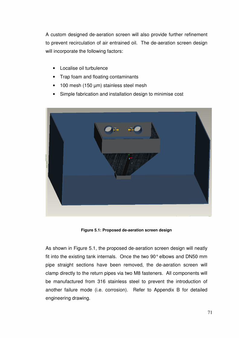
71
A custom designed de-aeration screen will also provide further refinement
to prevent recirculation of air entrained oil. The de-aeration screen design
will incorporate the following factors:
• Localise oil turbulence
• Trap foam and floating contaminants
• 100 mesh (150 µm) stainless steel mesh
• Simple fabrication and installation design to minimise cost
Figure 5.1: Proposed de-aeration screen design
As shown in Figure 5.1, the proposed de-aeration screen design will neatly
fit into the existing tank internals. Once the two 90° elbows and DN50 mm
pipe straight sections have been removed, the de-aeration screen will
clamp directly to the return pipes via two M8 fasteners. All components will
be manufactured from 316 stainless steel to prevent the introduction of
another failure mode (i.e. corrosion). Refer to Appendix B for detailed
engineering drawing.
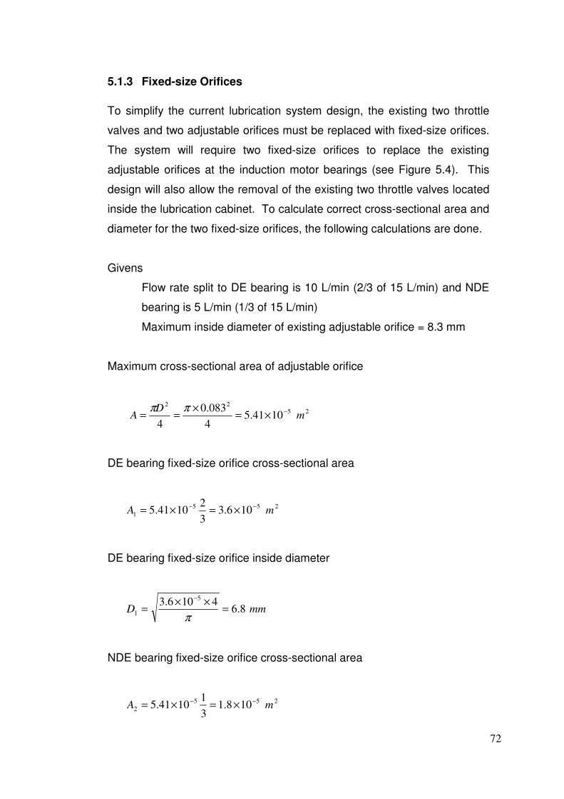
72
5.1.3 Fixed-size Orifices
To simplify the current lubrication system design, the existing two throttle
valves and two adjustable orifices must be replaced with fixed-size orifices.
The system will require two fixed-size orifices to replace the existing
adjustable orifices at the induction motor bearings (see Figure 5.4). This
design will also allow the removal of the existing two throttle valves located
inside the lubrication cabinet. To calculate correct cross-sectional area and
diameter for the two fixed-size orifices, the following calculations are done.
Givens
Flow rate split to DE bearing is 10 L/min (2/3 of 15 L/min) and NDE
bearing is 5 L/min (1/3 of 15 L/min)
Maximum inside diameter of existing adjustable orifice = 8.3 mm
Maximum cross-sectional area of adjustable orifice
2522
1041.54
083.0
4m
DA
−×=×
==ππ
DE bearing fixed-size orifice cross-sectional area
255
1 106.33
21041.5 mA
−− ×=×=
DE bearing fixed-size orifice inside diameter
mmD 8.64106.3
5
1 =××
=−
π
NDE bearing fixed-size orifice cross-sectional area
255
2 108.13
11041.5 mA
−− ×=×=

73
NDE bearing fixed-size orifice inside diameter
mmD 8.44108.1
5
2 =××
=−
π
This process gives D1 = 6.8 mm and D2 = 4.8 mm for the inside diameter of
two fixed-size orifices. This will ensure a 2/3:1/3 ratio split of flow rate into
the induction motor bearings at all times. The above calculations are based
on existing adjustable orifice maximum diameter 8.3 mm to minimise
pressure losses and additional heat. Refer to Appendix B for detailed
engineering drawing of fixed-size orifices.
Note: When commissioning the lubrication system with the fixed-size
orifices, the flow rates to the fan main shaft bearings and induction motors
bearings must be confirmed to be within OEM specifications. If the flow
rates are not correct, the above calculations must be repeated using
smaller or larger orifice diameters. If the flow rate to induction motor
bearings is too high, then fixed-size orifice diameter is to be reduced and
vice-versa if flow rate is too low. A Matlab program (see Figure 5.3) has
been developed to simplify this process and ensure 2/3:1/3 ratio split is
always maintained.
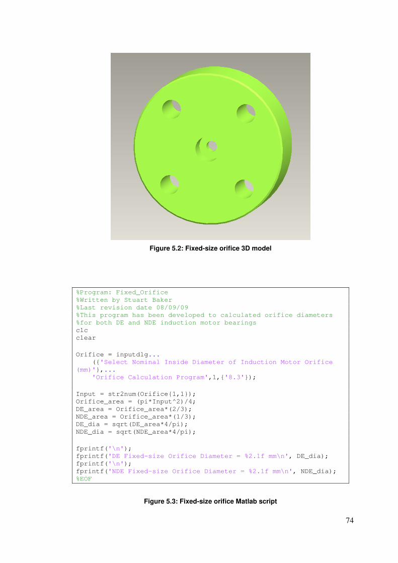
74
Figure 5.2: Fixed-size orifice 3D model
%Program: Fixed_Orifice %Written by Stuart Baker %Last revision date 08/09/09 %This program has been developed to calculated orifice diameters %for both DE and NDE induction motor bearings clc clear
Orifice = inputdlg... ({'Select Nominal Inside Diameter of Induction Motor Orifice
(mm)'},... 'Orifice Calculation Program',1,{'8.3'});
Input = str2num(Orifice{1,1}); Orifice_area = (pi*Input^2)/4; DE_area = Orifice_area*(2/3); NDE_area = Orifice_area*(1/3); DE_dia = sqrt(DE_area*4/pi); NDE_dia = sqrt(NDE_area*4/pi);
fprintf('\n'); fprintf('DE Fixed-size Orifice Diameter = %2.1f mm\n', DE_dia); fprintf('\n'); fprintf('NDE Fixed-size Orifice Diameter = %2.1f mm\n', NDE_dia); %EOF
Figure 5.3: Fixed-size orifice Matlab script
75
5.1.4 Accurate Flow Transmitters
The previous research conducted on suitable flow transmitters for the ID
fan lubrication system highlighted two possible alternatives: (1) positive
displacement flow transmitter and (2) coriolis mass transmitter. Both
models offer excellent accuracy with varying oil viscosity, density and
pressure. The decision of which model to choose will come down to
purchase and installation cost.
The approximate cost of a suitable positive displacement flow transmitter
for this particular application is $2,500. Whereas, the approximate cost of a
suitable coriolis mass transmitter is much greater at $10,000. The coriolis
mass flow transmitter will also require an external power source as it is a 4-
wire configuration. Providing an external AC/DC power source will
dramatically increase installation cost. However, the positive displacement
flow transmitter is a 2-wire configuration and does not require an external
power source. Given this information, the positive displacement flow
transmitter is the most cost effective and reliable model for the ID fan
lubrication system.
After discussion with Yokogawa technical sales in Gladstone, it was
confirmed the best suited positive displacement flow transmitter for this
application is a Macnaught M4 – ½” pulse and LC display flow meter, refer
to Appendix C for specifications. This particular model is ideal for this
application because:
• Compact size and easy installation
• Can be mounted horizontal or vertical
• Low pressure drop (15 to 20 kPa) across flow meter allows for
economical pump performance and negligible additional heat
• Flow meter accuracy is ±0.5%
• Basic design to minimise the number of wearable and replacement
parts
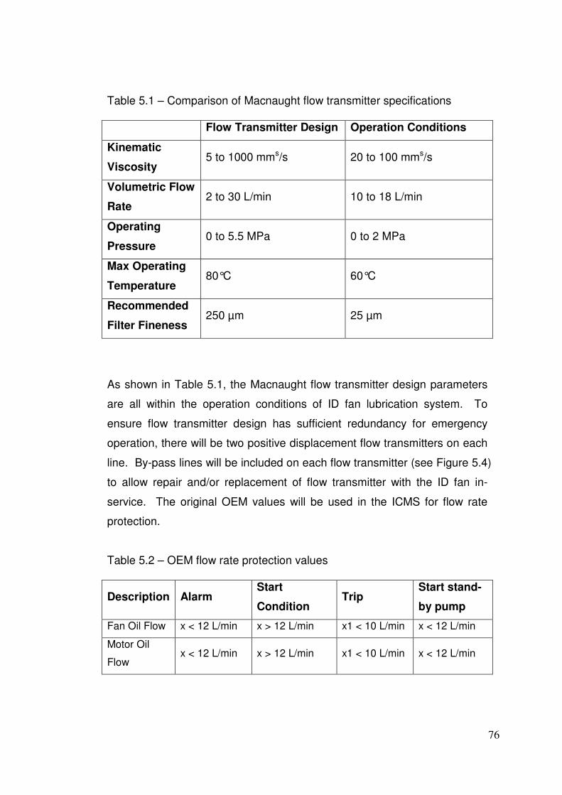
76
Table 5.1 – Comparison of Macnaught flow transmitter specifications
Flow Transmitter Design Operation Conditions
Kinematic
Viscosity 5 to 1000 mms/s 20 to 100 mms/s
Volumetric Flow
Rate 2 to 30 L/min 10 to 18 L/min
Operating
Pressure 0 to 5.5 MPa 0 to 2 MPa
Max Operating
Temperature 80°C 60°C
Recommended
Filter Fineness 250 µm 25 µm
As shown in Table 5.1, the Macnaught flow transmitter design parameters
are all within the operation conditions of ID fan lubrication system. To
ensure flow transmitter design has sufficient redundancy for emergency
operation, there will be two positive displacement flow transmitters on each
line. By-pass lines will be included on each flow transmitter (see Figure 5.4)
to allow repair and/or replacement of flow transmitter with the ID fan in-
service. The original OEM values will be used in the ICMS for flow rate
protection.
Table 5.2 – OEM flow rate protection values
Description Alarm Start
Condition Trip
Start stand-
by pump
Fan Oil Flow x < 12 L/min x > 12 L/min x1 < 10 L/min x < 12 L/min
Motor Oil
Flow x < 12 L/min x > 12 L/min x1 < 10 L/min x < 12 L/min
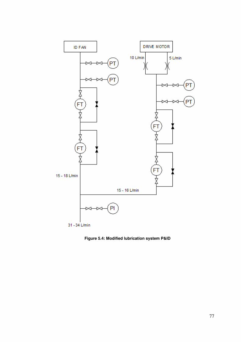
77
Figure 5.4: Modified lubrication system P&ID
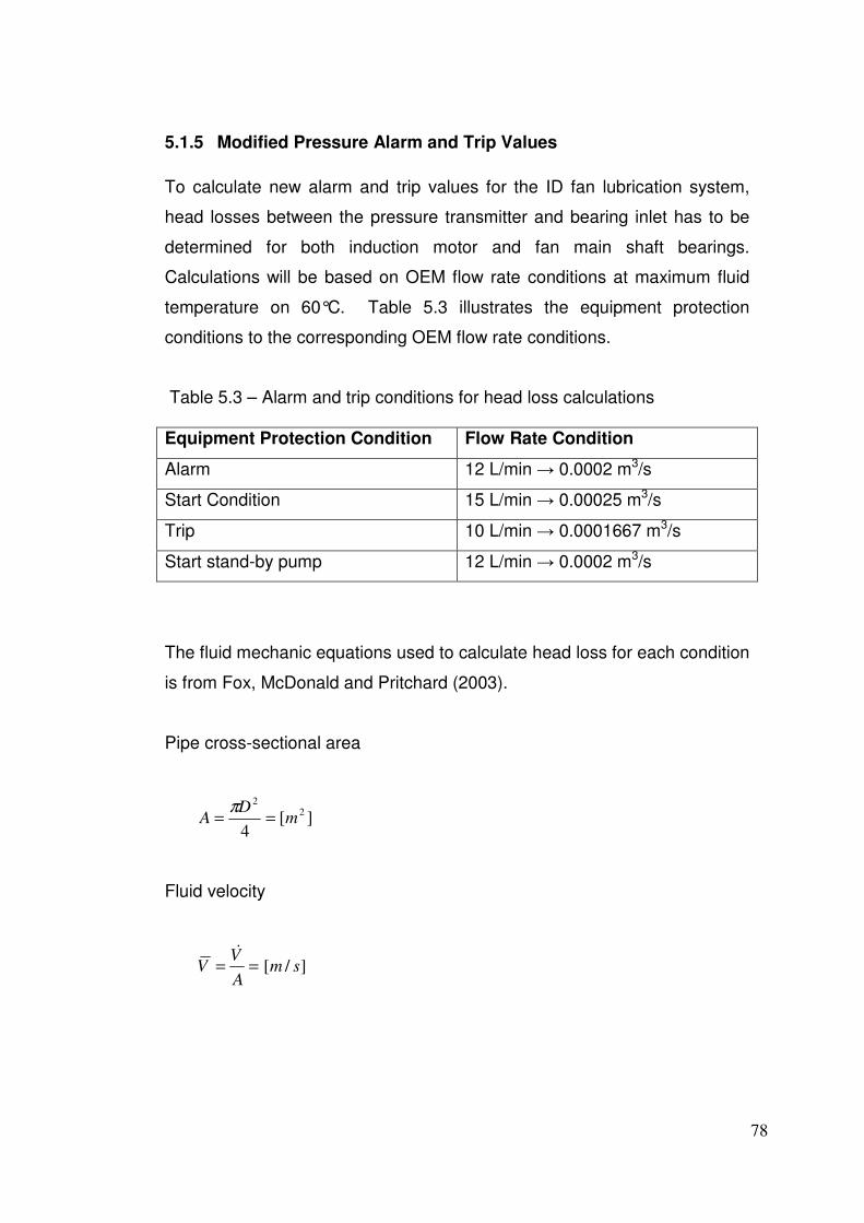
78
5.1.5 Modified Pressure Alarm and Trip Values
To calculate new alarm and trip values for the ID fan lubrication system,
head losses between the pressure transmitter and bearing inlet has to be
determined for both induction motor and fan main shaft bearings.
Calculations will be based on OEM flow rate conditions at maximum fluid
temperature on 60°C. Table 5.3 illustrates the equipment protection
conditions to the corresponding OEM flow rate conditions.
Table 5.3 – Alarm and trip conditions for head loss calculations
Equipment Protection Condition Flow Rate Condition
Alarm 12 L/min → 0.0002 m3/s
Start Condition 15 L/min → 0.00025 m3/s
Trip 10 L/min → 0.0001667 m3/s
Start stand-by pump 12 L/min → 0.0002 m3/s
The fluid mechanic equations used to calculate head loss for each condition
is from Fox, McDonald and Pritchard (2003).
Pipe cross-sectional area
][4
2
2
mD
A ==π
Fluid velocity
]/[ smA
VV ==
&
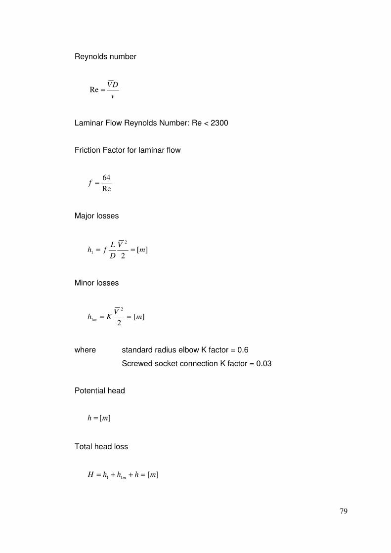
79
Reynolds number
v
DV=Re
Laminar Flow Reynolds Number: Re < 2300
Friction Factor for laminar flow
Re
64=f
Major losses
][2
2
1 mV
D
Lfh ==
Minor losses
][2
2
1 mV
Kh m ==
where standard radius elbow K factor = 0.6
Screwed socket connection K factor = 0.03
Potential head
][mh =
Total head loss
][11 mhhhH m =++=
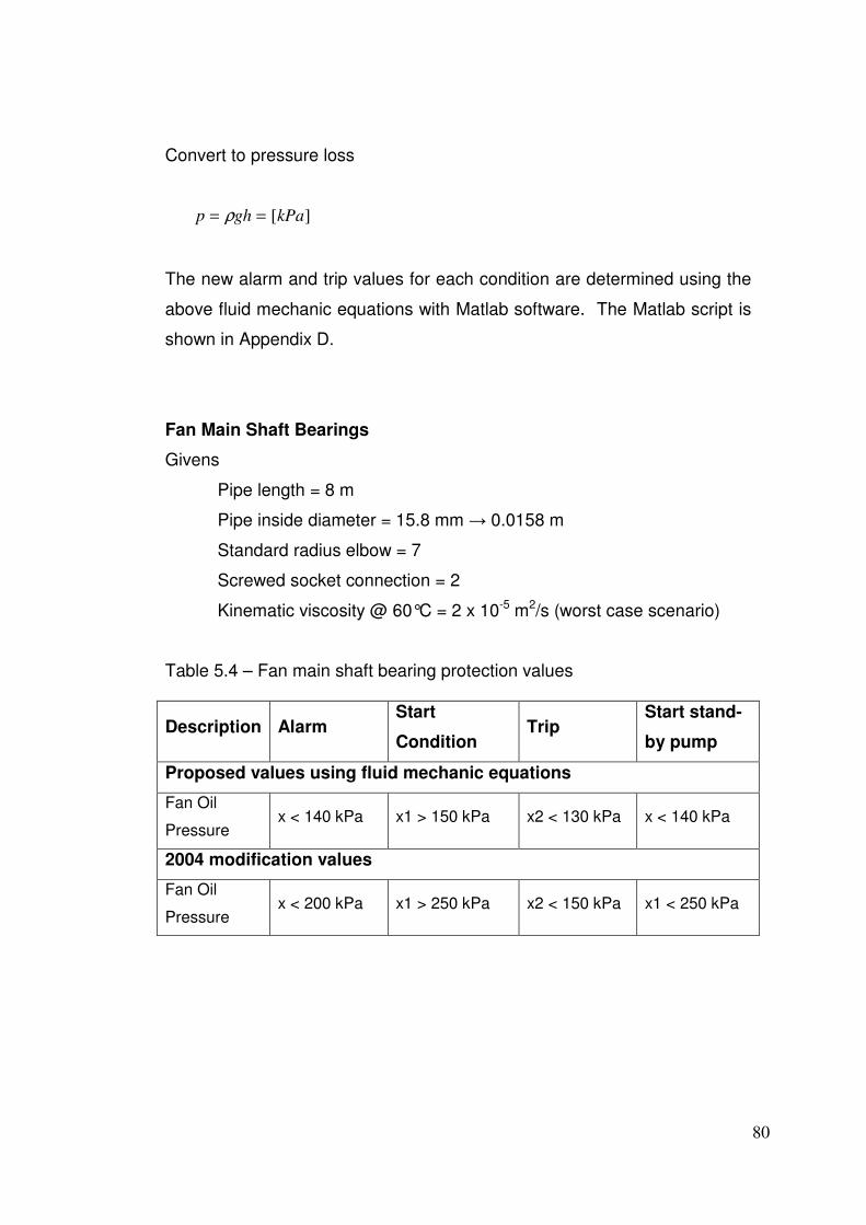
80
Convert to pressure loss
][kPaghp == ρ
The new alarm and trip values for each condition are determined using the
above fluid mechanic equations with Matlab software. The Matlab script is
shown in Appendix D.
Fan Main Shaft Bearings
Givens
Pipe length = 8 m
Pipe inside diameter = 15.8 mm → 0.0158 m
Standard radius elbow = 7
Screwed socket connection = 2
Kinematic viscosity @ 60°C = 2 x 10⁻⁵ m2/s (worst case scenario)
Table 5.4 – Fan main shaft bearing protection values
Description Alarm Start
Condition Trip
Start stand-
by pump
Proposed values using fluid mechanic equations
Fan Oil
Pressure x < 140 kPa x1 > 150 kPa x2 < 130 kPa x < 140 kPa
2004 modification values
Fan Oil
Pressure x < 200 kPa x1 > 250 kPa x2 < 150 kPa x1 < 250 kPa
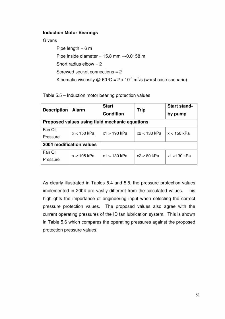
81
Induction Motor Bearings
Givens
Pipe length = 6 m
Pipe inside diameter = 15.8 mm →0.0158 m
Short radius elbow = 2
Screwed socket connections = 2
Kinematic viscosity @ 60°C = 2 x 10⁻⁵ m2/s (worst case scenario)
Table 5.5 – Induction motor bearing protection values
Description Alarm Start
Condition Trip
Start stand-
by pump
Proposed values using fluid mechanic equations
Fan Oil
Pressure x < 150 kPa x1 > 190 kPa x2 < 130 kPa x < 150 kPa
2004 modification values
Fan Oil
Pressure x < 105 kPa x1 > 130 kPa x2 < 80 kPa x1 <130 kPa
As clearly illustrated in Tables 5.4 and 5.5, the pressure protection values
implemented in 2004 are vastly different from the calculated values. This
highlights the importance of engineering input when selecting the correct
pressure protection values. The proposed values also agree with the
current operating pressures of the ID fan lubrication system. This is shown
in Table 5.6 which compares the operating pressures against the proposed
protection pressure values.
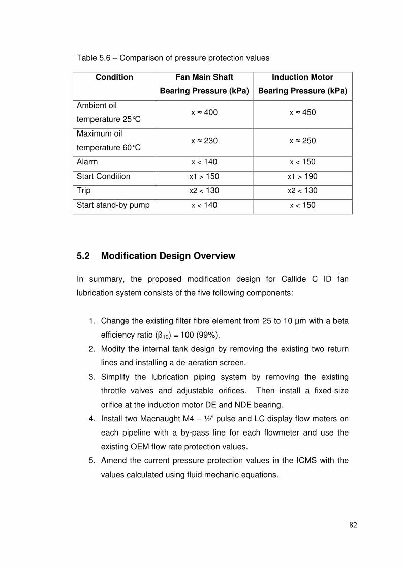
82
Table 5.6 – Comparison of pressure protection values
Condition Fan Main Shaft
Bearing Pressure (kPa)
Induction Motor
Bearing Pressure (kPa)
Ambient oil
temperature 25°C x ≈ 400 x ≈ 450
Maximum oil
temperature 60°C x ≈ 230 x ≈ 250
Alarm x < 140 x < 150
Start Condition x1 > 150 x1 > 190
Trip x2 < 130 x2 < 130
Start stand-by pump x < 140 x < 150
5.2 Modification Design Overview
In summary, the proposed modification design for Callide C ID fan
lubrication system consists of the five following components:
1. Change the existing filter fibre element from 25 to 10 µm with a beta
efficiency ratio (β10) = 100 (99%).
2. Modify the internal tank design by removing the existing two return
lines and installing a de-aeration screen.
3. Simplify the lubrication piping system by removing the existing
throttle valves and adjustable orifices. Then install a fixed-size
orifice at the induction motor DE and NDE bearing.
4. Install two Macnaught M4 – ½” pulse and LC display flow meters on
each pipeline with a by-pass line for each flowmeter and use the
existing OEM flow rate protection values.
5. Amend the current pressure protection values in the ICMS with the
values calculated using fluid mechanic equations.
83
Chapter 6 – Conclusion
6.1 Project Outcomes
The first part of this project was to conduct an engineering appraisal on the
operational and reliability issues in the existing Callide C Power Station ID
fan lubrication system. This appraisal highlighted the importance of proper
bearing and lubrication selection in heavy rotating equipment. It also
showed that the current ID fan bearing and lubrication selection is correct
for this particular application. However, the design of the lubrication system
is suffering from several failure modes which has plagued the ID fans from
initial commissioning in 2001.
Using the Apollo RCA process, five primary causes and their associated
failure modes were identified. Correct identification of root causes is the
most crucial stage during an RCA because research into all possible design
solutions can be then investigated. This project has highlighted the ability
of RCA as a tool for solving the not-so-obvious re-occurring failures in the
ID fan lubrication system.
The second part of this project was to research and evaluate effective
design solutions. Once all solutions were identified, the advantages and
disadvantages for each solution were researched thoroughly to ensure final
design is both practical and cost effective for CS Energy. As discussed in
Chapter 5, the proposed modification design consists of five components,
all of which play a major role into preventing the current operational and
reliability issues.

84
6.2 Further Work
The main aim of this project is the recommendation of a modification design
for the ID fan lubrication system at Callide C Power Station. The next stage
of implementation, which is outside the scope of this project, will require
further financial justification, planning and installation.
To proceed forward with obtaining capital funds for this project, a “Project
Concept Statement” must be prepared by the technical engineering
department. Once the capital funds are approved, the next step will be to
assign the project to a suitably skilled Project Manager, which will most
likely be a Mechanical Engineer. The responsibility of the Project Manager
will be to arrange procurement of necessary parts and then plan/schedule
the installation using a combination of internal and external resources.
Because the ID fans are required at times for maximum plant availability,
the installation of the modification design can only occur during planned
overhauls.
Once the installation and commissioning of the proposed modification
design is complete, the final stage will be to revise and update the existing
plant and operation manuals, and existing mechanical and electrical
engineering drawings. Spare parts for the Macnaught flow transmitter will
also need to be catalogued as stock items along with the development of
preventive maintenance routines for future overhauls.
85
References
Australian Standard 2001, AS 4002.1 – 2001 Hydraulic Fluid Power –
Particulate Contamination of Systems Part 1: Method for Coding the Level
of Contamination, Standards Australia, Sydney.
Department of Mines and Energy-Electricity in Queensland 2010,
Queensland Government, viewed 24 May 2010,
<http://www.dme.qld.gov.au/Energy/electricity_in_queensland.cfm>.
Finley, W.R & Hodowanec M.M 2001, ‘Sleeve vs anti-friction bearings:
Selection of the optimal bearing for induction motors’, IEEE/PCIC 2001
Conference, pp. 3.
Fox, R.W, McDonald, A.T, Pritchard, P.J 2003, Introduction to Fluid
Mechanics, 6th edn, Wiley, Hoboken.
Gano, D.L 2003, Apollo Root Cause Analysis, 2nd edn, Apollonian,
Washington.
Harnoy, A 2003, Bearing Design in Machinery, Marcel Dekker, New York.
Hoppler, R & Errath, R.A 2007, ‘Motor bearing’, Reprint from Global
Cement Magazine October 2007, pp. 2.
Mobley, R.K 1999, Maintenance Fundamentals, Butterworth-Heinemann,
Woburn.
Neale, M.J 1995, The Tribology Handbook, 2nd edn, Butterworth-
Heinemann, Oxford.

86
Power Technology 2010, Net Resources International, viewed 24 May 2010,
<http://www.power-technology.com/projects/callide-coal/>.
Rayaprolu, K 2009, Boiler for Power and Process, Taylor & Francis Group,
Boca Raton.
Rohner, P 1995, Industrial Hydraulic Control, Wiley, Brisbane.
Shell, 2006, Lubricants Report, Product Data Sheet, viewed 24 May 2010,
<http://www-static.shell.com/static/can-
en/downloads/shell_for_businesses/oils_lubricants/3-09.pdf>.
Szeri, A.Z 1998, Fluid Film Lubrication Theory and Design, Cambridge,
New York.
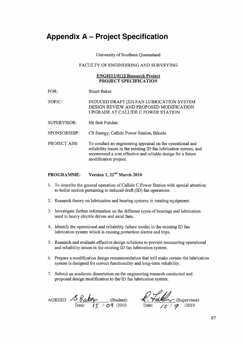
87
Appendix A – Project Specification
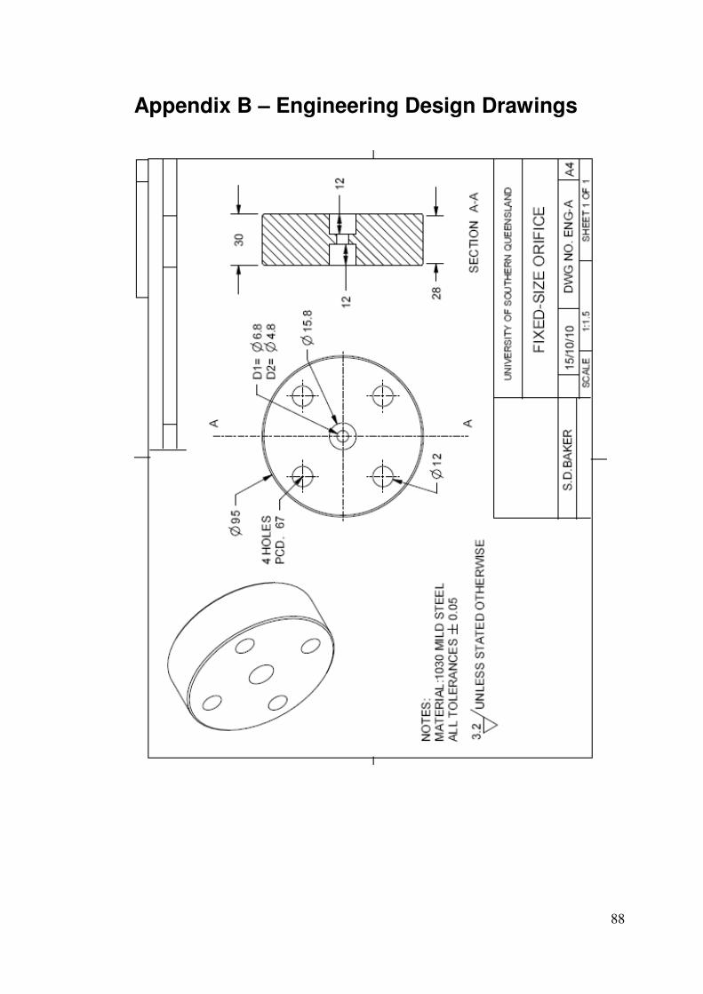
88
Appendix B – Engineering Design Drawings
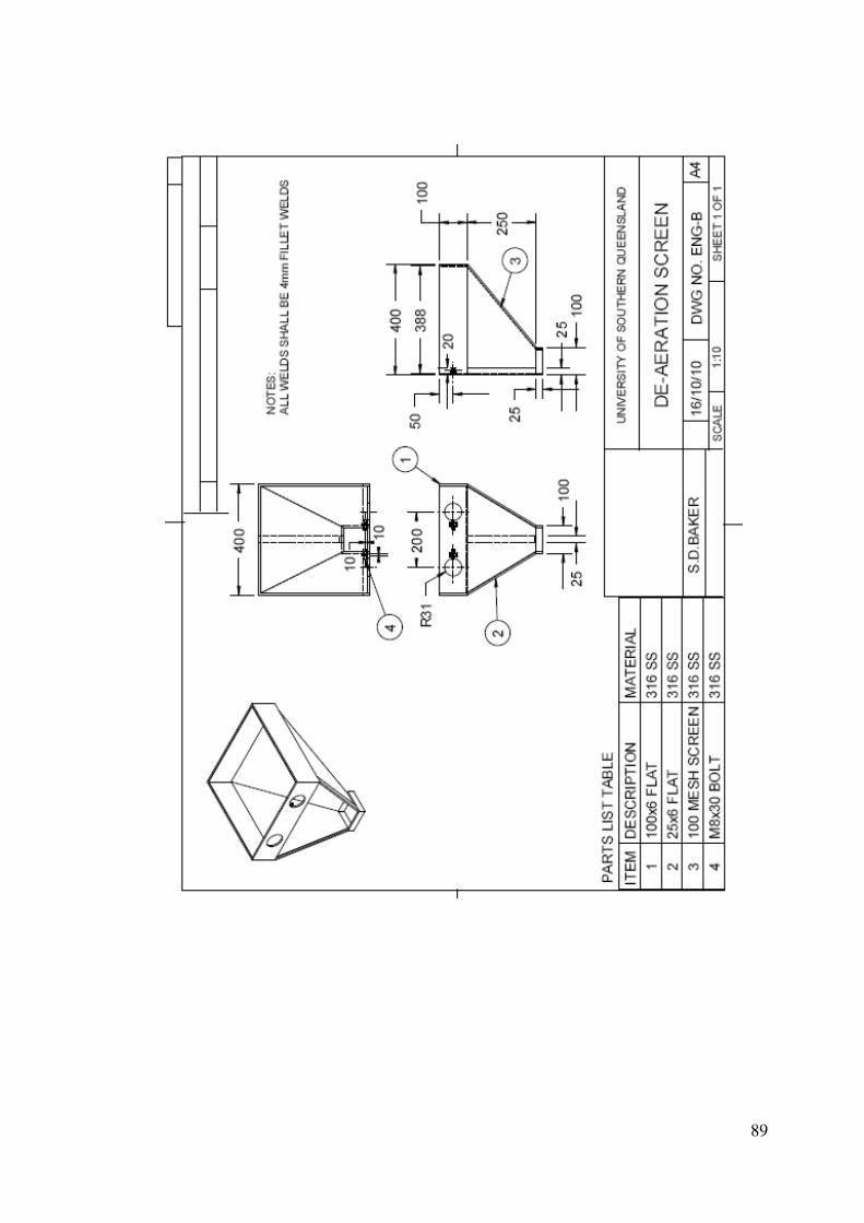
89
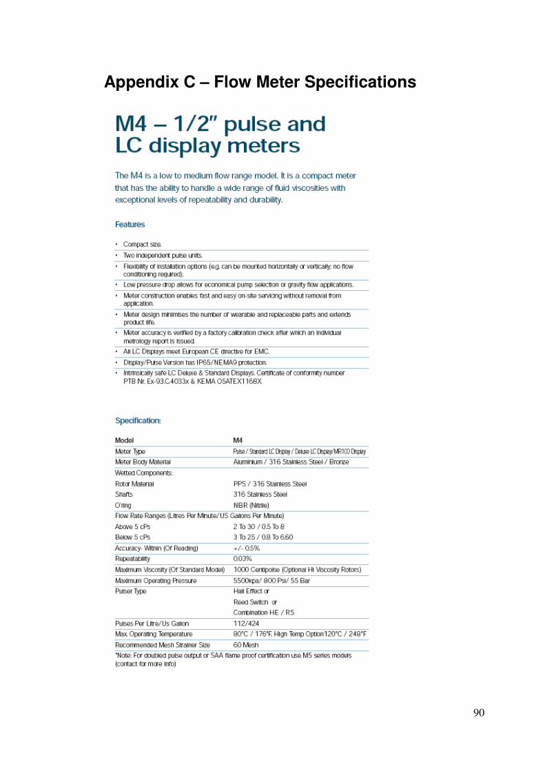
90
Appendix C – Flow Meter Specifications

91

92
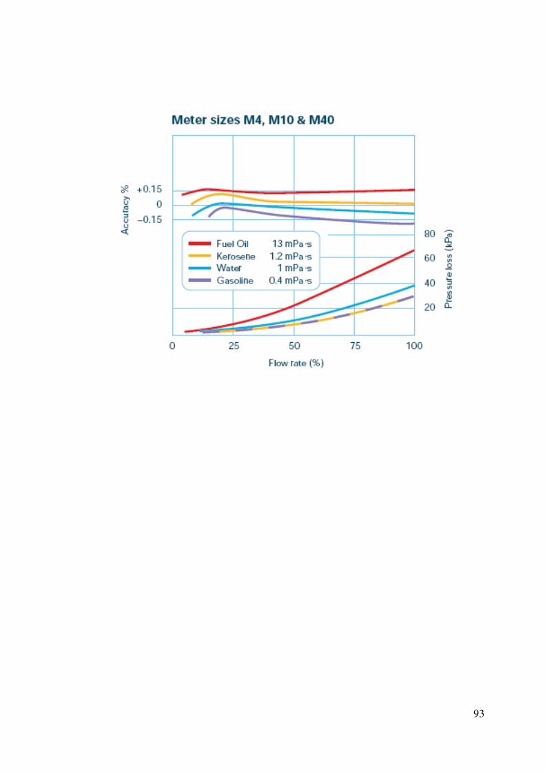
93
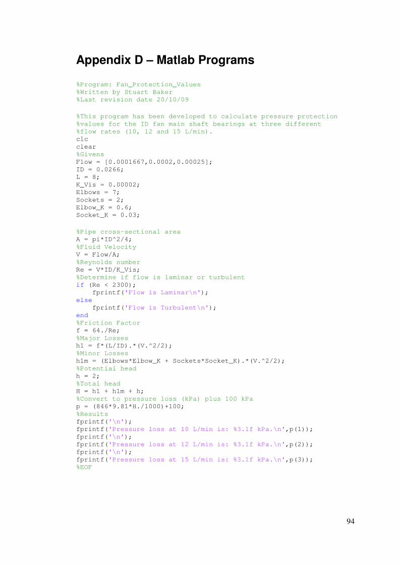
94
Appendix D – Matlab Programs
%Program: Fan_Protection_Values %Written by Stuart Baker %Last revision date 20/10/09
%This program has been developed to calculate pressure protection %values for the ID fan main shaft bearings at three different %flow rates (10, 12 and 15 L/min). clc clear %Givens Flow = [0.0001667,0.0002,0.00025]; ID = 0.0266; L = 8; K_Vis = 0.00002; Elbows = 7; Sockets = 2; Elbow_K = 0.6; Socket_K = 0.03;
%Pipe cross-sectional area A = pi*ID^2/4; %Fluid Velocity V = Flow/A; %Reynolds number Re = V*ID/K_Vis; %Determine if flow is laminar or turbulent if (Re < 2300); fprintf('Flow is Laminar\n'); else fprintf('Flow is Turbulent\n'); end %Friction Factor f = 64./Re; %Major Losses h1 = f*(L/ID).*(V.^2/2); %Minor Losses h1m = (Elbows*Elbow_K + Sockets*Socket_K).*(V.^2/2); %Potential head h = 2; %Total head H = h1 + h1m + h; %Convert to pressure loss (kPa) plus 100 kPa p = (846*9.81*H./1000)+100; %Results fprintf('\n'); fprintf('Pressure loss at 10 L/min is: %3.1f kPa.\n',p(1)); fprintf('\n'); fprintf('Pressure loss at 12 L/min is: %3.1f kPa.\n',p(2)); fprintf('\n'); fprintf('Pressure loss at 15 L/min is: %3.1f kPa.\n',p(3)); %EOF
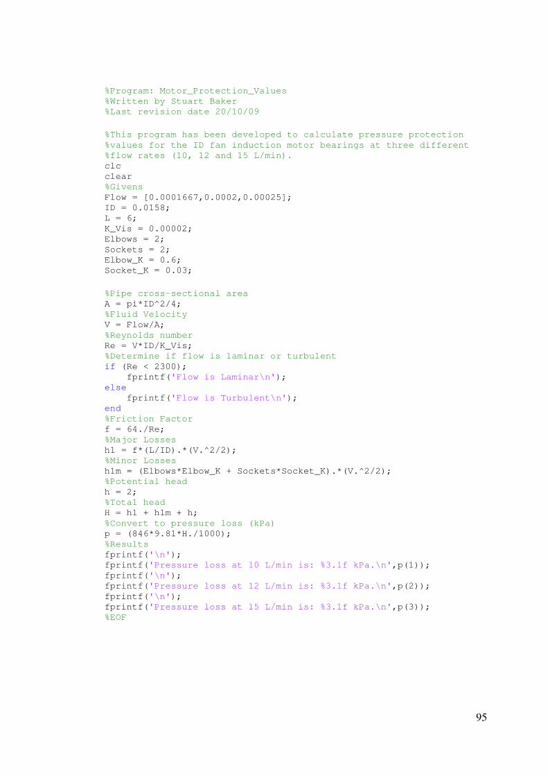
95
%Program: Motor_Protection_Values %Written by Stuart Baker %Last revision date 20/10/09
%This program has been developed to calculate pressure protection %values for the ID fan induction motor bearings at three different %flow rates (10, 12 and 15 L/min). clc clear %Givens Flow = [0.0001667,0.0002,0.00025]; ID = 0.0158; L = 6; K_Vis = 0.00002; Elbows = 2; Sockets = 2; Elbow_K = 0.6; Socket_K = 0.03;
%Pipe cross-sectional area A = pi*ID^2/4; %Fluid Velocity V = Flow/A; %Reynolds number Re = V*ID/K_Vis; %Determine if flow is laminar or turbulent if (Re < 2300); fprintf('Flow is Laminar\n'); else fprintf('Flow is Turbulent\n'); end %Friction Factor f = 64./Re; %Major Losses h1 = f*(L/ID).*(V.^2/2); %Minor Losses h1m = (Elbows*Elbow_K + Sockets*Socket_K).*(V.^2/2); %Potential head h = 2; %Total head H = h1 + h1m + h; %Convert to pressure loss (kPa) p = (846*9.81*H./1000); %Results fprintf('\n'); fprintf('Pressure loss at 10 L/min is: %3.1f kPa.\n',p(1)); fprintf('\n'); fprintf('Pressure loss at 12 L/min is: %3.1f kPa.\n',p(2)); fprintf('\n'); fprintf('Pressure loss at 15 L/min is: %3.1f kPa.\n',p(3)); %EOF