Indoor Unit (IDU)
63
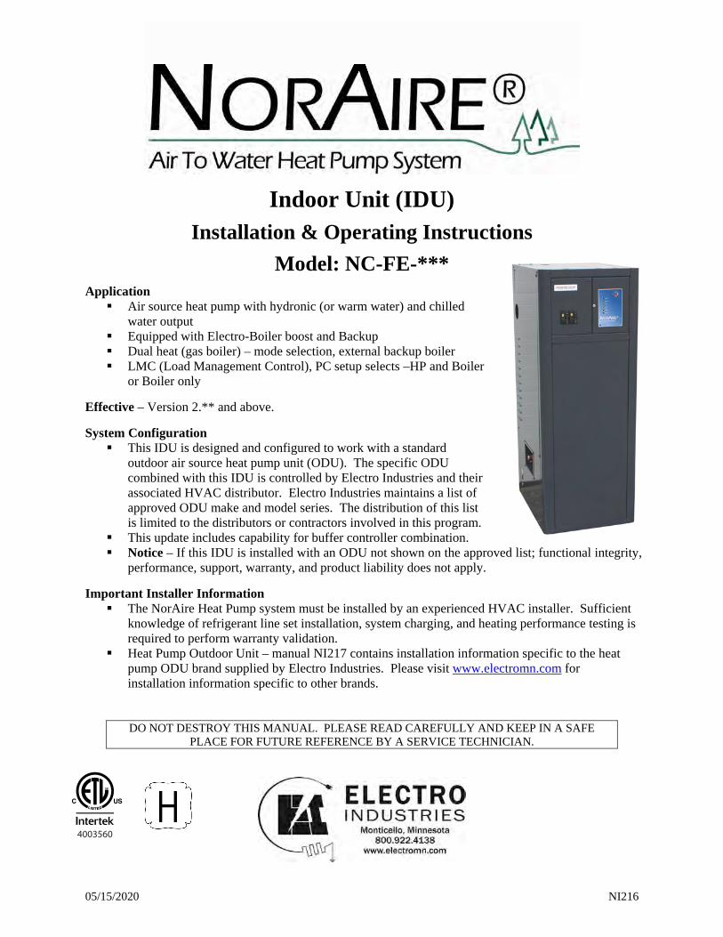
05/15/2020 NI216 Indoor Unit (IDU) Installation & Operating Instructions Model: NC-FE-*** Application Air source heat pump with hydronic (or warm water) and chilled water output Equipped with Electro-Boiler boost and Backup Dual heat (gas boiler) – mode selection, external backup boiler LMC (Load Management Control), PC setup selects –HP and Boiler or Boiler only Effective – Version 2.** and above. System Configuration This IDU is designed and configured to work with a standard outdoor air source heat pump unit (ODU). The specific ODU combined with this IDU is controlled by Electro Industries and their associated HVAC distributor. Electro Industries maintains a list of approved ODU make and model series. The distribution of this list is limited to the distributors or contractors involved in this program. This update includes capability for buffer controller combination. Notice – If this IDU is installed with an ODU not shown on the approved list; functional integrity, performance, support, warranty, and product liability does not apply. Important Installer Information The NorAire Heat Pump system must be installed by an experienced HVAC installer. Sufficient knowledge of refrigerant line set installation, system charging, and heating performance testing is required to perform warranty validation. Heat Pump Outdoor Unit – manual NI217 contains installation information specific to the heat pump ODU brand supplied by Electro Industries. Please visit www.electromn.com for installation information specific to other brands. DO NOT DESTROY THIS MANUAL. PLEASE READ CAREFULLY AND KEEP IN A SAFE PLACE FOR FUTURE REFERENCE BY A SERVICE TECHNICIAN. 4003560
Transcript of Indoor Unit (IDU)
05/15/2020 NI216
Indoor Unit (IDU)
Installation & Operating Instructions
Model: NC-FE-***
Application Air source heat pump with hydronic (or warm water) and chilled
water output Equipped with Electro-Boiler boost and Backup Dual heat (gas boiler) – mode selection, external backup boiler LMC (Load Management Control), PC setup selects –HP and Boiler
or Boiler only
Effective – Version 2.** and above.
System Configuration This IDU is designed and configured to work with a standard
outdoor air source heat pump unit (ODU). The specific ODU combined with this IDU is controlled by Electro Industries and their associated HVAC distributor. Electro Industries maintains a list of approved ODU make and model series. The distribution of this list is limited to the distributors or contractors involved in this program.
This update includes capability for buffer controller combination. Notice – If this IDU is installed with an ODU not shown on the approved list; functional integrity,
performance, support, warranty, and product liability does not apply.
Important Installer Information The NorAire Heat Pump system must be installed by an experienced HVAC installer. Sufficient
knowledge of refrigerant line set installation, system charging, and heating performance testing is required to perform warranty validation.
Heat Pump Outdoor Unit – manual NI217 contains installation information specific to the heat pump ODU brand supplied by Electro Industries. Please visit www.electromn.com for installation information specific to other brands.
DO NOT DESTROY THIS MANUAL. PLEASE READ CAREFULLY AND KEEP IN A SAFE PLACE FOR FUTURE REFERENCE BY A SERVICE TECHNICIAN.
4003560
05/15/2020 NI216
Table of Contents
Introduction 1
Safety Considerations 2
Product Configurator (NC208) 3
Mechanical Specifications 4
Electrical Data 5
Installation Overview, Required System Components 5
Installation Requirements 6
Mechanical Installation
Hydronic – Heating 7
Chilled Water – Cooling 7
Water Fill/Purge Procedure 9
Mechanical Installation – Outdoor Unit (ODU) 14
Electrical Hookup
Power Source 15
Outdoor Unit (ODU) 15
Control 15
Additional Hookup or Special Equipment Concerns 17
Field Setup or Programming 19
Operation Indicators 21
User Instructions 22
Control Sequence 23
Start-Up, Power On 27
Preventative Maintenance 29
Troubleshooting 30
Accessories 34
Replacement Parts 34
Drawings HX103 NH220 NR203
UAW105 XX017 XX036
05/15/2020 1 NI216
Introduction
When used and controlled properly, NorAire heat pumps can save hundreds of dollars in heating and cooling costs per year. NorAire air to water heat pump is designed to provide maximum efficiency, comfort, and reliability. Solid and simple electric controls allow for low maintenance and built in safety protection.
This installation and operating manual covers the indoor unit (IDU) only. As an installed heat pump system this will also include an outdoor unit (ODU) manufactured by others, but used or installed from an approved Electro Industries’ list. This ODU will have its own installation and operating instruction manual supplied by the ODU manufacturer. Also, there may be additional hydronic output items such as buffer tank, hydronic loop circulator pumps, zone valves, zone controller, room thermostat, radiant floor thermostat, chiller water coil, air handler, gas furnace, etc. which will have their own manufacturer installation and operating instructions.
Attached HX103 drawing set provides various suggestions for plumbing and piping. Each page shows a sample heating or cooling possibility, depending upon the complexity of the heating system. On each page the upper left statements attempt to categorize the specific design example. Also, attention needs to be given to the notes pertaining to each page. These can be useful for the designer, installer, and perhaps the user to verify the best and most efficient installation.
It is important the hydronic system be designed and installed according to the building layout, the total heat loss requirement, and proper hydronic installation practices. This NorAire is the energy source for the radiant heat or forced air cooling system, but critical field designed and installed items such as water flow, system component selection, plumbing, and water coil size and airflow will affect performance. The installed NorAire may not necessarily supply the comfort and heat/cool expected.
The operating efficiency of a heat pump product increases as the compressor current decreases. But compressor current increases with outlet supply water temperature increase. Thus, the closer the supply water temperature can be maintained to the true seasonal heating or cooling requirement, the more efficient (less operating cost) the heat pump system will be. Optional or add-on devices with outdoor reset supply water temperature control generally reduce annual operating cost.
Installation Tasks This system requires more than a basic electrical hookup and refrigerant line sets. Attention needs to be given to all installation and troubleshooting sections of this manual starting with page 8 through Start-Up, Power On. Especially the Field Setup or Programming and Additional Special Equipment Concerns could be unique for each installation.
Control This IDU is operated from an external and field provided heat or heat/cool aquastat (water temperature sensing thermostat). From this external on/off electrical connection, the IDU internal controller provides all connections and control for the external outdoor heat pump unit (ODU), IDU internal pump, IDU internal electric boiler, and internal safety/limit devices.
The user must become familiar with the external aquastat, IDU front panel monitor lights, and various external option controllers or other thermostats. Installer or service person will set up various dials and switches on the back of the IDU control module and may adjust or change various factory defaults via a software PC program and special Electro Industries provided communication cable (part number ET-SOFT-NA-USB).
This IDU controller has four temperature sensors (three internal plus outdoor, OT, field installed) and a mode dial switch on the controller board back. The mode switch sets up three operating sequence and temperature monitoring associated with three outlined system configurations. See Field Setup to verify this is properly set for your specific configuration. The front panel STATUS, SERVICE, and ALARM indicator lights can provide significant information to the service technician. Suggest the user write down all status and light pulse count information before calling the authorized service technician. This could greatly shorten his troubleshooting function.
208 Voltage Application
05/15/2020 2 NI216
The boiler electric elements are rated at 240 volts. If operated at 208, there will be an approximate 25% reduced capacity. Also, the internal transformer may or may not adequately operate the control system from 208 volt source. Voltage measurement between R and C must be greater than 23VAC when the system is in complete operational mode. The control transformer primary winding tap wire (240 – orange or 208 – red) will need to be changed for 208.
Warranty Statement See the last page of this manual for detailed limited warranty coverage explanation. As stated in paragraph 2 above, this relates to the IDU only, other field provided and installed equipment will have their own coverage. However, this IDU warrants proper operation and safety associated with the ODU’s represented by Electro Industries’ official approved list.
Please read and understand conditions associated with proper installation, unauthorized changes, POWER ON procedures, etc.
Moving and Storage Units should be stored in original packaging in a clean dry area. Store and move units in normal upright position. Do not stack units.
Initial Inspection Be certain to inspect all cartons and crates as units are received before signing the freight bill. Verify that all items received have no physical damage. Report any damages or shortages on the freight bill. The purchaser is responsible for filing the necessary claims with the carrier. Concealed or hidden damages not discovered until removing packaging must be reported to the carrier within 15 days of receipt.
Unit Location and Mounting Locate the unit in an indoor area where the ambient temperature will remain above 45° F (__° C) [8°C]. See next page for minimum clearance; however, allow enough room to remove panels for service and maintenance. We suggest setting the unit on spacer so moisture at the bottom of the cabinet does not cause rusting. Water loop should not be hard plumbed directly with rigid pipe as this could transfer any vibration to living space.
Safety Considerations
WARNING BEFORE PERFORMING SERVICE OR MAINTENANCE OPERATIONS ON A SYSTEM, TURN OFF MAIN POWER SWITCHES TO THE INDOOR UNIT. IF APPLICABLE, TURN OFF THE ACCESSORY HEATER POWER SWITCH. ELECTRICAL SHOCK COULD CAUSE PERSONAL INJURY.
Installing and servicing heating and air conditioning equipment can be hazardous due to system pressure and electrical components. Only trained and qualified service personnel should install, repair or service heating and air conditioning equipment. Untrained personnel can perform the basic maintenance functions of cleaning coils and cleaning and replacing filters. All other operations should be performed by trained service personnel. When working on heating and air conditioning equipment, observe precautions in the literature, tags and labels attached to the unit and other safety precautions that may apply, such as the following safety measures: Follow all safety codes. Wear safety glasses and work gloves. Use a quenching cloth for brazing operations.
Have a fire extinguisher available for all brazing operations.
02/17/2016 NC208
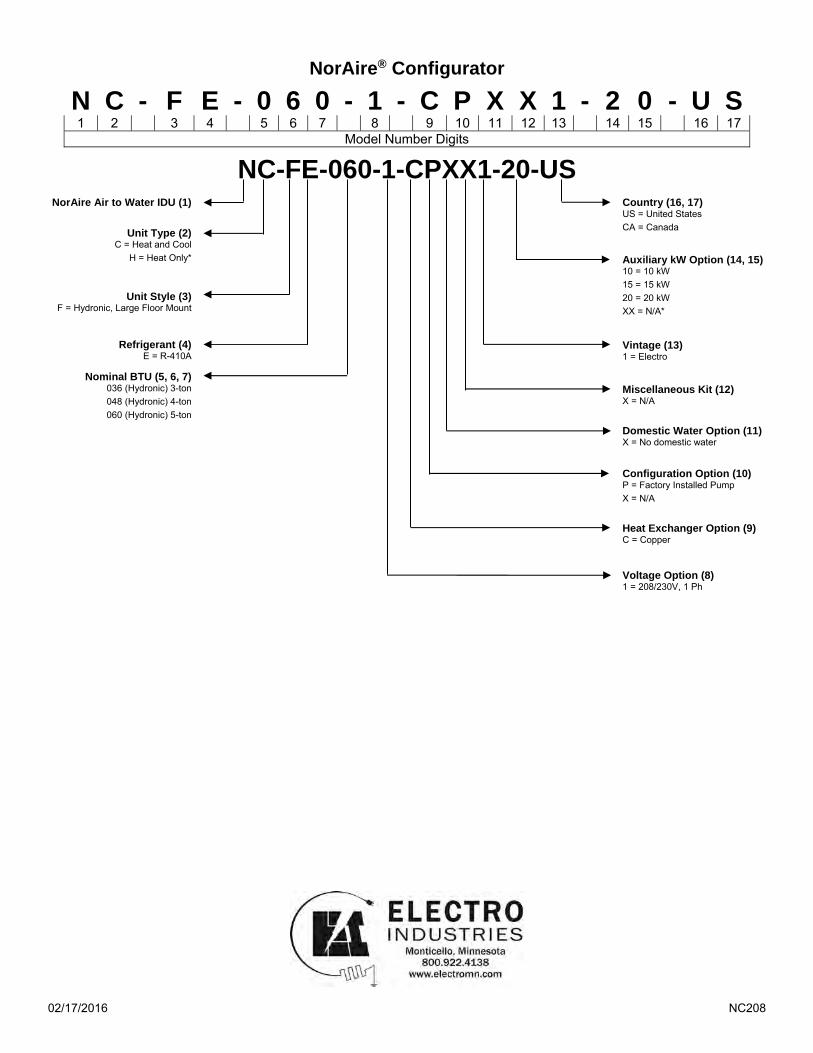
NorAire® Configurator
NC-FE-060-1-CPXX1-20-US
NorAire Air to Water IDU (1)
Unit Type (2) C = Heat and Cool
H = Heat Only*
Unit Style (3) F = Hydronic, Large Floor Mount
Refrigerant (4) E = R-410A
Nominal BTU (5, 6, 7)
036 (Hydronic) 3-ton 048 (Hydronic) 4-ton 060 (Hydronic) 5-ton
Country (16, 17) US = United States CA = Canada
Auxiliary kW Option (14, 15) 10 = 10 kW 15 = 15 kW 20 = 20 kW XX = N/A*
Vintage (13) 1 = Electro Miscellaneous Kit (12) X = N/A
Domestic Water Option (11) X = No domestic water
Configuration Option (10) P = Factory Installed Pump X = N/A Heat Exchanger Option (9) C = Copper Voltage Option (8) 1 = 208/230V, 1 Ph
N C - F E - 0 6 0 - 1 - C P X X 1 - 2 0 - U S 1 2 3 4 5 6 7 8 9 10 11 12 13 14 15 16 17
Model Number Digits
05/15/2020 4 NI216
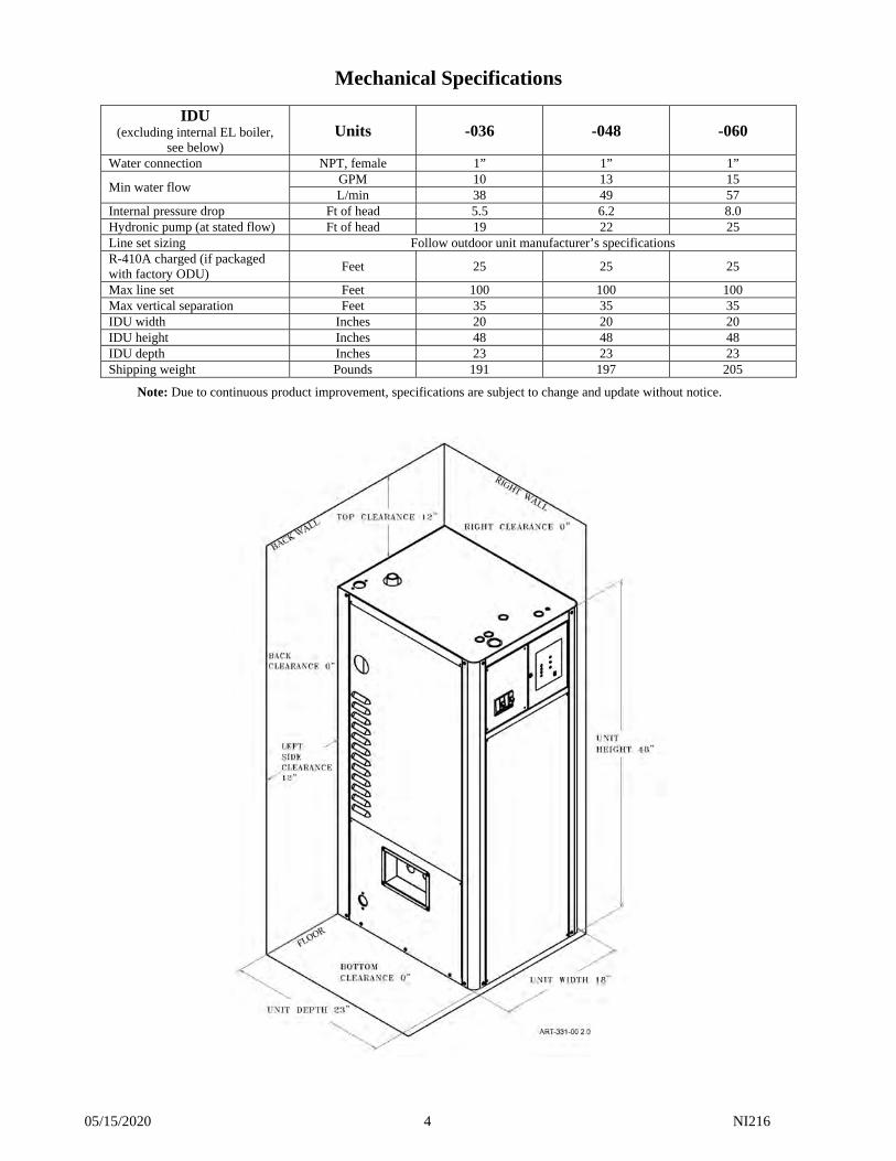
Mechanical Specifications
IDU (excluding internal EL boiler,
see below) Units -036 -048 -060
Water connection NPT, female 1” 1” 1”
Min water flow GPM 10 13 15 L/min 38 49 57
Internal pressure drop Ft of head 5.5 6.2 8.0 Hydronic pump (at stated flow) Ft of head 19 22 25 Line set sizing Follow outdoor unit manufacturer’s specifications R-410A charged (if packaged with factory ODU)
Feet 25 25 25
Max line set Feet 100 100 100 Max vertical separation Feet 35 35 35 IDU width Inches 20 20 20 IDU height Inches 48 48 48 IDU depth Inches 23 23 23 Shipping weight Pounds 191 197 205
Note: Due to continuous product improvement, specifications are subject to change and update without notice.
05/15/2020 5 NI216
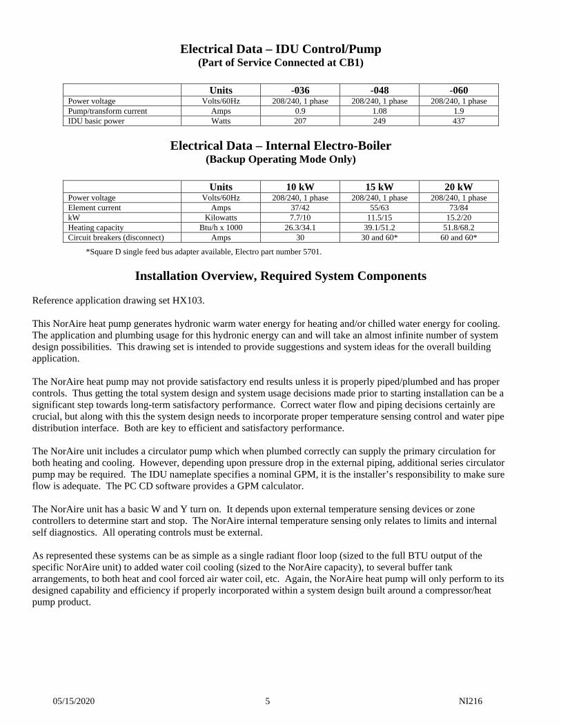
Electrical Data – IDU Control/Pump (Part of Service Connected at CB1)
Units -036 -048 -060
Power voltage Volts/60Hz 208/240, 1 phase 208/240, 1 phase 208/240, 1 phase Pump/transform current Amps 0.9 1.08 1.9 IDU basic power Watts 207 249 437
Electrical Data – Internal Electro-Boiler (Backup Operating Mode Only)
Units 10 kW 15 kW 20 kW
Power voltage Volts/60Hz 208/240, 1 phase 208/240, 1 phase 208/240, 1 phase Element current Amps 37/42 55/63 73/84 kW Kilowatts 7.7/10 11.5/15 15.2/20 Heating capacity Btu/h x 1000 26.3/34.1 39.1/51.2 51.8/68.2 Circuit breakers (disconnect) Amps 30 30 and 60* 60 and 60*
*Square D single feed bus adapter available, Electro part number 5701.
Installation Overview, Required System Components Reference application drawing set HX103. This NorAire heat pump generates hydronic warm water energy for heating and/or chilled water energy for cooling. The application and plumbing usage for this hydronic energy can and will take an almost infinite number of system design possibilities. This drawing set is intended to provide suggestions and system ideas for the overall building application. The NorAire heat pump may not provide satisfactory end results unless it is properly piped/plumbed and has proper controls. Thus getting the total system design and system usage decisions made prior to starting installation can be a significant step towards long-term satisfactory performance. Correct water flow and piping decisions certainly are crucial, but along with this the system design needs to incorporate proper temperature sensing control and water pipe distribution interface. Both are key to efficient and satisfactory performance. The NorAire unit includes a circulator pump which when plumbed correctly can supply the primary circulation for both heating and cooling. However, depending upon pressure drop in the external piping, additional series circulator pump may be required. The IDU nameplate specifies a nominal GPM, it is the installer’s responsibility to make sure flow is adequate. The PC CD software provides a GPM calculator. The NorAire unit has a basic W and Y turn on. It depends upon external temperature sensing devices or zone controllers to determine start and stop. The NorAire internal temperature sensing only relates to limits and internal self diagnostics. All operating controls must be external. As represented these systems can be as simple as a single radiant floor loop (sized to the full BTU output of the specific NorAire unit) to added water coil cooling (sized to the NorAire capacity), to several buffer tank arrangements, to both heat and cool forced air water coil, etc. Again, the NorAire heat pump will only perform to its designed capability and efficiency if properly incorporated within a system design built around a compressor/heat pump product.
05/15/2020 6 NI216
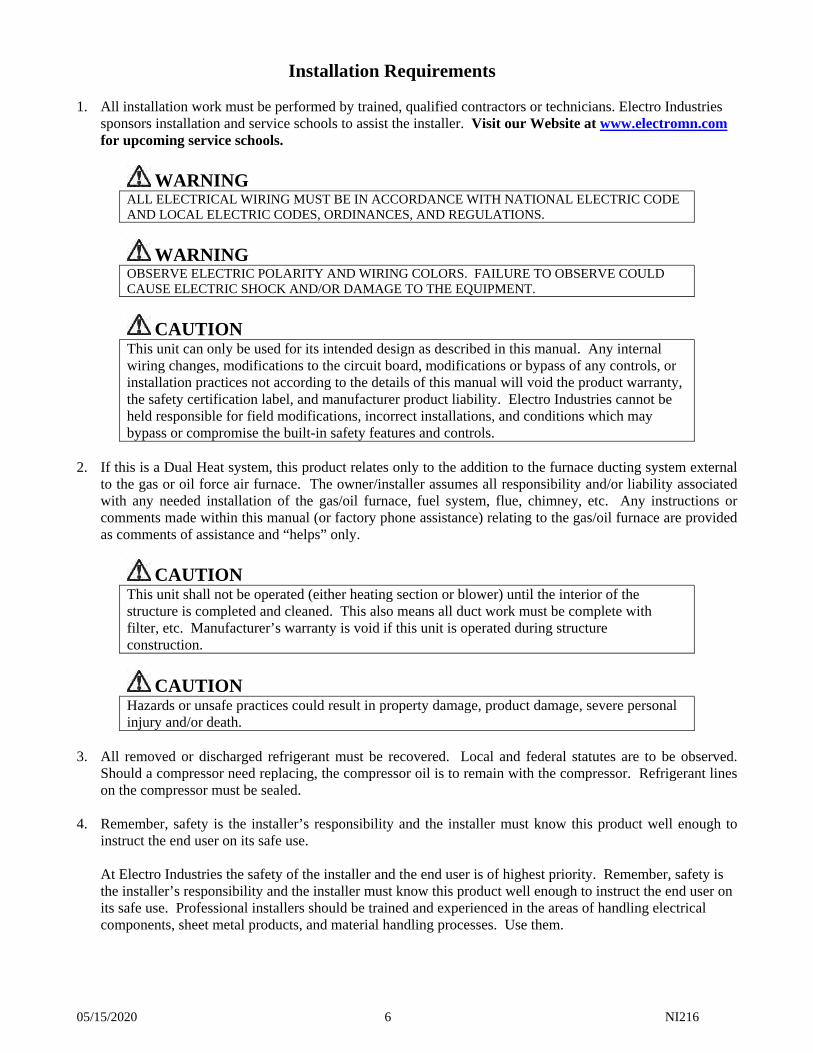
Installation Requirements 1. All installation work must be performed by trained, qualified contractors or technicians. Electro Industries
sponsors installation and service schools to assist the installer. Visit our Website at www.electromn.com for upcoming service schools.
WARNING ALL ELECTRICAL WIRING MUST BE IN ACCORDANCE WITH NATIONAL ELECTRIC CODE AND LOCAL ELECTRIC CODES, ORDINANCES, AND REGULATIONS.
WARNING OBSERVE ELECTRIC POLARITY AND WIRING COLORS. FAILURE TO OBSERVE COULD CAUSE ELECTRIC SHOCK AND/OR DAMAGE TO THE EQUIPMENT.
CAUTION This unit can only be used for its intended design as described in this manual. Any internal wiring changes, modifications to the circuit board, modifications or bypass of any controls, or installation practices not according to the details of this manual will void the product warranty, the safety certification label, and manufacturer product liability. Electro Industries cannot be held responsible for field modifications, incorrect installations, and conditions which may bypass or compromise the built-in safety features and controls.
2. If this is a Dual Heat system, this product relates only to the addition to the furnace ducting system external
to the gas or oil force air furnace. The owner/installer assumes all responsibility and/or liability associated with any needed installation of the gas/oil furnace, fuel system, flue, chimney, etc. Any instructions or comments made within this manual (or factory phone assistance) relating to the gas/oil furnace are provided as comments of assistance and “helps” only.
CAUTION This unit shall not be operated (either heating section or blower) until the interior of the structure is completed and cleaned. This also means all duct work must be complete with filter, etc. Manufacturer’s warranty is void if this unit is operated during structure construction.
CAUTION Hazards or unsafe practices could result in property damage, product damage, severe personal injury and/or death.
3. All removed or discharged refrigerant must be recovered. Local and federal statutes are to be observed.
Should a compressor need replacing, the compressor oil is to remain with the compressor. Refrigerant lines on the compressor must be sealed.
4. Remember, safety is the installer’s responsibility and the installer must know this product well enough to
instruct the end user on its safe use.
At Electro Industries the safety of the installer and the end user is of highest priority. Remember, safety is the installer’s responsibility and the installer must know this product well enough to instruct the end user on its safe use. Professional installers should be trained and experienced in the areas of handling electrical components, sheet metal products, and material handling processes. Use them.
05/15/2020 7 NI216
Mechanical Installation – Hydronic/Warm Water Output
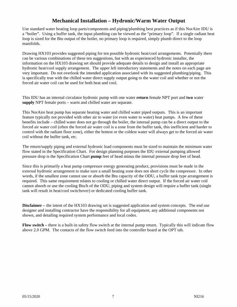
Use standard water heating loop parts/components and piping/plumbing best practices as if this NorAire IDU is a “boiler”. Using a buffer tank, the input plumbing can be viewed as the “primary loop”. If a single radiant heat loop is sized for the Btu output of the boiler, no primary loop is required, simply plumb direct to the loop manifolds. Drawing HX103 provides suggested piping for ten possible hydronic heat/cool arrangements. Potentially there can be various combinations of these ten suggestions, but with an experienced hydronic installer, the information on the HX103 drawing set should provide adequate details to design and install an appropriate hydronic heat/cool supply arrangement. The upper left introductory statements and the notes on each page are very important. Do not overlook the intended application associated with its suggested plumbing/piping. This is specifically true with the chilled water direct supply output going to the water coil and whether or not the forced air water coil can be used for both heat and cool. This IDU has an internal circulator hydronic pump with one water return female NPT port and two water supply NPT female ports – warm and chilled water are separate. This NorAire heat pump has separate heating water and chilled water piped outputs. This is an important feature typically not provided with other air to water (or even water to water) heat pumps. A few of these benefits include – chilled water does not go through the boiler, the internal pump can be a direct output to the forced air water coil (often the forced air water coil is a zone from the buffer tank, this inefficient and harder to control with the radiant floor zone), either the hottest or the coldest water will always get to the forced air water coil without the buffer tank, etc. The return/supply piping and external hydronic load components must be sized to maintain the minimum water flow stated in the Specification Chart. For design planning purposes the IDU external pumping allowed pressure drop is the Specification Chart pump feet of head minus the internal pressure drop feet of head. Since this is primarily a heat pump compressor energy generating product, provisions must be made in the external hydronic arrangement to make sure a small heating zone does not short cycle the compressor. In other words, if the smallest zone cannot use or absorb the Btu capacity of the ODU, a buffer tank type arrangement is required. This same requirement relates to cooling or chilled water direct output. If the forced air water coil cannot absorb or use the cooling Btu/h of the ODU, piping and system design will require a buffer tank (single tank will result in heat/cool switchover) or dedicated cooling buffer tank. Disclaimer – the intent of the HX103 drawing set is suggested application and system concepts. The end use designer and installing contractor have the responsibility for all equipment, any additional components not shown, and detailing required system performance and local codes. Flow switch – there is a built-in safety flow switch at the internal pump return. Typically this will indicate flow above 2.0 GPM. The contacts of the flow switch feed into the controller board at the OPT tab.
05/15/2020 8 NI216
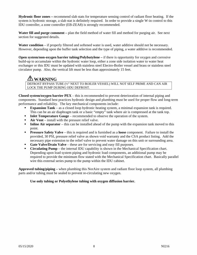
Hydronic floor zones – recommend slab stats for temperature sensing control of radiant floor heating. If the system is hydronic storage, a slab stat is definitely required. In order to provide a single W-in control to this IDU controller, a zone controller (EB-ZEA8) is strongly recommended. Water fill and purge comment – plan the field method of water fill and method for purging air. See next section for suggested details. Water condition – if properly filtered and softened water is used, water additive should not be necessary. However, depending upon the buffer tank selection and the type of piping, a water additive is recommended. Open system/non-oxygen barrier tubing/Polybutylene – if there is opportunity for oxygen and corrosive build-up to accumulate within the hydronic water loop, either a zone side isolation water to water heat exchanger or this IDU must be updated with stainless steel Electro-Boiler vessel and brass or stainless steel circulator pump. Also, the vertical lift must be less than approximately 15 feet.
WARNING DEFROST BYPASS TUBE (½” NEXT TO BOILER VESSEL) WILL NOT SELF PRIME AND CAN AIR LOCK THE PUMP DURING ODU DEFROST.
Closed system/oxygen barrier PEX – this is recommended to prevent deterioration of internal piping and components. Standard best practices hydronic design and plumbing must be used for proper flow and long-term performance and reliability. The key mechanical components include: Expansion Tank – as a closed loop hydronic heating system, a minimal expansion tank is required.
This can be an air diaphragm tank or a basic “empty” tank where air is compressed at the tank top. Inlet Temperature Gauge – recommended to observe the operation of the system. Air Vent – install with the pressure relief valve. Inline Air separator – this can be installed ahead of the pump with the expansion tank moved to this
point. Pressure Safety Valve – this is required and is furnished as a loose component. Failure to install the
provided, 30 PSI, pressure relief valve as shown void warranty and the CSA product listing. Add the necessary pipe extension to the relief valve to prevent water damage on this unit or surrounding area.
Gate Valve/Drain Valve – these are for servicing and easy fill purposes. Circulating Pump – the internal IDU capability is shown in the Mechanical Specification chart.
Depending upon load system piping and hydronic load components, an additional pump may be required to provide the minimum flow stated with the Mechanical Specification chart. Basically parallel wire this external series pump to the pump within the IDU cabinet.
Approved tubing/piping – when plumbing this NorAire system and radiant floor loop system, all plumbing parts and/or tubing must be sealed to prevent re-circulating new oxygen.
Use only tubing or Polyethylene tubing with oxygen diffusion barrier.
05/15/2020 9 NI216
Water Fill/Purge Procedure
Piping design and installation must include adequate shutoff valving and external connection valve/ports to force pressure water around the system without any pockets or air voids within all plumbing loops. Careful placement of these source and dump ports is very important with an in-between shutoff valve to make sure exiting air does not get back into the system or remain trapped.
IDU heating and chilled supply out – both need to be purged independent and care must be taken so when purging air does not re-enter the previous. Also, there is potential for trapped air within the internal defrost bypass loop which can cavitate the internal pump.
Suggested purge and fill – to properly work through heating and chilled water supply outputs, with the defrost bypass concern; it is mandatory that the installer perform proper purge and fill process. These next pages provide a step by step procedure, following this is not necessary but it is provided as a guide. However, the “purge or recheck defrost boiler bypass” section within this procedure is extremely important. This is over and above what is normally required for a typical boiler/hydronic system. IDU power-on and the aquastat type device (R to W or R to Y) should be active (installing technician could use an R to W or R to Y jumper). Note: After IDU power-on, must allow ACD timeout (power on LED is solid).
Basics
1. The pressure relief valve (R) is set at 30 psi. Verify there is an extension pipe bringing the output to a bucket or floor drain. Typically city water and well water is higher than 30 psi. Thus you will either need a regulator or a hand valve to manually make sure the hydronic circulating pressure is less than 30 psi so you do not “blow” the pressure relief. By throttling the introduced city water with a hand valve you can control the pressure within the hydronics loop down.
2. Do not run a hydronic circulator dry or without water flowing. The motor can overheat in a very short time and result in undesired troubleshooting conditions. A basic small hydronic circulator will not self prime or pull water. There must either be a column of water (3 to 4 feet high) above the inlet of the pump or a source pressure system which is initially forcing water through the pump. As little as a 1” to 3” air bubble within the inlet pipe can cavitate the pump and can stop circulation.
3. If there is a buffer tank, this should be totally filled before starting at the zone/loops. Remove the top plug or cap and fill completely.
4. Typically there will be more than one radiant loop and probably more than one zone (zone typically means several loops with a manifold collection). You must always start with one zone, then one loop, and when all loops are individually purged, you move on to the next zone and repeat. When you feel the previous zone is air purged, hand valve it closed, preferably on both sides of the manifold (A and B).
5. Determining when all the air is removed takes experience. Do not quit after it appears a set of bubbles are gone and there is now a clear stream of water. Typically you need to drain long enough to where there is a new circulation of water through the loop and system after seeing the last bubble. If a typical header piping and one 250-foot ½” loop holds 3.5 gallons and the city water is flowing at 2 GPM, you should continue to see a steady stream of water for 3 minutes.
6. For purge and fill purposes, a forced air water coil circuit is treated basically the same as a zone, the circuit must have its own input connection and drain connection with a valving method to force the city water all the way around the circuit.
7. Almost any pressure water source could be used for purging, but at the end you should consider refilling with a softened or mineral free water or rust inhibitor additives.
8. If your system needs antifreeze, first purge with a continuous water source and this procedure. If there is a buffer tank, drain out (all valves around the tank closed) the water equal to the antifreeze you need to add. Make sure the tank is totally filled (no air) before re-circulating system test and pressure verification, reference the following steps 10 through 17.
05/15/2020 10 NI216
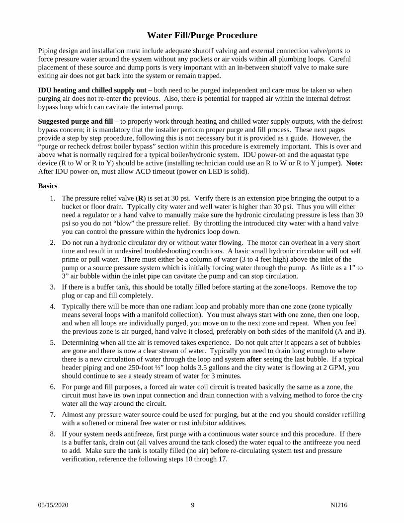
Radiant (Only) Heat Circuit Procedure
1. Condition the heat aquastat to on for 5 to 10 seconds (jumper R to W). The front panel STATUS light should be full on indicating the control board is set up for heating mode.
2. Connect a city water or well water source as shown.
3. If your system does not have a loop manifold with easily connected hose ports on each end (as shown), you will need to make a valving arrangement with two ports (hose bib) as shown on the next Cooling/Chilled Water Direct drawing.
4. Notice the two valves marked A and B. Again if your loop manifold does not have shutoff valves going to the leader pipe you should be installing these on your system.
5. Only open one loop (small valve above each tube), the others should be closed.
6. Begin with both A and B valves open. Begin introducing city water with hand valve S, being aware of Basics paragraph 1 above.
a. Flow is through the return manifold/NorAire IN/through boiler vessel/heating water OUT/through air separator/supply manifold top/drain.
b. This first pass will involve all of the above piping, thus the times mentioned in paragraph 5 above will not apply.
7. You should begin seeing air bubbles coming out of the drain hose. Reference paragraph 5 above, run the refill city water until you are absolutely sure all air is purged.
8. Move to the next floor loop by simultaneously opening the next and closing off the previous. Continue steps 5-7. Repeat until all radiant loops are air purge and water filled.
9. Simultaneously close valves A and B. Keep this zone circuit in this condition until all others are air purged and filled.
10. At the end keep city water and drain connected. At the IDU cabinet, left side, remove the side panel. This will allow easier viewing of the pressure/temperature gauge (also will need to be inside later for defrost bypass purging). Observe gauge, set at 15 psig. Turn off the city water source and close drain. But continue to keep the hoses connected.
WARNING – AVERTISSEMENT
RISK OF ELECTRIC SHOCK – CAN CAUSE INJURY OR DEATH RISQUE DE CHOCS ÉLECTRIQUES – PEUT CAUSER DES BLESSURES ET MÊME ENTRAÎNER LA MORT
05/15/2020 11 NI216
11. Control board, left center, locate a tab marked “pump”. Clip jumper R voltage to the “pump” tab. This will force the internal circulator pump on and you should be experiencing flow throughout the system.
12. Depending upon the air separator and air relief system, loosen the top air cap.
13. Open all manifold valves – A and B.
14. Depending upon the number of zones and the zone control system, the zone controller may need to be bypassed to activate zone valves or to turn on zone pumps to adequately verify flow within the total system.
15. If the pressure gauge goes down or fluctuates there is probably still air in the system. Again, depending upon the quality of the air separator it may purge out itself or you may need to start over.
16. Open all radiant zones and the manifold individual loop valves. Depending upon the manifold features, you may have small flow indicators which can verify equal or adequate flow in each loop.
17. After you feel comfortable there is good circulation and all the air has been purged, recheck pressure gauge. A one or two story building/house system with cold water should be set at about 10 to 12 psig. Using the still connected city water set correct pressure.
18. Disconnect city water hose and drain hose and remove the “pump” jumper.
Purge or Recheck Defrost Boiler Bypass
1. Setup or source/drain should be the same as above and in heating mode.
2. This should actually be run before step 15 above.
3. On the back of the NorAire control board, upper right, at the heat pump connection remove the “D” wire. Be prepared to clip jumper R to D.
4. This test needs to verify that the water going through the pump begins to heat up from the boiler during a simulated defrost. If it does not heat up at the pump (but the top of the boiler vessel gets hot), you must assume the ½” pipe between the vessel top and the tee at the pump input is air logged and has caused the pump to stop circulating.
5. Jumper heat pump R to D terminal block point, wait approximately 2 minutes and you should begin feeling warm water entering the pump. As time goes on the ½” pipe should be getting hotter and hotter because water is simply circulating through the boiler/pump/heat exchanger/ back through the boiler.
WARNING
DO NOT LEAVE THIS TEST UNATTENDED.
6. With confidence that the warm water is indeed circulating through the heat exchanger, remove the R to D jumper and replace the wire from the ODU into the D screw terminal block point (reference step 3 above).
7. Continue step 15 above.
05/15/2020 12 NI216
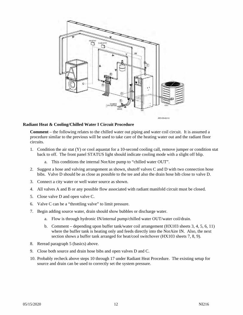
Radiant Heat & Cooling/Chilled Water I Circuit Procedure
Comment – the following relates to the chilled water out piping and water coil circuit. It is assumed a procedure similar to the previous will be used to take care of the heating water out and the radiant floor circuits.
1. Condition the air stat (Y) or cool aquastat for a 10-second cooling call, remove jumper or condition stat back to off. The front panel STATUS light should indicate cooling mode with a slight off blip.
a. This conditions the internal NorAire pump to “chilled water OUT”.
2. Suggest a hose and valving arrangement as shown, shutoff valves C and D with two connection hose bibs. Valve D should be as close as possible to the tee and also the drain hose bib close to valve D.
3. Connect a city water or well water source as shown.
4. All valves A and B or any possible flow associated with radiant manifold circuit must be closed.
5. Close valve D and open valve C.
6. Valve C can be a “throttling valve” to limit pressure.
7. Begin adding source water, drain should show bubbles or discharge water.
a. Flow is through hydronic IN/internal pump/chilled water OUT/water coil/drain.
b. Comment – depending upon buffer tank/water coil arrangement (HX103 sheets 3, 4, 5, 6, 11) where the buffer tank is heating only and feeds directly into the NorAire IN. Also, the next section shows a buffer tank arranged for heat/cool switchover (HX103 sheets 7, 8, 9).
8. Reread paragraph 5 (basics) above.
9. Close both source and drain hose bibs and open valves D and C.
10. Probably recheck above steps 10 through 17 under Radiant Heat Procedure. The existing setup for source and drain can be used to correctly set the system pressure.
05/15/2020 13 NI216
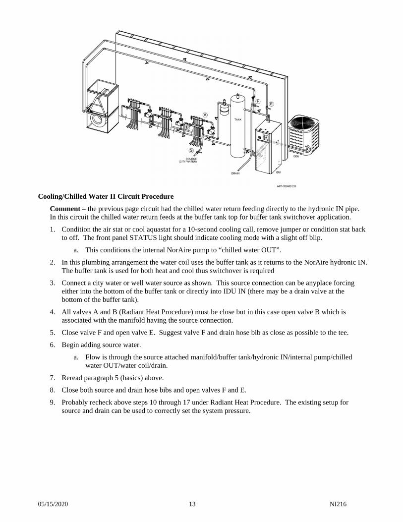
Cooling/Chilled Water II Circuit Procedure
Comment – the previous page circuit had the chilled water return feeding directly to the hydronic IN pipe. In this circuit the chilled water return feeds at the buffer tank top for buffer tank switchover application.
1. Condition the air stat or cool aquastat for a 10-second cooling call, remove jumper or condition stat back to off. The front panel STATUS light should indicate cooling mode with a slight off blip.
a. This conditions the internal NorAire pump to “chilled water OUT”.
2. In this plumbing arrangement the water coil uses the buffer tank as it returns to the NorAire hydronic IN. The buffer tank is used for both heat and cool thus switchover is required
3. Connect a city water or well water source as shown. This source connection can be anyplace forcing either into the bottom of the buffer tank or directly into IDU IN (there may be a drain valve at the bottom of the buffer tank).
4. All valves A and B (Radiant Heat Procedure) must be close but in this case open valve B which is associated with the manifold having the source connection.
5. Close valve F and open valve E. Suggest valve F and drain hose bib as close as possible to the tee.
6. Begin adding source water.
a. Flow is through the source attached manifold/buffer tank/hydronic IN/internal pump/chilled water OUT/water coil/drain.
7. Reread paragraph 5 (basics) above.
8. Close both source and drain hose bibs and open valves F and E.
9. Probably recheck above steps 10 through 17 under Radiant Heat Procedure. The existing setup for source and drain can be used to correctly set the system pressure.
05/15/2020 14 NI216
Mechanical Installation – Outdoor Unit (ODU) Consult and use details within the ODU manufacturer’s supplied installation manual. The refrigerant to water heat exchanger within this IDU is essentially the same as the refrigerant to air coil within the ODU manufacturer’s specified A-coil (dual fuel) or matched air handler. Since this is a heat pump (winter use) it needs to be installed off the ground, on a stand or blocks with at least 8” to 12” ice build-up space under the unit. This IDU includes an adjustable TXV expansion, common with air coils. This IDU only has a nitrogen charge. The ODU has extra charge volume for line set and this IDU internal heat exchanger (coax). See ODU installation manual for special line set slope conditions or oil trap if the elevation between the ODU and the IDU at a certain height. This ODU requires a field added filter/dryer; however, there are some ODU’s which have the filter/dryer internally installed, in this case do not use a loose filter/dryer. Add in the liquid line preferably at this IDU. Line set – use ODU manufacturer’s requirements for line set. However, since the IDU coax heat exchanger has a smaller charge volume than the typical forced air A-coil matched with this ODU, this IDU includes a refrigerant liquid receiver. There probably is no need to calculate extra charge for extra line set length because the IDU receiver will have as much as 16 oz. additional charge available.
Note: There is a concern for possible ODU overcharge, the IDU receiver may not take up the full ODU extra charger. Thus, it is very important during the power-up checks and adjustments to make sure the sub-cool/superheat is within tolerance shown within the ODU provided Operating Conditions chart or ODU nameplate chart.
Evacuate and leak check – as required with all air conditioning or heat pump line set installations, the prudent and proper vacuum pump down and leak check are required. The ODU manufacturer’s supplied installation manual details must be followed as well as refrigeration best practices.
05/15/2020 15 NI216
Electrical Hookup
IDU – Power Source – Reference NH220 From the internal circuit breakers, route and install the proper current carrying conductors to the building fuse or circuit breaker panel. See Electric Data specification chart or product nameplate for ratings. This IDU contains built-in circuit breakers and meets the requirement for local disconnect. CB1 is highest priority stage.
WARNING USE ONLY COPPER WIRE FOR CONNECTION TO THE CIRCUIT BREAKER TERMINALS AND INSIDE THIS PRODUCT’S CABINET.
If using single feed method, a single feed bus adapter is available, order part number 5701. Comment – the IDU internal circulator pump is pre-wired from CB1. Grounding – copper conductor is required, size per NEC/CSA code relating to the current of each feed.
WARNING TO AVOID THE RISK OF ELECTRIC SHOCK OR DEATH, WIRING TO THE UNIT MUST BE PROPERLY GROUNDED. FAILURE TO PROPERLY GROUND THE UNIT CAN RESULT IN A HAZARD LEADING TO PERSONAL INJURY OR DEATH.
Outdoor Unit (ODU) – Power Source See the appropriate nameplate and/or instruction manual supplied with the ODU. Control Hookup Reference drawing NH220 Aquastat (stat) – this heat pump system is basically turned on/off with a standard HVAC type R to W or R to Y. Piping suggestion drawing HX103 has various aquastat or thermostat suggestions. Sheet 2 could be a
single 4-wire air stat. Sheets 4 and 5 begin to become more complex. Outdoor Unit (ODU) – Control Five or six low voltage or thermostat type wires are required between this IDU and the ODU control wires. The IDU control board connection is the upper right 5-place terminal block (heat pump). Drawing NH220 page 1 provides general contact points and suggested wire colors.
Comment: In each particular shipment there may be a non-Electro ODU (see cover comment). In this case there will be a separate ODU hookup drawing associated with the specific ODU.
ODU with 2nd stage compressor – the HP-Y2 output is a K6 contact inside of the wiring compartment, behind the hinged controller door. Reference wiring schematic decal, UAW105, just above the color code chart is a K6 shown as an open contact. Typically this requires an R (or 24V) field connection on one tab and the 2nd tab is wired directly to the ODU HP-Y2.
05/15/2020 16 NI216
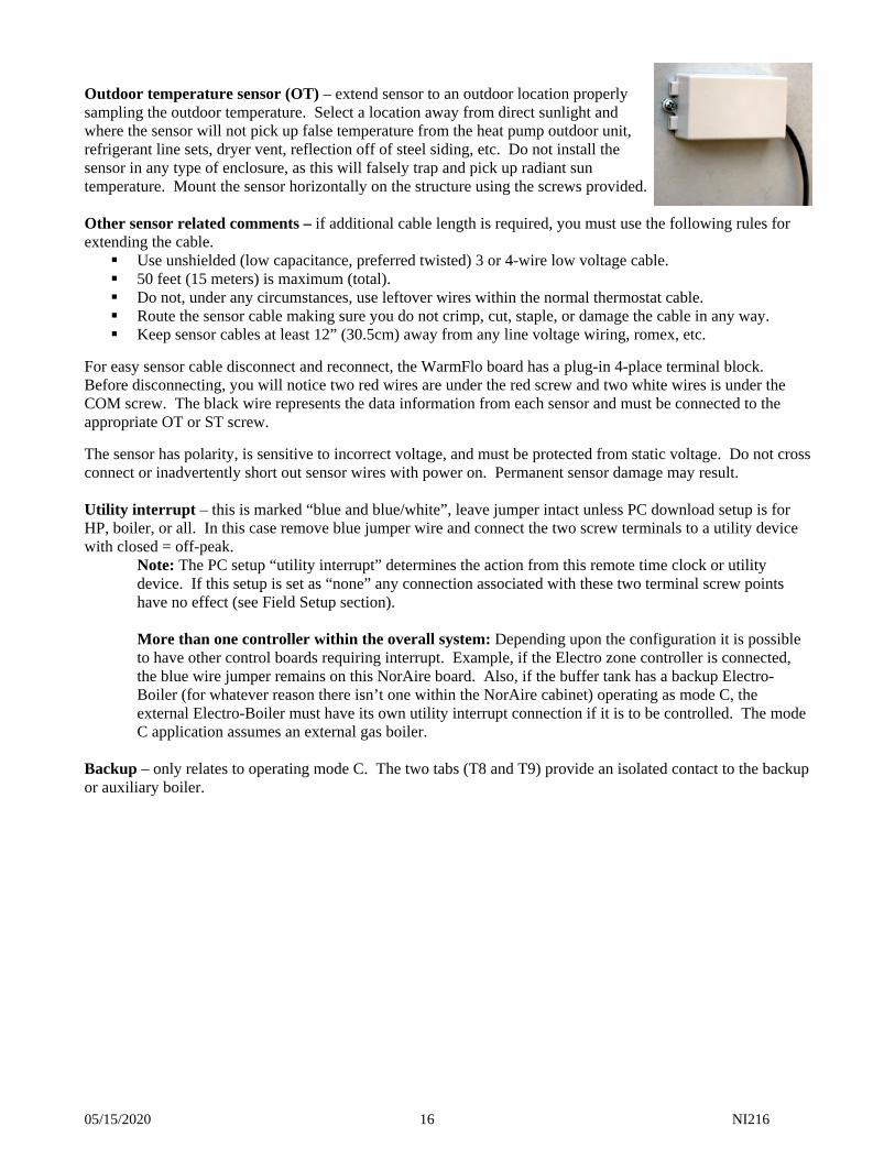
Outdoor temperature sensor (OT) – extend sensor to an outdoor location properly sampling the outdoor temperature. Select a location away from direct sunlight and where the sensor will not pick up false temperature from the heat pump outdoor unit, refrigerant line sets, dryer vent, reflection off of steel siding, etc. Do not install the sensor in any type of enclosure, as this will falsely trap and pick up radiant sun temperature. Mount the sensor horizontally on the structure using the screws provided. Other sensor related comments – if additional cable length is required, you must use the following rules for extending the cable. Use unshielded (low capacitance, preferred twisted) 3 or 4-wire low voltage cable. 50 feet (15 meters) is maximum (total). Do not, under any circumstances, use leftover wires within the normal thermostat cable. Route the sensor cable making sure you do not crimp, cut, staple, or damage the cable in any way. Keep sensor cables at least 12” (30.5cm) away from any line voltage wiring, romex, etc.
For easy sensor cable disconnect and reconnect, the WarmFlo board has a plug-in 4-place terminal block. Before disconnecting, you will notice two red wires are under the red screw and two white wires is under the COM screw. The black wire represents the data information from each sensor and must be connected to the appropriate OT or ST screw.
The sensor has polarity, is sensitive to incorrect voltage, and must be protected from static voltage. Do not cross connect or inadvertently short out sensor wires with power on. Permanent sensor damage may result. Utility interrupt – this is marked “blue and blue/white”, leave jumper intact unless PC download setup is for HP, boiler, or all. In this case remove blue jumper wire and connect the two screw terminals to a utility device with closed = off-peak.
Note: The PC setup “utility interrupt” determines the action from this remote time clock or utility device. If this setup is set as “none” any connection associated with these two terminal screw points have no effect (see Field Setup section).
More than one controller within the overall system: Depending upon the configuration it is possible to have other control boards requiring interrupt. Example, if the Electro zone controller is connected, the blue wire jumper remains on this NorAire board. Also, if the buffer tank has a backup Electro-Boiler (for whatever reason there isn’t one within the NorAire cabinet) operating as mode C, the external Electro-Boiler must have its own utility interrupt connection if it is to be controlled. The mode C application assumes an external gas boiler.
Backup – only relates to operating mode C. The two tabs (T8 and T9) provide an isolated contact to the backup or auxiliary boiler.
05/15/2020 17 NI216
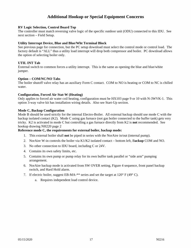
Additional Hookup or Special Equipment Concerns
RV Logic Selection, Control Board Top The controller must match reversing valve logic of the specific outdoor unit (ODU) connected to this IDU. See next section – Field Setup. Utility Interrupt Device, Blue and Blue/Wht Terminal Block See previous page for connection, but the PC setup download must select the control mode or control load. The factory default is “ALL” thus a utility load interrupt will drop both compressor and boiler. PC download allows the option of selecting boiler only. UTIL INT Tab External switch to common forces a utility interrupt. This is the same as opening the blue and blue/white jumper. Option – COM/NC/NO Tabs The boiler shutoff valve relay has an auxiliary Form C contact. COM to NO is heating or COM to NC is chilled water. Configuration, Forced Air Stat-W (Heating) Only applies to forced air water coil heating, configuration must be HX103 page 9 or 10 with N-3WVK-1. This option 3-way valve kit has installation wiring details. Also see Start-Up section. Mode C, Backup Configuration Mode B should be used strictly for the internal Electro-Boiler. All external backup should use mode C with the backup isolated contact (K2). Mode C using gas furnace (not gas boiler connected to the buffer tank) gets very tricky. K2 is activated in mode C but controlling a gas furnace directly from K2 is not recommended. See hookup drawing NH220 page 2 Reference mode C, the requirements for external boiler, backup mode:
1. This external boiler shall not be piped in series with the NorAire in/out (internal pump).
2. NorAire W-in controls the boiler via K1/K2 isolated contact – bottom left, Backup COM and NO.
3. No other connection to IDU board, including C or 24V.
4. Contains its own safety limits, etc.
5. Contains its own pump or pump relay for its own buffer tank parallel or “side arm” pumping arrangement.
6. NorAire backup mode is activated from SW OVER setting, Figure 4 sequence, front panel backup switch, and Hard Hold alarm.
7. If electric boiler, suggest EB-MA-** series and set the target at 120° F (49° C).
a. Requires independent load control device.
05/15/2020 18 NI216
Variable Speed Pump Variable pump can be used on the load side of the buffer tank, but not in the NorAire supply OUT circuits. Low Flow, Need Larger Pump If the IDU internal pump does not have adequate capacity or lift, add a series 2nd pump at the IDU “IN” pipe and wire in parallel to the internal pump (240VAC). However, one of the OUT’s may have higher flow resistance (head). In this case adding a small series pump in the OUT may be the best solution. E-Tab (Compressor No Response) If the connected ODU has an “L” or a fault wire available, extend this wire to the E tab. This must be a continuous 24V, not pulsing or “flashes”. When this is raised to 24VAC, this controller assumes the compressor is off and provides an alarm front panel LED plus initiates backup or emergency heat. The HP-Y will continue until either stat W or stat Y is satisfied. Cycling of either stat W or Y will reset and the IDU controller will go through a sequence of again evaluating the E tab input. Pump Tab An external contact from R to “pump” tab forces internal pump relay on. This will override any internal software sequence. PC Remote Default or Setup Downloads The controller left pin connector (J5) receives the Electro Industries’ special cable for PC communication to this controller (order ET-SOFT-NA-USB). See the instruction sheet or software CD Help file accompanying this cable. Comment – No Factory Installed Electric Boiler If the radiant system return (RT) is < 70° F (21° C) there may be an ODU defrost delay and problem. Adequate refrigerant energy may not be developed from cold return water to properly defrost and permanent freeze-up of the ODU may occur. ODU with 2nd Stage Compressor Where this applies, see page 15 bottom and the K6 wiring.
05/15/2020 19 NI216
Field Setup or Programming
RV Logic Pin Jumper This is located on the controller board top. It establishes the voltage at the heat pump (right top terminal block) RV screw terminal logic to the ODU. Various ODU manufacturers have either a high or low reversing logic concept. This is a 3-prong arrangement; the 2-position pin jumper will either have the center prong shorted to the left or to the right. H/B position – 24 volts for heating (factory default) C/O position – 24 volts for cooling
Operating Mode This rotary dial switch determines the various system configurations and must be set by the installer.
Note: A power-down and power-up reset is required each time the position of this mode switch is changed. A – heat pump only B – heat pump with internal boiler boost and backup (factory default) C – heat pump with external boiler backup D – not used
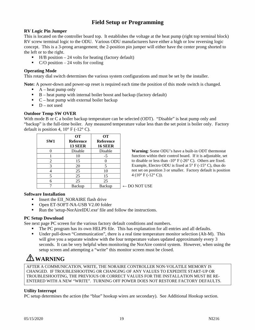
Outdoor Temp SW OVER With mode B or C a boiler backup temperature can be selected (ODT). “Disable” is heat pump only and “backup” is the full-time boiler. Any measured temperature value less than the set point is boiler only. Factory default is position 4, 10° F (-12° C).
SW1 OT
Reference 13 SEER
OT Reference 16 SEER
0 Disable Disable Warning: Some ODU’s have a built-in ODT thermostat function within their control board. If it is adjustable, set to disable or less than -10° F (-26° C). Others are fixed. Example, Electro ODU is fixed at 5° F (-15° C), thus do not set on position 3 or smaller. Factory default is position 4 (10° F (-12° C)).
1 10 -5 2 15 0 3 20 5 4 25 10 5 25 15 6 25 25 7 Backup Backup ← DO NOT USE
Software Installation Insert the EII_NORAIRE flash drive Open ET-SOFT-NA-USB V2.00 folder Run the 'setup-NorAireIDU.exe' file and follow the instructions.
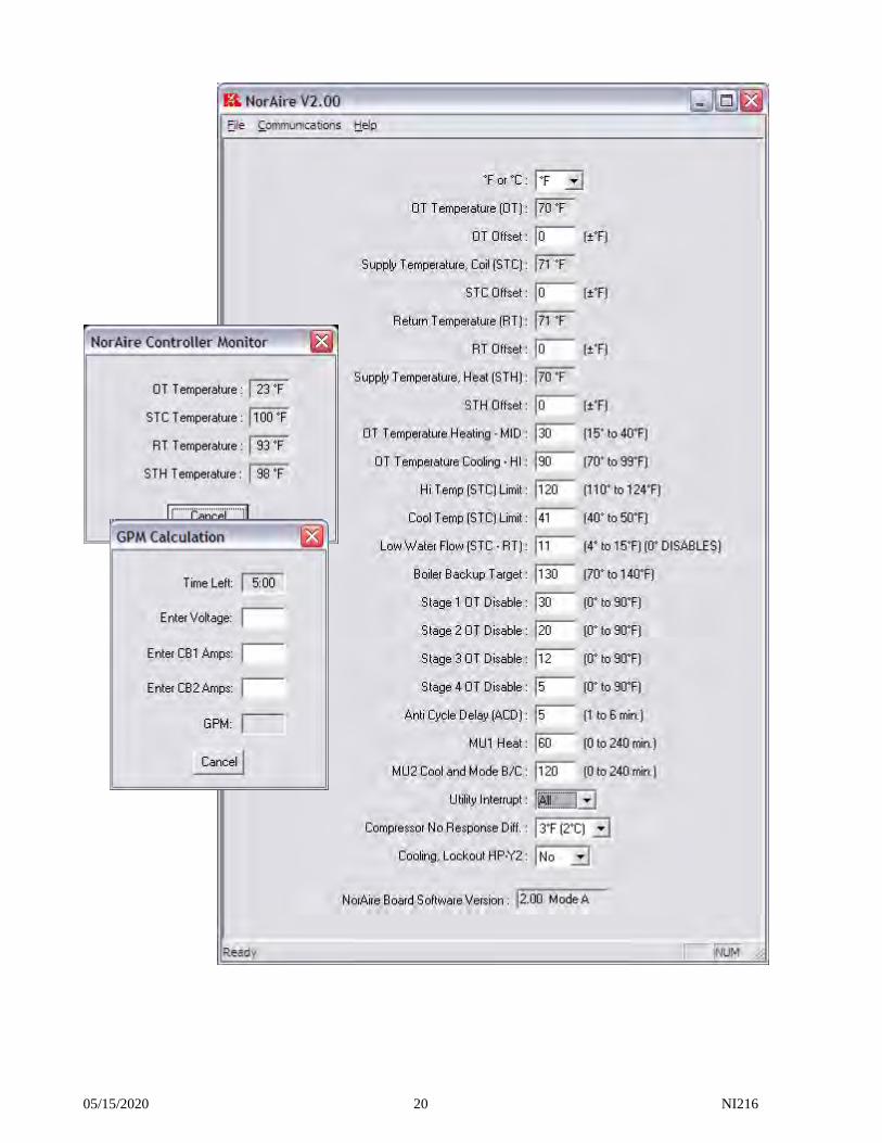
PC Setup Download See next page PC screen for the various factory default conditions and numbers. The PC program has its own HELPS file. This has explanation for all entries and all defaults. Under pull-down “Communication”, there is a real time temperature monitor selection (Alt-M). This
will give you a separate window with the four temperature values updated approximately every 3 seconds. It can be very helpful when monitoring the NorAire control system. However, when using the setup screen and attempting a “write” this monitor screen must be closed.
WARNING
AFTER A COMMUNICATION, WRITE, THE NORAIRE CONTROLLER NON-VOLATILE MEMORY IS CHANGED. IF TROUBLESHOOTING OR CHANGING OF ANY VALUES TO EXPEDITE START-UP OR TROUBLESHOOTING, THE PREVIOUS OR CORRECT VALUES FOR THE INSTALLATION MUST BE RE-ENTERED WITH A NEW “WRITE”. TURNING OFF POWER DOES NOT RESTORE FACTORY DEFAULTS.
Utility Interrupt PC setup determines the action (the “blue” hookup wires are secondary). See Additional Hookup section.
05/15/2020 20 NI216
05/15/2020 21 NI216
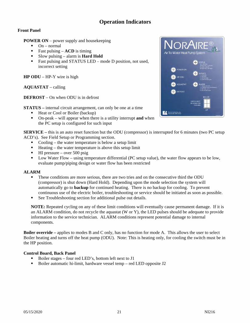
Operation Indicators
Front Panel POWER ON – power supply and housekeeping On – normal Fast pulsing – ACD is timing Slow pulsing – alarm is Hard Hold Fast pulsing and STATUS LED – mode D position, not used,
incorrect setting HP ODU – HP-Y wire is high AQUASTAT – calling DEFROST – On when ODU is in defrost STATUS – internal circuit arrangement, can only be one at a time Heat or Cool or Boiler (backup) On-peak – will appear when there is a utility interrupt and when
the PC setup is configured for such input
SERVICE – this is an auto reset function but the ODU (compressor) is interrupted for 6 minutes (two PC setup ACD’s). See Field Setup or Programming section. Cooling – the water temperature is below a setup limit Heating – the water temperature is above this setup limit HI pressure – over 500 psig Low Water Flow – using temperature differential (PC setup value), the water flow appears to be low,
evaluate pump/piping design or water flow has been restricted
ALARM These conditions are more serious, there are two tries and on the consecutive third the ODU
(compressor) is shut down (Hard Hold). Depending upon the mode selection the system will automatically go to backup for continued heating. There is no backup for cooling. To prevent continuous use of the electric boiler, troubleshooting or service should be initiated as soon as possible.
See Troubleshooting section for additional pulse out details.
NOTE: Repeated cycling on any of these limit conditions will eventually cause permanent damage. If it is an ALARM condition, do not recycle the aquastat (W or Y), the LED pulses should be adequate to provide information to the service technician. ALARM conditions represent potential damage to internal components.
Boiler override – applies to modes B and C only, has no function for mode A. This allows the user to select Boiler heating and turns off the heat pump (ODU). Note: This is heating only, for cooling the switch must be in the HP position. Control Board, Back Panel Boiler stages – four red LED’s, bottom left next to J1 Boiler automatic hi-limit, hardware vessel temp – red LED opposite J2
05/15/2020 22 NI216
User Instructions
External Aquastat or Controlling Thermostat All operate on or off functions are controlled by the external aquastat or thermostat device connected to the W (heating) or Y (cooling) terminal screw. Thus the user must become familiar with his/her hydronic system design and hydronic (heat or cool) temperature control. The heat or cool system can be monitored by the front panel seven LED lights, see previous page. If the SERVICE light repeatedly comes on after initial installation, the system design needs to be further evaluated and corrected. For corrective action, note the status indication and associate with the SERVICE light counts. This will assist in determining the problem.
Note: If there appears to be reduced capacity or inefficient performance, observe the SERVICE (and ALARM) light for a complete heat or cool thermostat cycle.
If the ALARM light is on (or repeats), one of the conditions shown has been sensed. This can initiate a Hard Hold which means in mode B or C the backup boiler will be controlled by stat W input. The boiler is on until the W input is satisfied. The next W input basically cancels the Hard Hold and the internal alarm sequence and sensor evaluation repeats. This should prevent winter freeze-up, but service and repair must be taken care of as soon as possible. The front panel switch could be moved to the boiler position thus preventing this continual cycling and “hunting” without any result. Setup & Options The Field Setup or Programming section in this manual may also have user information and attention requirements. The Additional Hookup or Special Equipment Concerns section may have optional or accessory installed items which will require user attention. Configuration Attached HX103 drawing set provides various plumbing/piping possibilities for typical hydronic system. If possible it will be beneficial for the user to relate an appropriate piping drawing to his/her installed system. The upper left descriptive statements and notes are very important. Btu/h sizing of the cooling forced air water coil and determining whether this forced air water coil is cooling only or needs to be heating and cooling will become significant for proper operating efficiency and long-term heat pump operating life. The heat pump system needs long run periods, short cycling is harmful and very inefficient, and the front panel SERVICE or ALARM light should never come on unless there is a flow or hydronic load deterioration or failure. This IDU has the output or load circulator pump installed. Typically in most plumbing arrangements for radiant floor heating or with cooling only forced air water coil, the internal pump is adequate. However, this internal pump only has a fixed circulation pressure or flow rate, if there is not adequate water flow to the field connected load devices, inefficiencies will develop. In some cases an additional series pump in either the heat output pipe or the chilled water direct output pipe may be required. See Preventative Maintenance section for proper component care.
05/15/2020 23 NI216
Control Sequence Information
Basic – first, there are six factors or “variable” which need to be reviewed before beginning your analysis of the control sequence. Field setup or programming – see previous section Outdoor temperature sensor (OT reported value) – defines which operating line within the next page
sequence charts Mode selection – determines backup or auxiliary relationship to the heat pump system Stat – the external W and Y inputs which begin the sequence process, set up internal safety monitors,
starts various built-in diagnostics, and the basic operation flow Front panel lights – see Operation Indicators section, it is important to observe and determine any
abnormal conditions
Turn-on or go – this controller is in wait or idle condition until there is either a W or Y input. This W or Y input can come from an external room thermostat, water temperature sensing aquastat, zone controller (W-OUT), another temperature sensing and process controller, etc. W call – configures the internal process for the heat pump and internal electric boiler to produce heating
water out. Y call – configures the internal process for the heat pump to product chilled water out.
From the above the controller follows the appropriate Figure 1, 2, 3, or 4 sequence chart.
Sequence chart definitions – these comments should assist in communicating the microprocessor operation. OT – the specific line selection is controlled by above or below the outdoor temperature value. For
illustration purposes, the OT value is the factory default from the PC setup. MU1 – a timer which begins with the W input. The setup default value is 60 minutes. MU2 – a timer which begins with Y or W input. The setup default value is 120 minutes. Heat pump – controller output action at the Heat Pump terminal block. INT – the result of utility interrupt remote device. However, depends upon setup utility interrupt
selection illustrated in Figure 5. SW OVER – the above or below OT temperature as selected by the SW OVER dial switch. Probably
do not use positions 7 or 0, the front panel switch is more convenient. If the OT temperature changes to affect a specific line item, the sequence finishes out the W call.
Boiler – internal electric boiler action. K2 close – isolated contact for starting and stopping external water heating boiler.
Note: All backup or boiler finish out stat W call before resetting back to heat pump. Chart modes B and C are very similar. Mode B activates the internal Electro-Boiler with stage 1 modulation (line 4) and lines 5 and 7 the boiler operates at the setup boiler target temperature. Mode C simply closes and opens the backup relay contact continuous until stat-W call is satisfied. The external boiler connected to the backup contact must have its own limits or temperature sensing.
Internal housekeeping or overrides – these can effect an expected observation and need to be considered. Anti-cycle delay (ACD) – at power-up, and each time there is a compressor interrupt or a change in
compressor mode, there is a 5-minute (setup) wait or delay. During ACD there is no stat input checking, no outputs, no 3-way valve motor, etc. At the end of ACD all appropriate monitors, logic sequence, and outputs take place. If the connected ODU has its own ACD timer, the PC setup time for this IDU function must be the same or slightly longer.
Internal pump – follows W or Y call, is active 30 seconds before compressor turn-on, and continues 60 seconds after the completion of W or Y call. There is also a jumper tab turn-on override provided and the pump is held on through any defrost cycle.
Backup – this mode is activated from the front panel switch, below SW OVER setting, or alarm Hard Hold. If mode B, the electric boiler will be controlled by its built-in temperature sensor and the stages are modulated at its target temperature (factory default is 130° F (54° C)). If mode C, the “backup” contact is closed and further controlled by W call. There is no controller temperature sensing relating to mode C backup contact.
05/15/2020 24 NI216
Electric boiler stage OT disable temperatures – there is a PC setup outdoor temperature assigned to each of the four boiler element stages. If the OT reported value is greater than this disable, the appropriate stage will not be active.
Low water flow – 6 minutes after W call and heat pump active, the return water (RT) temperature is subtracted from the heat exchanger supply water (STc) temperature. If this differential is greater than the PC setup value (factory default 11° F (6° C)), the service LED and sequence are activated.
Pressure/temperature limit – there are safety and diagnostic temperature and pressure sensors which can interrupt the “Y1” control wire to the ODU. These are observed by the SERVICE light, see Operational Indicators section. The heat and cool temperatures have factory default values (120° F (49° C) and 41° F (5° C)) but the pressure is fixed at 500 psig.
No water flow – internally at the “IN” water pipe is a flow switch. This is checked 20 seconds after a stat W or Y call (before compressor turns on). The controller bottom OPT tab must be switched to board common by the flow switch.
Return < 42° F – this test makes sure the hydronic water is not too cold for proper heat pump/refrigerant cycle operation. See Troubleshooting section.
ODU 2nd stage (HP-Y2) – this is an available output for ODU’s having PL and FL capability (see sequence chart, next page). Also, the connection or hookup (back panel relay) for this function is detailed relating to the specific ODU which has 2nd stage capability.
ALARM/Hard Hold – these limit conditions cycle off similar to the SERVICE limits with two retries separated by two ACD delay times. At the third retry the controller declares Hard Hold. If mode B or C, the W call will begin controlling the backup heat. When Hard Hold is declared HP-Y1 or ODU is off, pump is on, power-on LED is slow pulsing, and the W input now controls the internal electric boiler and “backup” K2 contact. The backup boiler will continue until the stat W call is completed. At this point the next stat W or Y call cancels the Hard Hold condition and the NorAire controller sequence again evaluates these inputs. If it processes through to the next Hard Hold, the stat W call will use the backup boiler to provide heating energy and prevent building freeze-up. Freeze protect, count 1 – with a Y input or during the full chilled water mode, the temperature at the
heat exchanger output is equal to or below 38° F (3° C), alarm is initiated. Compressor no response, count 2 – this is an important diagnostic and safety feature. It allows certain
indicators to the user but more importantly it automatically switches to backup to prevent building freeze-up or major discomfort. There are two internal sequence logic methods to detect “dead” ODU – ODU fault wire connected to E-tab OR an internal temperature comparison sequence. See Troubleshooting section. This Alarm indicator LED (or Service LED) provides no diagnostic information about the ODU. ODU diagnostic information must be determined from the control board within the ODU.
Return < 42° F, count 3 – 20 seconds after HP-Y1 or heat pump on, the return water sensor is checked. If at any time after the initial 20 seconds the return water is < 42° F, shut down and this alarm is declared.
No water flow, count 4 – 20 seconds after stat-W or Y, the flow switch input, OPT tab, is checked. If it indicates an open, no flow is declared.
Note: The Hard Hold visual status or internal logic condition actually is not reset until there is a new stat-W (or Y) call. This allows further opportunity to evaluate the alarm condition. Note: As soon as the user recognizes an ALARM condition, copy down the pulse count and the alarm cause. At this point the continual sequencing of alarm conditions can be terminated by the user setting the front panel switch to “boiler” for continuous heating with the internal Electro-Boiler or mode C backup relay contact.
05/15/2020 25 NI216
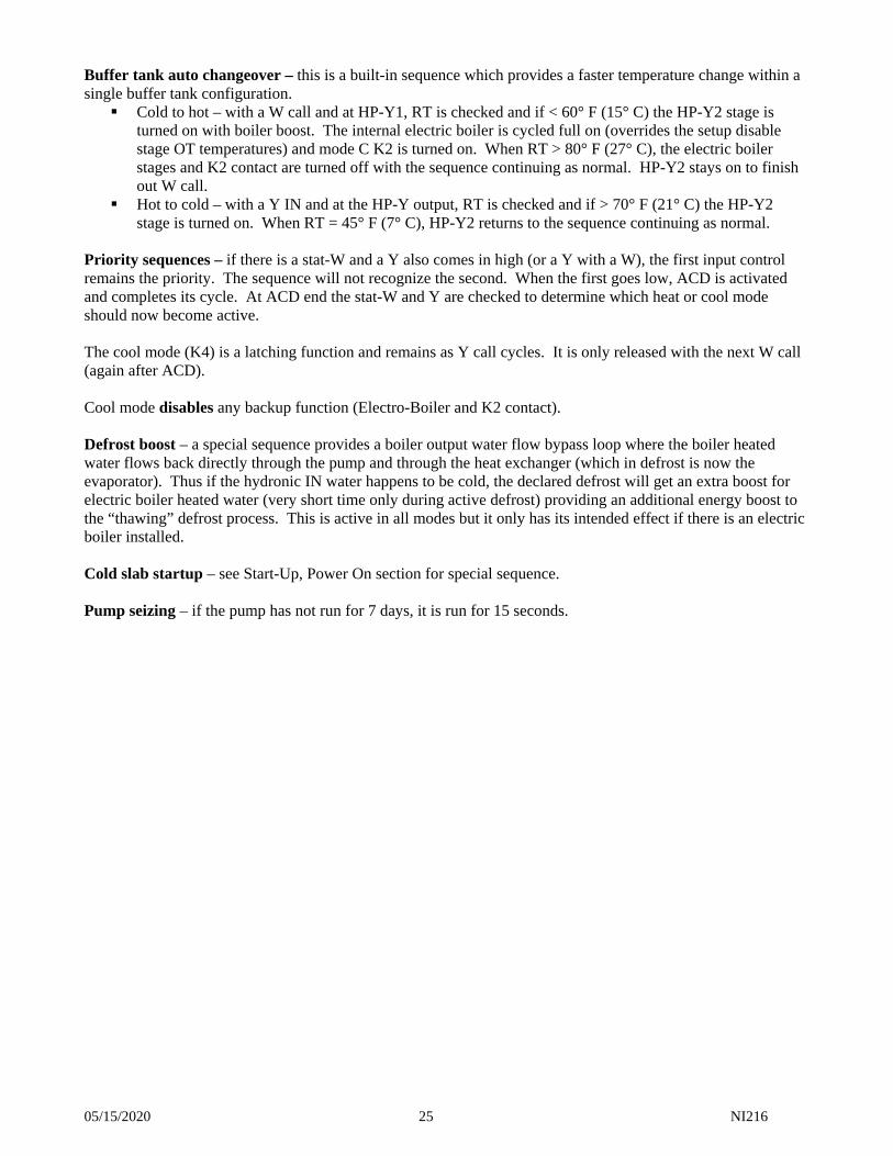
Buffer tank auto changeover – this is a built-in sequence which provides a faster temperature change within a single buffer tank configuration. Cold to hot – with a W call and at HP-Y1, RT is checked and if < 60° F (15° C) the HP-Y2 stage is
turned on with boiler boost. The internal electric boiler is cycled full on (overrides the setup disable stage OT temperatures) and mode C K2 is turned on. When RT > 80° F (27° C), the electric boiler stages and K2 contact are turned off with the sequence continuing as normal. HP-Y2 stays on to finish out W call.
Hot to cold – with a Y IN and at the HP-Y output, RT is checked and if > 70° F (21° C) the HP-Y2 stage is turned on. When RT = 45° F (7° C), HP-Y2 returns to the sequence continuing as normal.
Priority sequences – if there is a stat-W and a Y also comes in high (or a Y with a W), the first input control remains the priority. The sequence will not recognize the second. When the first goes low, ACD is activated and completes its cycle. At ACD end the stat-W and Y are checked to determine which heat or cool mode should now become active. The cool mode (K4) is a latching function and remains as Y call cycles. It is only released with the next W call (again after ACD). Cool mode disables any backup function (Electro-Boiler and K2 contact). Defrost boost – a special sequence provides a boiler output water flow bypass loop where the boiler heated water flows back directly through the pump and through the heat exchanger (which in defrost is now the evaporator). Thus if the hydronic IN water happens to be cold, the declared defrost will get an extra boost for electric boiler heated water (very short time only during active defrost) providing an additional energy boost to the “thawing” defrost process. This is active in all modes but it only has its intended effect if there is an electric boiler installed. Cold slab startup – see Start-Up, Power On section for special sequence. Pump seizing – if the pump has not run for 7 days, it is run for 15 seconds.
05/15/2020 26 NI216
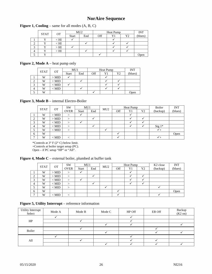
NorAire Sequence
Figure 1, Cooling – same for all modes (A, B, C)
STAT OT MU2 Heat Pump INT
(blues) Start End Off Y1 Y2 1 Y < HI 2 Y < HI 3 Y > HI 4 Y > HI 5 Y Open
Figure 2, Mode A – heat pump only
STAT OT MU1 Heat Pump INT
(blues) Start End Off Y1 Y2 1 W > MID 2 W > MID 3 W < MID 4 W < MID 5 W Open
Figure 3, Mode B – internal Electro-Boiler
STAT OT SW
OVER MU1
MU2 Heat Pump Boiler
(backup) INT
(blues) Start End Off Y1 Y2 1 W > MID > 2 W > MID > 3 W < MID > 4 W < MID > Stg 1* 5 W < MID > + 6 W Open 7 W < MID < +
*Controls at 3° F (2° C) below limit. +Controls at boiler target setup (PC). Open – if PC setup “HP” or “All”.
Figure 4, Mode C – external boiler, plumbed at buffer tank
STAT OT SW
OVER MU1
MU2 Heat Pump K2 close
(backup) INT
(blues) Start End Off Y1 Y2 1 W > MID > 2 W > MID > 3 W < MID > 4 W < MID > 5 W < MID > 6 W Open 7 W < MID <
Figure 5, Utility Interrupt – reference information
Utility Interrupt Select
Mode A Mode B Mode C HP Off EB Off Backup (K2 on)
HP
Boiler
All
05/15/2020 27 NI216
Start-Up, Power On
Installation check points: 1. Verify hydronic piping/chilled water system has been properly filled and purged – see Water Fill/Purge
Procedure section. 2. Recheck electrical sections within this installation manual – Electrical Data, Electrical Hookup, and
Additional Hookup or Special Equipment Concerns. 3. Verify all electric connections are proper per NEC or CSA code and tight or properly torqued. 4. Re-familiarize yourself with Operator Indicators and Control Sequence Information sections. 5. In order to complete all the service/alarm checks, more than 6 minutes continuous run time is required.
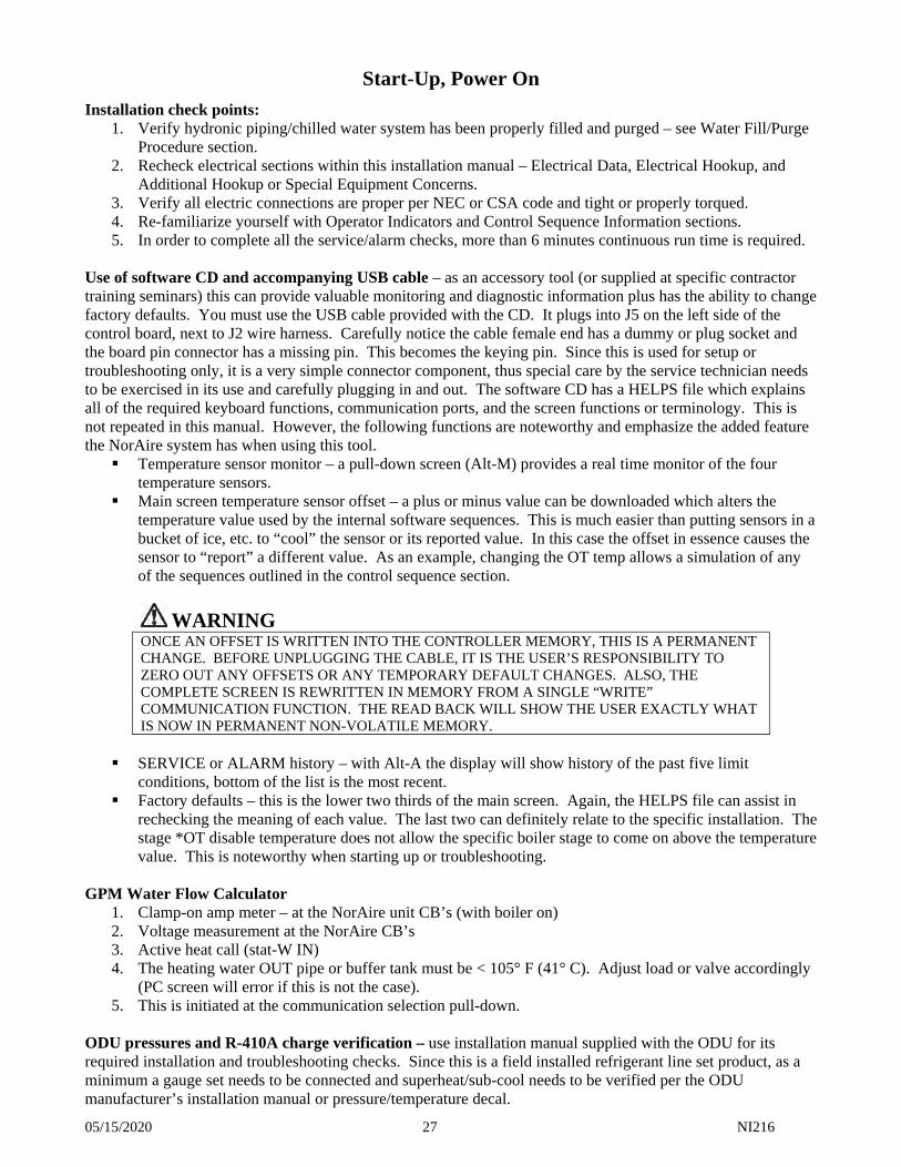
Use of software CD and accompanying USB cable – as an accessory tool (or supplied at specific contractor training seminars) this can provide valuable monitoring and diagnostic information plus has the ability to change factory defaults. You must use the USB cable provided with the CD. It plugs into J5 on the left side of the control board, next to J2 wire harness. Carefully notice the cable female end has a dummy or plug socket and the board pin connector has a missing pin. This becomes the keying pin. Since this is used for setup or troubleshooting only, it is a very simple connector component, thus special care by the service technician needs to be exercised in its use and carefully plugging in and out. The software CD has a HELPS file which explains all of the required keyboard functions, communication ports, and the screen functions or terminology. This is not repeated in this manual. However, the following functions are noteworthy and emphasize the added feature the NorAire system has when using this tool. Temperature sensor monitor – a pull-down screen (Alt-M) provides a real time monitor of the four
temperature sensors. Main screen temperature sensor offset – a plus or minus value can be downloaded which alters the
temperature value used by the internal software sequences. This is much easier than putting sensors in a bucket of ice, etc. to “cool” the sensor or its reported value. In this case the offset in essence causes the sensor to “report” a different value. As an example, changing the OT temp allows a simulation of any of the sequences outlined in the control sequence section.
WARNING ONCE AN OFFSET IS WRITTEN INTO THE CONTROLLER MEMORY, THIS IS A PERMANENT CHANGE. BEFORE UNPLUGGING THE CABLE, IT IS THE USER’S RESPONSIBILITY TO ZERO OUT ANY OFFSETS OR ANY TEMPORARY DEFAULT CHANGES. ALSO, THE COMPLETE SCREEN IS REWRITTEN IN MEMORY FROM A SINGLE “WRITE” COMMUNICATION FUNCTION. THE READ BACK WILL SHOW THE USER EXACTLY WHAT IS NOW IN PERMANENT NON-VOLATILE MEMORY.
SERVICE or ALARM history – with Alt-A the display will show history of the past five limit
conditions, bottom of the list is the most recent. Factory defaults – this is the lower two thirds of the main screen. Again, the HELPS file can assist in
rechecking the meaning of each value. The last two can definitely relate to the specific installation. The stage *OT disable temperature does not allow the specific boiler stage to come on above the temperature value. This is noteworthy when starting up or troubleshooting.
GPM Water Flow Calculator
1. Clamp-on amp meter – at the NorAire unit CB’s (with boiler on) 2. Voltage measurement at the NorAire CB’s 3. Active heat call (stat-W IN) 4. The heating water OUT pipe or buffer tank must be < 105° F (41° C). Adjust load or valve accordingly
(PC screen will error if this is not the case). 5. This is initiated at the communication selection pull-down.
ODU pressures and R-410A charge verification – use installation manual supplied with the ODU for its required installation and troubleshooting checks. Since this is a field installed refrigerant line set product, as a minimum a gauge set needs to be connected and superheat/sub-cool needs to be verified per the ODU manufacturer’s installation manual or pressure/temperature decal.
05/15/2020 28 NI216
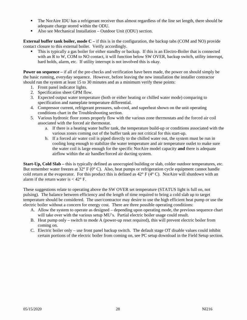
The NorAire IDU has a refrigerant receiver thus almost regardless of the line set length, there should be adequate charge stored within the ODU.
Also see Mechanical Installation – Outdoor Unit (ODU) section. External buffer tank boiler, mode C – if this is in the configuration, the backup tabs (COM and NO) provide contact closure to this external boiler. Verify accordingly. This is typically a gas boiler for either standby or backup. If this is an Electro-Boiler that is connected
with an R to W, COM to NO contact, it will function below SW OVER, backup switch, utility interrupt, hard holds, alarm, etc. If utility interrupt is not involved this is okay.
Power on sequence – if all of the pre-checks and verification have been made, the power on should simply be the basic running, everyday sequence. However, before leaving the new installation the installer contractor should run the system at least 15 to 30 minutes and as a minimum verify these points:
1. Front panel indicator lights. 2. Specification sheet GPM flow. 3. Expected output water temperature (both or either heating or chilled water mode) comparing to
specification and nameplate temperature differential. 4. Compressor current, refrigerant pressures, sub-cool, and superheat shown on the unit operating
conditions chart in the Troubleshooting section. 5. Various hydronic floor zones properly flow with the various zone thermostats and the forced air coil
associated with the forced air thermostat. a. If there is a heating water buffer tank, the temperature build-up or conditions associated with the
various zones coming out of the buffer tank are not critical for this start-up. b. If a forced air water coil is piped directly to the chilled water out, the system must be run in
cooling long enough to stabilize the water temperature and air temperature outlet to make sure the water coil is large enough for the specific NorAire model capacity and there is adequate airflow within the air handler/forced air ducting system.
Start-Up, Cold Slab – this is typically defined as unoccupied building or slab, colder outdoor temperatures, etc. But remember water freezes at 32° F (0° C). Also, heat pumps or refrigeration cycle equipment cannot handle cold return at the evaporator. For this product this is defined as 42° F (4° C). NorAire will shutdown with an alarm if the return water is < 42° F. These suggestions relate to operating above the SW OVER set temperature (STATUS light is full on, not pulsing). The balance between efficiency and the length of time required to bring a cold slab up to target temperature should be considered. The user/contractor may desire to use the high efficient heat pump or use the electric boiler without a concern for energy cost. There are three possible operating conditions:
A. Allow the system to operate as designed – depending upon operating mode, the previous sequence chart will take over with the various setup MU’s. Partial electric boiler usage could result.
B. Heat pump only – switch to mode A (power-up reset required), this will prevent electric boiler from coming on.
C. Electric boiler only – use front panel backup switch. The default stage OT disable values could inhibit certain portions of the electric boiler from coming on, see PC setup download in the Field Setup section.
05/15/2020 29 NI216
Preventative Maintenance
IDU front panel, SERVICE light – the warning light should never appear and if it does preventative action should be initiated. The front decal references a number relating to a condition. The LED light will count out a number providing an indication of a controller diagnostic testing. It is the user’s responsibility to contact the installer or proper servicing contractor with this warning condition for proper servicing or system installation update. Repeated warning shutdown may reduce the necessary heat or cool capacity, make the unit very inefficient, and will shorten the life of this heat pump system. Hydronic system loop pressure – the system must be maintained between 10 and 25 psig at all times. Below 10 psi there is potential for the internal pump to cavitate and become blocked. At 30 psig the safety relief could open. Refrigerant liquid line filter/dryer – should only be replaced if there is a pump out or opening within the refrigeration system. Suggest mandatory replacement whenever refrigerant system is opened or component changes. Outdoor unit fan – for all operating seasons and conditions the ODU discharge fan must be free to circulate the required amount of air. ODU heat exchanger fins – the coil fins around the peripheral of the ODU must be clean and open for proper airflow to generate IDU heat or cool energy. Periodic inspection and observation is required to make sure outdoor debris or dirt does not starve the unit’s ability to draw fresh and clean outdoor air.
05/15/2020 30 NI216
Troubleshooting Comment – this section assumes the service technician is recently familiar with all sections or pages of this installation and operating manual up through this page. To emphasize only a few, there are many installation and operating items detailed which could affect the system and if not initially done correctly could bring the service technician to this page. Correct system installation design, piping, water flow, Btu/h absorption of the various components, air
handler CFM, etc. Correct water fill and purge Electrical hookup Field setup Start-up suggestions
System logic description – the Control Sequence Information section provides considerable information on the characteristics of this controller. Correct field setup or programming, water flow, and approximate correct outdoor temperature reading become key to most of these sequences. Various voltage checks – it’s always helpful to check various key voltage points. The externals of this NorAire controller follow HVAC terminology and basic design concept. The controller 5V power supply can be checked at the sensor terminal block Red to C. Anti-cycle delay (ACD) – see Control Sequence section, relates action at the end of ACD. Option PC software CD and provided USB cable – see Start-Up section. This can be a very valuable diagnostic tool plus it allows the opportunity for changing some of the delay times to shorten testing wait times. Notice the warning paragraph, must return default values Properly evaluate boiler staging OT disables Alt-A history could be a valuable piece of information. At the beginning of each ACD (green power
light blinking) the reason for triggering ACD is written out on a pull-down screen. This will show the history of the last five ACD’s, the first is written over for a rotating list of five.
Hint, testing the control board by itself could be very difficult – powering up the board and providing stat W or Y input will trigger a series of sequences which will require external limit or temperature sensor information. Without these proper connections and external components, the board will go into various error or alarm modes. Flow sensor RT temp sensor – compressor no response, low water flow STc temp sensor – ODT mode error, compressor no response, low water flow OT temp sensor – within reasonable range
Temperature sensor sequence usage: RT – low flow, tank changeover, GPM calculation STc – freeze, low flow, ODU mode, cool limit, heat limit STh – Electro-Boiler target
Bad temperature sensor, power on LED – software detected no value, cannot detect incorrect value. This green LED blinks indicating which sensor. RT – one blink every 2 seconds 44° F (1° C) STh (above boiler) – two blinks every 2 seconds 110° F (43° C) OT – three blinks every two seconds OT mid value minus 4° F (2° C) STc (heat exchanger out) – four blinks every 2 seconds 44° F (1° C) Bad sensor forced default value – the above right column number
Nuisance service LED low flow or alarm compressor no response LED – both of these sequence temperature calculations can be disabled with PC setup software. Entering a 0 digit cancels these sequence tests.
05/15/2020 31 NI216
Internal pump – the normal operation of the pump is from a W or Y IN and defrost control wire. The pump is on for 30 seconds to stabilize various temperature sensors before HP-Y output. Also, the pump continues for 60 seconds after W or Y IN is dropped. A hardware tab labeled PUMP (T6) activates the pump relay when this tab is jumpered to R voltage.
SW OVER setup dial switch – typically do not use positions 7 or 0. See Field Setup section.
Backup or auxiliary electric – this is active for OT temperatures below SW OVER setting, front panel backup switch, mode sequence charts, and Hard Hold. The continued heating provisions include: Mode A – not possible Mode B – internal Electro-Boiler Mode C – possible external boiler plumbed at a buffer tank and activated by NorAire control board
backup, COM, and NO tabs
Comment – except for no flow sensing, there are no other backup SERVICE or ALARM limits. The Electro-Boiler has its own target temperature/modulation, auto reset hi-limit, and manual reset hi-limit installed at the boiler vessel. It is assumed the external boiler will have its own temperature control and limits.
Front panel and control board LED’s – the Operation Indicators section with the various LED’s will provide significant diagnostic information. The NorAire controller (with the PC software CD) provides more than typical HVAC products. Some additional tips associated with the Operation Indicators page: POWER ON also provides bad sensor information. This is not an all exclusive bad sensor diagnostic. It
simply means software cannot detect a value, see below. It does not diagnose an incorrect value. HP ODU or AQUASTAT – this represents a hardware voltage, the same as taking a voltage reading on
HP-Y screw, W screw, or Y screw. This is handy knowing the primary externals coming in and out of the control board.
STATUS – this indicates the software mode, it displays the condition without consideration for W, Y, or Utility Interrupt inputs. Also, fast pulsing with the same power-on pulsing means the mode switch is in D position, which is not used.
SERVICE – reference the factory default setup limits. Low water flow is calculated 5 minutes after each new W-IN. It does not repeat, but there is an initial cycle off and on, with the service light indicating this condition.
ALARM – this could lead to a Hard Hold, see Control Sequence Information section. - FREEZE PROTECT, count 1 – this is critical, at 38° F (3° C) coming out of the coax heat
exchanger, to make sure the heat exchanger does not freeze and bust. Warranty does not cover leaking or busted heat exchanger.
- COMPRESSOR NO RESPONSE, count 2 – this is critical for preventing building freeze-up and automatic backup. Two detection methods are employed: Hardware, ODU fault wire (continuous) – this should be connected to E-tab and PC
download “compressor no response diff” should have digit “0” entry. Internal sequence calculation – during a W or Y input, every 5 minutes the supply
temperature (STc) is compared to return temperature (RT). The PC download has a selected difference value, if the supply to return relationship is less than this value the control board sequence assumes the ODU is “dead”.
Comment – in order to prevent the ODU from continually resetting, the HP-Y is not dropped during the IDU internal alarm retry sequences.
- Return < 42° F, count 3 – this is an internal test at the hydronic return water sensor, 20 seconds after outputting HP-Y1. A shutdown and alarm is declared for water too cold coming into the heat pump evaporator coil. Refrigerant low pressure danger and possible low pressure cutout could result if the compressor suction is too low. This test and monitor prevent damage to compressor.
- NO WATER FLOW, count 4 – this is a direct result of the water inlet pipe hardware safety flow switch. There is a 20-second delay after pump start (W or Y IN). See Control Sequence section.
Comment – if mode B or C and a declared Hard Hold, the backup internal boiler or external backup contact closure responds to a W IN.
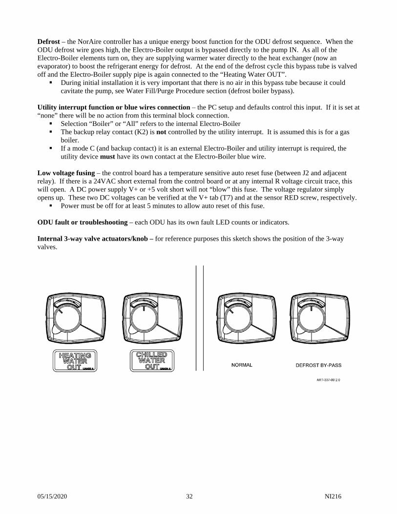
05/15/2020 32 NI216
Defrost – the NorAire controller has a unique energy boost function for the ODU defrost sequence. When the ODU defrost wire goes high, the Electro-Boiler output is bypassed directly to the pump IN. As all of the Electro-Boiler elements turn on, they are supplying warmer water directly to the heat exchanger (now an evaporator) to boost the refrigerant energy for defrost. At the end of the defrost cycle this bypass tube is valved off and the Electro-Boiler supply pipe is again connected to the “Heating Water OUT”. During initial installation it is very important that there is no air in this bypass tube because it could
cavitate the pump, see Water Fill/Purge Procedure section (defrost boiler bypass). Utility interrupt function or blue wires connection – the PC setup and defaults control this input. If it is set at “none” there will be no action from this terminal block connection. Selection “Boiler” or “All” refers to the internal Electro-Boiler The backup relay contact (K2) is not controlled by the utility interrupt. It is assumed this is for a gas
boiler. If a mode C (and backup contact) it is an external Electro-Boiler and utility interrupt is required, the
utility device must have its own contact at the Electro-Boiler blue wire. Low voltage fusing – the control board has a temperature sensitive auto reset fuse (between J2 and adjacent relay). If there is a 24VAC short external from the control board or at any internal R voltage circuit trace, this will open. A DC power supply V+ or +5 volt short will not “blow” this fuse. The voltage regulator simply opens up. These two DC voltages can be verified at the V+ tab (T7) and at the sensor RED screw, respectively. Power must be off for at least 5 minutes to allow auto reset of this fuse.
ODU fault or troubleshooting – each ODU has its own fault LED counts or indicators. Internal 3-way valve actuators/knob – for reference purposes this sketch shows the position of the 3-way valves.
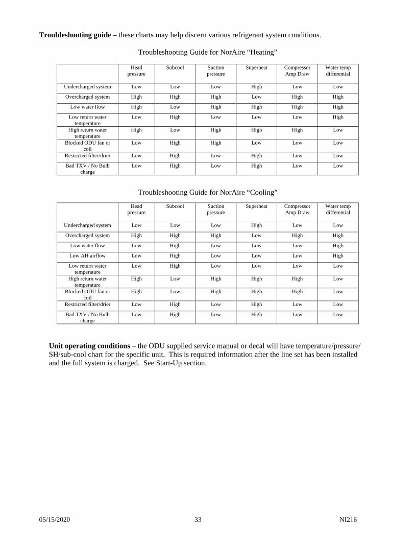
05/15/2020 33 NI216
Troubleshooting guide – these charts may help discern various refrigerant system conditions.
Troubleshooting Guide for NorAire “Heating”
Head pressure
Subcool Suction pressure
Superheat Compressor Amp Draw
Water temp differential
Undercharged system Low Low Low High Low Low
Overcharged system High High High Low High High
Low water flow High Low High High High High
Low return water temperature
Low High Low Low Low High
High return water temperature
High Low High High High Low
Blocked ODU fan or coil
Low High High Low Low Low
Restricted filter/drier Low High Low High Low Low
Bad TXV / No Bulb charge
Low High Low High Low Low
Troubleshooting Guide for NorAire “Cooling”
Head pressure
Subcool Suction pressure
Superheat Compressor Amp Draw
Water temp differential
Undercharged system Low Low Low High Low Low
Overcharged system High High High Low High High
Low water flow Low High Low Low Low High
Low AH airflow Low High Low Low Low High
Low return water temperature
Low High Low Low Low Low
High return water temperature
High Low High High High Low
Blocked ODU fan or coil
High Low High High High Low
Restricted filter/drier Low High Low High Low Low
Bad TXV / No Bulb charge
Low High Low High Low Low
Unit operating conditions – the ODU supplied service manual or decal will have temperature/pressure/ SH/sub-cool chart for the specific unit. This is required information after the line set has been installed and the full system is charged. See Start-Up section.
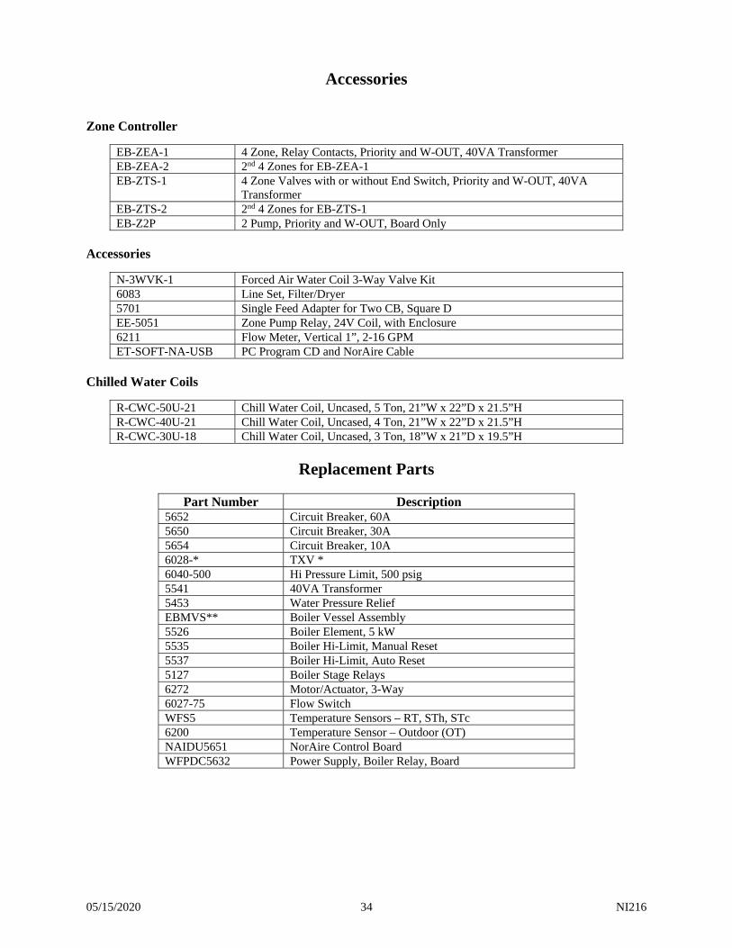
05/15/2020 34 NI216
Accessories Zone Controller
EB-ZEA-1 4 Zone, Relay Contacts, Priority and W-OUT, 40VA Transformer EB-ZEA-2 2nd 4 Zones for EB-ZEA-1 EB-ZTS-1 4 Zone Valves with or without End Switch, Priority and W-OUT, 40VA
Transformer EB-ZTS-2 2nd 4 Zones for EB-ZTS-1 EB-Z2P 2 Pump, Priority and W-OUT, Board Only
Accessories
N-3WVK-1 Forced Air Water Coil 3-Way Valve Kit 6083 Line Set, Filter/Dryer 5701 Single Feed Adapter for Two CB, Square D EE-5051 Zone Pump Relay, 24V Coil, with Enclosure 6211 Flow Meter, Vertical 1”, 2-16 GPM ET-SOFT-NA-USB PC Program CD and NorAire Cable
Chilled Water Coils
R-CWC-50U-21 Chill Water Coil, Uncased, 5 Ton, 21”W x 22”D x 21.5”H R-CWC-40U-21 Chill Water Coil, Uncased, 4 Ton, 21”W x 22”D x 21.5”H R-CWC-30U-18 Chill Water Coil, Uncased, 3 Ton, 18”W x 21”D x 19.5”H
Replacement Parts
Part Number Description 5652 Circuit Breaker, 60A 5650 Circuit Breaker, 30A 5654 Circuit Breaker, 10A 6028-* TXV * 6040-500 Hi Pressure Limit, 500 psig 5541 40VA Transformer 5453 Water Pressure Relief EBMVS** Boiler Vessel Assembly 5526 Boiler Element, 5 kW 5535 Boiler Hi-Limit, Manual Reset 5537 Boiler Hi-Limit, Auto Reset 5127 Boiler Stage Relays 6272 Motor/Actuator, 3-Way 6027-75 Flow Switch WFS5 Temperature Sensors – RT, STh, STc 6200 Temperature Sensor – Outdoor (OT) NAIDU5651 NorAire Control Board WFPDC5632 Power Supply, Boiler Relay, Board
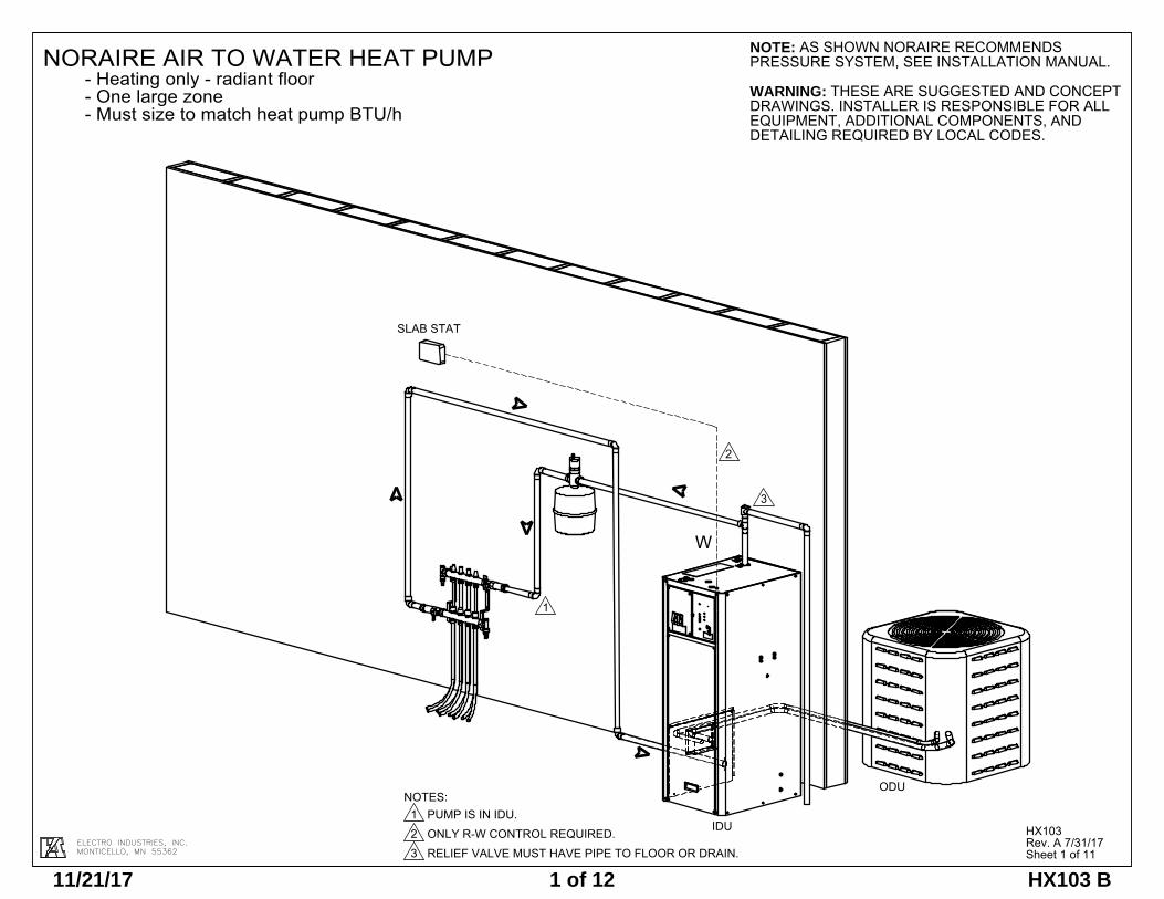
ELECTRO INDUSTRIES, INC.MONTICELLO, MN 55362
NORAIRE AIR TO WATER HEAT PUMP- Heating only - radiant floor- One large zone- Must size to match heat pump BTU/h
HX103Rev. A 7/31/17Sheet 1 of 11
SLAB STAT
IDU
ODU
W
2
1
3
2 RELIEF VALVE MUST HAVE PIPE TO FLOOR OR DRAIN. ONLY R-W CONTROL REQUIRED.
DETAILING REQUIRED BY LOCAL CODES.
3
EQUIPMENT, ADDITIONAL COMPONENTS, AND
NOTES:1 PUMP IS IN IDU.
NOTE: AS SHOWN NORAIRE RECOMMENDS PRESSURE SYSTEM, SEE INSTALLATION MANUAL.
WARNING: THESE ARE SUGGESTED AND CONCEPT DRAWINGS. INSTALLER IS RESPONSIBLE FOR ALL
11/21/17 1 of 12 HX103 B
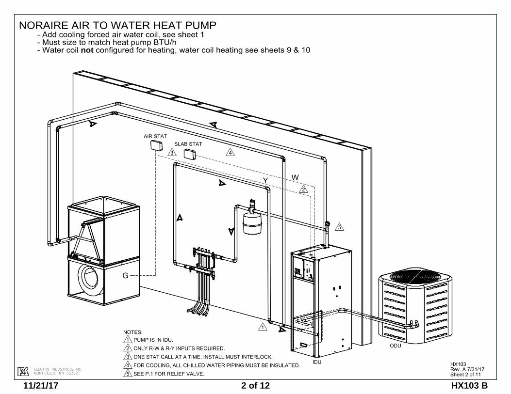
ELECTRO INDUSTRIES, INC.MONTICELLO, MN 55362
NORAIRE AIR TO WATER HEAT PUMP- Add cooling forced air water coil, see sheet 1- Must size to match heat pump BTU/h- Water coil not configured for heating, water coil heating see sheets 9 & 10
HX103Rev. A 7/31/17Sheet 2 of 11
SLAB STAT
IDU
ODU
2
1
AIR STAT
WY
G
3 4
5
NOTES:1 PUMP IS IN IDU.2 ONLY R-W & R-Y INPUTS REQUIRED.3 ONE STAT CALL AT A TIME, INSTALL MUST INTERLOCK.4 FOR COOLING, ALL CHILLED WATER PIPING MUST BE INSULATED.5 SEE P.1 FOR RELIEF VALVE.
11/21/17 2 of 12 HX103 B
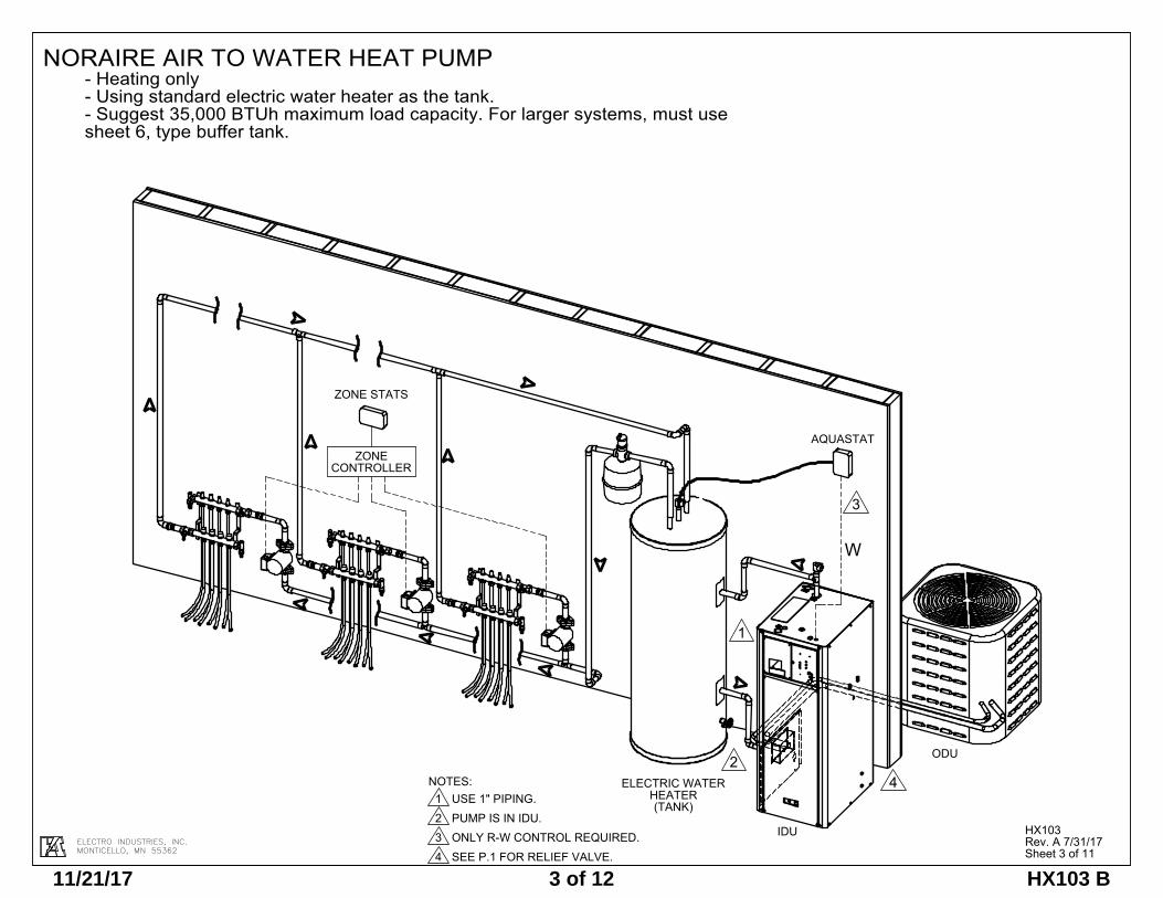
ELECTRO INDUSTRIES, INC.MONTICELLO, MN 55362
NOTES:1 USE 1" PIPING.2 PUMP IS IN IDU.3 ONLY R-W CONTROL REQUIRED.4 SEE P.1 FOR RELIEF VALVE.
ELECTRIC WATER HEATER(TANK)
IDU
1
AQUASTAT
W
2
ZONE STATS
ZONE CONTROLLER
ODU
3
4
NORAIRE AIR TO WATER HEAT PUMP- Heating only- Using standard electric water heater as the tank.- Suggest 35,000 BTUh maximum load capacity. For larger systems, must use sheet 6, type buffer tank.
HX103Rev. A 7/31/17Sheet 3 of 11
11/21/17 3 of 12 HX103 B
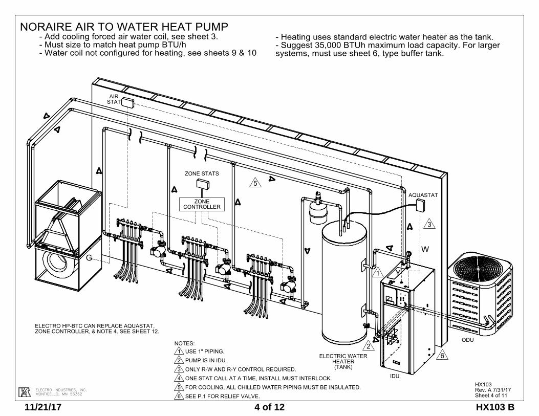
ELECTRO INDUSTRIES, INC.MONTICELLO, MN 55362
NORAIRE AIR TO WATER HEAT PUMP- Add cooling forced air water coil, see sheet 3.- Must size to match heat pump BTU/h- Water coil not configured for heating, see sheets 9 & 10
- Heating uses standard electric water heater as the tank.- Suggest 35,000 BTUh maximum load capacity. For larger systems, must use sheet 6, type buffer tank.
HX103Rev. A 7/31/17Sheet 4 of 11
ELECTRIC WATER HEATER(TANK)
IDU
1
AQUASTAT
W
2
ZONE STATS
ZONE CONTROLLER
ODU
3
ELECTRO HP-BTC CAN REPLACE AQUASTAT, ZONE CONTROLLER, & NOTE 4. SEE SHEET 12.
G
Y
AIRSTAT
5
6
NOTES:1 USE 1" PIPING.2 PUMP IS IN IDU.3 ONLY R-W AND R-Y CONTROL REQUIRED.4 ONE STAT CALL AT A TIME, INSTALL MUST INTERLOCK.5 FOR COOLING, ALL CHILLED WATER PIPING MUST BE INSULATED.6 SEE P.1 FOR RELIEF VALVE.
11/21/17 4 of 12 HX103 B
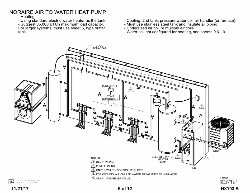
ELECTRO INDUSTRIES, INC.MONTICELLO, MN 55362
ELECTRIC WATER HEATER(TANK)
IDU
1
W
2
ZONE STATS
ZONE CONTROLLER
ODU
3
COOL AQUASTAT
Y
Rev A Remove note:ELECTRO HP-BTC CAN REPLACE AQUASTAT, ZONE CONTROLLER, & NOTE 4. SEE SHEET 12.Remove btc note 4
4
5NOTES:1 USE 1" PIPING.2 PUMP IS IN IDU.3 ONLY R-W & R-Y CONTROL REQUIRED.4 FOR COOLING, ALL CHILLED WATER PIPING MUST BE INSULATED.5 SEE P.1 FOR RELIEF VALVE.
NORAIRE AIR TO WATER HEAT PUMP- Heating- Using standard electric water heater as the tank.- Suggest 35,000 BTUh maximum load capacity. For larger systems, must use sheet 6, type buffer tank.
HX103Rev. A 7/31/17Sheet 5 of 11
- Cooling, 2nd tank, pressure water coil air handler (or furnace).- Must use stainless steel tank and insulate all piping- Undersized air coil or multiple air coils- Water coil not configured for heating, see sheets 9 & 10
11/21/17 5 of 12 HX103 B
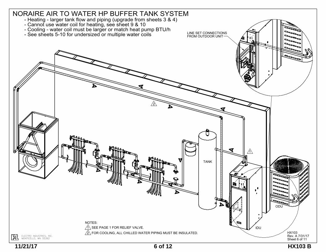
ELECTRO INDUSTRIES, INC.MONTICELLO, MN 55362
1
TANK
IDU
ODU
2
LINE SET CONNECTIONSFROM OUTDOOR UNIT
NOTES:1 SEE PAGE 1 FOR RELIEF VALVE.2 FOR COOLING, ALL CHILLED WATER PIPING MUST BE INSULATED.
Rev A remove notes:Suggest using HP-BTC, see sheet 12and HP-BTC can service 8 zonesRemove BTC note 3
NORAIRE AIR TO WATER HP BUFFER TANK SYSTEM- Heating - larger tank flow and piping (upgrade from sheets 3 & 4)- Cannot use water coil for heating, see sheet 9 & 10- Cooling - water coil must be larger or match heat pump BTU/h- See sheets 5-10 for undersized or multiple water coils
HX103Rev. A 7/31/17Sheet 6 of 11
11/21/17 6 of 12 HX103 B
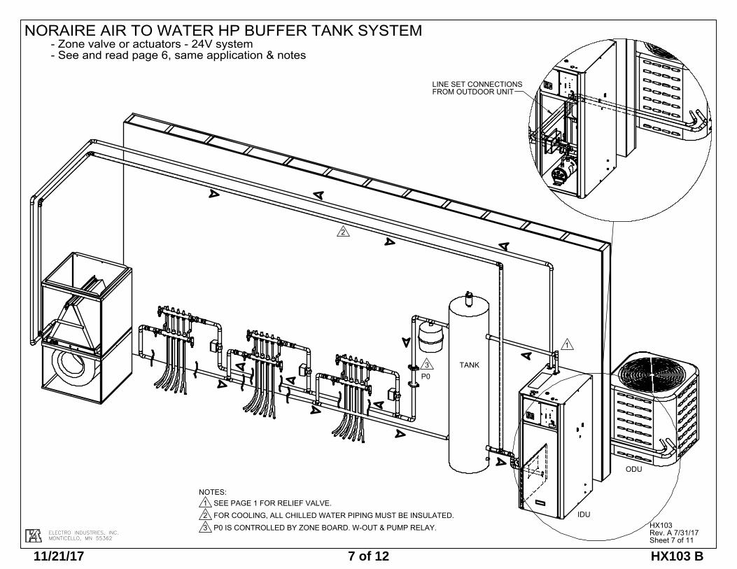
ELECTRO INDUSTRIES, INC.MONTICELLO, MN 55362
1
TANK
IDU
ODU
2
NOTES:1 SEE PAGE 1 FOR RELIEF VALVE.2 FOR COOLING, ALL CHILLED WATER PIPING MUST BE INSULATED.3 P0 IS CONTROLLED BY ZONE BOARD. W-OUT & PUMP RELAY.
P03
LINE SET CONNECTIONSFROM OUTDOOR UNIT
Rev 10 remove note: Suggest HP-BTC-24 and picture of HP-BTC-24
HX103Rev. A 7/31/17Sheet 7 of 11
NORAIRE AIR TO WATER HP BUFFER TANK SYSTEM- Zone valve or actuators - 24V system- See and read page 6, same application & notes
11/21/17 7 of 12 HX103 B
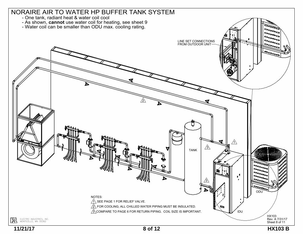
ELECTRO INDUSTRIES, INC.MONTICELLO, MN 55362
1
TANK
IDU
ODU
2
NOTES:1 SEE PAGE 1 FOR RELIEF VALVE.2 FOR COOLING, ALL CHILLED WATER PIPING MUST BE INSULATED.3 COMPARE TO PAGE 6 FOR RETURN PIPING. COIL SIZE IS IMPORTANT.
3
3
LINE SET CONNECTIONSFROM OUTDOOR UNIT
HX103Rev. A 7/31/17Sheet 8 of 11
NORAIRE AIR TO WATER HP BUFFER TANK SYSTEM- One tank, radiant heat & water coil cool- As shown, cannot use water coil for heating, see sheet 9- Water coil can be smaller than ODU max. cooling rating.
REV 10: remove HP-BTC notess and picture
11/21/17 8 of 12 HX103 B
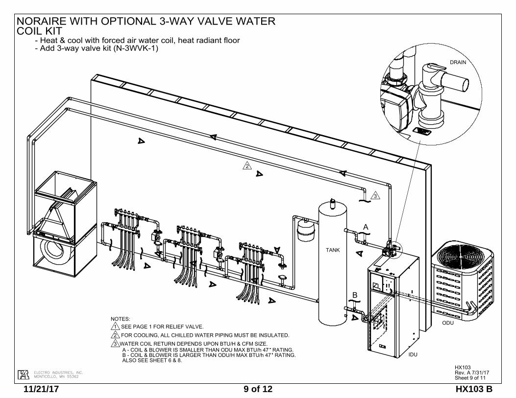
ELECTRO INDUSTRIES, INC.MONTICELLO, MN 55362
TANK
IDU
ODU
2
B
A
DRAIN
3
NOTES:1 SEE PAGE 1 FOR RELIEF VALVE.2 FOR COOLING, ALL CHILLED WATER PIPING MUST BE INSULATED.3 WATER COIL RETURN DEPENDS UPON BTU/H & CFM SIZE.
A - COIL & BLOWER IS SMALLER THAN ODU MAX BTU/h 47 RATING. B - COIL & BLOWER IS LARGER THAN ODU/H MAX BTU/h 47 RATING. ALSO SEE SHEET 6 & 8.
Rev 10: Remove HP-BTC notes and picture
NORAIRE WITH OPTIONAL 3-WAY VALVE WATER COIL KIT
- Heat & cool with forced air water coil, heat radiant floor- Add 3-way valve kit (N-3WVK-1)
HX103Rev. A 7/31/17Sheet 9 of 11
11/21/17 9 of 12 HX103 B
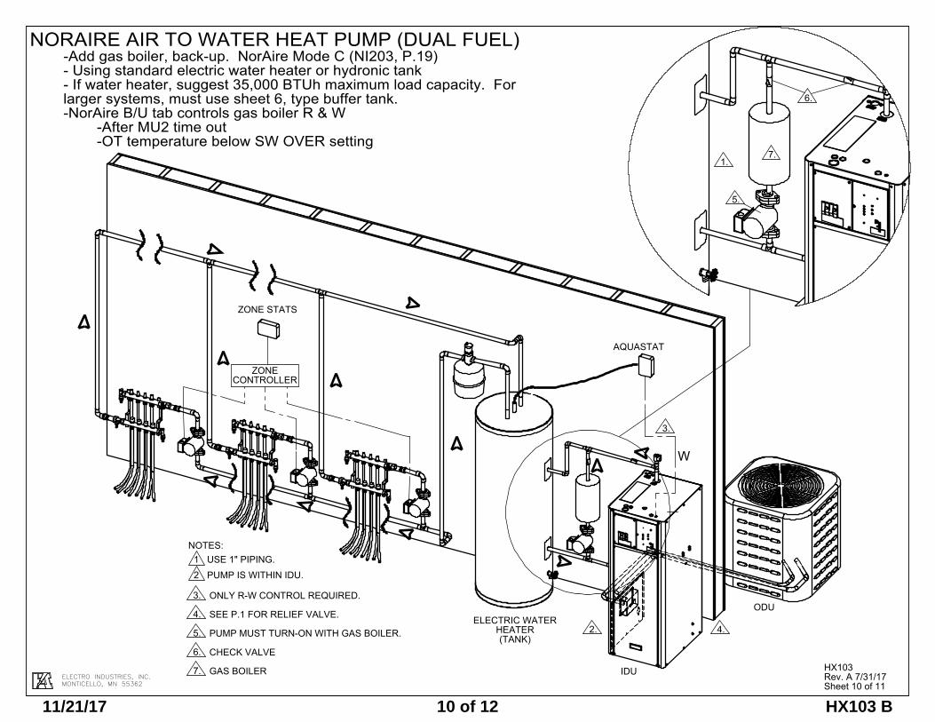
ELECTRO INDUSTRIES, INC.MONTICELLO, MN 55362
NORAIRE AIR TO WATER HEAT PUMP (DUAL FUEL)-Add gas boiler, back-up. NorAire Mode C (NI203, P.19)- Using standard electric water heater or hydronic tank- If water heater, suggest 35,000 BTUh maximum load capacity. For larger systems, must use sheet 6, type buffer tank.-NorAire B/U tab controls gas boiler R & W
-After MU2 time out-OT temperature below SW OVER setting
HX103Rev. A 7/31/17Sheet 10 of 11
5.
6.
7.1.
4.
AQUASTAT
3.
W
ODU
IDU
2.ELECTRIC WATER
HEATER(TANK)
ZONECONTROLLER
ZONE STATS
NOTES:1 USE 1" PIPING.2 PUMP IS WITHIN IDU.
3. ONLY R-W CONTROL REQUIRED.
4. SEE P.1 FOR RELIEF VALVE.
5. PUMP MUST TURN-ON WITH GAS BOILER.
6. CHECK VALVE
7. GAS BOILER
11/21/17 10 of 12 HX103 B
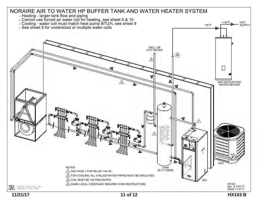
ELECTRO INDUSTRIES, INC.MONTICELLO, MN 55362
NORAIRE AIR TO WATER HP BUFFER TANK AND WATER HEATER SYSTEM- Heating - larger tank flow and piping- Cannot use forced air water coil for heating, see sheet 9 & 10- Cooling - water coil must match heat pump BTU/h, see sheet 9- See sheet 5 for undersized or multiple water coils
Sheet 11 of 11
HX103Rev. A 7/31/17
NOTES:1 SEE PAGE 1 FOR RELIEF VALVE.2 FOR COOLING, ALL CHILLED WATER PIPING MUST BE INSULATED.3 COIL MUST BE 150 PSIG RATED.4 SOME LOCAL CODES MAY REQUIRE FLOW RESTRUCTURE.
~90
WATER HEATERGAS OR ELECTRIC
SUPPLYFHOT~130 F
WELL OR CITY WATER
3
IDU
ODU
2
(R-17 LINER)TANK
A4
1
11/21/17 11 of 12 HX103 B
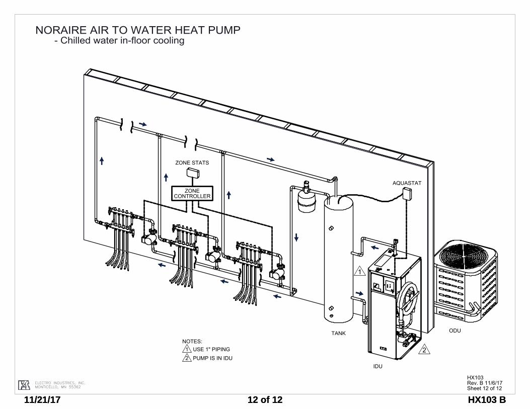
ELECTRO INDUSTRIES, INC.MONTICELLO, MN 55362
TANK
IDU
1
AQUASTAT
2
ZONE STATS
ZONE CONTROLLER
ODU
NOTES:1 USE 1" PIPING2 PUMP IS IN IDU
NORAIRE AIR TO WATER HEAT PUMP- Chilled water in-floor cooling
HX103Rev. B 11/6/17Sheet 12 of 12
11/21/17 12 of 12 HX103 B11/21/17 12 of 12 HX103 B
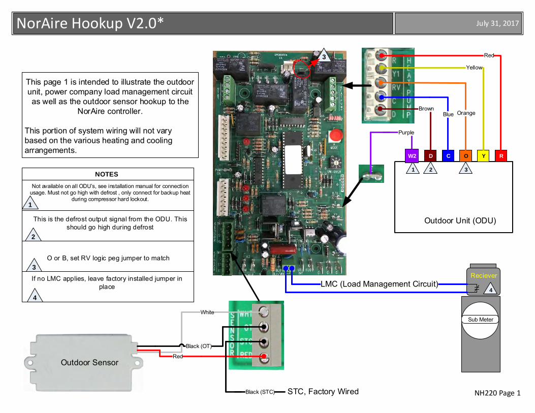
NH220 Page 1
July 31, 2017NorAire Hookup V2.0*
NOTES
This is the defrost output signal from the ODU. This should go high during defrost
1
Not available on all ODU’s, see installation manual for connection usage. Must not go high with defrost , only connect for backup heat
during compressor hard lockout.
O or B, set RV logic peg jumper to match
2
3
4
If no LMC applies, leave factory installed jumper in place
This page 1 is intended to illustrate the outdoor unit, power company load management circuit as well as the outdoor sensor hookup to the
NorAire controller.
This portion of system wiring will not vary based on the various heating and cooling arrangements.
Outdoor Sensor
Outdoor Unit (ODU)
RC YOD
Purple
1 2 3
Yellow
OrangeBlueBrown
Sub Meter
Reciever
4
W2
STC, Factory Wired
White
Black (OT)
Black (STC)
Red
Red3
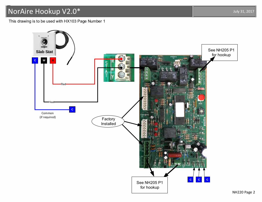
NH220 Page 2
July 31, 2017NorAire Hookup V2.0*
Slab Stat
C
C C C
Factory Installed
RWC
Red
Heat
See NH205 P1 for hookup
See NH205 P1 for hookup
This drawing is to be used with HX103 Page Number 1
Common(if required)
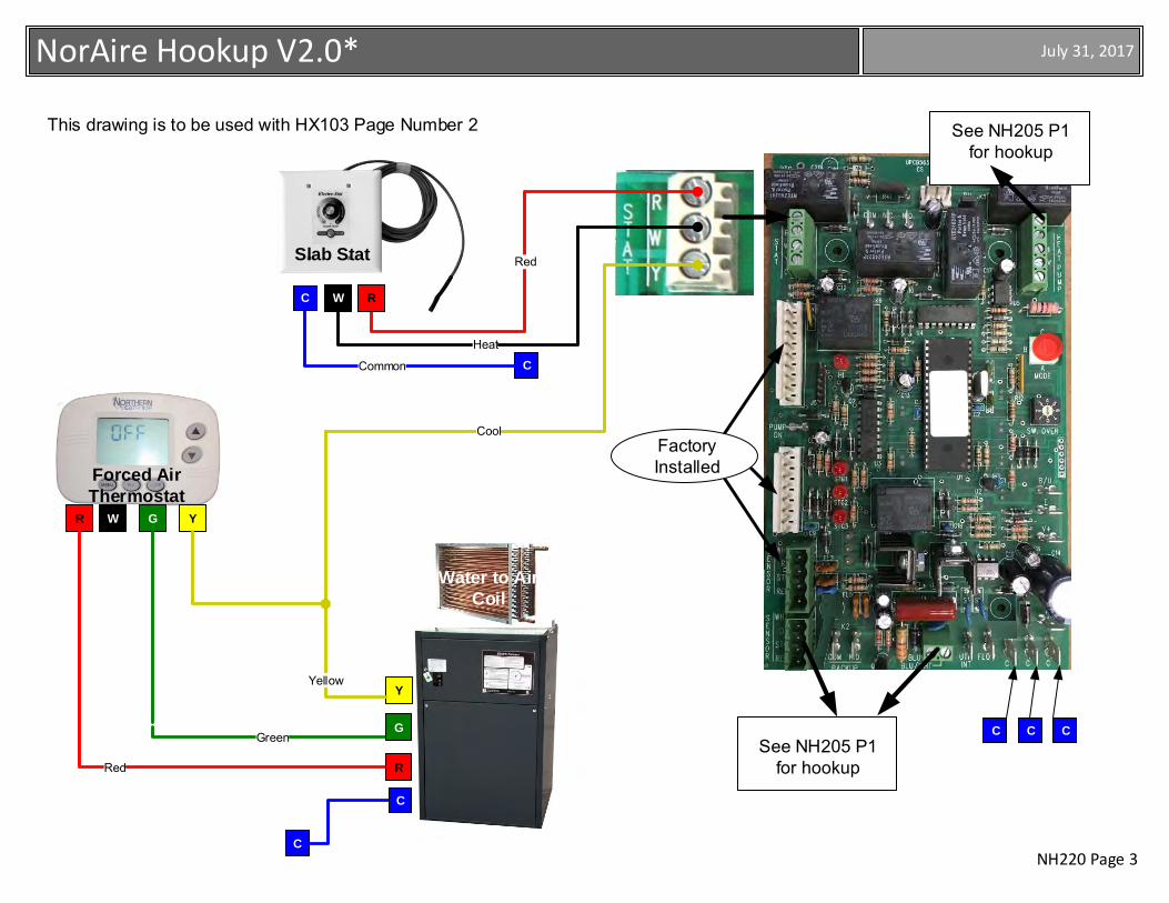
NH220 Page 3
July 31, 2017NorAire Hookup V2.0*
This drawing is to be used with HX103 Page Number 2
Slab Stat Red
Heat
Forced Air Thermostat
R W G Y
C C C
Factory Installed
CCommon
C
Air HandlerAir Handler
Water to Air Coil
See NH205 P1 for hookup
See NH205 P1 for hookup
RWC
Cool
Green
Red R
G
C
YYellow
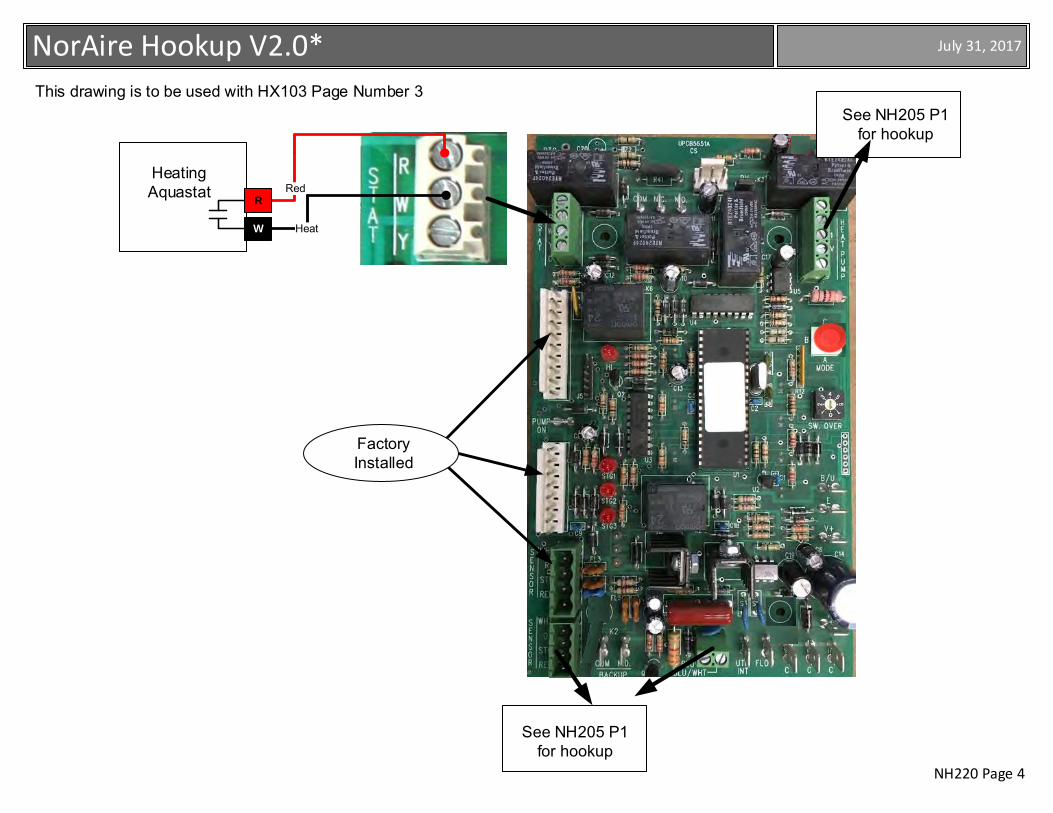
NH220 Page 4
July 31, 2017NorAire Hookup V2.0*
Factory Installed
RedHeatingAquastat
R
W Heat
This drawing is to be used with HX103 Page Number 3See NH205 P1
for hookup
See NH205 P1 for hookup
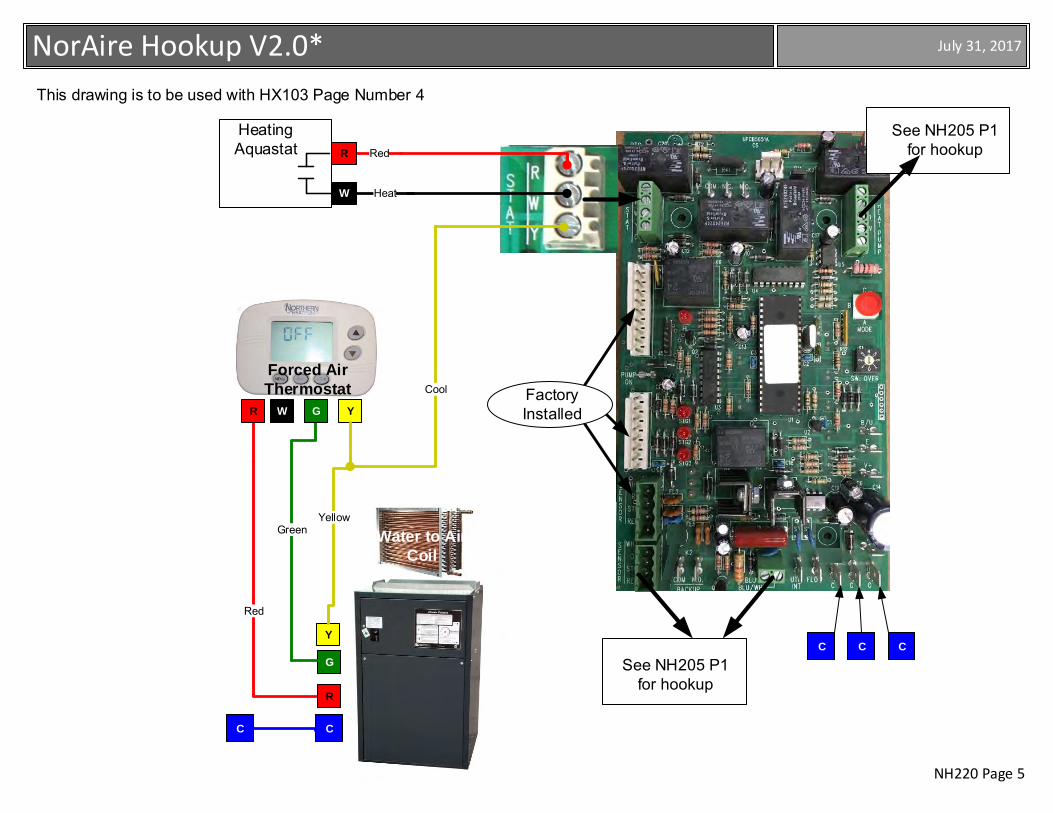
NH220 Page 5
July 31, 2017NorAire Hookup V2.0*
Red
Heat
Cool Factory Installed
Red
Green
R
W
Forced Air Thermostat
R W G Y
C C C
C
R
G
C
Air HandlerAir Handler
Water to Air Coil
Heating Aquastat
Y
Yellow
See NH205 P1 for hookup
See NH205 P1 for hookup
This drawing is to be used with HX103 Page Number 4
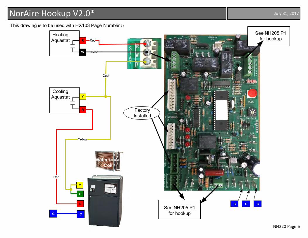
NH220 Page 6
July 31, 2017NorAire Hookup V2.0*
Red
Heat
Y
Cool
Factory Installed
Air Handler
Red
Yellow
Heating Aquastat
R
W
Heating Aquastat
R
Cooling Aquastat
C
C C C
Air HandlerAir Handler
Water to Air Coil
R
G
C
This drawing is to be used with HX103 Page Number 5
Y
See NH205 P1 for hookup
See NH205 P1 for hookup
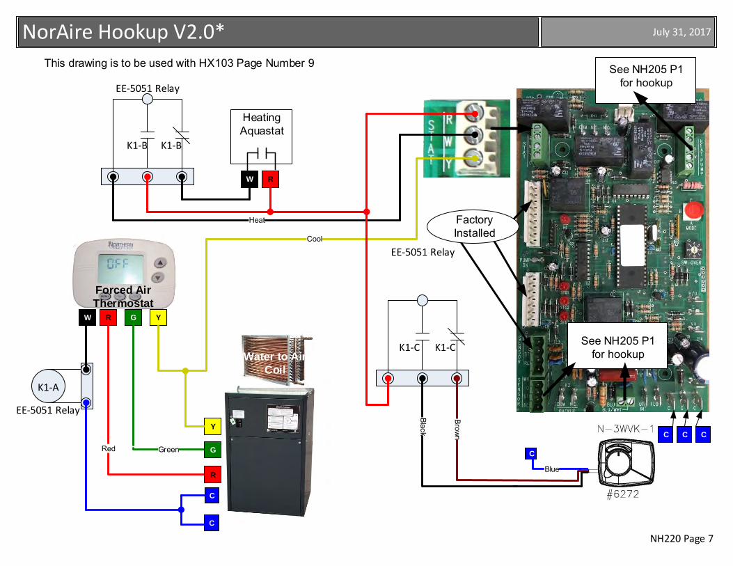
NH220 Page 7
July 31, 2017NorAire Hookup V2.0*
EE-5051 Relay
EE-5051 Relay
EE-5051 Relay
K1-C K1-C
K1-B K1-B
This drawing is to be used with HX103 Page Number 9
C
Blue
Forced Air Thermostat
RW G Y
C C C
Factory Installed
C
Air HandlerAir Handler
Water to Air Coil
See NH205 P1 for hookup
See NH205 P1 for hookup
RW
Cool
GreenRed
R
G
C
Y
Heating Aquastat
K1-A
Heat
Brown
Black
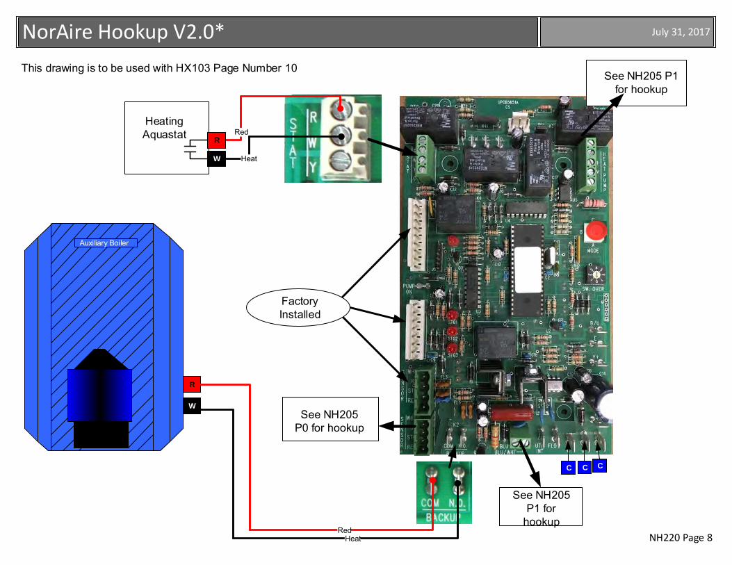
NH220 Page 8
July 31, 2017NorAire Hookup V2.0*
This drawing is to be used with HX103 Page Number 10
See NH205 P1 for
hookup
Factory Installed
RedHeatingAquastat
R
W Heat
See NH205 P0 for hookup
See NH205 P1 for hookup
Auxiliary Boiler
C C C
R
W
RedHeat
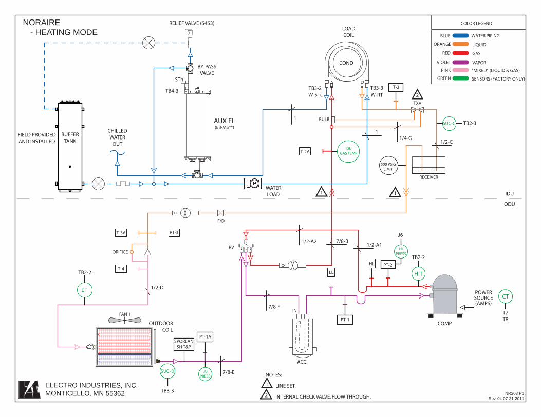
TXV
1/4-G
7/8-E
1/2-D
1/2-C
1/2-A11/2-A2
7/8-F
OUTDOORCOIL
7/8-B
1
1
COMP
F/D
LL
HL
BULB
T-3A
PT-1A
PT-1
PT-2T-4
PT-3
T-2A
RV
POWERSOURCE(AMPS)
HIT
HIPRESS
ACC
FAN 1
CT
SUC-C
SPORLAN5H T&P
IDUGAS TEMP
IDU
ODU
ORIFICE
LOPRESS
500 PSIGLIMIT
RECEIVER
T-3
NR203 P1Rev. 04 07-21-2011
NORAIRE- HEATING MODE
WATERLOAD
LOADCOIL
COND
TB3-3TB3-2
IN
AUX EL(EB-MS**)
STh
T7T8
TB2-2
J6
TB2-3
TB3-3
TB2-2
W-STc W-RT
BUFFERTANK
BY-PASSVALVE
RELIEF VALVE (5453)
ELECTRO INDUSTRIES, INC.MONTICELLO, MN 55362
FIELD PROVIDEDAND INSTALLED
CHILLEDWATER
OUT
P
COLOR LEGEND
BLUE WATER PIPING
ORANGE LIQUID
RED GAS
VIOLET VAPOR
PINK “MIXED” (LIQUID & GAS)
GREEN SENSORS (FACTORY ONLY)
NOTES:
1 LINE SET.
1 1
2 INTERNAL CHECK VALVE, FLOW THROUGH.
2TB4-3
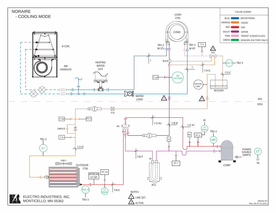
TXV
1/4-G
7/8-E
1/2-D
1/2-C
1/2-A11/2-A2
7/8-F
OUTDOORCOIL
7/8-B
1
1
COMP
F/D
LL
HL
BULB
T-3A
PT-1A
PT-1
PT-2T-4
PT-3
T-2A
RV
POWERSOURCE(AMPS)
HIT
HIPRESS
ACC
FAN 1
CT
SUC-C
SPORLAN5H T&P
IDUGAS TEMP
IDU
ODU
T-3
ORIFICE
LOPRESS
500 PSIGLIMIT
RECEIVER
NR203 P2Rev. 04 07-21-2011
NORAIRE- COOLING MODE
WATERLOAD
LOADCOIL
COND
TB3-3TB3-2
IN T7T8
TB2-2
J6
TB2-3
TB3-3
TB2-2
W-STc W-RT
AIRHANDLER
ELECTRO INDUSTRIES, INC.MONTICELLO, MN 55362
P
COLOR LEGEND
BLUE WATER PIPING
ORANGE LIQUID
RED GAS
VIOLET VAPOR
PINK “MIXED” (LIQUID & GAS)
GREEN SENSORS (FACTORY ONLY)
A-COIL
HEATINGWATER
OUT
NOTES:
1 LINE SET.
1 1
2 ACTIVE.
2
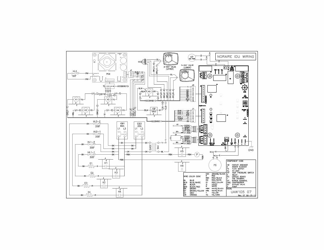
Page 1 of 2 XX017
Electro Industries, Inc. Residential
Limited Product Warranty Effective November 1, 2009
Electro Industries, Inc. warrants to the original owner, at the original installation site, for a period of two (2) years from date of original purchase, that the product and product parts manufactured by Electro Industries, Inc. are free from manufacturing defects in materials and workmanship, when used under normal conditions and when such product has not been modified or changed in any manner after leaving the plant of Electro Industries, Inc. If any product or product parts manufactured by Electro Industries, Inc. are found to have manufacturing defects in materials or workmanship, such will be repaired or replaced by Electro Industries, Inc. Electro Industries, Inc., shall have the opportunity to directly, or through its authorized representative, examine and inspect the alleged defective product or product parts. Electro Industries, Inc. may request that the materials be returned to Electro Industries, Inc. at owner’s expense for factory inspection. The determination as to whether product or product parts shall be repaired, or in the alternative, replaced, shall be made by Electro Industries, Inc. or its authorized representative. Electro Industries, Inc. will cover labor costs according to the Repair / Replacement Labor Allowance Schedule for a period of ninety (90) days from the date of original purchase, to the original owner, at the original installation site. The Repair / Replacement Labor Allowance is designed to reduce the cost of repairs. This Repair / Replacement Labor Allowance may not cover the entire labor fee charged by your dealer / contractor. TWENTY YEAR (20) LIMITED WARRANTY ON BOILER ELEMENTS AND VESSELS Electro Industries, Inc. warrants that the boiler elements and vessels of its products are free from defects in materials and workmanship through the twentieth year following date of original purchase. If any boiler elements or vessels are found to have a manufacturing defect in materials or workmanship, Electro Industries, Inc. will replace them. TWENTY YEAR (20) LIMITED WARRANTY ON SPIN FIN ELEMENTS Electro Industries, Inc. warrants that the spin fin elements of its products are free from defects in materials and workmanship through the twentieth year following date of original purchase. If any spin fin elements are found to have a manufacturing defect in materials or workmanship, Electro Industries, Inc. will replace them. FIVE YEAR (5) LIMITED WARRANTY ON OPEN WIRE ELEMENTS
Electro Industries, Inc. warrants that the open wire elements of its products are free from defects in materials and workmanship through the fifth year following date of original purchase. If any open wire elements are found to have a manufacturing defect in materials or workmanship, Electro Industries, Inc. will replace them.
Page 2 of 2 XX017
CONDITIONS AND LIMITATIONS:
1. This warranty is limited to residential, single family dwelling installations only. Any commercial or multi-unit dwelling installations fall under the Electro Industries Commercial Limited Product Warranty.
2. Electro Industries, Inc. shall not be liable for performance related issues resulting from improper installation, improper sizing, improper duct or distribution system, or any other installation deficiencies.
3. If at the time of a request for service the original owner cannot provide an original sales receipt or a warranty card registration then the warranty period for the product will have deemed to begin the date the product is shipped from the factory and NOT the date of original purchase.
4. The product must have been sold and installed by a licensed electrician, plumbing, or heating contractor. 5. The application and installation of the product must be in compliance with Electro Industries, Inc. specifications,
as stated in the installation and instruction manual, and all state, provincial and federal codes and statutes. If not, the warranty will be null and void.
6. The purchaser shall have maintained the product in accordance with the manual that accompanies the unit. Annually, a qualified and licensed contractor must inspect the product to assure it is in proper working condition.
7. All related heating components must be maintained in good operating condition. 8. All lines must be checked to confirm that all condensation drains properly from the unit. 9. Replacement of a product or product part under this limited warranty does not extend the warranty term or
period. 10. Replacement product parts are warranted to be free from defects in material and workmanship for ninety (90)
days from the date of installation. All exclusions, conditions, and limitations expressed in this warranty apply. 11. Before warranty claims will be honored, Electro Industries, Inc. shall have the opportunity to directly, or through
its authorized representative, examine and inspect the alleged defective product or product parts. Remedies under this warranty are limited to repairing or replacing alleged defective product or product parts. The decision whether to repair or, in the alternative, replace products or product parts shall be made by Electro Industries, Inc. or its authorized representative.
THIS WARRANTY DOES NOT COVER:
1. Costs for labor for diagnosis, removal or reinstallation of an alleged defective product or product part, transportation to Electro Industries, Inc., and any other materials necessary to perform the exchange, except as stated in this warranty. Replacement material will be invoiced to the distributor in the usual manner and will be subject to adjustment upon verification of defect.
2. Any product or product part that has been damaged as a result of being improperly serviced or operated, including, but not limited to, the following: operated during construction phase, with insufficient water or air flow; allowed to freeze; subjected to flood conditions; subjected to improper voltages or power supplies; operated with air flow or water conditions and/or fuels or additives which cause unusual deposits or corrosion in or on the product; chemical or galvanic erosion; improper maintenance or subject to any other abuse or negligence.
3. Any product or product part that has been damaged as a result of natural disasters, including, but not limited to, lightning, fire, earthquake, hurricanes, tornadoes or floods.
4. Any product or product part that has been damaged as a result of shipment or handling by the freight carrier. It is the receiver’s responsibility to claim and process freight damage with the carrier.
5. Any product or product part that has been defaced, abused or suffered unusual wear and tear as determined by Electro Industries, Inc. or its authorized representative.
6. Workmanship of any installer of the product or product part. This warranty does not assume any liability of any nature for unsatisfactory performance caused by improper installation.
7. Transportation charges for any replacement product, product part or component, service calls, normal maintenance; replacement of fuses, filters, refrigerant, etc.
THESE WARRANTIES DO NOT EXTEND TO ANYONE EXCEPT THE ORIGINAL PURCHASER AT RETAIL AND ONLY WHEN THE PRODUCT IS IN THE ORIGINAL INSTALLATION SITE. THE REMEDIES SET FORTH HEREIN ARE EXCLUSIVE.
ALL IMPLIED WARRANTIES, INCLUDING WARRANTIES OF MERCHANTABILITY AND FITNESS FOR A PARTICULAR PURPOSE, ARE HEREBY DISCLAIMED WITH RESPECT TO ALL PURCHASERS OR OWNERS. ELECTRO INDUSTRIES, INC. IS NOT BOUND BY PROMISES MADE BY OTHERS BEYOND THE TERMS OF THESE WARRANTIES. FAILURE TO RETURN THE WARRANTY CARD SHALL HAVE NO EFFECT ON THE DISCLAIMER OF THESE IMPLIED WARRANTIES.
ALL EXPRESS WARRANTIES SHALL BE LIMITED TO THE DURATION OF THIS EXPRESS LIMITED WARRANTIES SET FORTH HEREIN AND EXCLUDE ANY LIABILITY FOR CONSEQUENTIAL OR INCIDENTAL DAMAGES RESULTING FROM THE BREACH THEREOF. SOME STATES OR PROVINCES DO NOT ALLOW THE EXCLUSION OR LIMITATION OF INCIDENTAL OR CONSEQUENTIAL DAMAGES, SO THE ABOVE LIMITATIONS OR EXCLUSIONS MAY NOT APPLY. PRODUCTS OR PARTS OF OTHER MANUFACTURERS ATTACHED ARE SPECIFICALLY EXCLUDED FROM THE WARRANTY.
THIS WARRANTY GIVES YOU SPECIFIC LEGAL RIGHTS, AND YOU MAY HAVE OTHER RIGHTS WHICH VARY UNDER THE LAWS OF EACH STATE. IF ANY PROVISION OF THIS WARRANTY IS PROHIBITED OR INVALID UNDER APPLICABLE STATE OR PROVINCIAL LAW, THAT PROVISION SHALL BE INEFFECTIVE TO THE EXTENT OF THE PROHIBITION OR INVALIDITY WITHOUT INVALIDATING THE REMAINDER OF THE AFFECTED PROVISION OR THE OTHER PROVISIONS OF THIS WARRANTY.
XX036
XX036