
INDIA’S FIRST INDIGENOUSLY DEVELOPED HELIUM LIQUEFIER Proceedings/I... · INDIA’S FIRST...
4
INDIA’S FIRST INDIGENOUSLY DEVELOPED HELIUM LIQUEFIER P K Kush, R S Doohan, Prabhat K Gupta, R C Sharma, Rupul Ghosh, Manoj Kumar and P D Gupta Raja Ramanna Centre for Advanced Technology, Indore, INDIA Abstract We report the first indigenous development of helium liquefier at Cryo-engineering and Cryo-module Development Section at Raja Ramanna Centre for Advanced Technology, Indore. This system is based on reciprocating type expansion engine and uses cross counter flow type heat exchangers, based on high finned density copper tubes. The cyclic compressor is a four stage air cooled reciprocating type compressor. Its oil removal system is also designed and developed indigenously. Helium gas from commercial cylinders, as well as that recovered from user experiments, is used for liquefying, after passing it through a liquid nitrogen based gas purifier, made locally. First successful liquefaction in this system was achieved on August 14, 2010 at 4.35K, 1140 mbara, approx. 2.5 psig. This was for the first time in the country using a indigenously developed system. More than 150 liters of liquid helium was collected during its maiden trial itself, while operating for more than 25 hours continuously. Details of the liquefier system and the performance of different components are presented in this paper. INTRODUCTION Perhaps the easiest method to liquefy helium is to use a cascaded system in which helium gas is pre-cooled first using liquid nitrogen and then by liquid hydrogen and finally expanded through a Joule Thomson valve, such as in case of Linde-Hampson systems. Several such pre- cooled systems were developed by Mann et al. [1]. One of the milestones in cryogenic engineering was the design and development of a helium liquefier by Samuel C. Collins, in which both the pre-cooling stages were replaced by two expansion engines. Even today helium liquefaction systems are based straight on Collins cycle or its variants. System developed at RRCAT is also based on Collins cycle. The Collins cycle basically consists of two numbers of refrigeration producing devices called expanders, train of heat exchangers, covering a temperature range from 300K to 6K and a Joule Thomson valve. Helium gas is compressed in a cyclic compressor, also called main process compressor. Schematic of such a system is shown in figure 1. Helium liquefaction process in this system is explained as follows. High pressure gas passes through 1 st heat exchanger HX-1, see figure 1 below. During the
Transcript of INDIA’S FIRST INDIGENOUSLY DEVELOPED HELIUM LIQUEFIER Proceedings/I... · INDIA’S FIRST...

INDIA’S FIRST INDIGENOUSLY DEVELOPED HELIUM LIQUEFIER
P K Kush, R S Doohan, Prabhat K Gupta, R C Sharma, Rupul Ghosh, Manoj Kumar and P D Gupta
Raja Ramanna Centre for Advanced Technology, Indore, INDIA
Abstract
We report the first indigenous development of helium
liquefier at Cryo-engineering and Cryo-module
Development Section at Raja Ramanna Centre for
Advanced Technology, Indore. This system is based on
reciprocating type expansion engine and uses cross
counter flow type heat exchangers, based on high finned
density copper tubes. The cyclic compressor is a four
stage air cooled reciprocating type compressor. Its oil
removal system is also designed and developed
indigenously. Helium gas from commercial cylinders, as
well as that recovered from user experiments, is used for
liquefying, after passing it through a liquid nitrogen based
gas purifier, made locally. First successful liquefaction in
this system was achieved on August 14, 2010 at 4.35K,
1140 mbara, approx. 2.5 psig. This was for the first time
in the country using a indigenously developed system.
More than 150 liters of liquid helium was collected during
its maiden trial itself, while operating for more than 25
hours continuously. Details of the liquefier system and the
performance of different components are presented in this
paper.
INTRODUCTION
Perhaps the easiest method to liquefy helium is to use a
cascaded system in which helium gas is pre-cooled first
using liquid nitrogen and then by liquid hydrogen and
finally expanded through a Joule Thomson valve, such as
in case of Linde-Hampson systems. Several such pre-
cooled systems were developed by Mann et al. [1]. One of
the milestones in cryogenic engineering was the design
and development of a helium liquefier by Samuel C.
Collins, in which both the pre-cooling stages were
replaced by two expansion engines.
Even today helium liquefaction systems are based straight
on Collins cycle or its variants. System developed at
RRCAT is also based on Collins cycle. The Collins cycle
basically consists of two numbers of refrigeration
producing devices called expanders, train of heat
exchangers, covering a temperature range from 300K to
6K and a Joule Thomson valve. Helium gas is
compressed in a cyclic compressor, also called main
process compressor. Schematic of such a system is shown
in figure 1. Helium liquefaction process in this system is
explained as follows. High pressure gas passes through 1st
heat exchanger HX-1, see figure 1 below. During the

passage, it exchanges heat with outgoing low pressure
gas. On exit its temperature reduces to about 80 K. At this
stage it may be pre-cooled using liquid nitrogen. In a
system optimised for Liquid nitrogen (LN2) pre-cooling,
the liquid helium production rate can be doubled as
compared to without LN2 pre-cooling, while consuming
same electrical power. Then this high pressure gas passes
through 2nd
heat exchanger HX-2. Again it exchanges
heat with cold low pressure gas return stream and its
temperature reduces to about 50 K. Now a part, about
40%, of the total gas flow passes through first expansion
engine EE-1. On expansion the temperature of gas
reduces to about 40K. This gas after expansion enters the
low pressure gas stream, and returns to compressor
suction. While passing through 3rd
heat exchanger HX-3,
it cools the remaining 60% high pressure gas. After
cooling through 4th
heat exchanger HX-4 flow is again
split. About 40% of the total flow passes through the
second expansion engine EE-2. Here the temperature of
gas reduces to about 12K after expansion. This 12K gas
cools now remaining 20% gas while passing through 5th
heat exchanger HX-5. Now high pressure gas is passed
through the last heat exchanger HX-6, also called J-T heat
exchanger. This heat exchanger plays the most crucial
part in achieving the liquefaction rate of the system.
Finally, the high pressure gas expands through Joule
Thomson (J-T) valve. On expansion through J-T valve, a
fraction of the flow forms helium mist. This fraction
depends on the temperature and pressure of helium gas at
the inlet of J-T expansion (high pressure) and the final
expansion pressure. This mist settles as liquid in the
Dewar. The remaining vapours returns to the suction port
of the compressor while passing through heat exchangers.
On passing through different heat exchangers it cools the
incoming high pressure gas. All the components operating
at temperatures lower than ambient temperature are
housed in a stainless steel container called “cold box”.
High vacuum and cryogenic insulation, also called multi
layer insulation (MLI) is used to insulate these
components thermally from ambient temperature.
DEVELOPMENT OF HELIUM
LIQUEFIER
Reciprocating Type Cryogenic Expanders
Expanders work on the basic principle of extracting work
from the high pressure gas. As the gas is doing external
work, it gets cooled. The external work method always
produces cooling in comparison to “internal work
method”, called Joule Thomson expansion. For a gas to
cool through a Joule Thomson expansion, it is essential
that its temperature should be below a certain
temperature, called inversion temperature. For helium gas
the inversion temperature is at about 45K. Refrigeration
required to cool the gas is produced using two expanders.
Expanders can be of two types; turbine type and
reciprocating type. Reciprocating type expanders have
following distinct advantages over the turbine types: high
expansion ratio, low gas flow rate, constant efficiency
over wide range of operating conditions, less sensitive to
impurities and power fluctuation problems, control of
speed/ flow rate is easier. In addition, fabrication of
reciprocating type expansion engines is less complicated
as compared to turbine type expanders. Although, the
turbine type expanders can give better thermodynamic
efficiency as compared to reciprocating type. They are
suitable for large constant cryogenic load operating over a
prolonged period.
Table-1: Parameters for 1st Expansion Engine
Diameter: 75 mm, Stroke: 50 mm, Engine speed: 120 rpm
Inlet cam opening angle: 50 deg Inlet gas pressure: 17.21 bara,
Inlet Temp., K Expander Eff., % Mass flow rate, g/s
300 77 0.22
80 68 0.80
50 64 1.26
Table-2: Parameters for 2nd Expansion Engine
Diameter: 50 mm, Stroke: 50 mm, Engine speed: 120 rpm
Inlet cam opening angle: 45 deg, Inlet gas pressure: 17.21 bara,
Inlet Temp., K Expander Eff., % Mass flow rate, g/s
300 86 0.08
80 81 0.29
25 75 0.92
At RRCAT we have developed reciprocating type
cryogenic expansion engines to operate at 50K and 20K
[2]. Photograph of the system is shown in Figure 2.
Technical parameters of expansion engines developed by
RRCAT are given in table (1) and (2). Expander
efficiencies are calculated from experimental data. Both
the expansion engines were designed at RRCAT and
fabricated by local fabricators. These engines consist of
extended length FRP pistons. Low thermal conductivity
Figure 2: Photograph showing expansion engine
developed at RRCAT. 1. Cryogenic Expander, 2. Work
extraction mechanism, 3. 1st heat exchanger, 4. Flywheel
of FRP and long length results in reduction of heat in-
leaks through conduction form room temperature to the
expansion space. FRP procured from local market is used.
Due to the extended length, the expansion process takes
place deep inside the cold box, whereas other components
of expansion engines such as fly wheel, inlet and exhaust
valve actuators, work extraction mechanism, etc operate
at room temperature. The gaps between the piston and
expander liner, also called “void volume”, plays an
important role in achieving the required expansion
efficiency. An alternator, used in automobiles, is suitably
modified to work as “work extraction device”.
Cryogenic Heat Exchangers
Another crucial part of a helium liquefier is its heat
exchangers. In early days people have developed and used
different types of heat exchangers. Description of those
types is beyond the scope of this article. Now a day’s
state of the art is counter flow aluminium plate fin heat
exchangers. These can offer maximum heat transfer area
in unit volume, typically 1300 to 1400 m2/ m
3. They use
high fin density aluminium fins (more than 1.2 fins per
mm), sandwiched between claded aluminium sheets.
Sides are sealed with side bars and this block is brazed
using vacuum brazing techniques. Finally headers are
joined to provide separate passage for the hot and cold
gas streams. Due to their cost and complexity, these heat
exchangers are more suited for large flow rate machines.
Other option, especially for low gas flow rates is to go for
heat exchangers made of high fined density copper tubes
in a cross counter flow configuration. From fabrication
and cost point of view these heat exchangers are the
choice at low to moderate flow rates. At RRCAT we have
designed and developed heat exchangers using integral
finned tubes made by an Indian manufacturer [3, 4]. We
have used six numbers of cross counter flow type heat
exchangers operating between different temperature
ranges (300K to 6K).
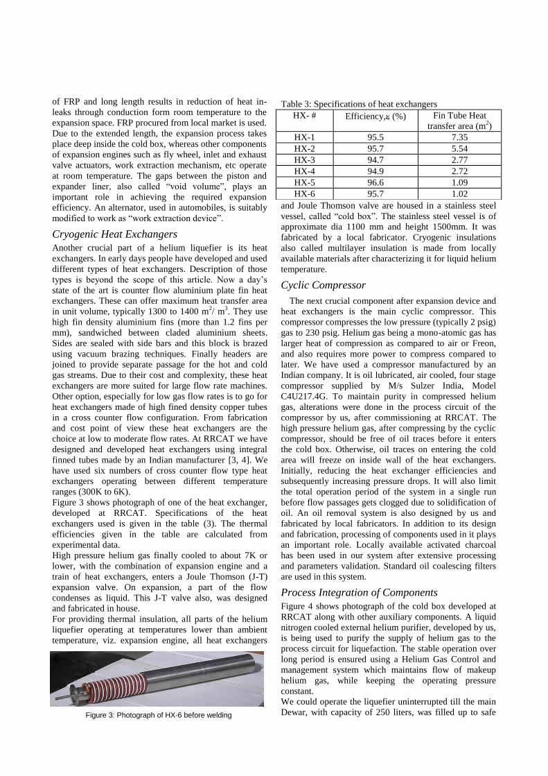
Figure 3 shows photograph of one of the heat exchanger,
developed at RRCAT. Specifications of the heat
exchangers used is given in the table (3). The thermal
efficiencies given in the table are calculated from
experimental data.
High pressure helium gas finally cooled to about 7K or
lower, with the combination of expansion engine and a
train of heat exchangers, enters a Joule Thomson (J-T)
expansion valve. On expansion, a part of the flow
condenses as liquid. This J-T valve also, was designed
and fabricated in house.
For providing thermal insulation, all parts of the helium
liquefier operating at temperatures lower than ambient
temperature, viz. expansion engine, all heat exchangers
and Joule Thomson valve are housed in a stainless steel
vessel, called “cold box”. The stainless steel vessel is of
approximate dia 1100 mm and height 1500mm. It was
fabricated by a local fabricator. Cryogenic insulations
also called multilayer insulation is made from locally
available materials after characterizing it for liquid helium
temperature.
Cyclic Compressor
The next crucial component after expansion device and
heat exchangers is the main cyclic compressor. This
compressor compresses the low pressure (typically 2 psig)
gas to 230 psig. Helium gas being a mono-atomic gas has
larger heat of compression as compared to air or Freon,
and also requires more power to compress compared to
later. We have used a compressor manufactured by an
Indian company. It is oil lubricated, air cooled, four stage
compressor supplied by M/s Sulzer India, Model
C4U217.4G. To maintain purity in compressed helium
gas, alterations were done in the process circuit of the
compressor by us, after commissioning at RRCAT. The
high pressure helium gas, after compressing by the cyclic
compressor, should be free of oil traces before it enters
the cold box. Otherwise, oil traces on entering the cold
area will freeze on inside wall of the heat exchangers.
Initially, reducing the heat exchanger efficiencies and
subsequently increasing pressure drops. It will also limit
the total operation period of the system in a single run
before flow passages gets clogged due to solidification of
oil. An oil removal system is also designed by us and
fabricated by local fabricators. In addition to its design
and fabrication, processing of components used in it plays
an important role. Locally available activated charcoal
has been used in our system after extensive processing
and parameters validation. Standard oil coalescing filters
are used in this system.
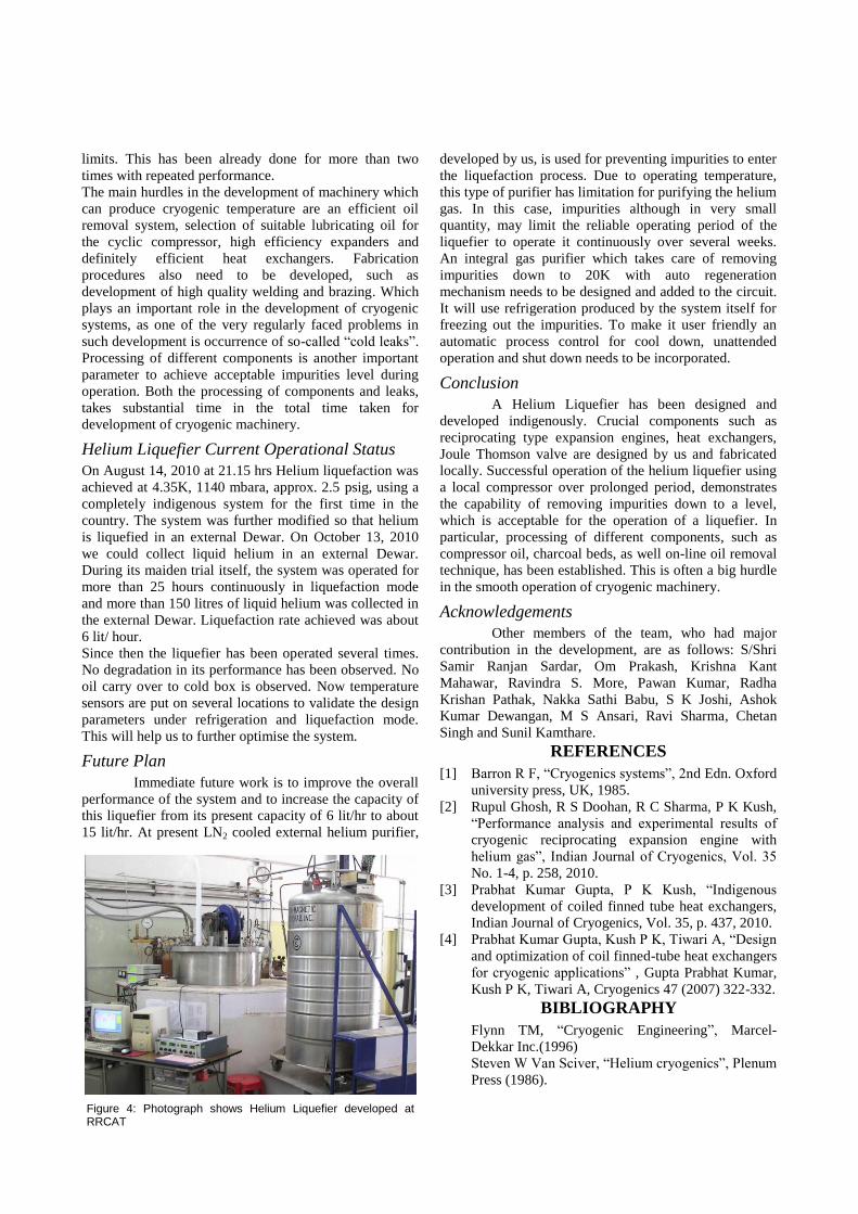
Process Integration of Components
Figure 4 shows photograph of the cold box developed at
RRCAT along with other auxiliary components. A liquid
nitrogen cooled external helium purifier, developed by us,
is being used to purify the supply of helium gas to the
process circuit for liquefaction. The stable operation over
long period is ensured using a Helium Gas Control and
management system which maintains flow of makeup
helium gas, while keeping the operating pressure
constant.
We could operate the liquefier uninterrupted till the main
Dewar, with capacity of 250 liters, was filled up to safe
Table 3: Specifications of heat exchangers
HX- # Efficiency, (%) Fin Tube Heat
transfer area (m2)
HX-1 95.5 7.35
HX-2 95.7 5.54
HX-3 94.7 2.77
HX-4 94.9 2.72
HX-5 96.6 1.09
HX-6 95.7 1.02
Figure 3: Photograph of HX-6 before welding
limits. This has been already done for more than two
times with repeated performance.
The main hurdles in the development of machinery which
can produce cryogenic temperature are an efficient oil
removal system, selection of suitable lubricating oil for
the cyclic compressor, high efficiency expanders and
definitely efficient heat exchangers. Fabrication
procedures also need to be developed, such as
development of high quality welding and brazing. Which
plays an important role in the development of cryogenic
systems, as one of the very regularly faced problems in
such development is occurrence of so-called “cold leaks”.
Processing of different components is another important
parameter to achieve acceptable impurities level during
operation. Both the processing of components and leaks,
takes substantial time in the total time taken for
development of cryogenic machinery.
Helium Liquefier Current Operational Status
On August 14, 2010 at 21.15 hrs Helium liquefaction was
achieved at 4.35K, 1140 mbara, approx. 2.5 psig, using a
completely indigenous system for the first time in the
country. The system was further modified so that helium
is liquefied in an external Dewar. On October 13, 2010
we could collect liquid helium in an external Dewar.
During its maiden trial itself, the system was operated for
more than 25 hours continuously in liquefaction mode
and more than 150 litres of liquid helium was collected in
the external Dewar. Liquefaction rate achieved was about
6 lit/ hour.
Since then the liquefier has been operated several times.
No degradation in its performance has been observed. No
oil carry over to cold box is observed. Now temperature
sensors are put on several locations to validate the design
parameters under refrigeration and liquefaction mode.
This will help us to further optimise the system.
Future Plan
Immediate future work is to improve the overall
performance of the system and to increase the capacity of
this liquefier from its present capacity of 6 lit/hr to about
15 lit/hr. At present LN2 cooled external helium purifier,
developed by us, is used for preventing impurities to enter
the liquefaction process. Due to operating temperature,
this type of purifier has limitation for purifying the helium
gas. In this case, impurities although in very small
quantity, may limit the reliable operating period of the
liquefier to operate it continuously over several weeks.
An integral gas purifier which takes care of removing
impurities down to 20K with auto regeneration
mechanism needs to be designed and added to the circuit.
It will use refrigeration produced by the system itself for
freezing out the impurities. To make it user friendly an
automatic process control for cool down, unattended
operation and shut down needs to be incorporated.
Conclusion
A Helium Liquefier has been designed and
developed indigenously. Crucial components such as
reciprocating type expansion engines, heat exchangers,
Joule Thomson valve are designed by us and fabricated
locally. Successful operation of the helium liquefier using
a local compressor over prolonged period, demonstrates
the capability of removing impurities down to a level,
which is acceptable for the operation of a liquefier. In
particular, processing of different components, such as
compressor oil, charcoal beds, as well on-line oil removal
technique, has been established. This is often a big hurdle
in the smooth operation of cryogenic machinery.
Acknowledgements
Other members of the team, who had major
contribution in the development, are as follows: S/Shri
Samir Ranjan Sardar, Om Prakash, Krishna Kant
Mahawar, Ravindra S. More, Pawan Kumar, Radha
Krishan Pathak, Nakka Sathi Babu, S K Joshi, Ashok
Kumar Dewangan, M S Ansari, Ravi Sharma, Chetan
Singh and Sunil Kamthare.
REFERENCES
[1] Barron R F, “Cryogenics systems”, 2nd Edn. Oxford
university press, UK, 1985.
[2] Rupul Ghosh, R S Doohan, R C Sharma, P K Kush,
“Performance analysis and experimental results of
cryogenic reciprocating expansion engine with
helium gas”, Indian Journal of Cryogenics, Vol. 35
No. 1-4, p. 258, 2010.
[3] Prabhat Kumar Gupta, P K Kush, “Indigenous
development of coiled finned tube heat exchangers,
Indian Journal of Cryogenics, Vol. 35, p. 437, 2010.
[4] Prabhat Kumar Gupta, Kush P K, Tiwari A, “Design
and optimization of coil finned-tube heat exchangers
for cryogenic applications” , Gupta Prabhat Kumar,
Kush P K, Tiwari A, Cryogenics 47 (2007) 322-332.
BIBLIOGRAPHY
Flynn TM, “Cryogenic Engineering”, Marcel-
Dekkar Inc.(1996)
Steven W Van Sciver, “Helium cryogenics”, Plenum
Press (1986).
Figure 4: Photograph shows Helium Liquefier developed at RRCAT


