Studies of hydrogen liquefier efficiency and the recovery ...
72
FILE COPY NBSIR 77-862 IX) NOT REMO\^ STUDIES OF HYDROGEN LIQUEFIER EFFICIENCY AND THE RECOVERY OF THE LIQUEFACTION ENERGY R.O. Voth W.R. Parrish Cryogenics Division Institute for Basic Standards National Bureau of Standards Boulder, Colorado 80302 August 1977
Transcript of Studies of hydrogen liquefier efficiency and the recovery ...

FILE COPY
NBSIR 77-862 IX) NOT REMO\^
STUDIES OF HYDROGEN LIQUEFIER EFFICIENCY AND THE
RECOVERY OF THE LIQUEFACTION ENERGY
R.O. Voth
W.R. Parrish
Cryogenics Division
Institute for Basic Standards
National Bureau of Standards
Boulder, Colorado 80302
August 1977


IMBSIR 77-8 62
STUDIES OF HYDROGEN LIQUEFIER EFFICIENCY AND THE
RECOVERY OF THE LIQUEFACTION ENERGY
R.O. Voth
W.R. Parrish
Cryogenics Division
Institute for Basic Standards
National Bureau of Standards
Boulder, Colorado 80302
August 1977
U.S. DEPARTMENT OF COMMERCE, Juanita M. Kreps, Secretary
Sidney Harman, Under Secretary
Jordan J. Baruch, Assistant Secretary for Science and Technology
NATIONAL BUREAU OF STANDARDS. Ernest Ambler, Acting Director


CONTENTSPage
CHAPTER 1. HYDROGEN LIQUEFIER EFFICIENCY 1R. 0. Voth
1. SUMMARY 1
1.1. Introduction 1
1.2. Derivation of the Defined Cycle 2
1.2.1. Losses due to expander and compressorinefficiency 6
1.2.2. Losses due to heat exchanger temperaturedifference 8
1.2.3. Losses due to pressure drop 111.2.4. Multipressure liquefaction cycles 11
1.3. The Real Hydrogen Liquefier 111.3.1. Efficiency and losses of real liquefier
components 151.3.1.1. Compressor 151.3.1.2. Expanders 161.3.1.3. Joule-Thomson expansion valve ... 171.3.1.4. Expansion ejector valve 171.3.1.5. Heat exchangers 19
1.3.2. Real hydrogen liquefier cycle 191.3.2.1. The design of a practical
hydrogen liquefier 321.4. Comparison Between Defined Cycle and Real Gas
Cycle 351.5. Conclusions 351.6. Nomenclature 391.7. References 411.8. APPENDIX - Hydride Compressors 4 2
1.8.1. Introduction 421.8.2. Properties of metal hydrides 421.8.3. Hydride compressor system 42
CHAPTER 2. RECOVERY OF HYDROGEN LIQUEFACTION ENERGY 4 5
W. R. Parrish2. SUMMARY 4 5
2.1. Introduction 4 5
2.2. Electrical Utility Applications 462.2.1. Liquefaction energy recovery factor 462.2.2. Liquefaction energy recovery systems .... 47
2.3. Recovery of Rare Gases 512.3.1. Helium recovery process 522.3.2. Work limitations 522.3.3. Refrigeration limitations 53
2.4. Conclusions 532.4.1. Utility application 532.4.2. Rare gas recovery 53
2.5. References 54
2.6. APPENDIX - Air Plant Design 552.6.1. Design using an atmospheric column 552.6.2. Subatmospheric column 57
iii


ABSTRACT
Liquid hydrogen is a potential synthetic fuel. It is non-fossil, its production and storage technology is well developed,and it is inherently nonpolluting . However, the economics ofliquefying hydrogen are costly both in the energy required toproduce the liquid and in the capital costs of the liquefier.These costs could be reduced by increasing the liquefier effi-ciency and/or by recovering a portion of the liquefaction energyat the use site. This paper provides the maximum hydrogen liq-uefier efficiency based on the efficiency of available compo-nents and the fraction of original liquefaction energy that canbe recovered at the use site. Since the inefficient compressorsand expanders are the major cause of liquefier inefficiency, noincrease in liquefier efficiency above the current 30 to 35percent is probable without a corresponding increase in compres-sor and expander efficiency --a difficult task since both thecompressors and expanders have a long and stable history ofdevelopment. However, roughly one-third to one-half of theactual energy required to liquefy hydrogen can be recovered atthe use site and this represents a cost credit for liquid hydro-gen.
Key words: Component efficiency; cryogenics; efficiency; energyrecovery; hydrogen; liquefier.
iv


CHAPTER 1
HYDROGEN LIQUEFIER EFFICIENCY
R. 0. Voth
1. SUMMARY
The efficiency of current hydrogen liquefiers lies in the range of 30 to35 percent of Carnot. Since this efficiency appears low when it is comparedto other thermodynamic cycles, this study was undertaken to determine themaximum possible efficiency for large capacity mechanical liquefiers usingstate-of-the-art compressors, expanders, and heat exchangers. Two approacheswere used to determine the maximum efficiency. The first approach employs adefined liquefaction cycle that uses an ideal gas working fluid. Althoughthe working fluid is ideal, the real effects on liquefier efficiency of heatexchanger temperature difference, system pressure drop, and component effi-ciency can be determined. The second approach uses hydrogen properties inpractical cycles to determine maximum liquefier efficiency. With a real gasworking fluid the final expansion device could be a Joule Thomson valve, anexpansion ejector or a wet expander (the exhaust of the expander containsliquid) instead of the theoretical isothermal expander of the defined cycle.
The maximum liquefier efficiency found from the two approaches agreedclosely and they were in the range of 30 to 3 5 percent. Because the com-pressors and expanders were the major sources of inefficiency, no increasein liquefier efficiency is probable without a corresponding increase in thecompressor or expander efficiency -- a difficult task since both the com-pressors and expanders have a long and stable history of development. Con-sequently, higher liquefier efficiencies are not probable in the near future.
Because of the large dependence of the liquefier efficiency on compressorefficiency, a metal hydride compressor was investigated. The heat required bythe hydride compressor was obtained from the waste heat of a parallel mechan-ical compressor. However, because of the low quality of this heat, the hydridecompressor did not contribute significantly to an increase in the overallefficiency of the compressor system.
1.1. Introduction
The cost of producing liquid from gaseous hydrogen is an economic barrierto the early adoption of liquid hydrogen as an "energy carrier". Decreasingthe liquefaction costs is partially dependent on increasing the efficiency of
the liquefaction process above the current 30 to 35 percent [1] . This studyinvestigates the efficiency of hydrogen liquefiers in the following manner:
1) By using a defined cycle with a perfect gas working fluid, themaximum efficiency of the liquefier as a function of the efficiencyof the liquefier components is established. The defined cycleefficiency — the cycle is reversible for reversible components —includes the effects of component inefficiency, system pressure drop,and heat exchanger temperature difference.
2) The efficiencies of practical cycles with a real-gas (hydrogen)
working fluid are determined and compared to the defined cycleefficiencies. The practical liquefier is designed for maximumefficiency using a Joule Thomson expansion valve, an expansion ejector,or a wet expander as the final expansion device. The comparableefficiencies found by the defined cycle and the practical liquefier,
shows that the penalty in efficiency associated with the use of a
real gas can be made small with appropriate cycle selection.

As a result of these calculations, the inefficiency of the compressors and ex-panders are shown to have the most influence on the overall liquefier effi-ciency.
An unsuccessful attempt to increase the efficiency of the compressor bythe use of a metal hydride is shovm in Appendix A. Without an increase incompressor or expander efficiency, the current hydrogen liquefier efficienciesof 30 to 35 percent of Carnot will not be increased significantly in thefuture
.
1.2. Derivation of the Defined Cycle
The analysis of a hydrogen liquefaction cycle is a complex thermodynamicand economic problem. The thermodynamic complexity results from the non-ideal properties of hydrogen. For example, simple first law analysis does not\incover negative heat exchanger temperature differences dictated by the vari-able specific heats in the real gas when invalid boundary conditions are chosenTherefore, it is necessary to perform a more complex numerical analysis ofthe system heat exchangers. Variable properties also require optimization ofpressure ratios and temperature inlets for the expanders used in the system.
The analysis must also include economics. For example, a heat exchangerdesigned for small temperature differences will increase the overall cycleefficiency but require an increased capital expenditure. The usual approachto cycle studies is to make a parametric study of the liquefaction cycleusing a computer and then to choose one of the calculated cycles that is com-patible with available components. Although this approach gives exact re-sults, one is never quite sure that a different (and unconsidered) cyclemight not yield a superior efficiency.
By using a simple defined cycle which is reversible for reversible com-ponents, we are able to easily evaluate the effect of various system compo-nents, and to make a reasonably accurate estimate of the maximum possiblecycle efficiency with components of given efficiencies.
Liquefier efficiency is based on the equation:
•' ' _ Ideal power requirements ,^ 2 ^^cy Actual net power requirements
The net power required by the cycle is the required compressor power less therecoverable power from the expanders. The cycle efficiency should be 100percent when the components in the cycle are ideal and the effect of com-ponent losses in the cycle on cycle efficiency should be realistic.
By extending the earier work of Collins [2] for an ideal liquefactioncycle, the defined cycle shown schematically in figure 1.1 is derived. Thecycle uses a refrigeration loop to precool and condense a separate productstream. The refrigeration loop bypass turbines are situated so the inlettemperature of each expander is higher than the discharge temperature of thepreceding expander by the temperature difference of the heat exchanger. Theheat exchanger temperature difference is proportional to the absolute temper-ature as defined by a constant C = AT/T. The final expander in the refriger-ation loop is a theoretical isothermal expander used to condense the productstream. Both the refrigerant and the product streams are perfect gases withconstant specific heats. The product stream condenses at T^ with a latentheat 28.988 K times the specific heat (i.e., the same ratio as for hydrogen).Changing the latent heat ratio and the value of T^ would make the defined
cycle applicable to other fluids. The high temperature (heat rejection) endof the cycle (T„ figure 1.1) is taken as 300 K in the calculations, while the
ncold end temperature (T ) was taken as 20.268 K, the normal boiling pointof liquid parahydrogen
.
2

dIsothermall
Compressorh p^Q^ . ^
Product (i)
Figure 1.1. Schematic of the defined cycle.
3

The arrangement of the expanders in the precooling portion of the cycle(figure 1.1)/ is the most efficient arrangement because the refrigerationrequired by the product stream is exactly matched at each temperature by therefrigeration produced by the expanders. For reversible expanders and heatexchangers, this arrangement is reversible. For finite size heat exchangers,balanced flow maintains a constant heat exchanger temperature difference,and the flow through each expander is the same as the product stream flow,03. In order to maintain AT T in the heat exchanger (which minimizes theheat exchanger losses [3]), a slight imbalance in the flow is required, re-sulting in a slightly greater expander flow.
Returning to the definition of cycle efficiency (equation 1.2.1), thecycle efficiency can be written as
the overall cycle efficiency based on W^j^r
ideal liquefier power requirements,
actual total compressor power, and
the recoverable expander power.
The expander output can be recovered by using it to drive either a boostercompressor stage or an electrical generator to provide part of the power re-quired by the main compressor. In either case, the power required by theliquefier is reduced by part of the expander output. In the first case therequired compressor power is reduced by an amount equal to the expander powerassuming an equal efficiency for both compressors. In the second case therecoverable expander power is less than the expander output due to theinefficiency of gear trains and the electrical generator. In the calculationspresented here the total compressor power requirements were reduced by thetotal calculated expander power.
where
ncy
W .
ci
Wca
The ideal work of liquefaction is determined from the availability func-tion of the product.
where^ = ^1 - ^o - ^o (^1 - =0^
y = availability associated with the minimum work of formation,also the maximum work recoverable from a fluid at the definedstate,
T = absolute temperature,h = specific enthalpy,s = specific entropy and,
subscripts
1 = defined state — liquid hydrogen at 1 atmosphere,0 = ambient conditions -- 1 atmosphere pressure, 300 K temperature.
For a perfect gas system the ideal liquefaction power can be defined as thesum of: 1) the ideal power required to precool the product stream (W^^) , and
2) the ideal power required to condense the product (^2''' Precooling the pro-
duct stream occurs over a variable temperature, and the ideal work for thisprocess is given by Jacobs [4] as.
4

T - T.
^1 = -^T (1.2.4)Im
where
T = ambient temperature also equal to T„ for the liquefier,O ri
"^im = - ^c)/l^ (V^C^'= lowest refrigeration temperature,
Q = heat load equal to the product stream flow rate ((L) timesCp(T^ - , and
C = constant pressure specific heat.P
By replacing Q, the ideal work for the variable temperature process be-comes ,
T - T,W = -Afi ^(LC (T -T). (1.2.5)1 p H C
The ideal power required to condense the fluid at a constant temperatureis
T ,- T
W = Q {-^ ^) , (1.2.6)C
where
Q = A X (i), and
A = Latent heat.
Thus, the total ideal power required is,
T - T T - TW^. = Ar^ — (I) C (T - T ) + (L (A) (-^ ^) (1.2.7)ci T^^ p H C
or since A = 28.988 x C^,
T - T T — TW^. = — (I) C„(T„ - T ) + 28.988 C (L ^) . (1.2.8)ci
.T^^ p H C p
Since the minimum compressor power is a result of a reversible isothermalprocess, compressor efficiencies used in the calculations are based on theideal isothermal work of compression. For a perfect gas the isothermal com-pressor power is given by,
m RT iln PrW. = ^ (1.2.9)
where
= isothermal compression power,
m = mass flow through the compressor!
R = gas constant.
5

T„ = compression temperature (T = T )
,
H ri U
Pr = pressure ratio (high pressure/low pressure) , and
' - isothermal efficiency of the compressor.
The total flow through the compressor is the sum of the flows through the ex-panders, and the total expander flow is a function of losses in the cycle.These losses are a result of the inefficiency of the expanders, of heat ex-changer temperature differences and of system pressure drop. Each of theseloss effects will be covered separately.
1.2.1. Losses due to expander and compressor inefficiency
In this section only the losses from inefficient expanders and compressorswill be considered. The heat exchangers have zero temperature differencesand there is no system pressure drop.
The losses incurred by inefficient precooling expanders are a result ofa less than ideal temperature drop across the expanders. This decreased tem-perature drop increases the number of expanders required in the precoolingportion of the liquefier thereby increasing the compressor flow rate. Flowthrough the isothermal expander also increases with decreasing efficiency.With zero temperature difference in the heat exchanger, the flow through eachprecooling expander is equal to the product stream flow. Thus, the compressorflow due to the precooling expanders becomes
ra = N X 0) (1.2.10)pre exp ^'
where
m^^^ = total mass flow rate through the precooling expanders, and
^exp ~ number of precooling expanders.
The temperature drop across an expander operating with a perfect gas is
^in - Tout = Ve '^in "^^''^ (I-^'ID
where
= the expander inlet temperature,
T^^^ = the expander outlet temperature,
rip^g = isentropic efficiency of the precooling expanders,
Pr = pressure ratio across the expander,
a = (k - l)/k, and
k = ratio of specific heats (1.404 for hydrogen at ambient tempera-ture and zero pressure)
.
From figure 1.1, expressions for T^, T^, T , can be written based on theexpander efficiencies as follows ^
^2 (1 -npre
+ nprePr"") (1.2.12)
= T2 (1 - npre+ npre
Pr"") (1.2.13)
1
n+1= T
n (1 - npre+ npre
Pr"^). (1.2.14)

Assioming the same efficiency for all the precooling expanders and substitut-ing to maintain T„ in the equation yields,
nN
Solving for the number of expanders (N^^^) results in
In (^)N =
. (1.2.16)In (1 - n + n Pr~^)
pre pre
If the expanders are reversible, the equation reduces to
In (^)
^exp = ^ ' (1.2.17)In (Pr ^)
The recoverable power from each precooling expander becomes,
= ^ C (T.^ - T^^^), (1.2.18)pre
or summing from T„ down to T_, the total recoverable power becomesn C
Wj^ = ^ C {T^ - T^). (1.2.19)pre ^
The mass flow through the isothermal expander is related to the expanderefficiency and the flow and latent heat of the product stream as,
28.988 (Cp) (o))
"'iso " ~. T^R In Pr ' (1.2.20)ISO C
where28.988 Cp = latent heat of the product stream, J/mol,
n- = isothermal efficiency of the expander,ISO
and R = gas constant.
The recoverable power from the isothermal expander is equal to
W„ = 28. 988 (C„) ((L) . (1.2. 21)t\ • pISO
An equation for the overall cycle efficiency can now be written by sub-stituting into the general cycle efficiency expression, equation (1.2.2).
=:
^ (1.2.22)(m + m. ) R T„ Im Pr^re ^2 H
, , „^ ,
c pre ISO
7

minimum ideal-cycle power, equation (1.2.8) '
total mass flow through the precooling expanders, equations(1.2.10) and 1.2.16)
mass flow through the isothermal expander, equation (1.2.20)
recoverable work from the precooling expanders, equation(1.2.19)
recoverable work from the isothermal expander, equation(1.2.21)
.
The specific heat (C^) cancels in equation 1.2.22 when the results of the
previous equations are substituted. This leaves the condensing temperature(T^) , the ratio of latent heat to specific heat, and the ratio of specifc
heats (k) as the only parameters relating the equation to a hydrogen lique-fier. Although the specific heat ratio, k, varies over a broad range as thetemperature of hydrogen is reduced, it was found that this variation affectedthe optimum pressure ratio for the cycle but had little effect on the maxi-mum cycle efficiency shown in the results. The ratio of latent heat tospecific heat (28.988 K) was determined for the case of equilibrium conversionfrom normal to parahydrogen as the temperature of the product stream is re-duced. The effect of conversion at temperatures lower than equilibrium canbe determined by varying the latent heat to specific heat ratio.
Cycle efficiencies as a function of expander and compressor efficienciesare shown on figure 1.2. In this figure the precooling expanders and theisothermal expander were assumed to have the same numerical efficiency. Theplotted results are for a liquefier with six precooling expanders.
The results show that without considering any losses from heat exchangertemperature differences or pressure drop, the maximum cycle efficiency obtain-able with 80 percent of adiabatic precooling expanders, an 80 percent isothermalexpander, and a 60 percent isothermal compressor is approximately 40 percentof Carnot.
1.2.2. Losses due to heat exchanger temperature difference
Calculation of the effect of heat exchanger temperature difference onoverall liquefier efficiency greatly complicates the simple equation used inthe previous section. This complication results because losses in the colderportion of the cycle compound the losses due to heat exchanger temperaturedifferences in the warmer portion of the cycle. The cycle efficiency calcu-lation must therefore become more specific about flow rates in each heatexchanger and through each expander. In the previous cycle efficiency calcu-lation, the number of expanders could be non-integer without affecting thevalidity of the results. However, in considering the heat exchanger tempera-ture differences losses, the number of expanders must be integer.
When heat exchanger temperature differences are considered, the numberof precooling expanders required in the cycle is increased because of theoverlaps between the discharge temperature of a previous expander and theinlet temperature of the following expander. Also, the flow through eachexpander must be higher than the product stream flow rate because the tempera-ture difference in each heat exchanger decreases with absolute temperature.
The procedure followed was to select a number of precooling expanders,solve for the required pressure ratio and determine the flow through the iso-thermal expander. Using this flow as the inlet and discharge flow to thebottom or coldest portion of the n*^^ heat exchanger (figure 1.1), the requiredflow to the top or warm end of the same heat exchanger was determined from an
where
Wci
m .
pre
m
.
ISO
pre
and =
iso
8

LUQn l I I I I
\ \ \ \ \ \ I I
40 50 60 70 80 90 100
EXPANDER EFFICIENCY, %
Isothermal Condensinq Expander has the same Numerical
Efficiency as the Adiabatic Precooling Expanders
Figure 1.2. Defined cycle efficiency without pressure drop and heat exchangertemperature difference losses.
9

energy balance around the heat exchanger. The product flow stream maintainsits flow of 0) throughout the procedure. The flow at the top of the nth heatexchanger now becomes the inlet and discharge flow for the cold end of the(n - 1) heat exchanger. The summing procedure continues to the compressorend of the cycle when the total compressor flow is determined.
The pressure ratio determination is made by deriving an equation similarto equation (1.2.15) except that C (where C = AT/T, used to define heat ex-change temperature difference) is included in the derivation. Equation(1.2.15) now becomes
(1.2.23)
pre
L[(l - C)(T^/T^) + Hp^^ - 1]
(1.2.24)
By selecting the number of expanders, a required pressure ratio can be calcu-lated.
Performing an energy balance around each heat exchanger, the followingequations were derived and used to calculate the overall cycle efficiency.
1. m = m . + mISO pre
where
n=lZ
n=Nm
exp
n=lI
n=N
(jj + mn+1
1 - C(1.2.25)
exp
m
m.
exp+1
the total mass flow through the expanders
mass flow through the isothermal expander orm. from equation (1.2.20).ISO ^ V /
n=l2- W^ = "r ^ = Wr. £ ^-.l^Cpf^n - ^n^l (1-^)1 (^•2-26)
pre ISO iso n=N
where
exp
"Nexp+1
total recoverable expander power,
T^
ISOrecoverable power from the isothermal expanderequation (1.2.21).
pre
and
recoverable power from the precooling expanders,
T = T ^,/[l - n + n Pr~°')/(1 -c)]n n+1 pre pre
10

w .
3. n = ^. (1.2.27)
^ m RT„ In Pr« W
The results of the calculated cycle efficiency including losses due toheat exchanger temperature difference will be presented in the next section.
1.2.3. Losses due to pressure drop
The pressure drop losses were included in the cycle efficiency calcu-lation in a rather inexact method. Since it was difficult to calculate thelosses when the pressure drop was distributed throughout the system, cycleefficiencies were calculated with the entire pressure drop occurring at twolocations. The minimum losses due to system pressure drop were calculatedby taking the entire pressure drop immediately before and after the isothermalexpander. The maximum loss was determined by taking the entire pressure dropimmediately before and after the main compressor. In the calculations thereduced pressure ratio for either the isothermal expander or the entire cyclewas found by
:
P^r = ''^ a I AP/p!•
Figures 1.3 and 1.4 show the final results of the cycle efficiency analy-sis. All losses are included in the plots with the double line denoting themaximum and minimum pressure drop effect. The cycle efficiency varied withthe number of expanders and if the maximum efficiency occurred with less thansix expanders that point was plotted, otherwise the cycle efficiency for sixprecooling expanders was plotted.
1.2.4. Multipressure liquefaction cycles
Losses in the cold end of the liquefaction cycle increase the flow in thewarm end of the cycle. This increased warm end flow results in increased warmend losses. To minimize these losses, a three pressure cycle (employed in moststate-of-the-art hydrogen liquefiers) can be simulated with the defined cycleby increasing the pressure ratio across the isothermal expander while main-taining the pressure ratio across the precooling expanders. Although thethree pressure cycle requires an additional compressor and more complex heatexchangers, an increase in the cycle efficiency of one to two percentage pointscan be attained as shown by figure 1.5. The results shown on figure 1.5 arefor a fixed pressure ratio of 9.6 across the precooling expander while thepressure ratio across the isothermal expander was varied from 9.6 to 100.
1.3. The Real Hydrogen Liquefier
A more practical liquefier has many similarities to the defined cyclebut real properties of hydrogen must be used instead of the ideal fluid equa-tions. Hydrogen with variable specific heats and a positive Joule-Thomsoncoefficient at low temperatures introduces many variables not considered in
the defined cycle study. Whereas the defined cycle was' limited to the useof an isothermal expander, the real cycle allowed the use of either a Joule-Thomson valve, a wet expander (which contains liquid in its discharge) , or anexpansion ejector as the final expansion device in the liquefier. The vari-able specific heats and the heat of converting normal to parahydrogen intro-duce the possibility of heat exchanger temperature pinches.
Computing the efficiency of many different optimized hydrogen liquefiercycles using the properties of hydrogen, shows that the majority of thehydrogen liquefier losses are due to the inefficiencies of the compressorsand expanders. In comparison the remaining losses are so small that only
11

40 50 60 70 80 90 100
EXPANDER EFFICIENCY, %
Isothermal Condensing Expander has the same NumericalEfficiency as the Adiabatic Precooling Expanders
Figure 1.3. Defined cycle efficiency including losses from pressure dropand heat exchanger temperature differences.
12
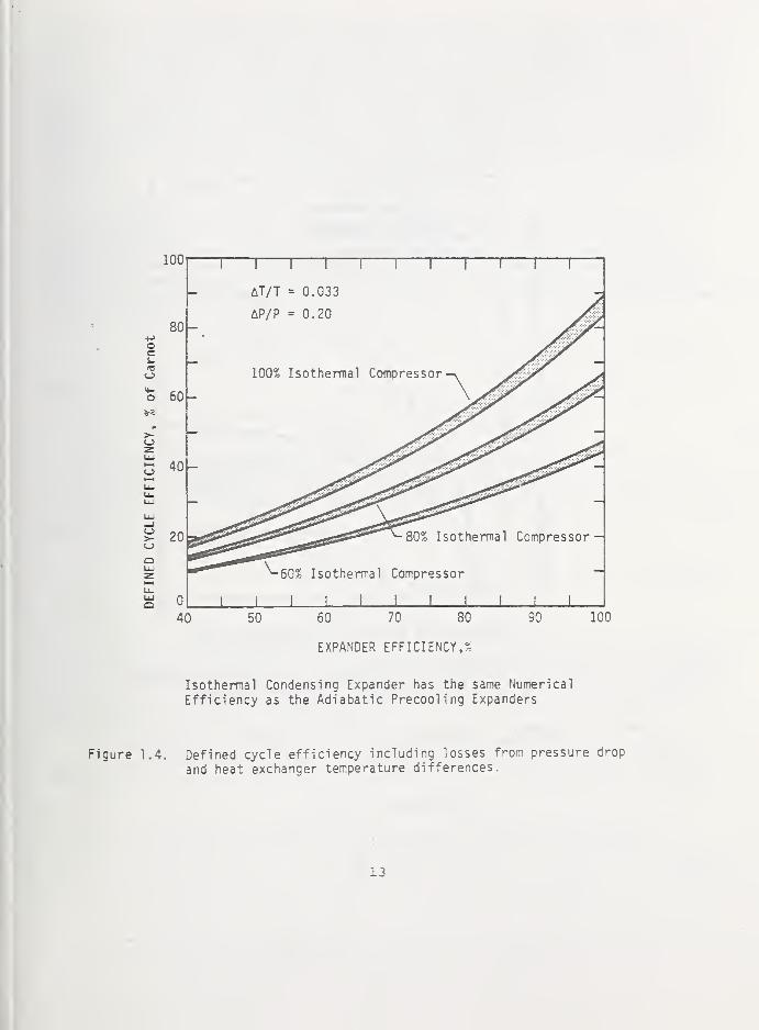
EXPANDER EFFICIENCY,?
Isothermal Condensing Expander has the sane Numerical
Efficiency as the Adiabatic Precooling Expanders
Figure 1.4. Defined cycle efficiency including losses from pressure drop
and heat exchanger temperature differences.
13

10+Jc•r-
Oa.
(U
<u
>-
o>-
<
—Ti^ = 60% of isothermal
n. = 80% of isothennal'iso
n = 80% of adiabatic'pre
T—
r
T—
r
1—
r
1—
0 20 40 60 80 100
PRESSURE RATIO ACROSS THE ISOTHERMAL EXPANDER
The Isothermal Condensing Expander and the AdiabaticPrecooling Expanders are 80 Percent Efficient
Figure 1.5. Increase in defined cycle efficiency resulting from the useof a three pressure cycle.
14

slight gains in liquefier efficiency can be achieved by using unreasonablylarge heat exchangers, and/or by substituting the more thermodynamicallyefficient expansion ejector or wet expander for the Joule-Thomson expansionvalve as the final expansion device. Maximum liquefier efficiency is achievedby removing the heat of converting normal hydrogen to parahydrogen at thehighest temperature possible and by locating the expanders to minimize heatexchanger temperature differences. Choosing between a Claude cycle, Braytoncycle, or cascade cycle is primarily a matter of providing the best pressureratios and inlet temperatures for the available compressors and expandersrather than a matter of changing the hydrogen liquefier efficiency.
1.3.1. Efficiency and losses of teal liquefier components
Efficiency is defined as the rario of ideal work to actual work for aparticular process. Losses for all components were determined using anavailability balance around the component. The sum of the losses and theideal power required to produce a unit of liquid divided by the isothermalcompressor efficiency minus the power output of the expanders resulted inthe actual power required to produce the liquid. Expressed in equation formthe actual power required to produce the liquid is
=,
- (1.3.1)c
where
actual power required to produce liquid,
total liquefier losses,
ideal power required to produce liquid,
isothermal efficiency of the compressor,
recoverable power from the expanders.
Overall liquefier efficiency becomes,
WCl
and
Wn = p
Cl
a
w .
Cl+ W .
T Cl(1.3.2)
The liquefier is 100 percent efficient when the efficiency of the compressoris 100 percent of isothermal, and the total losses in the liquefier are equalto the expander output power. In this equation (equation 1.3.2) the expanderoutput power is treated as a loss because the room temperature compressormust be large enough to supply the total expander output power plus the idealpower required to produce the liquid.
In the following sections the methods used to calculate the losses for
the various liquefier components are defined. Also, the state-of-the-artefficiencies are assigned to the components used in the practical liquefier,
1.3.1.1. Compressor
For a real gas, the ideal power required to compress a fluid is;
^ci = - '^in^'
15

where
P^^ = isothermal compressor power,
m = mass flow rate,
lb ^ = availability of the outlet fluid,^out
and = availability of the inlet fluid.
The compressor efficiency is then defined as;
= , whereac
P is the actual compressor power required by the liquefier. Compressoraclosses are determined bv;
''l-n.
L = Ac n ^out ^in
c(1.3.4)
where
= compressor losses.
and = isothermal compressor efficiency.
Compressor efficiencies are usually given in terms of the adiabatic work.Depending on the compression ratio, the isothermal efficiency of most com-pressors is 60 percent while very large compressors may approach 70 percent [8].A compressor efficiency of 60 percent of isothermal was used throughout thisstudy.
1.3.1.2. Expanders
Expander efficiency is expressed by;
Ahn = TvT- ' (1.3.5)pre Ah
s
where
ripj.g = isentropic expander efficiency.
Ah = actual specific enthalpy change across the expander,
and Ahg = isentropic specific enthalpy change across the expander.
Expander losses are determined by the difference in availability acrossthe expander or;
L = m (4^ . - ij^ ^) . (1.3.6)e ^out
Although this expander loss includes the power output of the expander, it isappropriate because room temperature compression power is required to supplythe energy (see equation (1.3.2) and its discussion). The expander powerwas recovered by reducing the actual isothermal compressor power by the totalpower from the expanders.
Expander efficiencies of 80 percent of isentropic were used for themajority of the calculations. Efficiencies of 60 and 100 percent were alsoused to determine the effect of expander efficiency on overall liquefier
16
efficiency. The 80 percent efficiency is reasonable [5] if care is taken tomatch operating pressure ratios and inlet temperatures to the characteristicsof the expander.
1.3.1.3. Joule-Thomson expansion valve
The Joule-Thomson (JT) expansion valve has an efficiency equivalent toa zero expander efficiency. Ignoring m.inor velocity effects, the zero effi-ciency results in no change in enthalpy across the valve during an expansionprocess
.
The Joule-Thom.son valve losses tend to be high because of the zero effi-ciency; however, they can be minimized by carefully selecting the operatingconditions. Losses are determined by;
'JT= m
out ) . (1.3.7)
1.3.1.4. Expansion ejector valve
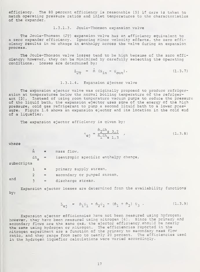
The expansion ejector valve was originally proposed to produce refriger-ation at temperatures below the normal boiling temperature of the refriger-ant [5] . Instead of using room temperature vacuum pumps to reduce the pressureof the liquid bath, the expansion ejector uses some of the energy of the highpressure, cold gas refrigerant to pum.p a second liquid bath to a lower pres-sure. Figure 1.6 shows an expansion ejector and its location in the cold endof a liquefier.
The expansion ejector efficiency is given by;
ih_Ah -,
2 s 3 , 2
m, Lh , ^1 s 1 , 3
(1. 3. 8)
where
subscripts
and
by;
m
Ah^
1
2
mass flow,
isentropic specific enthalpy change,
primary supply stream,
secondary or pumped stream,
discharge stream.
Expansion ejector losses are determined from the availability functions
L . = m,4^, + m-jii)-, - (m. + m-,) ^r, • (1.3.9)ej 11 2 2 1 2 3
Expansion ejector efficiencies have not been measured using hydrogen;however, they have been measured using nitrogen [6] . Since the primary andsecondary flows are the same gas, the ejector efficiency should be nearlythe same using hydrogen or nitrogen. The efficiencies reported in thenitrogen experiment are a function of the primary to secondary mass flow
ratio, and they range from zero to nearly 20 percent. The efficiencies usedin the hydrogen liquefier calculations were varied accordingly.
17

EXPANSION EJECTOR
Figure 1.6. An expansion ejector and a cold end using the ejector.
18

1.3.1.5. Heat elxchangers
Selecting the proper counterflow heat exchanger involves a balance be-tween the cost of energy to produce the liquid and the capital cost of theexchanger. Decreasing the heat exchanger temperature difference improvesthe liquefier efficiency but may result in a large and overly expensiveexchanger. Thus, the size of each exchanger was calculated based on assignedend point temperatures. If any heat exchanger in the liquefier was unreasonablysmall or large, the end point temperatures were reassigned and the liquefierefficiency recalculated.
Heat exchanger size was determined using a method described by Daney [7].He based the heat exchanger size on the numerical value of AU/m found from;
where
AU dhW =(AT,) da '
(1.3.10)
A = heat transfer area on one side of the counterflow heat ex-changer,
U = overall heat transfer coefficient,
A = mass flow rate on one side of the exchanger,
dh = change in specific enthalpy on one side of the exchanger,
AT = local heat exchanger temperature difference.
and
da = dA/A.
The local heat exchanger temperature differences for 20 points along thelength of the exchanger were used to numerically integrate the right side ofthe above equation.
The heat exchanger size was varied from 300 to 1000 J/ (mol K) in thestudy. These sizes provided a good balance between the capital cost andlosses for the heat exchangers.
1.3.2, Real hydrogen liquefier cycle
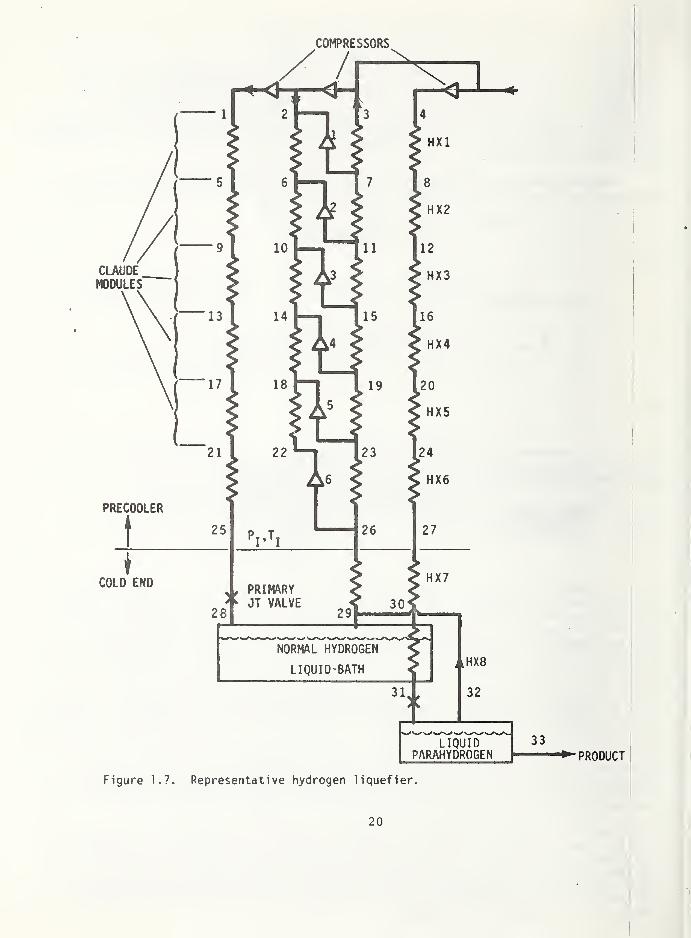
A schematic for a representative hydrogen liquefier is shown in figure1.7 and the corresponding fluid states are given in table 1.1. Many othercombinations and numbers of Claude and Brayton modules were investigated,but this liquefier (with six precooling expanders in Claude modules and a
Joule-Thomson (JT) valve as the final expansion device) is taken as typical.The fluid states shown in table 1.1 show the heat exchanger temperature dif-ferences and pressure drops. The product stream (4, 8, 12, etc.) is at a
sufficient pressure to condense in the normal hydrogen liquid bath and it ismaintained at equilibrium ortho-para concentration as it is cooled. The pri-mary JT expansion valve is supplied by a separate compressor with the pressureand temperature at point 25 adjusted for maximum liquefier efficiency. Therefrigerant supply pressure (point 2) is selected to eliminate the intermediateheat exchangers between the modules, i,e, the inlet temperature of a followingexpander is nearly the same as the discharge temperature of a preceding ex-pander. Eliminating the intermediate heat exchangers increases liquefierefficiency since the temperature differences of the remaining exchangers areinfluenced less by unbalanced flows, variable specific heats, etc.
The precooler refrigerant is normal hydrogen (streams 1, 2 and 3) exceptfor the small amount of parahydrogen mixed into the returning low pressurerefrigerant (point 29). The increased parahydrogen content is accounted forin the precooler return flow but is converted back to normal hydrogen in theroom temperature compressor. Because of the relatively low parahydrogen flowat point 32, the back conversion assumption has an insignificant effect onthe overall liquefier efficiency.
19
COMPRESSORS
LIQUIDPARAHYDROGEN
Figure 1.7. Representative hydrogen liquefier.
20

Table 1.1 Fluid states for example hydrogen llquefier (figure 1.2).
PT P T
K
H
J/ Cp
S
* nio 1
)
J/(g-raol-k)
m ParaContent
°//o
1 15.923 300 8534.483 119,,2315 6926,.237 1,.0 25
2 6.171 300 8525.816 127.,1327 4547,.207 10..2954 25
3 1.130 294.985 8521.895 140.,7698 306,. 964 11,.3205 25.16
4 1.740 300 8521.895 137.,667 1383,. 097 ,9107 25
5 15.765 209.603 5961.912 109.,126 7385,. 382 1..0 25
6 6.109 209.603 5960.620 117.,057 5004,.652 9..1791 25
7 1.142 206.099 5863.111 130.561 855
,
. 996 10..2040 25.18
8 1.723 209.603 5957.341 127.,591 1841.. 142 ,9107 equil.
9 15.609 143.360 4190.847 99.,077 8628,.977 1,,0 25
10 6.048 143.360 4201.616 107.,079 oZ3o
,
. 929 6.,7339 25
11 1.153 140.964 4145.566 120. 493 2158..972 9.,0545 25.21
12 1,706 143.360 4166.843 117. 419 3102
.
, 158 ,9107 equil.
13 15.455 94.272 2993.868 88. 973 10463., 103 1.,0 25
14 5.988 94.272 3025.948 97. 165 8037
.
, 805 6.,7339 25
15 1.165 92.696 3004.547 110. 542 4003.,066 7.,7588 25.24
16 1.689 94.272 2829.978 106. 051 5175., 835 9107 equil.
17 15.302 59.686 2183.928 78. 335 12844., 752 1.,0 25
18 5.928 59.686 2258.297 87. 112 10285
.
, 832 5. 0460 25
19 1.176 58.688 2269.863 ICQ. 611 6247
.
,654 6. 0709 25.31
20 1.672 59.686 1713.571 91. 243 8501.,981 9107 equil
.
21 15.150 38.352 1565.074 65. 318 16130., 801 1. 0 25
22 5.869 38.352 1767.462 76. 972 12838.,948 3. 0932 25
23 1.188 36.525 1797.070 90. 437 . 8827
.
,278 4. 1181 25.45
24 1.656 38.352 908.545 74. 647 12675
.
, 599 9107 equil
.
25 15.0 24.066 651.222 37. 344 23609
.
, 245 1. 0 25
26 1.2 22.970 1476.127 79. 753 11711
.
305 1. 0248 26.82
27 1.639 24.066 460.745 60. 265 1 £ c / o16542
.
322 9107 equil.
28 1.212 20.944 651.222 39. 455 22975. 845 1. 0 25
29 1.212 20.944 1451.586 77. 671 12311. 629 1. 0 25
30 1.623 22.030 404.123 57. 881 17201. 106 9107 equil
.
31 1.607 21.991 -474.703 17. 992 28288. 859 9107 equil
.
32 1.212 20.962 389.344 59. 313 16756. 521 0248 100
33 1.218 20.962 -498.958 16. 918 28586. 829 8858 100
21
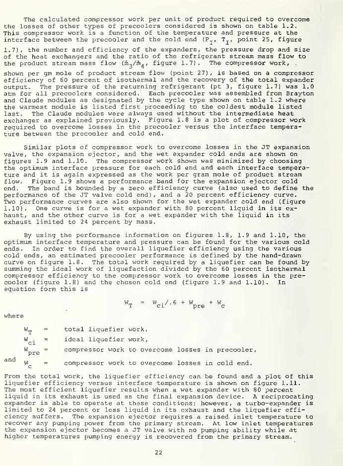
The calculated compressor work per unit of product required to overcomethe losses of other types of precoolers considered is shown on table 1.2.This compressor work is a function of the temperature and pressure at theinterface between the precooler and the cold end (P^, T^, point 25, figure
1.7), the number and efficiency of the expanders, the pressure drop and sizeof the heat exchangers and the ratio of the refrigerant stream mass flow tothe product stream mass flow (m^/ih^ , figure 1.7). The compressor work, ,
shown per gm mole of product stream flow (point 27) , is based on a compressorefficiency of 60 percent of isothermal and the recovery of the total expanderoutput. The pressure of the returning refrigerant (pt 3, figure 1.7) was 1.0atm for all precoolers considered. Each precooler was assembled from Braytonand Claude modules as designated by the cycle type shown on table 1.2 wherethe warmest module is listed first proceeding to the coldest module listedlast. The Claude modules were always used without the intermediate heatexchanger as explained previously. Figure 1.8 is a plot of compressor workrequired to overcome losses in the precooler versus the interface tempera-ture between the precooler and cold end.
Similar plots of compressor work to overcome losses in the JT expansionvalve, the expansion ejector, and the wet expander cold ends are shown onfigures 1.9 and 1.10. The compressor work shown was minimized by choosingthe optimum interface pressure for each cold end and each interface tempera-ture and it is again expressed as the work per gram mole of product streamflow. Figure 1.9 shows a performance band for the expansion ejector coldend. The band is bounded by a zero efficiency curve (also used to define theperformance of the JT valve cold end) , and a 20 percent efficiency curve.Two performance curves are also shown for the wet expander cold end (figure1.10). One curve is for a wet expander with 80 percent liquid in its ex-haust, and the other curve is for a wet expander with the liquid in itsexhaust limited to 24 percent by mass.
By using the performance information on figures 1.8, 1.9 and 1.10, theoptimum interface temperature and pressure can be found for the various coldends. In order to find the overall liquefier efficiency using the variouscold ends, an estimated precooler performance is defined by the hand-drawncurve on figure 1.8. The total work required by a liquefier can be found bysumming the ideal work of liquefaction divided by the 60 percent isothermalcompressor efficiency to the compressor work to overcome losses in the pre-cooler (figure 1.8) and the chosen cold end (figure 1.9 and 1.10). Inequation form this is
= W./.6+W +WT ci pre c
where
and
= total liquefier work,
W^^ = ideal liquefier work,
^pre~ compressor work to overcome losses in precooler,
= compressor work to overcome losses in cold end.
From the total work, the liquefier efficiency can be found and a plot of thisliquefier efficiency versus interface temperature is shown on figure 1.11.The most efficient liquefier results when a wet expander with 80 percentliquid in its exhaust is used as the final expansion device. A reciprocatingexpander is able to operate at these conditions; however, a turbo-expander islimited to 24 percent or less liquid in its exhaust and the liquefier effi-ciency suffers. The expansion ejector requires a raised inlet temperature torecover any pumping power from the primary stream. At low inlet temperaturesthe expansion ejector becomes a JT valve with no pumping ability while athigher temperatures pumping energy is recovered from the primary stream.
22

Table 1.2 Compressor work required to overcome losses for various types of precoolers.
RunI
atmI
K
No.
Exp's/Eff
,
CycleType* DPOP 1
HX2
Size3
Parameter4 5 6
Ratiom./m,3 4
Comp . Wi
for Los
J/(g- mol'K^ J/ (g'mo
1 30 34. 03 6/80 CCCCCC 0.01 511 513 532 617 394 157 . 7302 31774
2 30 34 6/80 CCCCCC 0.01 517 519 541 637 422 122 . 6578 31824
6 25 30 4/80 CCCC 0.01 668 482 437 225 34209
7 20 30. 25 4/80 CCCC 0. 01 672 484 438 348 .7769 34262
8 10 32.
5
6/80 ^ f>^CCCCCC 0. 01 587 585 607 690 572 89 . 2358 31187
9 10 32.5 6/80 CCCCCC 0. 01 593 591 611 684 528 108 . 2436 33273
11 15 30 6/80 CCCCCC 0. 01 563 560 572 622 354 380 .6982 34362
13 15 24 6/80 CCCCCC 0.01 599 597 585 704 414 113 . 8858 35825
20 30 34.1 6/80 CCCCCC 0.01 510 512 531 615 392 158 . 7270 31360
25 30 34 6/80 CCCCCC 0.01 510 511 530 613 401 165 .5889 33702
26 30 34 6/80 CCCCCC 0. 01 510 511 529 612 399 163 .5910 33684
27 30 34 4/80 CCCC 0.01 775 851 645 806 . 5889 31693
28 30 34 4/80 CCCC 0.01 775 857 646 805 . 5867 31712
29 20 30.2 4/80 BBBC 0.01 317 223 171 101 . 7769 35845
32 7 35.3 4/80 BBBC 0.01 680 587 441 627 .2204 28859
33 7 35.3 4/80 BBBC 0.02 680 587 441 575 .2173 32527
34 5 36 4/80 BBBB 0.01 615 522 382 297 .1631 29001
35 5 36 5/80 BBBBB 0.01 586 524 421 324 277 .1631 27186
36 5 36 6/80 BBBBBB 0.01 561 516 442 355 289 263 .1631 26291
37 30 34 4/80 CCCC 0.01 775 859 646 456 .5359 3088S
38 30 34 4/60 CCCC 0.01 686 621 716 538 .5384 67707
41 15 24 6/60 CCCCCC 0.01 572 568 587 683 442 173 .8858 71485
* C designates a Claude module and a B designates a Bray ton module.

38.000 1—
36.000 —
- 34.000o£
a 32J0OOo
0£Oto(/i
la
30JOOO
o
28.000
26.000
Compressor Efficiency = 60 % of Isothermal
Expander Efficiency = 80 % of Adiabatic
V 02911 ,
\ 09**26
O33
28>^227
08 A2O
37\
034
O32
0 35
11
10 36 1
1
20 25 30 35 40
INTERFACE TEMPERATURE, K
45
Figure 1.8. Compressor work required to overcome losses in the pre-
cooler for various cycles and interface temperatures.
24

10,000 r—
8000
oE
6000
WORK,
:ssoR
4000
COMPRf
2000
24
COht'RESSOR EFFIC1ENCY=60% of ISOTHERMAL
0 % Efficient Ejector
and JT Valve
20 % Efficient Ejector
26 28
INTERFACE TEMPERATURE, K
25

30 35 40 45 50
INTERFACE TEMPERATURE, K
Figure 1.10. Compressor work required to overcome losses in
a wet expander cold end for various interface
temperatures.
26

36Compressor Efficiency = 60 % of isothermal
Expander Efficiency = 80 X of isentropic
35
3
34u
a.
>-
zUJ
C3 33»—
^
u.u.tu
32
Wet expander; Liquid in
discharge is 80 % of total
di scharge flow.
Expansion ejector
Efficiency = 20%
Joule Thomson expansion valve
Wet expander; Liquid in
discharge limited to 24 % of total
di scharge f 1 ow.
31
3020 25 30 35
INTERFACE TEMPERATURE, K
40 45
Figure 1.11. Hydrogen liquefler efficiency using a wet expander, expansionejector or a Joule Thomson valve final expansion device versusthe interface temperature.
27

Because the losses in the cold end are a small percentage of the totalliquefier losses, only a small advantage is gained by substituting a wetexpander or expansion ejector for a JT valve in a properly optimized cycle.
Tables 1.3 and 1.4 show the losses for the representative liquefier.The liquefier efficiency is 33.24 percent of Carnot with the majority of thelosses occurring in the compressors and expanders. The JT valve losses arelow because its inlet temperature is low. Replacing the JT valve with areversible expander would increase the liquefier efficiency to 33.72 percentof Carnot.
All liquefiers which were investigated used from four to six Claude orBrayton modules in different combinations in the precooler and had nearly thesame efficiency and loss distribution as the representative liquefier.
The choice of the type of precooler did not affect efficiency but it didchange the precooler pressure ratio. Since an increased refrigeration loadon a Brayton module is absorbed by increased expander pressure ratio, thecompressor pressure ratio for the precooler of a liquefier employing mostlyBrayton modules tended to be high. On the other hand, the Claude moduleabsorbs the refrigeration load by increased expander flow and the compressorpressure ratio is determined solely by the number of expanders (when theexpanders are placed so the discharge temperature of a preceding expander isnearly the same as a following expander). Thus, the compressor pressureratio for the precooler of a liquefier using six or more Claude modulestended to be low.
Besides the Claude and Brayton modules, a separate nitrogen refrigeratorcan be used to precool the product stream (cascade cycle) . A liquid nitrogenmodule using a JT valve as the final expansion device was compared to an allhydrogen Claude module precooling the same product stream. Figure 1.12 showsthe schematics of the two modules. Identical losses above the inlet tempera-ture of the two modules were assumed. The losses in the Joule-Thomsonnitrogen module were determined and then the expander efficiency required toproduce the same losses in the Claude module was determined. If expanderpower is not recovered, the expander efficiency required to achieve identicallosses between the two modules is 85.8 percent.
Figure 1.13 shows the room temperature compressor work required to coolthe product stream for the two systems if the expander power is recovered.These results show that when expanders with efficiencies below about 75percent are available, the best overall liquefier efficiency would beachieved with a cascade cycle. This conclusion must be qualified, however,because sufficient fluids are not available to provide the close precoolingtemperatures assumed in the example. This is especially true for tempera-tures below the normal boiling temperature of liquid nitrogen where expandersare required in the hydrogen liquefier to achieve high efficiencies. Othermore practical reasons may suggest the use of liquid nitrogen precooling: 1)
it may be possible to obtain higher efficiency expanders and compressors fornitrogen than hydrogen. Consequently, even though the warm temperatureportions of the nitrogen precooling cycle are identical with an all-expanderhydrogen cycle, lower losses will result from the higher component effici-encies; 2) liquid nitrogen may be required to purify the gaseous hydrogensupply. Since a nitrogen liquefier is required anyway, it can be increasedin size to provide precooling to the hydrogen liquefier. Other than these tworeasons, no particular gain in efficiency is provided by using liquid nitro-gen precooling.
28

Table 1.3 Individual component losses and turbine workfor the representative liquefier.
HX No.
1
2
3
4
5
6
7
Totals
E^ander No.
1
2
3
4
5
6
Totals
JT Valves
Other Cold End
Totals
Size Parameter
J/ (g'mol'k)
599.25
597.61
621.19
704.61
414.12
113.73
43.93
Efficiency
Z
80
80
80
80
80
80
HEAT EXCHANGERS
Losses
J/ (g'mol* liquid)
1286.628
1120.766
972.130
746.017
770.293
989. 732
142.045
Total Losses
J/ (g'mol'liquid)
6027.610 6027.610
EXPANDERS
Work Produced
J/ (g'nol* liquid)
3355.308
2355.252
1750. 861
1440.650
1016.764
1017.328
10936.163
COLD END
Losses
J/ (g'Eol* liquid)
4651.460
3692.622
3270.314
3410.956
3215.289
3930.506
22171.147
740.816
640.107
1380.923
TOTAL LOSSES
22171.147
1380.923
29579.680
Table 1.4 Work requirements for the representative liquefier.
Work Required Percent of
J/ (g'mol'liquid) Total
Compressor Losses (60 percent isothermal compressor) 38777.673 45.09
Expander Losses (80 percent of isentropic efficiency) 22171.147 25.78
Heat Exchanger Losses 6027.610 7.01
Cold End Losses 1380.923 1.60
Ideal Power Requirements 28586.830 33. 24*
Total 96944.183 112.72
- Expander Power - 10936.163 - 12.72
Total Liquefier Power Requirements 86008.020 100.00

Pt P T
atm K
1 51 130
2 1 128
3 1 130
4 1 78.76
Pt
1
2
3
4
P
atm
Varies
1
1
1
TK
130.00
128.00
130.00
78.76
Pressure at point 1 varies from 6.8 to 34 atm depending
on the efficiency of the expander.
Figure 1.12. A nitrogen module with a JT valve and an all hydrogen Claudemodule cooling the same product stream.
30

3000
2500
oE
o
2000 — JT System
o^ 1500
oooUJ0£
orUJ
1000
500
60 % Isothermal
Compressor
— JT System
80 % Isothermal
Compressor
Expander
System
0 20 40 60 80 100
EXPANDER EFFICIENCY IN CLAUDE CYCLE, percent
Figure 1.13. The Claude module expander efficeincy required to provide equal
performance between the Claude module and the nitrogen module
using a JT valve.
31

1.3.2.1. The aesign of a practical hydrogen Liquefier
Of the many cycles shown on table 1.2, some are not suited foruse with real expanders and compressors because of the high operating pressureratios assumed for the components. Many of the problems associated withcompressing hydrogen at room temperature using rotary compressors also applyto turbo-expanders, i.e\ low pressure ratio capability per stage. Thesepressure ratio problems become less severe as the operating temperature ofthe turbo-expanders decreases. One possible solution to the high temperatureexpander problem is to replace all the hydrogen expanders above the condensingtemperature of liquid nitrogen with a nitrogen precooler refrigerator sincenitrogen is much more amenable to expansion and compression in turbo-machinery.A theoretical study of such a cycle [8] indicates an overall hydrogen lique-fier efficiency of 36 percent which resulted from the assumed expander andcompressor efficiencies shown in table 1.5. The compressor efficiencies shownin table 1.5 are adiabatic instead of the isothermal efficiency used in thisstudy. The theoretical study of the hydrogen liquefier using nitrogen pre-cooling yielded liquefier efficiencies comparable to those determined in thisstudy for an all hydrogen liquefier.
Table 1.5 Assumed compressor and expander efficiency used to determinea hydrogen liquefier efficiency by Linde [8]
.
EfficiencyPercent Adiabatic
Nitrogen Compressor
N2 Recycle , 80
N2 Booster 65
N2 Makeup 75
Hydrogen Compressors (all) 80
Hydrogen Expanders (all) 79
Nitrogen Expanders (all) 84
A possible theoretical cycle successfully using high temperature turbo-expanders instead of nitrogen precooling in an all-hydrogen liquefier is shownin figure 1.14. This cycle would use four Brayton modules in the precoolertogether with a wet expander cold end. The interface fluid state conditionsat points 4, 5 and 6 are shown on table 1.6. These inlet conditions of thewet expander cold end result in only a slight precooler flow imbalance(mg/m^) . The low flow imbalance allows a relatively low pressure ratio acrosseach expander. Increasing the number of expanders decreases the pressureratio across each expander further as shown in figure 1.15.
Table 1.6 Interface fluid state points for theall Brayton module liquefier.
PT P(figure 1.14) atm
HJ/ (g • mol
)
J/ (g«mol«K)m
51.21.281.23
36.0035. 5136. 0021.00
1724. 691781. 36831.84
-498.15
77.00889.78374.66316.955
1. 000001.000150.163290.16314
32

33


Figure 1.16 shows the variation in liquefier efficiency as a function ofthe number of expanders. Again the liquefier efficiency is based on 80 percentisentropic expanders, 60 percent isothermal compressors, and a heat exchangersize parameter of around 500 J/(mol'K). By judicious choice of the tempera-ture level between each Brayton cycle module, the pressure ratio of eachexpander could be adjusted to exactly match its optimum operating requirements.
1.4. Comparison Between Defined Cycle and Real Gas Cycle
The calculated efficiencies of the hydrogen liquefier compare well withthe efficiencies found earlier for a defined cycle as shown on figure 1.17.Two bands are shown for the defined cycle efficiency; one band is for a constantisothermal expander efficiency of 80 percent, while the other is for a constantisothermal expander efficiency of 100 percent. The band width shows themaximum and minimum effect of pressure drop on the defined cycle efficiency.Several points show comparable calculated efficiencies for the real gasliquefier
.
The efficiencies of the theoretical defined cycle and the theoreticalreal cycle compare well even though the final expansion devices of the twocycles are quite different. The defined cycle uses a theoretical isothermalexpander as the final expansion device while the real cycle can use a Joule-Thomson expansion valve, a wet expander, or an expansion ejector. The definedcycle interface temperature - the temperature between the final expansiondevice and the precooler - is fixed at the normal boiling tem.perature ofparahydrogen . On the other hand the interface temperature for the real cycleis chosen for each final expansion device to maximize liquefier efficiency.The interface temperature of the real cycle is always greater than the normalboiling temperature of parahydrogen. Because the interface temperature ishigher for the real cycle than for the defined cycle, changing the precoolingexpander efficiencies can affect the overall efficiency of the two cyclesdifferently. When the real cycles uses a Joule-Thomson valve the interfacetemperatures are nearly the same as the defined cycle and this difference doesnot appear (see figure 1.17). But the interface temperature for a real cycleusing a wet expander or an expansion ejector is higher. In this case changingthe precooling expander efficiencies changes the liquefier efficiencydifferently which leads to a mismatch at the 60 percent precooler expanderefficiency point. However, the variance is within the bands shown onfigure 1.17.
1.5. Conclusions
The efficiency of hydrogen liquefiers is dependent upon expander effi-ciency, compressor efficiency, and to a much lesser extent on the heat ex-changer size and pressure drop. The cold end losses account for about one totwo percent .of the total compressor power, so substituting the more reversiblewet expander or expansion ejector for the Joule-Thom.son valve has littleeffect on the liquefier efficiency. The cycle efficiencies obtained in a
hydrogen gas system compare favorably with the ultimate efficiencies derivedfor a defined cycle using an ideal gas. This direct comparison reinforcesthe validity of the hydrogen gas calculations, and shows no particularpenalty due to the non-ideal characteristics of the hydrogen gas.
The type of cycle (Brayton, Claude, or Cascade) used in the liquefierhas a minimal effect on the efficiency of a hydrogen liquefier. The liquefiercycle chosen should be based primarily on using available expanders and com-pressors in their most efficient operating situations and on the economicsof using large heat exchangers with resulting low AT's and pressure drops.The Claude cycle arrangement of precooling m.odules is most amenable for usein a low pressure ratio cycle because the precooling load is absorbed by in-creasing the expander flow instead of increasing the expander pressure ratioas in the brayton cycle module. On the other hand the most efficient use of
35

315 6 7 8
NUMBER OF EXPANDERS IN PRECOOLER
Figure 1,16. Liquefier efficiency as a function of the number of Braytonmodules.
36

60 TYPE OF COLD END FOR REAL LIQUEFIER
A Wet expander 80% liquid in exhaust
PRECOOLER EXPANDER EFFICIENCY, percent
Figure 1.17. Comparison of real liquefier efficiency with the defined cycleefficiency.
37

the Claude modules (placing the expanders such that the inlet temperature ofa following expander is nearly the same as the discharge temperature of apreceding expander) requires the use of many low pressure ratio expanders tocover the temperature span required in the liquefier. For low precoolingloads (low product stream flow rates) the Brayton cycle module is particularlysuitable for centrifugal expanders because the expanders operate at raisedpressure levels with relatively low pressure ratios.
Actual liquefiers could not achieve the efficiencies determined fromany of the theoretical cycles. Among the reasons for the lower actualefficiencies are:
1. losses due to heat leak to the cold portions of the liquefier arenot included in the theoretical cycles.
2. Any input power required to purify the hydrogen supply to theliquefier has not been included.
3. A continuous equilibrium conversion from normal to parahydrogenwas assumed. In an actual liquefier the conversion would probably be non-ideal requiring removal of some of the conversion energy at temperatureslower than equilibrium. This conversion at lower temperatures would also reducethe actual liquefier efficiency.
4. Hydrogen leakage from low temperature components such as expanderswould significantly reduce overall liquefier efficiency. No leakage wasallowed in the theoretical cycles.
5. The theoretical calculations assumed the recovery of the totalexpander output power. In an actual liquefier recovery of the total expanderpower is not possible due to inefficiencies in the mechanical or electricalinterface between the expanders and the liquefier compressor.
The results of these studies indicate that with a 60 percent efficientisothermal compressor, 80 percent adiabatic precooling expanders, and an80 percent isothermal expander, the maximum liquefier efficiency attainableis 40 percent (figure 1.2). Losses due to system pressure drops and heatexchanger temperature differences reduces the defined cycle efficiency to34 percent (figure 1.3) and 30 percent (figure 1.4). A reasonable efficiencyfor a practical liquefier may lie somewhere between 30 and 34 percent withoutconsidering other losses such as heat leak to the cold components. Onewould expect that an efficiency of 30 percent may be the practical limit forliquefiers using state-of-the-art components. Very large compressors mayexhibit isothermal efficiencies approaching 70 percent; the practical limitof liquefier efficiency would then be 35 percent. Based on this analysis,the currently reported efficiencies of 30-35 percent for industrial hydrogenliquefiers show good design and optimization. Increasing the compressorand/or expander efficiency has the highest potential for increasing theoverall liquefier efficiency.
Because of the large dependence of the liquefier efficiency on compressorefficiency, a hydride compressor was investigated. The hydride compressorusing the waste heat from a primary compressor is discussed fully in the Appen-dix. The hydride compressor proved to be no more efficient than conven-tional compressors.
Since hydrogen liquefier efficiency is primarily dependent upon the ef-ficiency of the expanders and compressors, no large increase in liquefierefficiency can be expected in the near future. Both expanders and com-presrors have had a long development history, and the probability of stepincreases in their efficiency is quite remote.
38
A
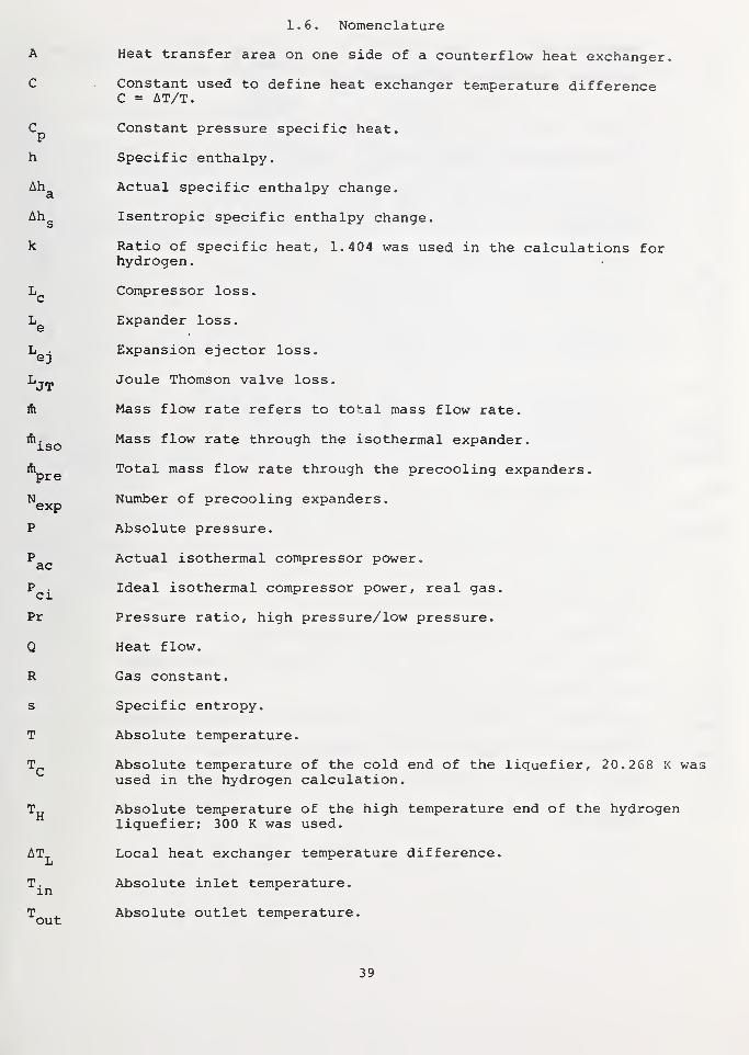
1.6. Nomenclature
Heat transfer area on one side of a counterflow heat exchanger.
C Constant used to define heat exchanger temperature differenceC = AT/T.
Cp Constant pressure specific heat.
h Specific enthalpy.
Ah^ Actual specific enthalpy change.
Ah Isentropic specific enthalpy change,s
k Ratio of specific heat, 1.404 was used in the calculations forhydrogen.
Compressor loss.
Expander loss.
Expansion ejector loss.
Lj^ Joule Thomson valve loss.
ih Mass flow rate refers to to^.al mass flow rate.
A^g^ Mass flow rate through the isothermal expander.
Ap^g Total mass flow rate through the precooling expanders.
^exp Number of precooling expanders.
P Absolute pressure.
P Actual isothermal compressor power.cLC
P . Ideal isothermal compressor power , real gas
.
Pr Pressure ratio, high pressure/low pressure.
Q Heat flow.
R Gas constant.
s Specific entropy.
T Absolute temperature.
Absolute temperature of the cold end of the liquefier, 20. 268 I< wasused in the hydrogen calculation.
Absolute temperature of the high temperature end of the hydrogenliquefier; 300 K was used.
AT^ Local heat exchanger temperature difference.
T^^ Absolute inlet temperature.
T ^ Absolute outlet temperature,out
39

T Absolute ambient temperature T = T„ in the derivation and calculation,o o H _
H CT^^ Log mean temperature difference T^^ = ~— .
In (/)C
U Overall heat transfer coefficient.
Ideal power requirements for precooling the product stream.
W2 Ideal power requirements to condense the produce stream.
W Compressor work required to overcome losses in the cold end,^ * J/(g-mol),
W Actual total compressor power,ca
W^^ Ideal liquefier power requirements.
W„ Recoverable expander power, total.
Isothermal compression power.
Wp^^ Compressor work to overcome losses in precooler.
W„ Recoverable expander power from the precooling expanders,pre
W„ Recoverable power from the isothermal expander W = 28.988 xISO C X U. ISO
p
Total liquefier work.
GreekV
a (k - l)/k
\l)Availability function of h and s.
n Isothermal efficiency used for the compressor.^ r
n Overall cycle efficiency based on minimum compressor power,
rigj Isentropic ejector efficiency.
n • Isothermal efficiency of the isothermal or coldest expander.ISO
n Isentropic efficiency of the precooling expanders.
u) Mass flow rate of the product stream, defined cycle.
X Latent heat, 28.988 K x C was used in the calculations forhydrogen. ^
40

1.7. References
[1] Parrish, W. R. and Voth, R. 0., Cost and availability of hydrogen, Nat.Bur. Stand. (U.S.) Special Publication 419, (J. Hord, Ed.) (May 1975).
[2] Collins, S. C. and Cannaday, R. L., Expansion machines for low tempera-ture processes (Oxford Univ. Press, 1966).
[3] Grassmann, Von P. and Kopp, J., On the choice of temperature differenceand heat transfer coefficient in heat exchangers, Kalletechnik 9^, No.10, 306-308 (1957).
[4] Jacobs, R. B., The efficiency of an ideal refrigerator. Advances inCryogenic Engineering
, 7_' ^- ^- Timmerhaus, pp. 567-571 (PlenumPress, Inc., New York, NY, 1962).
[5] Rietdijk, J. A., The expansion-ejector, a new device for liquefactionand refrigeration at 4 K and lower. Commission 1, International Instituteof Refrigeration (1966)
.
[6] Daney, D. E . , McConnell , P. M. and Strobridge, T. R. , Low temperaturenitrogen ejector performance. Advances in Cryogenic Engineering , 18 ,
Ed. K. D. Timmerhaus, pp. 476-485 (Plenum Press, Inc., New York, N.Y.,1973)
.
[7] Daney, D. E., Refrigeration for an 8 K to 14 K superconducting trans-mission line, Nat. Bur. Stand. vU.S.) NBSIR 74-375, (Oct. 1974).
[8] Survey study of the efficiency and economics of hydrogen liquefaction,NASA CR-132631, prepared by the Linde Division of Union Carbide Corporation,70 pages (1975)
.
[9] Cummings, D. L. and Powers, G. J., Storage of hydrogen as metal hydrides,Ind. Eng. Chem. Process Des. Develop. 13_ (2), 182 (1974).
[10] Wiswall, R. H. and Reilly, J. J., Metal hydrides for energy storage,Proc. of the 7th Intersociety Energy Conversion Engineering Conf., 1342(1972)
.
41

1.8. APPENDIX
Hydride Compressors
W. R. Parrish
1.8.1. Introduction
As pointed out in section 1.5, one way to significantly improve theliquefaction cycle efficiency is to increase compressor efficiency. Thisappendix considers the feasibility of using the waste heat generated by aconventional compressor to drive a metal hydride "compressor." Calculationsshow that there is too little high quality heat to make this hybrid compressorsystem worthwhile.
1.8.2. Properties of metal hydrides
This section gives a terse explanation of the properties of metal hy-drides; more complete details are presented elsewhere [9,10]. If certainmetals are exposed to gaseous hydrogen the following reaction takes place
M + I H2 ^ MHj^ . (Al)
The extent of this reversible reaction depends upon the pressure ofhydrogen. However, over the major portion of the reaction the equilibriumpressure remains nearly constant. This "plateau" pressure varies with tem-perature according to
In P = a + AH/RT (A2
)
where P is the pressure, a is a constant, AH is the heat of formation, i.e.hydration for eq. (Al) , R is the gas constant and T is the absolute temper-ature. For the hydride of interest here, AH is negative. This means thatthe plateau pressure increases with increasing temperature. It also impliesthat, if a constant temperature is required, heat must be removed duringhydride formation (charging) and heat must be added during dissociation (dis-charging) .
1.8.3. Hydride compressor system
Figure 1.18 shows a schematic of the compressor system considered here.Hydrogen enters the system at pressure P, and ambient temperature, part of thehydrogen (1-f) goes through a conventional compressor while the remainder, f,
goes to the hydride beds. If necessary, the flows are recombined and sentthrough another compression stage. Heat removed from the compressor is usedto heat the hydride beds. Three parallel beds are needed; while one bed isdischarging, another bed is charging. The third bed is being cooled orheated, depending upon what portion of the cycle it is in. The cold bed isbeing charged at pressure P, as the warm bed is being discharged at pressure
Assuming that no external heat is added, the maximum value of f dependsupon how much of the heat produced by the compressors can be added to the warmbed as it discharges. Table I.l shows this dependence for three differentsystems; it also shows the possible increase in efficiency of this type ofsystem. The heat duty of the compressor is calculated by assuming that all ofthe work going into the compressors is converted to heat. The compressorefficiency for estimating the heat duty is assumed to be 80 percent of adia-batic. (The heat duty calculated here for system II was five percent less
42


than that given by a more detailed compressor design for the same inlet andoutlet pressures [9]).
The fraction of heat utilized depends upon the operating temperaturerange of the compressor cooling fluid. If water is used at temperaturesbetween 80 and 200 °F, less than half of the heat could be used to keep thedischarging bed warm.
Based on table A.l it is unlikely that the hydride compressor conceptcould ever become a useful system, at least at the pressures considered here.This conclusion is independent of the type of hydride considered because ofthe chemical nature of hydrides. Ideally, one would desire the hydride tohave a low value of AH and a rapid change in pressure with temperature.However, as eq. (A2) shows, these two conditions are contradictory since theywould require the value of AH to be small and large simultaneously.
Table A.l. Results of feasibility of using hydride compressors.
Hydride MaterialI
NbH-^NbH,
SystemII
VH VH
III
^2 FeTi "trii. FeTiH
AH- kJ/a-mol H [2] -39 -40 -23
Pj^, atm. 1.0 2.8 4.7
V ^, atm. 6.8 16.7 30. 0
P^, atm. 6.8 40.0 66.7
Maximum HydrideTemperature
Bed°C ,; 71 63 64
Fraction of FlowThrough Hydride Bed, f
Apparent OverallAdiabatic Compressor Efficiency
Percent
Fraction of Com-pressor Heat PutInto DischargingHydride Bed
I
System
II III I
System
II III
0.000.250. 380. 501.00
0
0. 0360.0530. 0690.129
0 0
0.050 0.0870.074 0.1290.097 0.1690.182 0.317
8083848692
80 8083 8384 8485 8690 92
44

CHAPTER 2
RECOVERY OF HYDROGEN LIQUEFACTION ENERGY
W. R. Parrish
2 . SUMMARY
This chapter considers the technical feasibility of recovering a portionof the energy which goes into liquefying hydrogen. Three possible recoverysystems are analyzed; two of which could have direct application in theelectrical utility industry. The first system uses a liquid hydrogen pump, aheat exchanger and a room temperature expander for shaft work recovery.Depending upon the desired outlet pressure it is possible to recover over 60percent of the ideal work of liquefaction. This is the additional amount ofwork available at the use point from the use of liquid hydrogen instead ofgaseous hydrogen at 1.0 atm. Burning a fraction of the hydrogen to heat theexpander inlet gas is an unattractive option.
If the refrigerating capacity of liquid hydrogen can be utilized in anair separation plant, the energy recovery can be even greater. For example,if such a system is used to feed a hydrogen-oxygen MHD power generator, therewould be an effective energy savings of 105 percent of the ideal work ofliquefaction. However, if the system feeds a hydrogen-oxygen fuel cell onlyabout 20 percent could be recovered.
The third energy recovery system involves using hydrogen as the refrig-erant for extracting rare gases from the atmosphere. Because of the antici-pated supply and demand picture, helium is probably the only rare gas forwhich there will be a large future demand. However, calculations show thata helium recovery unit could produce at best only 10"^ moles of helium foreach mole of liquid hydrogen vaporized.
Thus, it is technically feasible to recover an appreciable fraction ofthe energy of liquefaction if energy is the desired product. This energyrecovery has the net effect of reducing the energy cost of producing liquidhydrogen; this, in turn, makes the storage of hydrogen as a liquid moreattractive. However, the concept of using liquid as the refrigerant forrecovering rare gases from the atmosphere is much less attractive.
2.1. Introduction
In the future the most probable means of storing large quantities ofenergy derived from solar and/or nuclear sources will be synthetic fuels.Based on availability, environmental and economic considerations, the mostpromising synthetic fuel is hydrogen. Three options exist for storing largequantities of molecular hydrogen: compressed gas, metal hydride and liquid.Compressed gas might be an attractive option if depleted oil and gas fieldsare available; metal hydride technology is advancing rapidly but both thetechnical and economic feasibility still are unproven. Of the three options,only liquid hydrogen offers proven storage technology which makes it a strongcontender in many potential applications.
However, a major drawback to storing hydrogen as a liquid is the amountof energy required for liquefaction; the ideal work of liquefaction is 28.7KJ/g-mol or roughly 10 percent of the lower heating value of hydrogen. Due toliquefier inefficiencies, the actual work of liquefaction is roughly threetimes greater than ideal [1] .
Any liquefaction energy recovered would have the net effect of loweringthe energy cost of producing liquid hydrogen. This paper investigates thefeasibility of recovering a portion of the liquefaction energy as previously
45

suggested [2]. Three types of systems are considered. The first type util-izes the refrigeration capacity of liquid hydrogen for three electrical powergenerators: gas turbines, fuel cells and MHD generators; the applications aredirected toward (but not restricted to) the electrical utilities because theyrepresent a potentially large consumer of hydrogen. The feasibility of usingliquid hydrogen as the primary refrigerant for separating air and for re-covering rare gases from the atmosphere are also evaluated.
2.2. Electrical Utility Applications
2.2.1. Liquefaction energy recovery factor
To measure the benefit of recovering liquefaction energy we define theLiquefaction Energy Recovery Factor (LERF) as
LERF = (E^ - E^/^)/Elj (2.1)
where E^ is the electrical power output per g-mol of hydrogen with lique-
faction energy recovery, E^/q is the power output without recovering lique-
faction energy and E is the ideal work of liquefying one g-mol of hydrogen.Ltd.
The liquefaction energy recovery factor based on actual work of liquefactionis obtained by multiplying eq. (2.1) by the efficiency of liquefaction plantsrelative to the Carnot efficiency. The efficiency of large liquefactionplants is expected to range from 33 to 40 percent.
To keep the calculations on a common basis the values in eq. (2.1) arecalculated on the assumption that the fuel enters the system at 1.0 atm.Therefore E.. is based on 1.0 atm suction pressure as is E likewise, the
LI w/ovalues of E^ are based on 1.0 atm liquid entering the recovery system. If the
electrical power generator operates above 1.0 atm, the work of compressinghydrogen to the Operating pressure is accounted for in E^^^ by assuming a
hydrogen compressor operating at 60 percent efficiency based on isothermalcompression. If the recovery system is a net producer of shaft work it isassumed that this work is converted to electrical energy at a 95 percentefficiency.
2.2.2. Liquefaction energy recovery systems
This section considers two classes of liquefaction energy recovery sys-tems. The first takes advantage of the difference in shaft work required tocompress a liquid as compared to a gas; however, the refrigeration capabilityis wasted. The second type of recovery system makes direct use of net shaftwork and the refrigeration capacity of liquid hydrogen.
Figure 2.1 shows a schematic of the first kind of energy recovery system.Liquid hydrogen is compressed to some intermediate pressure P^, warmed to
ambient temperature and then expanded to a given final pressure which is
equal to the inlet pressure of the power generator; both the liquid pump andexpander are assumed to operate at an efficiency of 80 percent of adiabatic.The shaft work is converted to electricity and the hydrogen is sent to thepower generator. Also, it is possible to heat the high pressure hydrogen priorto expansion by burning some fraction f of the hydrogen leaving the expander.
Figure 2.2 shows values of LERF for f = 0.0 as a function of expanderinlet and outlet pressure. The calculations are based on the thermodynamicdata of McCarty and Weber [3] . For the case when the expander inlet andoutlet pressures are equal (i.e., no expander is used) the value of LERF showsthe energy saved by compressing liquid instead of gaseous hydrogen. The
46

oD. CO
0-=> II
—1
o
QJ
fO
III
o>>aii- QJ<u
en
oT
—
(J
<*-
o;
O"
^—
cOi
os-T3
in
o>1i.
Oi>o(Ja>s-
•t->
i-
o-
BOi
__
t->_
(/I
>, n3
1/)
1+-
o
oU
ma "Oa> cu1/1
47

Expander efficiency = 80% of adiabatic
Pump efficiency = 80% of adiabatic
f = 0.0
Expander outlet pressure. 30 atm
20
10
Denotes LERF without expander
L100 200
EXPANDER INLET PRESSURE, atm
300
LERF as a function of expander inlet and outlet Pressures for
the pump-expander system.
48

curves show an asymptotic behavior with increasing expander inlet pressureand, as one would expect, the relative gain with increasing inlet pressuredecreases with increasing expander outlet pressure. There is little advantagein an expander system if the outlet is greater than 20 atm; however, theenergy savings of compressing liquid instead of gas are significant at thehigher pressures. It is expected that ^2~'^2 generators will operate at30 atm [9] while fuel cells will operate very close to ambient pressure.
If all of the hydrogen goes to the power generator (f = 0) the value ofLERF is independent of the power generator. However, if some hydrogen isburned the relative efficiencies of the burner, expander, and the powergenerator must be considered. Figure 2.3 shows how LERF varies with expanderinlet pressure and f if a gas turbine having an efficiency of 28 percent(based on LHV) is used. (It is assumed that the burner has an efficiency of70 percent based on LHV) . In this case the expander outlet pressure is 8 atmwhich corresponds to present-day gas turbines [4]. For expander inlet pres-sures of less than 115 atm it is better not to burn any hydrogen; higher inletpressures make burning only a slightly beneficial option. Over the range ofvalues considered here, LERF is nearly a linear function of f. Therefore theoptimum value of f would be the value of f corresponding to the maximum tem-perature allowed in the burner. Even though there is little benefit in burn-ing some of the hydrogen, figure 2.3 shows that it is possible to obtain aLERF of 40 percent by recovering shaft work only.
Similar calculations for two other power generators, MHD and fuel cells,show that, at expander inlet pressures of 200 atm or less, it is better tosend all of the hydrogen to the power generator; this is because they are moreefficient than the burner-expander system. Therefore, it is apparent thatburning hydrogen is not generally an attractive option.
In the above calculations the refrigerating capacity of liquid hydrogenwas wasted. Liquid hydrogen could be put to the same uses as are being con-sidered for LNG "cold" [5]. However, liquid hydrogen is a more useful re-frigerant because of its lower temperature (liquid hydrogen boils at 20 Kwhile LNG boils at 112 K or higher) . One obvious application is to use liquidhydrogen as a coolant in an air separation plant. The ability to producegaseous oxygen on-site could have energy, economic and environmental benefits.Assuming an ideal, i.e. reversible, process it would be possible to produce astoichiometric quantity of oxygen from air by recovering the ideal work ofliquefaction for hydrogen without any additional work. A more detailed, andlengthy, analysis (more details are given in the Appendix) shows that at best,only 40 percent of the stoichiometric could be produced without additionalwork. Thus additional work is required if a stoichiometric amount of oxygenis desired. Even so, the more realistic calculations point out the followingadvantages for using liquid hydrogen as a refrigerant in an air plant:
1. Based on the ideal work of separation (6100 J/g-mol of gaseous 0^product) , it is possible to obtain an efficiency of 18 percent for an airplant using a single distillation column. This can be compared to theefficiency of 10 to 12 percent reported by Bliss and Dodge [6] for con-ventional single column plants and 19 percent for large dual column airplants as given by Springmann [7].
2. If the column could be operated at 0.33 atm, the efficiency couldincrease tonearly 34 percent.
3. If high pressure gaseous oxygen is the desired product, using liquidhydrogen as a coolant makes it attractive to compress liquid instead ofgaseous oxygen. Smith [8] has pointed out that it is normally unattrac-tive to pump liquid oxygen to provide high pressure gaseous oxygen in a
conventional air separation plant; however, liquid hydrogen coolingprovides enough refrigeration capacity at 90 K to permit the liquidoxygen to be pumped and expanded to produce net shaft work as earlierdescribed for hydrogen.
49

0.5
0.4
0£oC_)
>-
Oo
>-
LU
0.3
0.2
oUi
Cr
0.1
No advantage
to burn H
f = 0.00
Slight advantage
to burn
Expander outlet pressure = 8 atm
Burner efficiency = 70% (LHV)
Expander efficiency = 80% of adiabatic
Pump efficiency = 80% of adiabatic
Gas turbine efficiency = 28% (LHV)
100 200
EXPANDER INLET PRESSURE, atm
300
FIGURE 2.3 LERF as a function of expander inlet pressure and mass fraction
burned for a pump-expander system in conjuntion with a gas
turbine.50

Table 2.1 shows the relative benefits of recovering hydrogen liquefactionenergy, with and without utilizing refrigeration, for the MHD generator andfuel cell. The gas turbine option was omitted because gas turbines normallyuse air. The values of LERF are based on an expander inlet pressure of 200atm for both hydrogen and oxygen. The calculations for the MHD generator arebased on data by Seikel, et.al. [9] for their "option 3" ^2~'^2 ^y^^^^' their
systems are based on using an air separation plant and on operating thecombustor at 30 atm. For this case substantial gains in overall efficiency canbe made by using just shaft work as well as shaft work plus refrigeration. Inthe latter case a LERF value of 0.98 represents one-third of actual energy ofliquefaction and a substantial energy saving. There is little benefit frompumping and expanding oxygen because the expander outlet pressure is so high.From an economic standpoint, liquefaction energy recovery should be veryattractive since an air separation plant is already required.
The results are quite different in the case of fuel cells. Even afterconsidering the increased efficiency of the ^2~'^2 ^^^^ cell over the H2-air
fuel cell, there is an insufficient gain in LERF to justify using the liquidhydrogen for separating air. Even so, to conserve energy it still would beworthwhile to recover the available shaft work.
2.3. Recovery of Rare Gases
The atmosphere is the primary source of all the rare gases except helium,which currently is extracted from natural gas. Table 2.2 gives the approxi-mate atmospheric concentrations of the rare gases. The concentrations ofneon, krypton and xenon are quite low but the comnercial demand for thesegases is also low. Therefore, conventional air plants equipped with recoverysystems can produce a sufficient supply of these gases. However, the situ-ation for helium is quite different. Helium is in greater demand than theother rare gases and its demand could significantly increase if there islarge-scale implementation of high temperature gas reactors, superconductingtransmission lines and/or superconducting magnetic energy storage devices.However, natural gas reserves are depleting rapidly which means that sometimein the future, air will become the primary source of helium. Therefore, thefollowing section considers the feasibility of using liquid hydrogen as a
refrigerant for recovering helium from the atmosphere.
Table 2.1. Estimated values of LERF (liquefaction energy recovery factors)for MHD generator and fuel cell based on a 200 atm expander inlet pressure.
NO SHAFT WORK FROM OXYGEN
MHD"^ Fuel Cell^
Shaft Work Only 0.58 0.17
Shaft Work + Refrigeration
1 atm column 0.98 0.181/3 atm column 1.26 0.45
SHAFT WORK FROM OXYGEN
H2 Shaft v;ork Only 0.63
H2 Shaft Work + Refrigeration
1 atm column 1.04 0.341/3 atm column 1.31 0.61
^MHD Generator n = 0.65 based on LHV [9].
^Fuel Cell n = 0.51 for H2-air and 0.58 for H2-O2 [10].
51

Table 2.2. Atmospheric concentration of the rare gases [11]
•
Component Composition, ppm by volume
NeonHeliumKryptonXenon
185
1
0.09
2.3.1. Helium recovery process
The most attractive way to recover helium from air is to condense airunder several atmospheres of pressure and at a temperature of 64 to 70 K.
Under these conditions the vapor phase will contain roughly 25-40 percentnitrogen, 46-55 percent neon, 15-20 percent helium and 1-4 percent hydrogen[12]; depending upon the temperature and pressure, there could also be 1-4percent oxygen. The hydrogen and oxygen are removed first using a deoxoreactor. Then the enriched vapor goes to an adsorbant bed operating at 77 Kwhich removes the nitrogen and neon [11, 12].
To estimate the technical feasibility of recovering helium with the aboveprocess the practical amount of air throughput per unit of hydrogen vaporizedmust be considered. Two possible limitations exist. One is a work limita-tion, i.e. how much air that can be compressed using an expander system forhydrogen as described in section 2.2.2. The other possible limitation is inhow much air can be processed for the given amount of refrigeration available.
It is assumed here that the helium recovery system will be self-suffi-cient in energy, i.e. all the necessary shaft work will be derived from gasexpanders. If liquid hydrogen is compressed to 200 atm, warmed to room tem-perature and expanded back to 1.0 atm, there is a net energy output of roughly5040 J/g-mol H^. Then the amount of air compressed is given by
where P is the air compressor outlet pressure in atm. This equation assumes:
1. An air compressor efficiency of 60 percent of isothermal.
2. An expander efficiency of 60 percent of isothermal for the air beingdischarged from the system; this recovers some of shaft work of thecompressor
.
3. Gas compression at 300 K.
The air pressure is an operating variable but it should be as high aspossible to minimize the nitrogen content of the vapor going to the absorptionbed; the lower nitrogen content lowers the hydrogen refrigeration load. Thelowest practical pressure would probably be about 1.5 atm. Equation (2.2)then gives 4.7 moles of air per mole of hydrogen. For this case if all of thehelium was recovered there would be only 23 x 10"^ moles of helium producedper mole of hydrogen vaporized.
However, the work limitation can, in principle, be eliminated by com-pressing the liquid air, warming and expanding it back to 1.0 atm. By usingthe above assumptions and by assuming that: 1) air behaves like nitrogen, 2)the pump and expander efficiencies are 80 percent of adiabatic and 3) theexpander inlet pressure is 200 atm, one obtains
2.3.2. Work limitations
Moles of air compressedMoles of H- vaporized 1.9/ln P (2.2)
52

Moles of air compressed _ 5040Moles of H2 vaporized 3837 In P-4100 U.i)
Thus, if the air pressure is 2.9 atm, the air expander system could provideall of the compressor work.
2.3.3. Refrigeration limitations
There are three areas of the helium recovery system where the amount ofair processed could be limited by the available refrigeration. The first areais in removing the heat of absorption for neon and nitrogen. Secondly, if theair is to be compressed and expanded to provide shaft work the air stream willbe warmed by several degrees Kelvin; the hydrogen must then supply this lostrefrigeration. Lastly, the heat exchanger which cools the incoming air streamwill not be 100 percent effective and the hydrogen stream must make up thedifference
.
Considering first the heat of absorption, calculations show that theratio of helium to hydrogen throughput could be roughly 0.05; thus, this wouldnot be a limitation. Taking only the loss of refrigeration due to air com-pression into account, the maximum air throughput rationcould be only 1.5.Also, if the heat exchanger has an effectiveness of 0.95, one again obtains amaximum throughput ratio of 1.5. Therefore, one must conclude that the maxi-mum air to hydrogen throughput ratio is roughly 1.5; this implies that at bestit be possible to recover only about 7 x 10~6 moles of helium per mole ofhydrogen vaporized.
2.4. Conclusions
2.4.1. Utility application
Analysis of two types of recovery systems show that it is technicallyfeasible to recover roughly one-third to one-half of the actual energy re-quired for liquefying hydrogen; this, in effect, represents a cost credit forliquid hydrogen. Using shaft work only (neglecting the refrigeration capacityof liquid hydrogen) , 20 to 25 percent of actual liquefaction energy can berecovered.
The biggest energy savings can be obtained if the power generating unitis a MHD generator; recovery of shaft work is attractive for gas turbinesystems and, to a lesser extent, for fuel cells.
The results given here clearly show that economic analyses will be justifiedwhen hydrogen becomes an important synthetic fuel.
2.4.2. Rare gas recovery
Based on supply and demand considerations the only rare gas which wouldbe worth recovering from the atmosphere is helium. However, refrigerationcapacity limits the ratio of helium recovered to hydrogen vaporized to theorder of 10~5. Therefore, this recovery system could not be feasible unlessthe cost of helium becomes extremely expensive and the demand remains high.
53

2.5. References
[I] Strobridge, T. R. , Cryogenic refrigerators - an updated survey, Nat.Bur. Stand. (U.S.) Tech. Note 655 (June 1974).
[2] Selected Topics on Hydrogen Fuel, Ed. J. Hord, Nat. Bur. Stand. (U.S.)Special Publication 419 (May 1975).
[3] McCarty, R. D. and Weber, L. A., Thermophysical properties of parahy-drogen from the freezing line to 5000 R for pressures to 10,000 PSIA,Nat. Bur. Stand. (U.S.) Tech. Note 617 (April 1972).
[4] Griffin, L., Piiblic Service Company of Colorado, Denver, Colorado,private communication (December 1974)
.
[5] Chansky, S. H. and Haley, H. E. , The utilization of LNG cold. Paper 68-D31 presented at the 1968 American Gas Association Operating SectionDistribution Conf.
[6] Bliss, H. and Dodge, B. F. , Oxygen manufacture - thermodynamic analysesof processes depending on low temperature distillation of air. Part II,Chem. Eng. Prog. 45 (2), 129 (February 1949).
[7] Springmann, H. , Large air separation unit plants, ASME Paper 74-WAPID-8(December 1974 )
.
[8] Smith, D. E. , Comparison of liquid pumping and gas compression in gas-producing oxygen plants. Book, Advances in Cryogenic Engineering 6^, Ed.K. D. Timmerhaus, pp. 202-209, (Plenum Press, Inc., New York, N.Y.,1961)
.
[9] Seikel, G. R. , Smith, J. N. and Nichols, L. D. , H2-O2 combustion poweredsteam - MHD central power systems. Book, Hydrogen Energy, Part B, Ed. T.
N. Veziroglu, pp. 969-982, (Plehum Press, Inc., New York, N.Y., 1975).
[10] Federal Power Commission, National Power Survey, Energy DistributionResearch (to be published)
.
[II] Baron, R. , Cryogenic Systems, Book, (McGraw Hill Company, New York, N.Y.1966) .
[12] Tompkins, J. F. and Geist, J. M. , Large-scale neon recovery and purifi-cation process. Book, Advances in Cryogenic Engineering 8_, Ed. K. D.
Timmerhaus, pp. 484-488 (Plenum Press, Inc., New York, N.Y., 1963).
[13] Ruhemann, M. , The Separation of Gases, Book, (Clarendon Press, Oxford,(1949) .
[14] Bliss, H. and Dodge, B. F., Oxygen manufacture-thermodynamic analyses ofprocesses depending on low temperature distillation of air. Part I, ChemEng. Prog. 45 (1), 51 (1949).
54

2.6. APPENDIX
Air Plant Design
This appendix briefly describes the preliminary process design of an airseparation plant which uses the refrigerating capacity of liquid hydrogen.The plant is designed to produce 8 kg of 99 percent pure gaseous oxygen forevery kg of liquid hydrogen vaporized. More complete details for designingconventional air plants are given by Ruhemann [13] and by Bliss and Dodge[14] .
2.6.1. Design using an atmospheric column
Figure 2.4 shows a flowsheet for an air plant which utilizes the lique-faction energy of liquid hydrogen. The plant has one distillation columnwhich operates at 1.0 atm and is very similar to a Linde single-column airplant. Based on the results of calculations using the availability functionone would expect that air compression could be eliminated because no addi-tional refrigeration is necessary. However, more realistic calculations showthat liquid hydrogen can condense only 10 percent of the stiochiometricquantity of air. Also, heat is required in the reboiler to provide a vaporflow. Therefore, a large fraction of the air must be condensed in the columnreboiler. Because air boils at a lower temperature than oxygen, the air mustbe compressed to roughly 3.7 atm to provide a 2.5 K temperature difference inthe reboiler. Even so, this is lower than the 6.0 atm or higher required byconventional plants which derive refrigeration from gas expansion. Also, upto 40 percent of the compressor work can be obtained from the expander systemdescribed in section 2.2.2.
After the air is compressed it goes through the main heat exchanger whereit is cooled by the product streams. Due to the hydrogen flow there is a 40percent excess of refrigeration available in this exchanger; this is more thanenough to condense the water and carbon dioxide impurities in the air. Theair leaving the main heat exchanger contains 10 percent liquid; it containsone percent vapor after going through the reboiler. (To make sure there wasan adequate reboiler duty for column operation, an enthalpy-compositiondiagram was used [13]. Air was treated as a binary mixture of oxygen andnitrogen. ) The remaining vapor is condensed in the precooler and the air isexpanded to 1.0 atm through a Joule-Thompson valve. It then enters the columnas a saturated liquid.
The nitrogen-rich - stream, which contains 7 percent oxygen, leaves thecolumn as a vapor, goes through the precooler and then through the main heatexchanger (the heat duty of the precooler is based on a minimum temperaturedifference of 2 K) . The oxygen comes off of the bottom of the column as a
liquid and is compressed to the desired product pressure. It is possible tocompress the oxygen to a higher pressure and then expand the ambient temper-ature gas to the final pressure. However, the net work out of this expanderis probably too small to justify this system if the final oxygen pressure is
much greater than 1.0 atm. For these calculations, the pump was taken to be80 percent efficient based on adiabatic compression.
The liquid hydrogen is first compressed to 200 atm before going to theprecooler. It enters the precooler at roughly 28 K because it has been warmedby the compression (again assuming an 80 percent of adiabatic pump efficiency)
.
The hydrogen then goes through the main heat exchanger before it is expandedto the desired outlet pressure. The net work from the expander is used in theair compressor.
55

<u c^ Ol»-» cn
OOl t.C T3•<- >,N -C
I— -o
=j a-
•— oQ.
>>S_ C71
•I- s_
c<« Ol
o o
Q) IT3^ <*-
to O)
o cr
CM
(U

2.6.2. Subatmospheric column
The primary attraction of using a subatmospheric column is thereduction of inlet air pressure. If the column operates at 1/3 atm the inletair has to be compressed to roughly 1.6 atm to provide a 2 K temperaturedifference across the reboiler. However, this advantage is somewhat offset bythe work required to compress the nitrogen-rich stream back to 1.0 atm. Sincethe nitrogen stream should be compressed at low temperatures to minimize thework, there will be some loss of refrigeration due to compression. In fact,by assuming an 80 percent of adiabatic efficiency for the compressor, there isvery little excess refrigeration available in the main heat exchanger.
Also, it has been assumed that the air plant is leak tight; if vacuumpumps are needed, the advantage of subatmospheric operation could disappear.
57

NBS-114A (REV. 7-73)
U.S. DEPT. OF COMM.BIBLIOGRAPHIC DATA
SHEET
1. HUMl.lCA 1 ION OK HI- PORT NO.
NBSIR 77-862
2. Gov't .Accc-ssKin
No.3. Kei ipii'ni's .Accession No.
4. TlTl.F ANn SliBTITI.i;
STUDIES OF HYDROGEN LIQUEFIER EFFICIENCY AND THERECOVERY OF THE LIQUEFACTION ENERGY
5. Publ icat ion Date
6. I'^t- r [ orm 1 n i: Orc.ini/.ition Oojc
275.057. AUTHORfSi 8. Pt rl^trr.ung t^rcan. Report N\'.
9. PKRKORMINC; ORC. AN I/.AT ION NA.MH ANP ADDRF-SS
NATIONAL BUREAU OF STANDARDSDEPARTMENT OF COMMERCEWASHINGTON, D.C. 20234
10. Prouct Task «ork t n,l No.
275015311. ' onir.iLi Ciraiu No.
12. Sponsoring Ort;.in izai u>n Nami- and Complete- AJdrcs> 'Sfreef. City. Siatc. ZIP)
Same as above
13. lypt ol Kt-pori PiTio-i
C-OVl ft-
J
M. "^pon s or m ^ Acrru * o
15. SLPPl.l- MI'NTAKV NO l h.--
16. ABSTRACT (A 200-word or less tactual summary ot most si^tticant information- U document includes a sif^nilicant
bibliography or literature survey, mention it here.)
Liquid hydrogen is a potential synthetic fuel. It is nonfossil,its production and storage technology is well developed, and it isinherently nonpolluting . However, the economics of liquefying hydrogenare costly both in the energy required to produce the liquid and in thecapital costs of the liquefier. These costs could be reduced by increas-ing the liquefier efficiency and/or by recovering a portion of theliquefaction energy at the use site. This paper provides the maximumhydrogen liquefier efficiency based on the efficiency of availablecomponents and the fraction of original liquefaction energy that can berecovered at the use site. Since the inefficient compressors and ex-panders are the major cause of liquefier inefficiency, no increase inliquefier efficiency above the current 30 to 35 percent is probablewithout a corresponding increase in compressor and expander efficiency --
a difficult task since both the compressors and expanders have a longand stable history of development. However, roughly one-third to one-half of the actual energy required to liquefy hydrogen can be recoveredat the use site and this represents a cost credit for liquid hydrogen
.
17. KH"! 'I'ORHS (.SIX to twelve t-ntrifs, alphuhclicnl ardrr. . .ipi i.jI i z<' only the fir.-.l h-llrr i>l the lirst k'V uor./ unUss ./ /ro;>,r
name, separated by semicolons )
Component efficiency; cryogenics; efficiency; energy recovery; hydrogen;liquefier
.
18. A\ AI1.AHI1.1TV XX I'nlHniK-.l
[ l-or Oif.cl.il Oistnl^ution. Ho Not Release lo N l l.-^
[ Order |- rom Sup. of Hoc, U.S. (lovernment Printirij; OinceMa.shinv.ton, P.C . :o io:. SP < .ii. No. ( 1 (
XX "rder 1- rom National Trclniical Inlorni.il ion Service iN llsl'^prinj;! leld, \'irj;iiii.i 1 S
]
19. .Si t I Ki rV ( i.AsS1 1 RPPORT'
iNt 1. Assu- ii;n
21. NO. Ol- P M,l S
20. >\ ' run ^ ( i.as.s
riiis PA(,io
1 N( i.ASvll 11 |i
22. Pru e
S5.25
6 ^3 4


UfRT
JUNE BO