INDENTRON - NEWAGE Hardness Testers
16
INDENTRON Rockwell Hardness Testing System NI-500 Series User Manual Newage hardness testing 820 Pennsylvania Blvd., Feasterville PA 19053 USA Tel: 215-355-6900 • Fax: 215-354-1803 [email protected] • www.hardnesstesters.com P/N MA-225 Rev. 00
Transcript of INDENTRON - NEWAGE Hardness Testers

INDENTRON Rockwell Hardness Testing System
NI-500 Series
User Manual
Newagehardness testing
820 Pennsylvania Blvd., Feasterville PA 19053 USATel: 215-355-6900 • Fax: 215-354-1803
[email protected] • www.hardnesstesters.com
P/N MA-225 Rev. 00

2
This publication is protected by copyright, and all rights are reserved. No part of it may be reproduced in any form without express written consent from Newage Testing Instruments, Inc.
Newage Testing Instruments, Inc. reserves the right to alter designs, materials, and specifications when conditions warrant, without notice.
Newage Testing Instruments, Inc. makes no representations or warranties, either expressed or implied, with respect to this publication and accompanying software and specifically disclaims any implied warranties of merchantability or fitness for any particular purpose. This publication and accompanying software are sold “as is”, and Newage Testing Instruments, Inc. will in no event be liable for direct, indirect, incidental, or consequential damages resulting from any defect, error, or failure to perform.
The software described in this publication is furnished under license and may only be used in accordance with the terms of such license.
Newage Testing Instruments, Inc. is owned by AMETEK, a publicly traded corporation. Neither the corporation nor AMETEK are affiliated, in any way, with any other group or entity representing themselves or being referred to by the philosophical term “New-Age.”
Newage Testing Instruments, Inc.820 Pennsylvania Blvd, Feasterville PA 19053 USATel: 215-355-6900; Fax: [email protected]

CONTENTS Foreword ..................................................................................... 4Installation Instructions ............................................................... 4Display Panel ............................................................................... 6Fitting the Indenter ...................................................................... 7Making a Test .............................................................................. 8Handwheel Over-travel ................................................................ 8Changing Scale ........................................................................... 9Load Change ............................................................................... 9Data Processing ........................................................................ 10Printing Results ......................................................................... 10Routine Maintenance ................................................................ 11Error Codes ............................................................................... 11Serial Interface .......................................................................... 12Data Formats ............................................................................. 13DataView Confirguration ............................................................ 14Connection Details .................................................................... 15
3

INDENTRON USER MANUAL
FOREWORD
The machine performs the Rockwell and Rockwell Superficial hardness tests in accordance with established specifi-cations, including BS EN ISO 6508: 1999 and ASTM El 8.
It is an industrial instrument and if used in accordance with the following instructions; and given reasonable care and attention, it will maintain accurate and reliable hardness scales.
SECTION 1: INSTALLATION INSTRUCTIONS
1.1 Initial Set-up
1. After the crate is removed from around the tester, a bolt, which holds the tester to the skid, needs to be re moved from the bottom front of the tester. Then the tester can be lifted onto the workbench either using two people lifting from the bottom of the tester or using a crane with two nylon reinforced straps under the base. DO NOT LIFT THE INDENTER NOSE!l!I
Note: If at any time the unit needs to be moved, always remove the indenter and the weights and sandwich a rubber strip between the indenter and the top of the anvil.
2. Locate the tester on a benchtop with firm support free from vibration. There is no need to have a hole cut into the top of the bench since the elevating screw will hang over the front of the benchtop. The bench height should be between 25" for seated and 32" for standing operation
3. Remove the top canopy screw and lift off the canopy, making sure to avoid damaging the electronic display.
4. Turn the handwheel counterclockwise to lower the elevating screw so the rubber packing between the anvil and indenter nose can be removed.
5. Remove all elastic bands and packing material from inside the machine.
6. Leveling: Lower the elevating screw with the handwheelabout 3" and fit the 70 mm dia. flat anvil into the hole on the top of the elevating screw. With a bubble levelon the anviladjust the levelwith the leveling feet, making certain all levelling feet make firm contact with the support table to prevent rocking.
7 . Hookup the power supply: Single phase AC, 115V, 60 Hz, 5 amp
8. Attach the printer cable. Printer cables are supplied with testers that have been sold with printers. The cable connects to the back of the tester.
4
INDENTRON USER MANUAL
1.2 Assembling Proportional Weights
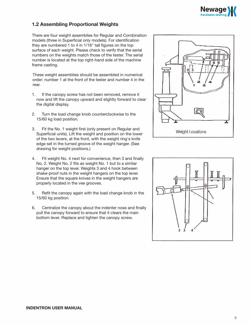
There are four weight assemblies for Regular and Combination models (three in Superficial only models). For identificationthey are numbered 1 to 4 in 1/16" tall figures on the top surface of each weight. Please check to verify that the serial numbers on the weights match those of the tester. The serial number is located at the top right-hand side of the machine frame casting.
These weight assemblies should be assembled in numerical order: number 1 at the front of the tester and number 4 in the rear.
1. If the canopy screw has not been removed, remove it now and lift the canopy upward and slightly forward to clear the digital display.
2. Turn the load change knob counterclockwise to the 15/60 kg load position.
3. Fit the No. 1 weight first (only present on Regular and Super ficial units). Lift the weight and position on the lower of the two levers, at the front, with the weight ring's knife edge set in the turned groove of the weight hanger. (See drawing for weight posi tions.)
4. Fit weight No. 4 next for convenience, then 3 and finally No. 2. Weight No. 2 fits as weight No. 1 but to a similar hanger on the top lever. Weights 3 and 4 hook between shake-proof nuts in the weight hangers on the top lever. Ensure that the square knives in the weight hangers are properly located in the vee grooves.
5. Refit the canopy again with the load change knob in the 15/60 kg position.
6. Centralize the canopy about the indenter nose and finally pull the canopy forward to ensure that it clears the main bottom lever. Replace and tighten the canopy screw.
5

INDENTRON USER MANUAL
SECTION 2: DISPLAY PANEL
The machine is provided with a four digit LED d isplay. It is used to d isplay measured hardness results, to monitor the progress of the test and to display derived statistical data.
The panel has a single toggle switch -see Diagram 1 - the function of which will be described in the following pages.
6

INDENTRON USER MANUAL
SECTION 3: FITTING THE INDENTER
The machine is supplied with both a diamond cone indenter, and a 1/16" ball indenter as standard.
They are held in place with the 4mm socket screw provided. Always ensure that the mounting face of the indenter "nose", and the shoulder of the indenter are clean, and that the 4mm drawscrew is tight.The toggle switch on the front panel must be set to match the indenter being used, i.e. (diamond) or Ø (ball).
7

INDENTRON USER MANUAL
SECTION 4: MAKING A TEST
The pre-load is applied by bringing the specimen into contact with the indenter, by turning the handwheel clockwise.
Movement of the indenter is displayed by a bar graph, and the correct pre-load position is indicated when the horizontal bar touches the end of the fixed bar - See Diagram 2.
When this point is reached, an audible "beep" will be heard, and at this point the hand wheel rotation should be stopped.
The rest of the loading cycle is automatic - application and removal of the additional load - again displayed by the bar graph. At the end of the load cycle, the hardness number will be displayed - resolved to 0.1 units.
SECTION 5: HANDWHEEL OVER-TRAVEL
The pre-load position can be overrun, with the handwheel, by a significant amount without influencing the test. However, if all the over-travel is taken up the bar graph will flash accompanied by an audible beep to indicate no test.
8
INDENTRON USER MANUAL
SECTION 6: CHANGING SCALE
The hardness scale is determined by the combination of the test load and indenter. Scale change is inhibited if the indenter is in contact with a specimen.
SECTION 7: LOAD CHANGE
There are six test loads available:
Rockwell 60, 100 and 150 kgfRockwell Superficial 15, 30 and 45 kgf
The large handlever at the bottom right-hand side of the machine is used to convert the machine from Rockwell to Rockwell Superficial mode. The two positions for the handlever are indicated by the letters R (Rockwell) and S (Superficial Rockwell). This handlever operates a platform which either raises or lowers a set of test weights, and the movement of the handlever should be operated carefully and smoothly.
The small handlever at the top right-hand side of the machine is used to select any of the three test loads in either the Rockwell or superficial Rockwell mode. The two positions for the handlever are indicated by the letters R (Rockwell) and S (Superficial Rockwell). This hand lever operates a platform, which either raises or lowers a set of test weights, and the hand lever should therefore be operated carefully and smoothly.
The small hand lever at the top right hand side of the machine is used to select any of the three test loads in either the Rockwell or Superficial Rockwell mode. The toggle switch on the front panel must be selected to suit the indenter being used, i.e. (diamond) or Ø (ball).
The hardness scale depends upon a combination of test load and indenter type - see table below.
TEST LOAD DIAMOND CONE 1/16" BALL 1/8" BALL 1/4" BALL 1/2" BALL
150 kgf HRC HRG HRK HRP HRV
100 kgf HRD HRB HRE HRM HRS
60 kgf HRA HRF HRH HRL HRR
45 kgf HR45N HR45T HR45W HR45X HR45Y
30 kgf HR30N HR30T HR30W HR30X HR30Y
15 kgf HR15N HR15T HR15W HR15X HR15Y
9
INDENTRON USER MANUAL
SECTION 8: DATA PROCESSING
The software updates a moving average every time the specimen is lowered away from the indenter by the hand-wheel.
The average, range and number oftests from a given sample can be checked at the end of any test, and the facility exists to edit a reading, and to start a new sample.
All these functions are achieved by toggling the switch in the display panel, i.e. from V to 0 or vice versa.
1) To Remove a ReadingWith the readings still displayed on the screen i.e. with the indenter still in contact with the test surface, toggle the switch once.
The reading will now disappear from the screen and is removed from the calculation of mean and range.
2) Sample SizeTo display the number oftests in an on-going sample, toggle the switch once after the specimen has been lowered away from the indenter.
3) MeanTo display the mean, at any time during a series of tests, toggle the switch twice after the specimen has been lowered away from the indenter.
4) RangeTo display the range in a series of tests, toggle the switch three times, after the specimen has been lowered away from the indenter.
5) To Start a New Test Series.Toggle the switch a fomth time, after lowering the specimen away from the indenter.Ifit is desired to carry on with the same sample i.e. not to start a new sample, use the machine normally after 2, 3, or 4. A new test series is also started if a measurement cycle is staited after a change in the indenter selection.
SECTION 9: PRINTING RESULTS
If a printer is connected to the machine the hardness result is printed after each test as the leadscrew is lowered. The mean and range values are appended on the fomth toggle of the switch as a new series of tests is started.
10
INDENTRON USER MANUAL
SECTION 10: ROUTINE MAINTENANCE
The machine has been designed, as far as possible, so that the effect of normal wear and tear does not influence the machines performance. As a result the need for routine maintenance has been kept to an absolute minimum.
The overriding requirement is that the indenters are handled very carefully, and are stored in a safe place when not in use. The Rockwell diamond indenter is the most vulnerable, and a spare Indenter should always be available.
A damaged ball will also give spurious answers, and, if in doubt the ball should be changed.
It is extremely impo1tant that the support anvil is clean, flat, and free from nicks and bruises. This requ irement also applies to the smfaces of the test blocks, especially the under surface - they should be meticulously clean. It is also necessary that production test specimens are a lso properly suppo1ted, to prevent any motion during the load ing cycle.
The main leadscrew should be lubricated periodically by applying just a few drops of light machine oil. Access to the leadscrew can be obtained by first removing the anvil and bellows cover. Slacken the bellows collar at the top of the bellows using a 2.5mm Allen key and then lower the bellows. After lubrication, nm the leadscrew up and down a few times to distribute the oil. DO NOT OVER LUBRICATE. Refit the bellows by the reverse procedure.
SECTION 11: ERROR CODES
During normal operation the machine runs a series of checks to identify possible malfunction. If an error is detected, then the display will flash an error reference number e.g. Err 2 and the machine will give an audible alert. The cause of the error can be determined from the table below. To clear the alert, lower the leadscrew to clear the specimen from the indenter.
Error Problem Possible Cause Corrective action
0 Machine not reset correctly Power fail duringmeasurement cycle
Lower leadscrew, turn poweroff for 5s and then back on
1 Major load not applied Motion failure Consult Newage
2 Overtravel Leadscrew wound uptoo far
Lower specimen clear of indenterand retry
3 Preload Leadscrew lowered slightly after preload level achieved
Lower specimen clear of indenterand retry
4 Out of indenter travel Specimen support too soft Improve specimen support
5 Major load not removed Motion failureMotor/relay/fuse/connection
Consult Newage
6 Negative depth Penetration measurementincorrect
Unblock loading lever-arm
7 Out of calibrated range Compliant specimen supportSpecimen too soft
Improve specimen supportSelect lower test force
11

INDENTRON USER MANUAL
SECTION 12: SERIAL INTERFACE
The serial interface on the NI-500 hardness testing machine provides the ability to print out results on a serial printer, or to communicate data to a PC.
Electrical CharacteristicsSignal levels conform to RS232C Interface Standards with the following signals available:
Pin Designation Description2 TXD out Transmit data3 RXD in Receive data4 DSR in Data set ready5 GND Signal ground6 DTR out Data tenninal ready
The connector on the rear of the machine is a 9 way miniature D socket.
Data rateThe transmission rate is fixed at 1200 baud.
Serial data formatData is transferred in asynchronous format consisting of one statt bit (zero), eight data bits in least significant bit first order, no parity bit, and one stop bit. All information transfer is in ASCII character fonnat (bit 8 set to zero).
Hardware handshake signalsWith power to the machine, Data Terminal Ready is raised and when data is ready to be transferred, the machine will pause for 50ms for Data Set Ready to be returned before commencing transmission. If DSR is lowered during transmission, the current character will be completed and then a timeout of 50ms is commenced for DSR to be restored in order to complete the message.
All data output takes place at the end of a measurement cycle as the leadscrew is lowered to remove the test piece. This procedure gives the user the opportunity to cancel the result while the indenter is still in contact with the test piece.
Note; the normal settings for a connected device would therefore be 1200 baud, 8data bits, no parity, 1 stop bit and hardware flow control.
12
INDENTRON USER MANUAL
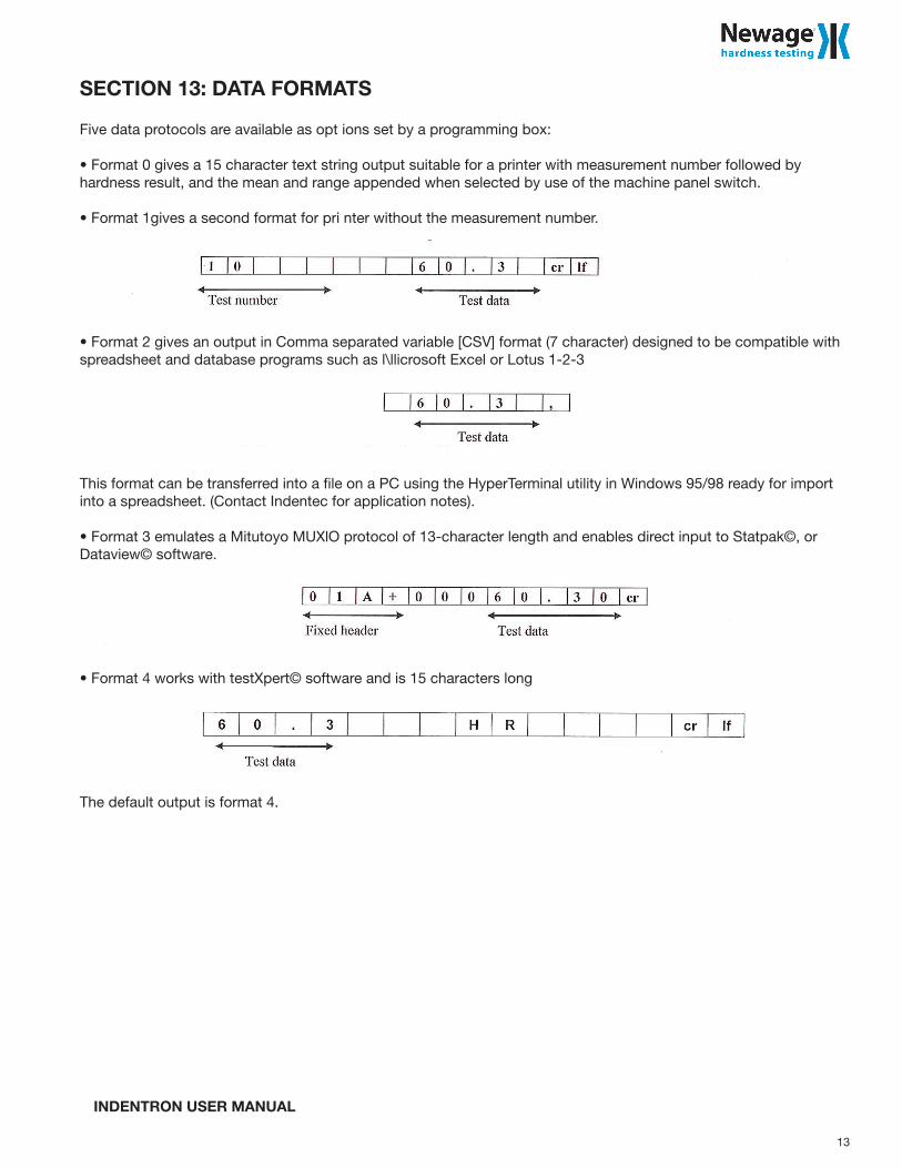
SECTION 13: DATA FORMATS
Five data protocols are available as opt ions set by a programming box:
• Format 0 gives a 15 character text string output suitable for a printer with measurement number followed by hardness result, and the mean and range appended when selected by use of the machine panel switch.
• Format 1gives a second format for pri nter without the measurement number.
• Format 2 gives an output in Comma separated variable [CSV] format (7 character) designed to be compatible with spreadsheet and database programs such as l\llicrosoft Excel or Lotus 1-2-3
This format can be transferred into a file on a PC using the HyperTerminal utility in Windows 95/98 ready for import into a spreadsheet. (Contact Indentec for application notes).
• Format 3 emulates a Mitutoyo MUXlO protocol of 13-character length and enables direct input to Statpak©, or Dataview© software.
• Format 4 works with testXpert© software and is 15 characters long
The default output is format 4.
13

INDENTRON USER MANUAL
SECTION 14: DATAVIEW CONFIGURATION
1. Connect calibration box into RS232 port on hardness tester.2. Press RS232 Language.3. With up/down arrows set hardness tester to OPl . Press Enter to confirm selection.4. Disconnect calibration box.5. Connect hardness tester to pc.6. Open Dataview software. Be sure to connect USB key as it contains software license.7. Select "Comm. Setup". Under mode select "Online".8. Select "Comm. Setup". Select "Communication Settings".9. Communication Setup window will appear.10. Assure Communications Port matches USB p011in Device Manager.11. Set as follows: Baud Rate to 1200. Data size 8. Parity-None. Handshake-XOnXOff. Data Field-0. Select OK.12. Place sample on flat anvil. Take machine to preload stage. Allow machine to complete test.13. Lower sample away from diamond indenter. 14.Hardness value will appear on Dataview software.
14
INDENTRON USER MANUAL
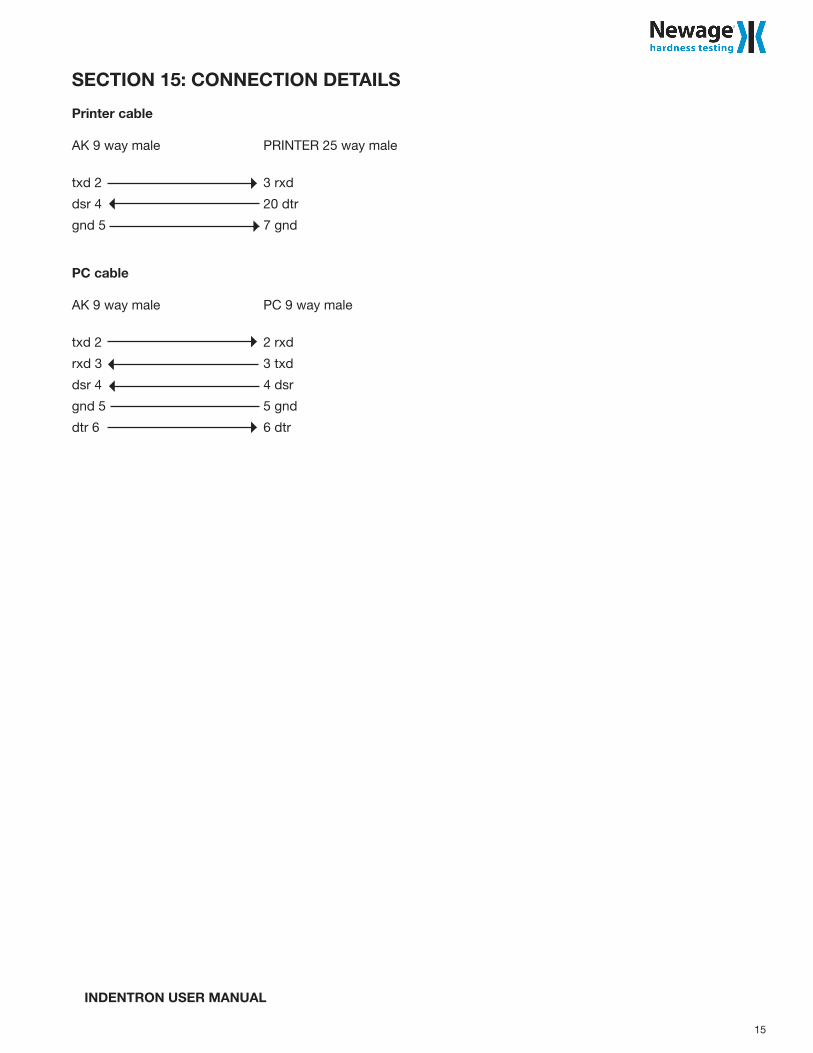
SECTION 15: CONNECTION DETAILS
Printer cable
AK 9 way male PRINTER 25 way male
txd 2 3 rxd
dsr 4 20 dtr
gnd 5 7 gnd
PC cable
AK 9 way male PC 9 way male
txd 2 2 rxd
rxd 3 3 txd
dsr 4 4 dsr
gnd 5 5 gnd
dtr 6 6 dtr
15

820 Pennsylvania Blvd., Feasterville PA 19053 USATel: 215-355-6900 • Fax: 215-354-1803
[email protected] • www.hardnesstesters.com
Newagehardness testing
Pub code: P/N MA-226REV. 00