Increase in fatigue life of spur gear by introducing circular stress relieving feature
10
82 INCREASE IN FATIGUE LIFE OF SPUR GEAR BY INTRODUCING CIRCULAR STRESS RELIEVING FEATURE Mr. Anand Kalani 1 , Mrs. Rita Jani 2 1 Mechanical Engineering Department, Government Engineering College Palanpur, India 2 Mechanical Engineering Department, Shantilal Shah Engineering College, Bhavnagar, India ABSTRACT Increment of fatigue life of spur gear is the main target of this research. This work presents the possibilities of using the stress redistribution techniques by introducing the circular stress relieving features in the stressed zone to the advantage of reduction of root fillet stress in spur gear. The pinion spur gear is taken under examination and the parameter for comparison is principal stress measured by applying load on HPSTC [Highest Point of Single Tooth Contact]. A circular stress relieving feature is introduced on various locations and by doing so a considerable amount of reduction in principle stress was examined which resulted in long operating life of spur gear. Key words: Bending Stress, HPSTC, Spur Gear, Stress Relieving Feature, Stress Distribution. 1. INTRODUCTION Spur gears play most important role in transmission system from ancient time to today’s high end technology world. Fatigue is a possible failure mode for a spur gear. It usually happens unexpectedly and can be very expensive in terms of both replacement costs and down time. Much effort has been put forth in the scientific and engineering communities to understand fatigue and design against it so from time to time, changes where done in the design and material to increase the fatigue life of spur gears by different researchers. The objective of this research is to reduce the root fillet stress of spur gear by introducing the stress relief features on a stressed gear [1] . Therefore a systematic study is carried out to investigate the effect of introducing circular stress relief feature at different locations. Further to find out the more beneficial location and parameter of the stress relieving feature on a stressed gear tooth. This study hypothesized that systematic experimentation with stress reliving feature of different dimension, combination and location would provide a fundamental understanding of their effects on stress in spur gears. This work finds its application for where high load operating condition prevails along with requirement of high operating life of spur gears. INTERNATIONAL JOURNAL OF MECHANICAL ENGINEERING AND TECHNOLOGY (IJMET) ISSN 0976 – 6340 (Print) ISSN 0976 – 6359 (Online) Volume 6, Issue 5, May (2015), pp. 82-91 © IAEME: www.iaeme.com/IJMET.asp Journal Impact Factor (2015): 8.8293 (Calculated by GISI) www.jifactor.com IJMET © I A E M E
-
Upload
iaeme-publication -
Category
Engineering
-
view
108 -
download
1
Transcript of Increase in fatigue life of spur gear by introducing circular stress relieving feature
International Journal of Mechanical Engineering and Technology (IJMET), ISSN 0976 – 6340(Print),
ISSN 0976 – 6359(Online), Volume 6, Issue 5, May (2015), pp. 82-91© IAEME
82
INCREASE IN FATIGUE LIFE OF SPUR GEAR BY
INTRODUCING CIRCULAR STRESS RELIEVING
FEATURE
Mr. Anand Kalani1, Mrs. Rita Jani
2
1Mechanical Engineering Department, Government Engineering College Palanpur, India
2Mechanical Engineering Department, Shantilal Shah Engineering College, Bhavnagar, India
ABSTRACT
Increment of fatigue life of spur gear is the main target of this research. This work presents
the possibilities of using the stress redistribution techniques by introducing the circular stress
relieving features in the stressed zone to the advantage of reduction of root fillet stress in spur gear.
The pinion spur gear is taken under examination and the parameter for comparison is principal stress
measured by applying load on HPSTC [Highest Point of Single Tooth Contact]. A circular stress
relieving feature is introduced on various locations and by doing so a considerable amount of
reduction in principle stress was examined which resulted in long operating life of spur gear.
Key words: Bending Stress, HPSTC, Spur Gear, Stress Relieving Feature, Stress Distribution.
1. INTRODUCTION
Spur gears play most important role in transmission system from ancient time to today’s high
end technology world. Fatigue is a possible failure mode for a spur gear. It usually happens
unexpectedly and can be very expensive in terms of both replacement costs and down time. Much
effort has been put forth in the scientific and engineering communities to understand fatigue and
design against it so from time to time, changes where done in the design and material to increase the
fatigue life of spur gears by different researchers.
The objective of this research is to reduce the root fillet stress of spur gear by introducing
the stress relief features on a stressed gear [1]
. Therefore a systematic study is carried out to
investigate the effect of introducing circular stress relief feature at different locations. Further to
find out the more beneficial location and parameter of the stress relieving feature on a stressed gear
tooth. This study hypothesized that systematic experimentation with stress reliving feature of
different dimension, combination and location would provide a fundamental understanding of their
effects on stress in spur gears. This work finds its application for where high load operating condition
prevails along with requirement of high operating life of spur gears.
INTERNATIONAL JOURNAL OF MECHANICAL ENGINEERING AND
TECHNOLOGY (IJMET)
ISSN 0976 – 6340 (Print)
ISSN 0976 – 6359 (Online)
Volume 6, Issue 5, May (2015), pp. 82-91
© IAEME: www.iaeme.com/IJMET.asp
Journal Impact Factor (2015): 8.8293 (Calculated by GISI)
www.jifactor.com
IJMET
© I A E M E
International Journal of Mechanical Engineering and Technology (IJMET), ISSN 0976 – 6340(Print),
ISSN 0976 – 6359(Online), Volume 6, Issue 5, May (2015), pp. 82-91© IAEME
83
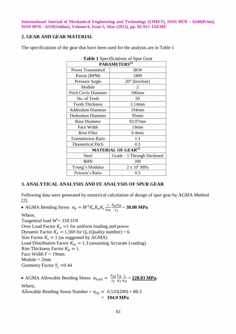
2. GEAR AND GEAR MATERIAL
The specifications of the gear that have been used for the analysis are in Table 1
Table 1 Specifications of Spur Gear
PARAMETERS[1]
Power Transmitted 3KW
Pinion (RPM) 1800
Pressure Angle 20° [Involute]
Module 2
Pitch Circle Diameter 100mm
No. of Teeth 50
Tooth Thickness 3.14mm
Addendum Diameter 104mm
Dedendum Diameter 95mm
Base Diameter 93.97mm
Face Width 19mm
Root Fillet 0.4mm
Transmission Ratio 1:1
Diametrical Pitch 0.5
MATERIAL OF GEAR[1]
Steel Grade – 1 Through Hardened
BHN 200
Young’s Modulus 2 x 10⁵ MPa
Poisson’s Ratio 0.3
3. ANALYTICAL ANALYSIS AND FE ANALYSIS OF SPUR GEAR
Following data were generated by numerical calculation of design of spur gear by AGMA Method
[2].
AGMA Bending Stress
= 38.08 MPa
Where,
Tangential load Wt= 318.31N
Over Load Factor 1 for uniform loading and power
Dynamic Factor 1.569 for Qv (Quality number) = 6
Size Factor 1 (as suggested by AGMA)
Load Distribution Factor 1.3 (assuming Accurate Loading)
Rim Thickness Factor 1.
Face Width F = 19mm.
Module = 2mm
Geometry Factor 0.44
AGMA Allowable Bending Stress
= 228.03 MPa.
Where,
Allowable Bending Stress Number = 0.533(200) + 88.3
= 194.9 MPa

International Journal of Mechanical Engineering and Technology (IJMET), ISSN 0976 – 6340(Print),
ISSN 0976 – 6359(Online), Volume 6, Issue 5, May (2015), pp. 82-91© IAEME
84
Considering Pinion life of 106 cycles and BHN = 200,
we have YN = 4.9404 (N)-0.1045
Where, N = 106 cycles; Stress Cycle Factor YN = 1.17; Temperature Factor KT = 1 (working
Temperature < 120⁰); Reliability Factor KR = 1.00 (for reliability = 0.99); Safety Factor =
1(assuming)
HPSTC (HIGHEST POINT OF SINGLE POINT CONTACT)
[3]
Diameter of load application point for Pinion (HPSTC) =
= 51.53mm
Where,
= Radius of Highest Point of Contact
= Outside Radius of Pinion = 52mm
= Base Diameter of Pinion = 46.985mm
= Base Pitch = Dia. Pitch x cos= 1.47mm
mp = Contact Ratio = 1.758
The three teeth of spur gear are developed with that help of CAD Software SOLID EGDE – ST3 as
shown in Figure-1
Finite element Solution
The finite element analysis is done by applying the element, constraint and load. The stress
distribution after the solution is as shown in Figure-2.
The analysis shows that the root fillet stress generated is 210.867 MPa which is valid for
further analysis as it is less than the numerically calculated value i.e. 228.03 MPa.

International Journal of Mechanical Engineering and Technology (IJMET), ISSN 0976 – 6340(Print),
ISSN 0976 – 6359(Online), Volume 6, Issue 5, May (2015), pp. 82-91© IAEME
85
4. FINITE ELEMENT ANALYSIS BY INTRODUCING CIRCULAR STRESS RELIEVING
FEATURE
Six (06) different locations where taken under study around the tooth profile of spur gear.
The study is done by varying the location of hole along three regions, a. parallel to dedendum, b.
along root fillet, and c. along involute profile. The locations are named as curve – 1 to curve – 6 as
shown in Figure – 3, 5, 7, 9, 11 and 13 respectively.
The hole diameter of 0.2mm and 0.5mm offset distance from the edge of curve is taken and
kept fixed for all positions.
Curve – 1 & curve – 6 has right end as start point and left end as end point. Curve – 2,3,4,5
has bottom point as start point and upper point as end point.
The curve is divided into ten parts and the hole is placed parametrically according to the
curve dimension.
The sensitivity analysis of each curve by introducing the circular hole stress relieving feature
is represented graphically in Figure-4,6,8,10,12 and 14 respectively for Curve – 1 to Curve – 6.
Figure – 3 Curve-1
Figure – 4 Sensitivity Graph-1
Figure – 5 Curve-2
Figure – 6 Sensitivity Graph-2
Figure – 7 Curve-3
Figure – 8 Sensitivity Graph-3

International Journal of Mechanical Engineering and Technology (IJMET), ISSN 0976 – 6340(Print),
ISSN 0976 – 6359(Online), Volume 6, Issue 5, May (2015), pp. 82-91© IAEME
86
Figure – 9 Curve-4
Figure – 10 Sensitivity Graph-4
Figure – 11 Curve-5
Figure – 12 Sensitivity Graph-5
Figure – 13 Curve-6
Figure – 14 Sensitivity Graph-6
5. FINITE ELEMENT ANALYSIS BY KEEPING HOLE DIAMETER CONSTANT AND
OFFSET DISTANCE VARIABLE.
The positions at which minimum root fillet stress generated is taken into account for further
study. On this positions on curve -1 and curve-3; the hole diameter is kept fix 0.2mm where
minimum root fillet stress is obtained and the offset distance from the edge of the curve is varied by
an increment of 0.1mm up to 1.0mm as shown in Figure-15 and 17 resp.
Figure – 15 Curve-1
Figure – 16 Sensitivity Graph-1
International Journal of Mechanical Engineering and Technology (IJMET), ISSN 0976 – 6340(Print),
ISSN 0976 – 6359(Online), Volume 6, Issue 5, May (2015), pp. 82-91© IAEME
87
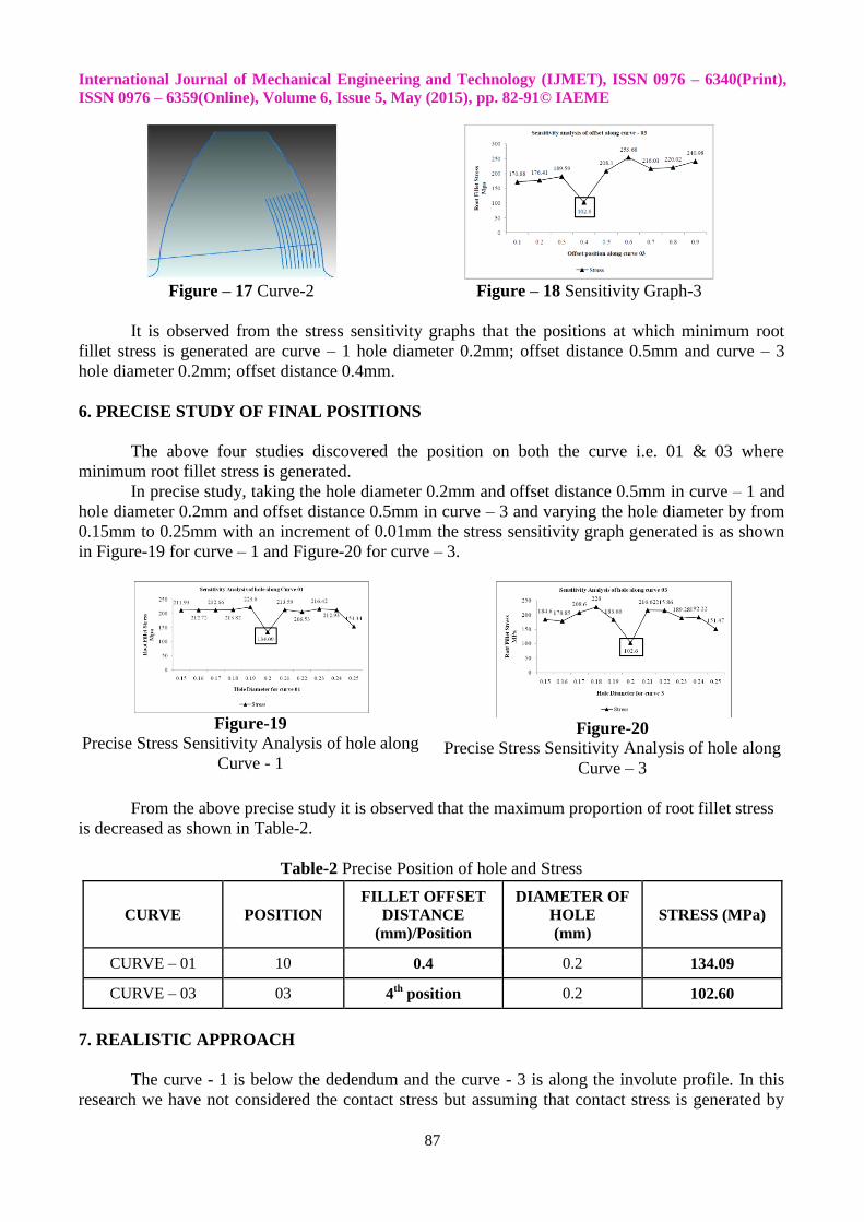
Figure – 17 Curve-2
Figure – 18 Sensitivity Graph-3
It is observed from the stress sensitivity graphs that the positions at which minimum root
fillet stress is generated are curve – 1 hole diameter 0.2mm; offset distance 0.5mm and curve – 3
hole diameter 0.2mm; offset distance 0.4mm.
6. PRECISE STUDY OF FINAL POSITIONS
The above four studies discovered the position on both the curve i.e. 01 & 03 where
minimum root fillet stress is generated.
In precise study, taking the hole diameter 0.2mm and offset distance 0.5mm in curve – 1 and
hole diameter 0.2mm and offset distance 0.5mm in curve – 3 and varying the hole diameter by from
0.15mm to 0.25mm with an increment of 0.01mm the stress sensitivity graph generated is as shown
in Figure-19 for curve – 1 and Figure-20 for curve – 3.
Figure-19
Precise Stress Sensitivity Analysis of hole along
Curve - 1
Figure-20
Precise Stress Sensitivity Analysis of hole along
Curve – 3
From the above precise study it is observed that the maximum proportion of root fillet stress
is decreased as shown in Table-2.
Table-2 Precise Position of hole and Stress
7. REALISTIC APPROACH
The curve - 1 is below the dedendum and the curve - 3 is along the involute profile. In this
research we have not considered the contact stress but assuming that contact stress is generated by
CURVE POSITION
FILLET OFFSET
DISTANCE
(mm)/Position
DIAMETER OF
HOLE
(mm)
STRESS (MPa)
CURVE – 01 10 0.4 0.2 134.09
CURVE – 03 03 4th
position 0.2 102.60

International Journal of Mechanical Engineering and Technology (IJMET), ISSN 0976 – 6340(Print),
ISSN 0976 – 6359(Online), Volume 6, Issue 5, May (2015), pp. 82-91© IAEME
88
mating of gear teeth hole on curve – 3 may decrease the strength of gear tooth. The hole on the curve
– 1 which is below the dedendum will not be affected by the contact stress and it eases the
manufacturing of gear. So, for further study the hole on the curve – 1 is considered.
This study is done by introducing the hole position of curve – 1 where minimum root fillet
stress is generated on both side of gear tooth i.e. on left hand (curve -6) and right hand side (curve -
1) of tooth maintaining the symmetry as shown in Figure-21 and the stress sensitivity graphs so
generated is shown in Figure-22.
The combination study is done by keeping the hole position on curve -1 fix and hole position
on curve - 6 varying along the curve.
Figure-21 Symmetric Hole Position
Figure- 22 Stress Sensitivity Analysis of Holes
on Curve – 1 and Curve - 2
By combination of hole on both curve – 01 and curve - 06 the minimum stress generated is
138.64 MPa at position as shown in Table – 3.
Table-3 Symmetric Position of Hole and Stress
By introducing the holes in gear there will be combined effect and for ease of making hole
and manufacturing gear both the position of hole i.e on curve -1 and curve -6 are taken into
consideration and by this way two hole of diameter 0.2mm on either side of gear tooth is introduced
as shown in Figure-23.
The final arrangement of the holes on gear is than analyzed by Finite Element Method in
ANSYS -11 and the root fillet stressed is measured. As shown in Figure-24.
Figure-23 Final Combination of holes on Curve – 1 and Curve – 6
CURVE POSITION FILLET OFFSET
DISTANCE (mm)
DIAMETER OF
HOLE (mm)
STRESS
(MPa)
CURVE – 01 10 0.4 0.2 138.64 MPa
CURVE – 06 02 0.4 0.2

International Journal of Mechanical Engineering and Technology (IJMET), ISSN 0976 – 6340(Print),
ISSN 0976 – 6359(Online), Volume 6, Issue 5, May (2015), pp. 82-91© IAEME
89
Figure-24 Finite Element Analysis of Gear Tooth having Final Position of Holes
Fatigue failure of gear tooth is normally due to Tensile Stress at the Root Fillet, the Root
Stress on the compressive side does not take part in fatigue failure. In this case the Stress on the
Tensile Side is considered.
The spur gear with stress relieving feature will look as shown in Figure-24. The comparative
study of both the condition i.e. root fillet stress generated without stress relieving feature and with
stress relieving feature is as shown in Table-4.
Figure-25 Spur Gear with Final Arrangement of Holes
Table - 4 Comparison of Root Fillet Stress
The outcome of final study results in reduction of Root Fillet Stress from 210.867 MPa to 158.170
MPa. i.e up to 23% of reduction.
8 COMPARISON OF WORKING HOUR LIFE [4]
8.1 Spur Gear with-Out Stress Relieving Feature
The working hour life of spur gear with-out stress relieving feature is
Spur Gear Root Fillet Stress
MPa
Stress
Reduction
MPa
Percentage
Reduction in
Stress
Without Stress Relieving feature 210.867 52.697 23%
With Stress Relieving feature 158.170
International Journal of Mechanical Engineering and Technology (IJMET), ISSN 0976 – 6340(Print),
ISSN 0976 – 6359(Online), Volume 6, Issue 5, May (2015), pp. 82-91© IAEME
90
Where,
= Working Hours of Gear; = Load Cycle = 10
6;
= No. of revolution per minute of pinion = 1800 rpm
= no. of load application by one turn of gear = 1 (only single tooth contact)
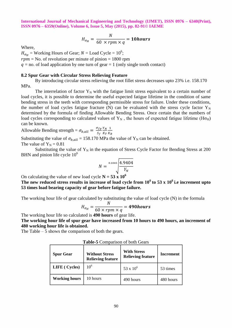
8.2 Spur Gear with Circular Stress Relieving Feature
By introducing circular stress relieving the root fillet stress decreases upto 23% i.e. 158.170
MPa.
The interrelation of factor YN with the fatigue limit stress equivalent to a certain number of
load cycles, it is possible to determine the useful expected fatigue lifetime in the condition of same
bending stress in the teeth with corresponding permissible stress for failure. Under these conditions,
the number of load cycles fatigue fracture (N) can be evaluated with the stress cycle factor YN
determined by the formula of finding Allowable Bending Stress. Once certain that the numbers of
load cycles corresponding to calculated values of YN , the hours of expected fatigue lifetime (HσH)
can be known.
Allowable Bending strength =
Substituting the value of = 158.170 MPa the value of YN can be obtained.
The value of YN = 0.81
Substituting the value of YN in the equation of Stress Cycle Factor for Bending Stress at 200
BHN and pinion life cycle 106
On calculating the value of new load cycle N = 53 x 106
The new reduced stress results in increase of load cycle from 106
to 53 x 106
i.e increment upto
53 times load bearing capacity of gear before fatigue failure.
The working hour life of gear calculated by substituting the value of load cycle (N) in the formula
The working hour life so calculated is 490 hours of gear life.
The working hour life of spur gear have increased from 10 hours to 490 hours, an increment of
480 working hour life is obtained.
The Table – 5 shows the comparison of both the gears.
Table-5 Comparison of both Gears
Spur Gear
Without Stress
Relieving feature
With Stress
Relieving feature Increment
LIFE ( Cycles) 106 53 x 10
6 53 times
Working hours 10 hours 490 hours 480 hours
International Journal of Mechanical Engineering and Technology (IJMET), ISSN 0976 – 6340(Print),
ISSN 0976 – 6359(Online), Volume 6, Issue 5, May (2015), pp. 82-91© IAEME
91
9. CONCLUSION
The maximum load on the pinion is at highest point of Single Tooth Contact (HPSTC). The
most critical design is for a gear ratio of 1:1.
By introducing the circular stress relieving feature below dedendum the stress analysis shows
the root fillet have lesser tensile stress than the trailing root fillet which have greater compressive
stress.
It is concluded from the stress analysis that the hole at involute profile will introduce more
stress than the hole under the dedendum which leads to increase in tooth life and so the life of whole
gear.
The choice of the size and location of the hole is not a simple process, due to the nonlinear
variations in a complex geometry, as the studies have shown.
The introduction of a hole on the dedendum circle reduces the stress levels by a very high
percentage with a small loss of rigidity of the tooth.
This translates into an exponential increase in the life of the gear due to a better location on the
S-N curve for fatigue loading.
10. SCOPE OF FUTURE WORK
Other types of gears like helical, bevel, worm etc. can also be studied.
Different shapes of hole can also be studied for relieving stress.
Other failure criteria can be used for the study other than fatigue.
The study can be done using experimental verification of stress relief by prototype / actual
testing.
REFERENCES
1. Fredette L. and Brown M., “Gear Stress Reduction Using Internal Stress Relief Features”,
Journal of Mechanical Design, 1997, vol. 11, pp. 518-521.
2. Andrzej Kawalec, Jerzy Wiktor and Dariusz Ceglarek, “Comparative Analysis of Tooth-Root
Strength Using ISO and AGMA Standards in Spur and Helical Gears With FEM-based
Verification”, Journal of Mechanical Design Copyright, September 2006, Vol. 128, 1141.
3. Alireza Dastan, “The Study Of The Backlash Effects On Geometry Factor of Spur Gears by the
Finite Element Method by Using ANSYS”, Proceedings of the International Conference on
Mechanical Engineering, Dhaka, Bangladesh, 29- 31, December 2007.
4. G. Gonzalez Rey, R. J. Garcia Martin, and P. Frechilla Fernandez, “Estimating Gear Fatigue
Life”, Gear Solutions, October 2007.
5. http://www.gearsolutions.com/media//uploads/assets/PDF/Articles/Gonzalez1007.pdf
6. Budynas−Nisbett, Shigley’s Mechanical Engineering Design, Eighth Edition, Tata McGraw Hill
Publishing Company, 2006.
7. Gitin M. Maitra, Handbook of Gear Design, Second Edition, Tata McGraw-Hill Publishing
Company, 2001.
8. Kohara Gear Company of Japan and Dr. George Michalec, Hand book of metric drive
components, catalog 785.
9. Faydor L. Litvin, Development of Gear Technology and Theory of Gearing, NASA Reference
Publication, Lewis Research Center Cleveland, Ohio.
10. Documentation of ANSYS – Release 11.
11. Anand Kalani, Sandeep Soni and Rita Jani, “Expert Knowledge-Base System For Computer
Aided Design of Full Hydrodynamic Journal Bearing”, International Journal of Mechanical
Engineering & Technology (IJMET), Volume 6, Issue 8, 2015, pp. 46 - 58, ISSN Print: 0976 –
6340, ISSN Online: 0976 – 6359.