Improved Radiation Efficiency of Mobile Systems and ... · PDF fileImproved Radiation...
6
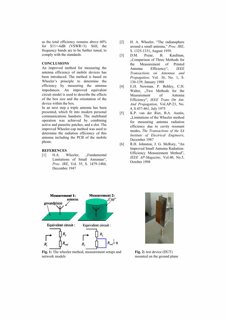
Improved Radiation Efficiency of Mobile Systems and application to a Novel Multiband Antenna D. Heberling, M. Geissler, O. Litschke, Marta Martínez-Vázquez IMST GmbH Carl-Friedrich-Gauß-Straße 2, D-47475 Kamp-Lintfort, Germany [email protected] ABSTRACT In this paper an improved method for measuring the radiation efficiency of small devices is introduced. The method is based on Wheeler’s principle of measuring the antenna impedance within two controlled environments: free space and a closed metallic box. An extended equivalent circuit is introduced, that gives an exact description of the behavior of the small device within the metallic box. This model is the basis for the determination of the radiation efficiency, independent of the size of the box and the location of the device within the box. In the next part of the paper, a concept for an integrated up-to-date multiband antenna for a GSM mobile phone is presented. The characterization of the radiation efficiency by the above mentioned method proves the new way to characterize the efficiency. WHEELER’S METHOD The radiation efficiency rad η describes the losses within the antenna structure. It is defined by the ratio of the radiated power P rad over the power P in going into the antenna terminal [1]: rad rad in P P η = (1) The total efficiency tot η includes also the return losses. It can be calculated from the radiation efficiency with respect to the reflection coefficient S 11 : ( ) 11 1 ² tot rad S η η = − (2) Wheeler introduced a method for determining the radiation efficiency of antennas by performing two measurements, the first one in free space and the second one within a closed sphere [2] (Fig. 1). He assumes, that the antenna at resonance frequency can be modelled as two series resistances; the radiation resistance R rad and the loss resistance R L . The first measurement delivers the sum of both contributions R 1 , the second measurement delivers R 2 , which corresponds to R L . The radiation efficiency can be calculated as [4]: 1 2 1 rad rad L rad R R R R R R η − = = + (3) Several investigations show, that one can obtain good results for electrically small antennas. However, all these investigations focus on antennas directly mounted on the ground plane, e.g. loop antennas or patch antennas [3][4]. Moreover, this approach is only valid as long as the inner losses of the antenna can be interpreted as a series resistance [3]. APPLICATION FOR SMALL DEVICES Antennas of small mobile devices however do not use large ground planes. They are typically mounted on the top side or the back side of the mobile device, and the device acts as an active counter pole of the antenna. Therefore, the whole device has to be considered in order to determine the radiation efficiency correctly. Two samples of antennas mounted on small devices are built and measured using Wheeler’s method. The first sample is an 1800 MHz PIFA on a 100x40mm² PCB, the second sample is an 1800 MHz patch also on a 100x40 mm 2 PCB (Fig. 2). Losses are introduced by implementing a 10 Ohms resistance into the feeding pin of these antennas. Measurement 1 is performed by installing the device within
-
Upload
duongduong -
Category
Documents
-
view
215 -
download
0
Transcript of Improved Radiation Efficiency of Mobile Systems and ... · PDF fileImproved Radiation...

Improved Radiation Efficiency of Mobile Systems and application to a
Novel Multiband Antenna
D. Heberling, M. Geissler, O. Litschke, Marta Martínez-Vázquez
IMST GmbH Carl-Friedrich-Gauß-Straße 2, D-47475 Kamp-Lintfort, Germany
ABSTRACT In this paper an improved method for measuring the radiation efficiency of small devices is introduced. The method is based on Wheeler’s principle of measuring the antenna impedance within two controlled environments: free space and a closed metallic box. An extended equivalent circuit is introduced, that gives an exact description of the behavior of the small device within the metallic box. This model is the basis for the determination of the radiation efficiency, independent of the size of the box and the location of the device within the box. In the next part of the paper, a concept for an integrated up-to-date multiband antenna for a GSM mobile phone is presented. The characterization of the radiation efficiency by the above mentioned method proves the new way to characterize the efficiency. WHEELER’S METHOD The radiation efficiency radη describes the losses within the antenna structure. It is defined by the ratio of the radiated power Prad over the power Pin going into the antenna terminal [1]:
radrad
in
PP
η = (1)
The total efficiency totη includes also the return losses. It can be calculated from the radiation efficiency with respect to the reflection coefficient S11:
( )111 ²tot radSη η= − (2)
Wheeler introduced a method for determining the radiation efficiency of antennas by performing two measurements, the first one in free space and the second
one within a closed sphere [2] (Fig. 1). He assumes, that the antenna at resonance frequency can be modelled as two series resistances; the radiation resistance Rrad and the loss resistance RL. The first measurement delivers the sum of both contributions R1, the second measurement delivers R2, which corresponds to RL. The radiation efficiency can be calculated as [4]:
1 2
1
radrad
L rad
R R RR R R
η −= =+
(3)
Several investigations show, that one can obtain good results for electrically small antennas. However, all these investigations focus on antennas directly mounted on the ground plane, e.g. loop antennas or patch antennas [3][4]. Moreover, this approach is only valid as long as the inner losses of the antenna can be interpreted as a series resistance [3]. APPLICATION FOR SMALL DEVICES Antennas of small mobile devices however do not use large ground planes. They are typically mounted on the top side or the back side of the mobile device, and the device acts as an active counter pole of the antenna. Therefore, the whole device has to be considered in order to determine the radiation efficiency correctly. Two samples of antennas mounted on small devices are built and measured using Wheeler’s method. The first sample is an 1800 MHz PIFA on a 100x40mm² PCB, the second sample is an 1800 MHz patch also on a 100x40 mm2 PCB (Fig. 2). Losses are introduced by implementing a 10 Ohms resistance into the feeding pin of these antennas. Measurement 1 is performed by installing the device within
an absorbing box. For measurement 2 the device is placed inside the metallic box, using a coaxial through connection. The efficiency is calculated using (3), considering only the real parts of the measured impedances:
1 2
1
Re{ }Re{ } Re{ }
Re{ } Re{ } Re{ }
radrad
V rad
ZZ Z
Z ZZ
η =+
−=
(4)
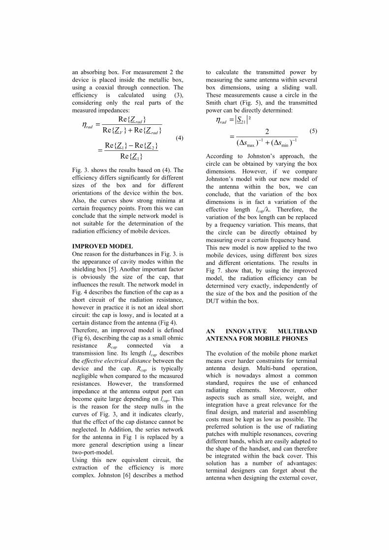
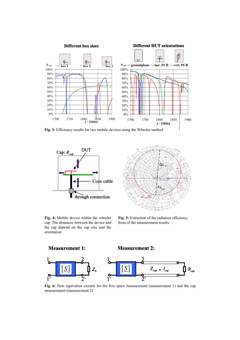
Fig. 3. shows the results based on (4). The efficiency differs significantly for different sizes of the box and for different orientations of the device within the box. Also, the curves show strong minima at certain frequency points. From this we can conclude that the simple network model is not suitable for the determination of the radiation efficiency of mobile devices. IMPROVED MODEL One reason for the disturbances in Fig. 3. is the appearance of cavity modes within the shielding box [5]. Another important factor is obviously the size of the cap, that influences the result. The network model in Fig. 4 describes the function of the cap as a short circuit of the radiation resistance, however in practice it is not an ideal short circuit: the cap is lossy, and is located at a certain distance from the antenna (Fig 4). Therefore, an improved model is defined (Fig 6), describing the cap as a small ohmic resistance Rcap connected via a transmission line. Its length lcap describes the effective electrical distance between the device and the cap. Rcap is typically negligible when compared to the measured resistances. However, the transformed impedance at the antenna output port can become quite large depending on lcap. This is the reason for the steep nulls in the curves of Fig. 3, and it indicates clearly, that the effect of the cap distance cannot be neglected. In Addition, the series network for the antenna in Fig 1 is replaced by a more general description using a linear two-port-model. Using this new equivalent circuit, the extraction of the efficiency is more complex. Johnston [6] describes a method
to calculate the transmitted power by measuring the same antenna within several box dimensions, using a sliding wall. These measurements cause a circle in the Smith chart (Fig. 5), and the transmitted power can be directly determined:
21
1 1max min
²2
( ) ( )
rad S
s s
η
− −
=
=∆ + ∆
(5)
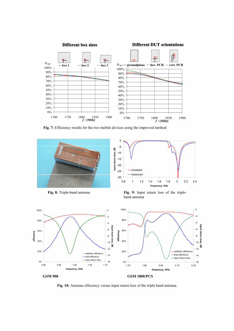
According to Johnston’s approach, the circle can be obtained by varying the box dimensions. However, if we compare Johnston’s model with our new model of the antenna within the box, we can conclude, that the variation of the box dimensions is in fact a variation of the effective length lcap/λ. Therefore, the variation of the box length can be replaced by a frequency variation. This means, that the circle can be directly obtained by measuring over a certain frequency band. This new model is now applied to the two mobile devices, using different box sizes and different orientations. The results in Fig 7. show that, by using the improved model, the radiation efficiency can be determined very exactly, independently of the size of the box and the position of the DUT within the box.
AN INNOVATIVE MULTIBAND ANTENNA FOR MOBILE PHONES
The evolution of the mobile phone market means ever harder constraints for terminal antenna design. Multi-band operation, which is nowadays almost a common standard, requires the use of enhanced radiating elements. Moreover, other aspects such as small size, weight, and integration have a great relevance for the final design, and material and assembling costs must be kept as low as possible. The preferred solution is the use of radiating patches with multiple resonances, covering different bands, which are easily adapted to the shape of the handset, and can therefore be integrated within the back cover. This solution has a number of advantages: terminal designers can forget about the antenna when designing the external cover,
the phone becomes more robust as there are no external radiating elements that could break of, and the antennas can be produced in a more cost-effective way. On the other hand, the antennas must operate in two or more frequency bands, but still be confined within a volume that becomes ever smaller. Therefore, the main goal of the antenna designer is nowadays how to achieve the miniaturisation of the radiating structure without loss of efficiency. DESIGN CONSIDERATIONS Printed antennas are nowadays an interesting alternative for mobile terminals, as current requirements are focussing on minimisation of the size and weight of the handsets. Moreover, the development of new standards and the user’s mobility requirements make it necessary to extend the operation of a handset to cover two or more standards. Thus, it may be necessary to develop terminal antennas that implement different combinations of frequency bands. In many cases, one single feed point is required. Therefore, different resonant modes must be excited, each of them tuned to fit the centre frequency of the band of interest. Unfortunately, some of these bands overlap, like the GSM 1800 and PCS bands. In this paper, a triple band antenna for mobile handsets is presented. To keep a realistic configuration, the antenna was developed within the limits of a 16mm x 36mm rectangular area, with a height of 8 mm over a 36 mm x 95 mm ground plane of FR-4 material. To assure the mechanical stability of the structure, the antenna was attached to an 8 mm-thick foam block without any significant change in its performance. There are two possible alternatives to cover two standards with overlapping bands: to excite a single mode with a sufficient bandwidth, or two mutually coupled modes. If the latter strategy is chosen, it is essential to be able to perfectly control the coupling mechanism, since any modification in the geometry of the patch can result in an important loss of bandwidth. The main concern is then how to tune one of the bands without interfering with the performance of the others. Indeed, to implement these integrated multiband antennas, it is common to use structures
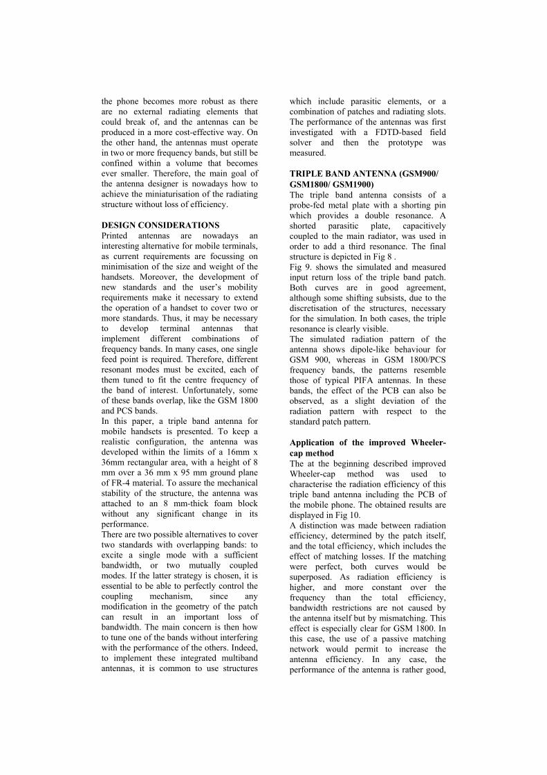
which include parasitic elements, or a combination of patches and radiating slots. The performance of the antennas was first investigated with a FDTD-based field solver and then the prototype was measured. TRIPLE BAND ANTENNA (GSM900/ GSM1800/ GSM1900) The triple band antenna consists of a probe-fed metal plate with a shorting pin which provides a double resonance. A shorted parasitic plate, capacitively coupled to the main radiator, was used in order to add a third resonance. The final structure is depicted in Fig 8 . Fig 9. shows the simulated and measured input return loss of the triple band patch. Both curves are in good agreement, although some shifting subsists, due to the discretisation of the structures, necessary for the simulation. In both cases, the triple resonance is clearly visible. The simulated radiation pattern of the antenna shows dipole-like behaviour for GSM 900, whereas in GSM 1800/PCS frequency bands, the patterns resemble those of typical PIFA antennas. In these bands, the effect of the PCB can also be observed, as a slight deviation of the radiation pattern with respect to the standard patch pattern. Application of the improved Wheeler-cap method The at the beginning described improved Wheeler-cap method was used to characterise the radiation efficiency of this triple band antenna including the PCB of the mobile phone. The obtained results are displayed in Fig 10. A distinction was made between radiation efficiency, determined by the patch itself, and the total efficiency, which includes the effect of matching losses. If the matching were perfect, both curves would be superposed. As radiation efficiency is higher, and more constant over the frequency than the total efficiency, bandwidth restrictions are not caused by the antenna itself but by mismatching. This effect is especially clear for GSM 1800. In this case, the use of a passive matching network would permit to increase the antenna efficiency. In any case, the performance of the antenna is rather good,
as the total efficiency remains above 60% for S11<-6dB (VSWR<3). Still, the frequency bands are to be further tuned, to comply with the standards. CONCLUSIONS An improved method for measuring the antenna efficiency of mobile devices has been introduced. The method is based on Wheeler’s principle to determine the efficiency by measuring the antenna impedances. An improved equivalent circuit model is used to describe the effects of the box size and the orientation of the device within the box. In an next step a triple antenna has been presented, which fit into modern personal communications handsets. The multiband operation was achieved by combining active and parasitic patches, and a slot. The improved Wheeler-cap method was used to determine the radiation efficiency of this antenna including the PCB of the mobile phone. REFERENCES [1] H.A. Wheeler, „Fundamental
Limitations of Small Antennas“, Proc. IRE, Vol. 35, S. 1479-1484, December 1947
[2] H. A. Wheeler, “The radiansphere around a small antenna,” Proc. IRE, S. 1325-1331, August 1959.
[3] D.M. Pozar, B. Kaufman, „Comparison of Three Methods for the Measurement of Printed Antenna Efficiency“, IEEE Transactions on Antennas and Propagation, Vol. 36, No. 1, S. 136-139, January 1988
[4] E.H. Newman, P. Bohley, C.H. Walter, „Two Methods for the Measurement of Antenna Efficiency“, IEEE Trans On Ant. And Propagation, Vol.AP-23, No. 4, S.457-461, July 1975
[5] K.P. van der Riet, B.A. Austin, „Limitations of the Wheeler method for measuring antenna radiation efficiency due to cavity resonant modes, The Transactions of the SA Institute of Electrical Engineers, December 1987
[6] R.H. Johnston, J. G. McRory, “An Improved Small Antenna Radiation-Efficiency Measurement Method”, IEEE AP-Magazine, Vol.40, No.5, October 1998
Equivalent circuit :
radR
LR
1R
Measurement 1:antenna
groundplane
Equivalent circuit :
= 0!
LR
radR2R
Measurement 2:„Cap“
Equivalent circuit :
radR
LR
1R
Measurement 1:antenna
groundplane
Equivalent circuit :
radR
LR
1R
Measurement 1:antenna
groundplane
Equivalent circuit :
= 0!
LR
radR2R
Measurement 2:„Cap“
Fig. 1: The wheeler method, measurement setups and network models
Fig. 2: test device (DUT) mounted on the ground plane
0%10%20%30%40%50%60%70%80%90%
100%
1700 1750 1800 1850 1900f / [MHz]
η rad groundplane hor. PCB vert. PCB
0%10%20%30%40%50%60%70%80%90%
100%
1700 1750 1800 1850 1900f / [MHz]
η rad box 1 box 2 box 3
Different box sizes Different DUT orientations
0%10%20%30%40%50%60%70%80%90%
100%
1700 1750 1800 1850 1900f / [MHz]
η rad groundplane hor. PCB vert. PCB
0%10%20%30%40%50%60%70%80%90%
100%
1700 1750 1800 1850 1900f / [MHz]
η rad box 1 box 2 box 3
Different box sizes Different DUT orientations
Fig. 3: Efficiency results for two mobile devices using the Wheeler method
DUT
Coax cable
through connection
Cap: RcapDUT
Coax cable
through connection
Cap: Rcap
Fig. 4: Mobile device within the wheeler cap. The distances between the device and the cap depend on the cap size and the orientation
Fig. 5: Extraction of the radiation efficiency from of the measurement results
[ ]S1 2
1‘ 2‘0Z
1 2
1‘ 2‘
capZ , capl[ ]S capR
Measurement 1: Measurement 2:
[ ]S1 2
1‘ 2‘0Z[ ]S
1 2
1‘ 2‘0Z
1 2
1‘ 2‘
capZ , capl[ ]S capR
1 2
1‘ 2‘
capZ , capl[ ]S capR
Measurement 1: Measurement 2:
Fig. 6: New equivalent circuits for the free space measurement (measurement 1) and the cap measurement (measurement 2)
Different box sizes Different DUT orientations
0%10%20%30%40%50%60%70%80%90%
100%
1700 1750 1800 1850 1900f / [MHz]
η rad box 1 box 2 box 3
0%10%20%30%40%50%60%70%80%90%
100%
1700 1750 1800 1850 1900f / [MHz]
η rad groundplane hor. PCB vert. PCB
Different box sizes Different DUT orientations
0%10%20%30%40%50%60%70%80%90%
100%
1700 1750 1800 1850 1900f / [MHz]
η rad box 1 box 2 box 3
0%10%20%30%40%50%60%70%80%90%
100%
1700 1750 1800 1850 1900f / [MHz]
η rad groundplane hor. PCB vert. PCB
Fig. 7: Efficiency results for the two mobile devices using the improved method
-30
-25
-20
-15
-10
-5
0
0.8 1 1.2 1.4 1.6 1.8 2 2.2 2.4frequency, GHz
inpu
t ret
urn
loss
, dB
simulated
measured
Fig. 8: Triple-band antenna Fig. 9: Input return loss of the triple-band antenna
0%
20%
40%
60%
80%
100%
0.90 0.95 1.00 1.05 1.10
frequency, GHz
effic
ienc
y
-16
-14
-12
-10
-8
-6
-4
-2
0
Input reurn loss, dB
radiation efficiencytotal efficiencyinput return loss
0%
20%
40%
60%
80%
100%
1.70 1.85 2.00 2.15 2.30
frequency, GHz
effic
ienc
y
-16
-14
-12
-10
-8
-6
-4
-2
0
input return loss, dB
radiation efficiencytotal efficiencyinput return loss
GSM 900 GSM 1800/PCS
Fig. 10: Antenna efficiency versus input return loss of the triple band antenna.