
Implicit and Parametric Surfaces -...
6
Chapter 12 Implicit and Parametric Surfaces In this chapter we will look at the two ways of mathematically specifying a geo- metric object. You are probably already familiar with two ways of representing a sphere of radius r and center at the origin. The first is the implicit form x 2 + y 2 + z 2 = r 2 or x 2 + y 2 + z 2 - r 2 =0. (12.1) x x y z N S The second is the parametric form expressed in spherical coordinates x = r sin φ cos θ, y = -r cos φ, z = -r sin φ sin θ, where 0 ≤ θ ≤ 2π is an angle parameter for longitude measured from the positive x axis as a positive rotation about the y axis, and 0 ≤ φ ≤ π is an angle parameter for latitude measured from the negative y axis as a positive rotation about the z axis. 77
Transcript of Implicit and Parametric Surfaces -...

Chapter 12
Implicit and ParametricSurfaces
In this chapter we will look at the two ways of mathematically specifying a geo-metric object. You are probably already familiar with two ways of representinga sphere of radius r and center at the origin. The first is the implicit form
x2 + y2 + z2 = r2 or x2 + y2 + z2 − r2 = 0. (12.1)
x
x
y
z
N
S
The second is the parametric form expressedin spherical coordinates
x = r sinφ cos θ,y = −r cosφ,
z = −r sinφ sin θ,
where 0 ≤ θ ≤ 2π is an angle parameterfor longitude measured from the positive xaxis as a positive rotation about the y axis,and 0 ≤ φ ≤ π is an angle parameter forlatitude measured from the negative y axisas a positive rotation about the z axis.
77

78 CHAPTER 12. IMPLICIT AND PARAMETRIC SURFACES
12.1 Implicit representations of surfaces
An implicit representation takes the form F (x) = 0 (for example x2 + y2 + z2−r2 = 0), where x is a point on the surface implicitly described by the function F .In other words, point x is on the surface if and only if the relationship F (x) = 0holds for x. With this representation, we can easily test a given point x to seeif it is on the surface, simply by checking the value of F (x). However, if youexamine this representation, you will see that there is no direct way that wecan systematically generate consecutive points on the surface. This is why therepresentation is called implicit; it provides a test for determining whether ornot a point is on the surface, but does not give any explicit rules for generatingsuch points.
Usually, an implicit representation is constructed so that it has the propertythat
F (x) > 0, if x is “above” the surface,F (x) = 0, if x is exactly on the surface,F (x) < 0, if x is “below” the surface.
For example, this property holds for the sphere given by Equation 12.1. Rewrit-ing this equation in vector form we have
x2 − r2 = 0 (where x2 = x · x = x2 + y2 + z2).
You can see that when ‖x‖ > r, then x2 − r2 > 0, indicating that the point isoutside the sphere. Likewise, when ‖x‖ < r, then x2 − r2 < 0, indicating thatthe point is inside the sphere.
Thus, an implicit representation allows for a quick and easy inside-outside (orabove-below) test.
pu
Implicit representations are also ideal for raytracing. Givena ray expressed as a starting point p and a direction vectoru, all points on the ray can be expressed in parametric formas
x(t) = p + tu,
where t is the ray parameter, measuring distance along the ray. Inserting thisparametric ray equation into the implicit representation gives
F [x(t)] = 0,
which can often be conveniently solved for t.
We have seen this for ray-plane intersection. The implicit equation for a planeis
ax+ by + cz + d = 0,

12.2. PARAMETRIC REPRESENTATIONS OF SURFACES 79
or letting n =
abc
/√a2 + b2 + c2, and e = d/√a2 + b2 + c2, in vector form
we have n·x+e = 0. Inserting the ray equation for x, we have n·(p+tu)+e = 0and solving for t, we have
t = −e+ n · pn · u
,
which is the distance, along the ray, of the ray-plane intersection.
Similarly for the sphere, we have the implicit form
x2 − r2 = 0.
Inserting the ray equation for x gives
(p + tu)2 − r2 = 0,
ort2u2 + 2tp · u + p2 − r2 = 0.
p u
d<0
r
r
r
p u
d=0
d>0p u
Since u is a unit vector, u2 = 1, and this reduces to
t2 + 2tp · u + p2 − r2 = 0,
which by the quadratic formula has solutions
t = −p · u±√
(p · u)2 − p2 + r2.
If the discriminant d = (p · u)2 − p2 + r2 < 0 wehave no real solutions and the ray misses the sphere.If d = 0 we have one solution t = −p · u, so the raymust be exactly tangent to the sphere, and if d > 0we have two solutions, one where the ray enters thesphere and the other where it leaves the sphere. Thefigure to the right shows the cases.
So, an implicit representation can work very well in a raytracer.
12.2 Parametric representations of surfaces
A parametric surface representation has other attributes that make it useful ingraphics. This representation, speaking generally, can be written x = F (u, v),where u and v are surface parameters, and x is a point on the surface. Theparameters are often chosen so that on the surface being described, 0 ≤ u, v ≤ 1.For example, in the parametric representation of the sphere introduced at thebeginning of this chapter, we can normalize the two angle parameters, lettingu = θ/2π, and v = φ/π.

80 CHAPTER 12. IMPLICIT AND PARAMETRIC SURFACES
Unlike an implicit representation of a surface, a parametric representation allowsus to directly generate points on the surface. All that is required is to choosevalues of the parameters u and v and then x(u, v) = F (u, v). If this is donein a systematic way over the range of possible u and v values, it is possibleto generate a set of points sampling the entire surface. However, a parametricsurface is difficult to raytrace, since there is no direct way to take an arbitrarypoint in space and test to see if it is on the surface.
Because a parametric representation allows us to systematically generate pointson a surface, it is the ideal form if we want to be able to generate a polygonalsurface approximating the mathematical surface. This is exactly what we wantin applications utilizing graphics hardware and graphics APIs like OpenGL andDirectX to render a scene. These require a polygonal representation of thegeometry, since their architecture is designed to efficiently process triangles.Producing a polygonal surface simply requires iterating over the range of thetwo parameters u and v, as in the psudocode below, which shows how to generateall of a model’s vertices for a chosen resolution:
m = number of steps in v;n = number of steps in u;∆v = 1.0 / m; ∆u = 1.0 / n;for(i = 0; i < m; i++){v = i * ∆v;for(j = 0; j < n; j++){u = j * ∆u;x = F(u, v);insertvertex(x);
}}
In the pseudocode, the call to insertvertex(x) adds vertex x to a table ofvertices for the model. A similar loop could then be used to generate all of thepolygonal faces from the vertices.
sphere: m = 4, n = 6,∆u = 1/6, ∆v = 1/4
For example, let us consider the parametric representa-tion of the sphere. The figure to the right shows howwe might generate polygons to tile a sphere. The tilinghas triangular faces at the poles, but quadrilateral facesaway from the poles. All of the triangles at one poleshare a common vertex. Thus, the code to generate asphere, including surface normals and texture coordi-nates at a vertex might be as follows:

12.2. PARAMETRIC REPRESENTATIONS OF SURFACES 81
∆v = 1.0 / m; ∆u = 1.0 / n;// create all of the verticesinsertvertex((0,−r, 0)); // south pole, vertex 0insertvertex((0, r, 0)); // north pole, vertex 1for(i = 1; i < m - 1; i++){ // iterate over latitudesv = i * ∆v; φ = πv;for(j = 0; j < n; j++){ // iterate over longitudesu = j * ∆u; θ = 2πu;
x =
r sinφ cos θ−r cosφ−r sinφ sin θ
;insertvertex(x); // vertex i + 1 + n * jinsertnormal(normalize(x));inserttexcoords(u, v);
}}// create triangular faces at the two polesfor(j = 0; j < n - 1; j++){insertface(3, 0, j+3, j+2);insertface(3, 1, (m-2)*n + j+2, (m-2)*n+j+3);
}// create quadrilateral facesfor(i = 1; i < m - 2; i++)for(j = 0; j < n - 1; j++)insertface(4, (i-1)*n+j+2, (i-1)*n+j+3, i*n+j+3, i*n+j+2);
Note, that in the above we are using the convention that the callinsertface( number of vertices in face, list of vertex indices)adds a list of vertex indices to a table of faces describing the sphere.
Thus, we see that a parametric representation is ideal if one wants to create anapproximating polygonal model from a surface.
Another advantage of a parametric surface, is that since the surface is explicitlyparameterized, for every point on the surface, we have parametric coordinates(u, v) = F−1(x), so if the inverse of F is easily computable, we have a pair ofparameters for each surface point that can be used to index a texture map forcoloring the surface. For example for our parametric sphere example,
−zx
=r sinφ sin θr sinφ cos θ
= tan θ,
andy
−r= cos θ,
so thatθ = tan−1 −z
x, φ = cos−1 y
−r,
82 CHAPTER 12. IMPLICIT AND PARAMETRIC SURFACES
andu =
12π
tan−1 −zx, v =
1π
cos−1 y
−r.
In practice, we often have u and v available at the time when we generate apolygonal surface, so we do not actually need to know the inverse function, sincewe can just store the (u, v) coordinates of a point in a data structure along withthe position of the point.
So, a parametric representation can work very well when texture mapping isbeing used.
12.3 Implicit and parametric plane representa-tions
p0
n
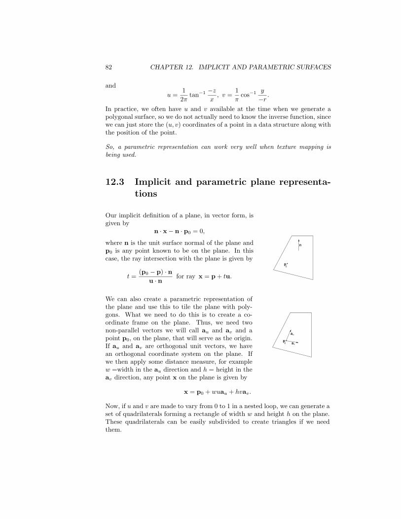
Our implicit definition of a plane, in vector form, isgiven by
n · x− n · p0 = 0,
where n is the unit surface normal of the plane andp0 is any point known to be on the plane. In thiscase, the ray intersection with the plane is given by
t =(p0 − p) · n
u · nfor ray x = p + tu.
p0
au
av
We can also create a parametric representation ofthe plane and use this to tile the plane with poly-gons. What we need to do this is to create a co-ordinate frame on the plane. Thus, we need twonon-parallel vectors we will call au and av and apoint p0, on the plane, that will serve as the origin.If au and av are orthogonal unit vectors, we havean orthogonal coordinate system on the plane. Ifwe then apply some distance measure, for examplew =width in the au direction and h = height in theav direction, any point x on the plane is given by
x = p0 + wuau + hvav.
Now, if u and v are made to vary from 0 to 1 in a nested loop, we can generate aset of quadrilaterals forming a rectangle of width w and height h on the plane.These quadrilaterals can be easily subdivided to create triangles if we needthem.


![Polygonization of implicit surfaces using Delaunay ... · Figure 1: Some steps of the adaptive algorithm presented in section 3. Implicit surfaces [6], or F-Reps [3] represent surfaces](https://static.fdocuments.in/doc/165x107/5eb842c88b9d8c67e84f01c2/polygonization-of-implicit-surfaces-using-delaunay-figure-1-some-steps-of-the.jpg)


