Diagnosis of Power Transformer Faults based on Five Fuzzy ...
Upload
ijera-editorCategory
view
225download
0description

Y V Aruna Int. Journal of Engineering Research and Applications www.ijera.com
ISSN : 2248-9622, Vol. 5, Issue 1( Part 4), January 2015, pp.45-50
www.ijera.com 45 | P a g e
Implementation of Transformer Protection by Intelligent
Electronic Device for Different Faults
Y V Aruna, Beena S (Assistant Professors, Department of EEE, Cambridge Institute of Technology, Bangalore-36)
ABSTRACT Protection of power system equipments was traditionally done by using electromagnetic relay, static relays, and
numerical relays. At present the microprocessor based relays are replacing the old Electromagnetic relays
because of their high level accuracy and fast operation. RET670(Transformer protection relay ), an IED
(INTELLIGENT ELECTRONIC DEVICE) provides fast and selective protection, monitoring, and control of all
types of transformer. The configured IED is tested under different fault conditions simulated by using mobile test
kit to ensure IED’s reliable operation on site. With preconfigured algorithms, the IED will automatically
reconfigure the network in case of a fault, and a service restoration is carried out within milliseconds by giving
trip signal to the corresponding Circuit breakers. On receiving the trip signal the circuit breaker operates
providing quicker isolation of transformers under the fault condition. This enables to have a complete and an
adequate protection to the specified power transformer.
Keywords – Transformer protection, IED, RET670
I. INTRODUCTION An Intelligent Electronic Device (IED) is a
term used in the electric power industry to describe
microprocessor-based controllers of power system
equipment, such as circuit breakers and transformers.
1. RET670 Introduction
RET670 provides fast and selective protection,
monitoring and control for two- and three-winding
transformers, autotransformers, generator-
transformer units, phase shifting transformers, special
railway transformers and shunt reactors. The
transformer IED is designed to operate correctly over
a wide frequency range in order to accommodate
power system frequency variations during
disturbances and generator start-up and shut-down as
in Fig.1
A very fast differential protection function with
settable CT ratio matching and vector group
compensation makes this IED the ideal solution even
for the most demanding applications. Since RET670
has very low requirements on the main CTs, no
interposing CTs are required. It is suitable for
differential applications with multi-breaker
arrangements with up to six restraint CT inputs. The
differential protection function is provided with 2nd
harmonic and wave-block restraint features to avoid
tripping for magnetizing inrush current, and 5th
harmonic restraint to avoid tripping for over
excitation. The differential function offers a high
sensitivity for low-level internal faults. The unique
and innovative sensitive differential protection
feature of the RET670 provides the best possible
coverage for winding internal turn-to-turn faults,
based on the theory of symmetrical components.
Fig.1: Internal Conventions of the directionality in
the IED.
Tripping from pressure relief/Buchholz and
temperature devices can be done through the
transformer IED where pulsing, lock-out contact
output and so on, is performed. The binary inputs are
heavily stabilized against disturbance to prevent
incorrect operations at for example dc system
capacitive discharges or DC earth faults. The
transformer IED can also be provided with a full
control and interlocking functionality including
Synchrocheck function to allow integration of the
main and/or a local back-up control. Out of Step
function is available to separate power system
sections close to electrical centre at occurring out of
step.
RET670 can be used in applications with the IEC
61850-9-2LE process bus with up to two Merging
Units (MU) as in fig1.1. Each MU has eight analogue
channels, normally four current and four voltages.
Conventional and Merging Unit channels can be
mixed freely in your application.
RESEARCH ARTICLE OPEN ACCESS

Y V Aruna Int. Journal of Engineering Research and Applications www.ijera.com
ISSN : 2248-9622, Vol. 5, Issue 1( Part 4), January 2015, pp.45-50
www.ijera.com 46 | P a g e
1.1RET 670 hardware
Fig.1.1 Rear side view of RET670
1.1.1 Available functions of RET670
Differential protection, Distance protection,
Current protection, Voltage protection, Frequency
protection, Multipurpose protection, Control, Logic,
Metering, Monitoring, Station communication etc are
the functions carried out by RET670.
II. Block diagram The block diagram in fig.2 shows the
implementation of RET670 in transformer protection
Fig.2. Block Diagram of Implementation of RET670
in transformer protection.
PCM600 is a connectivity package which
provides the means for system products and tools to
connect and interact with the IED in an efficient way
as well as data to allow efficient engineering of
system products. RET670 supports IEC 61850
standard. Configuration of RET670 is done by using
signal matrix tool of PCM600, generating a .pcmi
file. After establishing communication with RET670
the .pcmi file is uploaded to RET670 and then the
parameter setting is done as per the required
transformer protection scheme.
The CT’s and VT’s will provide the necessary
actuating signals to RET670 under the fault
condition. Operation of RET670 gives the trip signal
to the physical trip coils. When once the IED is
configured for different protection schemes the fault
voltage is applied by simulating the fault condition
through Mobile test kit.)
2.1. Protection and Control Manager (PCM 600)
with Connectivity Package for Relay.
PCM600 is used to do complete engineering and
configuration activities needed for the IEDs. Product
type and version specific engineering data needed by
PCM600 for protection, control and communication
engineering of a particular IED is given in an IED
connectivity package. A PC with PCM600 can be
connected to any 670 series IED within a station
using the Ethernet connection. The connection allows
to reading and writing all configuration data needed
for proper operation from or to the IED. The IEDs
have communication interfaces for protocols and
media used for station communication. IED
IEC-61850 station communication files can export
from PCM600 to station engineering tools for
engineering of station communication between bay
IEDs and station IEDs.
2.1.1 Tasks of PCM600 in IED engineering
process
IED engineering management ,Communication
engineering, Disturbance record management
Service management are the tasks of PCM600 in IED
engineering process.
2.1.2 Available Protection
The following are the few among the various
protections which is provided to the above mentioned
transformer by an IED, RET670.
i. Two winding differential protection.
ii. High impedance differential protection
(REF).
iii. Over current and Earth fault protection.
iv. Over excitation protection.
v. Transformer troubles.
III. TWO WINDING DIFFERENTIAL
PROTECTION The task of the power transformer differential
protection is to determine whether a fault is within
the protected zone, or outside the protected zone. The
protected zone is delimited by the position of current
transformers , and in principle can include more
objects than just transformer. If the fault is found to
be internal, the faulty power transformer must be
quickly disconnected. Thus the IED will always
internally measure the currents on all sides of the
power transformer with the same reference direction
towards the power transformer windings.
3.1 Configuration
The functions Transformer differential
protection, two-winding (T2WPDIF) is provided with
internal CT ratio matching and vector group
compensation and when required zero sequence
current elimination is also made internally in the
software. T2WPDIF is the functional block of two
winding differential protection.
Y V Aruna Int. Journal of Engineering Research and Applications www.ijera.com
ISSN : 2248-9622, Vol. 5, Issue 1( Part 4), January 2015, pp.45-50
www.ijera.com 47 | P a g e
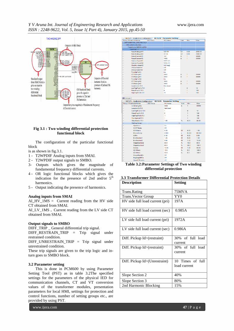
Fig 3.1 : Two winding differential protection
functional block
The configuration of the particular functional
block
is as shown in fig.3.1.
1 - T2WPDIF Analog inputs from SMAI.
2 - T2WPDIF output signals to SMBO.
3- Outputs which gives the magnitude of
fundamental frequency differential currents.
4 - OR logic functional blocks which gives the
indication for the presence of 2nd and/or 5th
harmonics.
5 - Output indicating the presence of harmonics.
Analog inputs from SMAI
AI_HV_1MS = Current reading from the HV side
CT obtained from SMAI.
AI_LV_1MS = Current reading from the LV side CT
obtained from SMAI.
Output signals to SMBO
DIFF_TRIP _ General differential trip signal.
DIFF_RESTRAIN_TRIP = Trip signal under
restrained condition.
DIFF_UNRESTRAIN_TRIP = Trip signal under
unrestrained condition.
These trip signals are given to the trip logic and in-
turn goes to SMBO block.
3.2 Parameter setting
This is done in PCM600 by using Parameter
Setting Tool (PST) as in table 3.2The specified
settings for the parameters of the physical IED for
communication channels, CT and VT conversion
values of the transformer modules, presentation
parameters for local HMI, settings for protection and
control functions, number of setting groups etc., are
provided by using PST.
Table 3.2:Parameter Settings of Two winding
differential protection
3.3 Transformer Differential Protection Details
Description Setting
Trans.Rating 75MVA
Trans.Vector Group YY0
HV side full load current (pri) 197A
HV side full load current (sec) 0.985A
LV side full load current (pri) 1972A
LV side full load current (sec) 0.986A
Diff. Pickup Id>(restraint) 30% of full load
current
Diff. Pickup Id>(restraint) 30% of full load
current
Diff. Pickup Id>(Unrestraint) 10 Times of full
load current
Slope Section 2 40%
Slope Section 3 80%
2nd Harmonic Blocking 15%

Y V Aruna Int. Journal of Engineering Research and Applications www.ijera.com
ISSN : 2248-9622, Vol. 5, Issue 1( Part 4), January 2015, pp.45-50
www.ijera.com 48 | P a g e
3.4 Testing procedure
When once the complete configuration of an IED
is done it is tested for its operation and reliability by
using mobile test kit (Doable, Omicron).
Differential protection test is classified based on
the parameters which are to be checked. They are,
i. Pick up test
ii. Stability test
iii. Slope test
3.4.1. PICK UP TEST
Pick up test is done to verify the pick-up value of
the relay on both HV and LV side of the
transformeras in fig 3.4.1 & 3.4.1.1.
For a 75MVA, 220kV/22kV power transformer,
HV tripping value = 0.985A
We have Idmin = 0.3
Therefore, HV pick up = 0.985 * 0.3 = 0.295A
Similarly,
LV tripping value = 0.984A
We have Idmin = 0.3
Therefore, LV pick up = 0.984 * 0.3 = 0.295A
This value of current is injected to the relay for
each one of the phases and also for all the three phase
by using Doble or omicron test kit and is checked for
its reliability. Pick up value of current is been
injected to the R phase of HV as in table3.4.1.2 & for
LV side as in table 3.4.1.3. As soon as the injected
current exceeds 295mA the relay gets tripped.
Table 3.4.1Testing procedure for 1- Phase
Table 3.4.1.1 Testing procedure for 3- Phase
3.4.1.2 PICK UP TEST MEASURED IN 1Φ
INJECTION
Phase
INJECTE
D
CURREN
T(HV
SIDE)
OPERATIN
G
TIME(MS)
DIFFERENTIA
L CURRENT
BIAS
CURR
ENT
R-PH 0.295 26.3 59 59.09
Y-PH 0.296 29.3 59 59.18
B-PH 0.295 27.2 59 59.99
TABLE 3.4.1.2 PICKUP TEST TABULATION ON HV
SIDE
Phase
INJECTED
CURRENT
(LV SIDE)
OPERATIN
G
TIME(MS)
DIFFERENTIA
L CURRENT
BIAS
CURR
ENT
R-PH 0.294 26.1 59 59.29
Y-PH 0.293 29.8 59 59.37
B-PH 0.295 27.1 59 59.93
TABLE 3.4.1.3 PICKUP TEST TABULATION ON LV
SIDE
3.4.2. STABILITY TEST
This test is done to check the stability of the
relay. The transformer under consideration is a Y-Y
connected transformer with 0 degree phase shift. An
equal current of magnitude 1A is been injected to
both HV and LV (when both HV and LV has CTs of
same ratio) or current of magnitude equal to the pick-
up value of HV and LV respectively is been injected.
The phase angle of any one of the phases of either
HV or LV is changed. When once the current goes
out of phase the relay is tripped. This is indicated by
indication LED as in the Figure 3.4.2. 75MVA,
220kV/22kV power transformer has different CT
ratios of HV and LV is different. Hence, the actuating
value of 0.295A is been injected for R phase of HV
and LV. Since the phase angles are balanced the relay
is under stable state.When once the phase angle of
either HV or LV is changed the currents become out
of phase issuing a trip.
TABLE 3.4.2 TESTING PROCEDURE FOR STABILITY
TEST

Y V Aruna Int. Journal of Engineering Research and Applications www.ijera.com
ISSN : 2248-9622, Vol. 5, Issue 1( Part 4), January 2015, pp.45-50
www.ijera.com 49 | P a g e
3.4.2.1 STABILITY TEST RESULTS
Phase
INJECTED
CURRENT(HV
SIDE)
INJECTED
CURRENT(HV
SIDE)
STABI
LITY
CURR
ENT
PHASE
(DEG)
CURR
ENT
PHASE
(DEG)
R-PH 1A 00 1A 180
0 OK
Y-PH 1A 2400 1A 60
0 OK
B-PH 1A 1200 1A 300
0 OK
Table 3.2.2.1 Stability Test Tabulation
3.4.3. SLOPE TEST
The operate restrain characteristic has three
regions. One is non operating region in which the
relay won’t operate. Operating region in which the
relay operates but conditionally. The unrestrained
region in which the relay is operated unconditionally.
This operation of the relay is verified by conducting
slope test as in fig3.4.3.
3.4.3 Fault currents with DC offset during an
external fault Slope = (ΔIoperate/ ΔIrestrain) *100
3.4.3.1 SLOPE TEST(HV&LV) RESULTS FOR
SLOPE-1
Current injected as below:
Current injected at HV side and LV side 2 times
of full load current and LV side current is reduced.
Table 3.4.3.1 Slope-1 Test Results
3.4.3.2 CALCULATION:
3.4.3.3 SLOPE TEST(HV&LV) RESULTS
FOR SLOPE-2
Current injected as below:
Current injected at HV side and LV side 2 times of
full load current and LV side current is reduced.
Table 3.4.3.3 Slope-2 Test Results
3.4.3.4 CALCULATION:
IV. APPLICATIONS The protection and control IEDs have many
functions included. They included self supervision
with internal event list function block provides good
supervision of the IED. The fault signals make it
easier to analyze and locate a fault.
Both hardware and software supervision is
included and it is also possible to indicate possible
faults through a hardware contact on the power
supply module and/ or through the software

Y V Aruna Int. Journal of Engineering Research and Applications www.ijera.com
ISSN : 2248-9622, Vol. 5, Issue 1( Part 4), January 2015, pp.45-50
www.ijera.com 50 | P a g e
communication. Internal events are generated by the
built-in supervisory functions. The supervisory
functions supervise the status of the various modules
in the IED and, in case of failure, a corresponding
event is generated. Similarly, when the failure is
corrected, a corresponding event is generated.
V. CONCLUSION The Protection Scheme with a particular rating of
the transformer has been designed. For that rating of
the transformer the CT ratio on primary and
secondary sides are calculated and by using that ratio
HV and LV tripping values are calculated. Now by
using PCM600 Connectivity Package the
configuration is done.
In PCM600 there are different functional blocks
by using those functional blocks the configuration for
different faults is done according to the scheme .The
harmonic effect and stable operation regions are also
taken into consideration. once the configuration is
done it is tested using doble or omicron and
parameter setting are done. The test involves pickup
test, slope test, stability test etc..the protection for
different faults have been done. Hence by doing this,
the protection system has become more reliable and
efficient. The transformer is protected against
different faults by Intelligent electronic device.
References [1] Å. Carlson, “Power Transformer Design
Fundamentals”, ABB Transformers,
Ludvika 2000-08-25.
[2] A. R. van C. Warrington, Protective Relays:
Their Theory and Practice, Volume One and
Two, London: Chapman and Hall, 1962 &
1969.
[3] ABB Document 1MRK 504 086-UEN,
"Technical reference manual, Transformer
Protection IED RET 670", Product version:
1.1, ABB Power Technologies AB,
Västerås, Sweden, Issued: March 2007
[4] J.A.B. Elston, Methods and Apparatus for
Differential Current Measurement in a
three-phase power system, U.S. Patent
6,507,184; 2003-01-14.
Journal Papers:
[1] A.G. Phadke, J.S. Thorp “A New Computer-
Based Flux-Restrained Current-Differential
Relay for Power Transformer Protection”,
IEEE Transactions on Power Apparatus and
Systems Volume PAS-102, Issue 11, pp.
3624-3629, Nov. 1983.
[2] K. Tian, P. Liu “Improved Operation of
Differential Protection of Power
Transformers for Internal Faults Based on
Negative Sequence Power”, IEEE
Proceedings of EMPD’98 Conference, Vol.
2, pp. 422-425, March 1998.
Books:
[1] ABB Book, “Transformer Handbook”1LAC
000 010 ABB Power Technologies
Management Ltd. Transformers
Switzerland.
[2] Transformer Book, Tampere University of
Technology, (http://www.e-leeh.org/transfor
mer/)