
Implementation of PLC Remote Control System Based …file.scirp.org/pdf/16-4.18.pdfIPC is shown in...
5
Implementation of PLC Remote Control System Based on High-Speed Data Communication Card Jiang Wei-jie 1 , Lin Feng 2 1,2. College of Electrical Engineering, Zhejiang University, Hangzhou310027, China 1. e-mail [email protected], 2. e-mail [email protected] Abstract: According to the requirement of the engineering project, which is to realize the remote control function of automatic system based on Programmable Logic Controller (PLC), we adopt RS485 high-speed data communication card of Advantech to achieve the excellent performance of control PLC in the distance via remote Industrial Personal Computer (IPC). The rise and rotate platform structure, especially its control system, is described in detail. The realization of the long-distance communications between IPC and PLC is also showed in this paper. The excellent real-time effect, the speediness and effective remote control per- formance are presented in the test. Keywords: PLC; RS485; high-speed data communication card 1 Introduction In industrial control systems, the application of PLC, inverter and IPC has been used widely. Generally, IPC is the core part of the system, and it makes use of output point of PLC to drive relay to control the start, stop, speed and accurate position of the drive system and so on. This paper describes the combination of the Mitsu- bishi FX2N Series PLC and inverter, to achieve the con- trol performance of the rise and rotate platform structure system. We regulate and control the whole system by using Mitsubishi PLC and its special function modules. After accomplishing the process of collecting the sensor signals from engineering, signal conversion, data proc- essing and communications, the system can be controlled effectively. And the implementation of monitoring and management of the system is completed by using FORCE CONTROL software in the IPC. The industrial computer (IPC) is used as the main control unit (host computer), and the real-time control circuit that is con- sisted of PLC is used as the implementation unit (slave computer). Taking into account some factors such as cost-effectiveness, we use power inverters in this system. We adopt RS485 communication card to accomplish the remote control functions. The features of high an- ti-interference ability, long transmission distance and low price can be obtained by this way. We can realize the remote control function of PLC, and realize the functions of start/stop operation of inverter by using one single communication line, etc. [1]. At the same time, in order to achieve rapid and effective control performance, IPC is equipped with a high-speed data communication card. 2 System Configuration The rise and rotate platform structure is a control system designed for the acoustic measurement unit, whose main function is that it made the measured device which is hung on the structure move in level direction, vertical direction and rotational direction, as is shown in Figure 1. The control performance of measured object is achieved by the PLC through the operation of the motor controller, while the current location of the object is sending to high-speed pulse counting modules through encoder. This feedback signal is to ensure accurate posi- tioning. IPC plays the role of control unit in the system; the touch screen and liquid crystal display play the role of display unit; while a variety of motors and their con- trollers play the role of executive body. According to the input and output points of specific requirements in pro- ject, we select FX2N-32MR of the Mitsubishi PLC series. In this system, we utilize the excellent performance of combination of high- speed data communication card and RS485 communications, and realize fast and effective control performance of remote control between IPC and PLC. The picture of the rise and rotate platform structure is shown in Figure 2, and the metal cabinet is its console. From Figure 1, we can see that rapid RS485 commu- nication is made between remote IPC and PLC. 674 Proceedings of 14th Youth Conference on Communication 978-1-935068-01-3 © 2009 SciRes.
Transcript of Implementation of PLC Remote Control System Based …file.scirp.org/pdf/16-4.18.pdfIPC is shown in...

Implementation of PLC Remote Control System Based on High-Speed Data Communication Card
Jiang Wei-jie1, Lin Feng2
1,2. College of Electrical Engineering, Zhejiang University, Hangzhou310027, China
1. e-mail [email protected], 2. e-mail [email protected]
Abstract: According to the requirement of the engineering project, which is to realize the remote control function of automatic system based on Programmable Logic Controller (PLC), we adopt RS485 high-speed data communication card of Advantech to achieve the excellent performance of control PLC in the distance via remote Industrial Personal Computer (IPC). The rise and rotate platform structure, especially its control system, is described in detail. The realization of the long-distance communications between IPC and PLC is also showed in this paper. The excellent real-time effect, the speediness and effective remote control per-formance are presented in the test.
Keywords: PLC; RS485; high-speed data communication card
1 Introduction
In industrial control systems, the application of PLC,
inverter and IPC has been used widely. Generally, IPC is
the core part of the system, and it makes use of output
point of PLC to drive relay to control the start, stop,
speed and accurate position of the drive system and so
on.
This paper describes the combination of the Mitsu-
bishi FX2N Series PLC and inverter, to achieve the con-
trol performance of the rise and rotate platform structure
system. We regulate and control the whole system by
using Mitsubishi PLC and its special function modules.
After accomplishing the process of collecting the sensor
signals from engineering, signal conversion, data proc-
essing and communications, the system can be controlled
effectively. And the implementation of monitoring and
management of the system is completed by using
FORCE CONTROL software in the IPC. The industrial
computer (IPC) is used as the main control unit (host
computer), and the real-time control circuit that is con-
sisted of PLC is used as the implementation unit (slave
computer).
Taking into account some factors such as
cost-effectiveness, we use power inverters in this system.
We adopt RS485 communication card to accomplish the
remote control functions. The features of high an-
ti-interference ability, long transmission distance and low
price can be obtained by this way. We can realize the
remote control function of PLC, and realize the functions
of start/stop operation of inverter by using one single
communication line, etc. [1]. At the same time, in order
to achieve rapid and effective control performance, IPC
is equipped with a high-speed data communication card.
2 System Configuration
The rise and rotate platform structure is a control
system designed for the acoustic measurement unit,
whose main function is that it made the measured device
which is hung on the structure move in level direction,
vertical direction and rotational direction, as is shown in
Figure 1. The control performance of measured object is
achieved by the PLC through the operation of the motor
controller, while the current location of the object is
sending to high-speed pulse counting modules through
encoder. This feedback signal is to ensure accurate posi-
tioning. IPC plays the role of control unit in the system;
the touch screen and liquid crystal display play the role
of display unit; while a variety of motors and their con-
trollers play the role of executive body. According to the
input and output points of specific requirements in pro-
ject, we select FX2N-32MR of the Mitsubishi PLC series.
In this system, we utilize the excellent performance of
combination of high- speed data communication card and
RS485 communications, and realize fast and effective
control performance of remote control between IPC and
PLC. The picture of the rise and rotate platform structure
is shown in Figure 2, and the metal cabinet is its console.
From Figure 1, we can see that rapid RS485 commu-
nication is made between remote IPC and PLC.
674
Proceedings of 14th Youth Conference on Communication
978-1-935068-01-3 © 2009 SciRes.

Figure 1 system configuration
Figure 2 the picture of the rise and rotate platform structure
Three-dimensional FORCE CONTROL software that
installed on IPC is responsible for the operation of the
monitoring system. At the same time, IPC exchanges
data with the PLC through a dedicated protocol (Mitsu-
bishi MELSEC). The remote IPC realizes the control
function of PLC on the spot with FORCE CONTROL
software through the serial port of the high-speed data
communications card. The control performance of the
whole system is achieved. In addition, the touch screen
controls PLC through RS232 communication on the spot.
3 Design of PLC (slave computer)
3.1 The parameters setting of PLC
In this system, we use a dedicated communication
protocol-Mitsubishi MELSEC, and set some needed pa-
rameters, which include the following special registers:
the register of communication format (D8120), the regis-
ter of the principal and subordinate site settings (D8121).
In the use of GX-Developer programming software, the
above parameters can be set in the PLC parameters. We
adopt a dedicated protocol: data length is 7 bit, even par-
ity, stop bit is a bit, baud rate is 9600bps, H/W type is
RS485, inspection type is the total number inspection,
and the transfer control order is format 4. The above pa-
rameters are stored while the main program is written
into the PLC.
3.2 Software design of PLC
Communication parameters’ setting is completed,
and then we make a program design for the communica-
tion data (analogs and switches) between IPC and the
PLC. Especially the three modules: A/D, D/A and
high-speed pulse counting module, they do not have any
CPU unit. In order to make them work together with the
main module, we must determine the address of data
storage and channel. A/D conversion process: we use TO
instructions, write the A/D conversion control instruc-
tions into the buffer memory, which starts the module's
A/D conversion. Conversion results are stored in the
buffer memory, FROM instructions can read the results
into the PLC. The conversion process of D/A and
FX2N-1HC also only needs TO instructions to control,
FROM instructions to read digital results. In the process,
the pulse type conversion of encoder that on the spot
must be considered.
At this point, MELSEC communication protocol
allows PLC to participate in the exchange of information
passively. It means that PLC receives orders from the
host computer, which will automatically analyze the code,
check the data format, implement the corresponding op-
erations following the instructions, and return the corre-
sponding response messages.
4 Design of IPC (host computer)
Host computer communication means the commu-
nication between the IPC and PLC. There are several
ways of realization: call API serial communication func-
tion [2], use MSComm control component [3] and
SPComm control component [4]. In the control system,
we adopt VC++ to call DbCom control component (a
standard OLE control component), achieve the data ex-
change performance between database of FORCE
CONTROL soft- ware and VC++, and realize the com-
RS485
RS232
RS485
FX2N PLC
Encoder 1, 2
Level Unit(X, Y
direction)
Inverter and Motor 1, 2
Inverter and Motor 3, 4
Inverter and Motor 5
Vertical Unit(Z
direction)
Rotational Unit(Θ
direction)
Encoder 3, 4 Encoder 5
Remote IPC LCD
Touch Screen
675
Proceedings of 14th Youth Conference on Communication
978-1-935068-01-3 © 2009 SciRes.

munications with operation spot. In order to control var-
ious operating conditions of PLC and the state of con-
trolled objects more distinctly, taking into account the
actual operation needs of the control system, we adopt
FORCE CONTROL software to monitor the whole sys-
tem. The communication protocol between FORCE
CONTROL software and PLC is a PPI protocol. FORCE
CONTROL software accesses to the relevant register
addresses of PLC through the serial port, obtains the sta-
tus of the object that controlled by PLC, and modifies the
state value of the relevant register. Actually, the pro-
gramming process does not need the procedures of
read-write PLC register [5]. When FORCE CONTROL
software needs to choose address for the IO configura-
tion settings, the address settings must be the same as the
aforementioned PLC site parameters.
Figure 3 the main interface of force control software
Interface of the control system is shown in Figure 3.
Figure 3 is the main interface of FORCE CONTROL
software when we log in the control system from IPC,
including data reading area, setting area, alarm zones of
X, Y, Z and Θ and start, stop button.
5 Options of Serial Communication and Se-rial Ports
5.1 Communication mode
FX series PLC supports four kinds of communica-
tions: n: n network type, parallel connection type, no
protocol in communication and computer connection
type. In this system, we adopt Mitsubishi MELSEC. It is
a dedicated communication protocol of computer con-
nection type that Mitsubishi Corporation provides for
users [6]. Protocol type includes format 1 and format 4
(the type adopted by PLC).
5.2 Communication types and the corresponding response time experiments
5.2.1 RS232 seri al c ommunication t hrough pr o-grammable port
At present, PLC of various manufacturers is
equipped with a programmable port. We can utilize the
idle state of this port, make a connection from IPC to
PLC through a programming cable, and achieve RS232
serial communication between them. In this plan, the
response time of PLC while receiving the command from
IPC is shown in Figure 4.
Figure 4 the experiment result of RS232 serial communication through programmable port
5.2.2 RS485 serial communication through 232 serial port and RS232/RS485 serial converter
Compared with RS232, RS485 possesses the ad-
vantages of stable signal and long distance communica-
tion. In RS485 standard, a method is to adopt a
RS232/RS485 converter to make a connection from IPC
232 serial port to the 485BD of PLC and achieve RS485
standard communication. In this plan, we record the re-
sponse time of PLC when it receives the command from
IPC.
5.2.3 RS485 serial communication through 485 serial ports
In RS485 standard, another method is to utilize IPC
485 serial port to make a connection with 485BD of PLC
676
Proceedings of 14th Youth Conference on Communication
978-1-935068-01-3 © 2009 SciRes.
and achieve RS485 standard communication. In this plan,
we record the response time of PLC when it receives the
command from IPC.
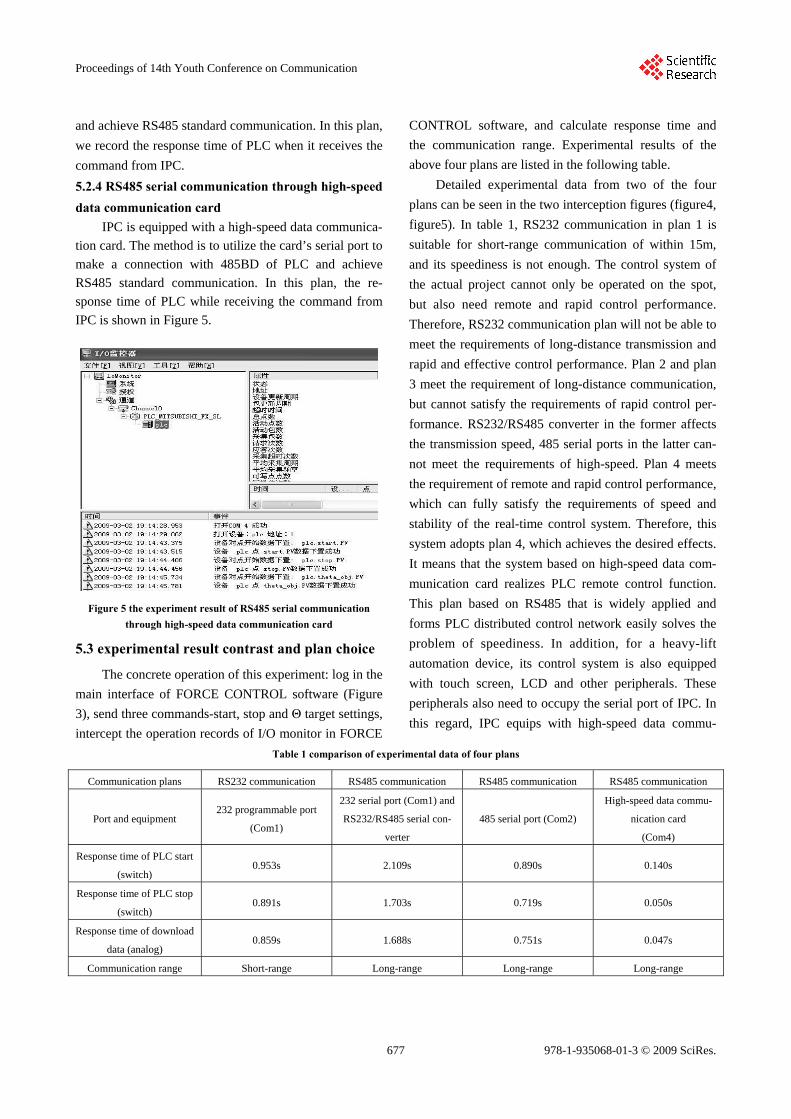
5.2.4 RS485 serial communication through high-speed data communication card
IPC is equipped with a high-speed data communica-
tion card. The method is to utilize the card’s serial port to
make a connection with 485BD of PLC and achieve
RS485 standard communication. In this plan, the re-
sponse time of PLC while receiving the command from
IPC is shown in Figure 5.
Figure 5 the experiment result of RS485 serial communication through high-speed data communication card
5.3 experimental result contrast and plan choice
The concrete operation of this experiment: log in the
main interface of FORCE CONTROL software (Figure
3), send three commands-start, stop and Θ target settings,
intercept the operation records of I/O monitor in FORCE
CONTROL software, and calculate response time and
the communication range. Experimental results of the
above four plans are listed in the following table.
Detailed experimental data from two of the four
plans can be seen in the two interception figures (figure4,
figure5). In table 1, RS232 communication in plan 1 is
suitable for short-range communication of within 15m,
and its speediness is not enough. The control system of
the actual project cannot only be operated on the spot,
but also need remote and rapid control performance.
Therefore, RS232 communication plan will not be able to
meet the requirements of long-distance transmission and
rapid and effective control performance. Plan 2 and plan
3 meet the requirement of long-distance communication,
but cannot satisfy the requirements of rapid control per-
formance. RS232/RS485 converter in the former affects
the transmission speed, 485 serial ports in the latter can-
not meet the requirements of high-speed. Plan 4 meets
the requirement of remote and rapid control performance,
which can fully satisfy the requirements of speed and
stability of the real-time control system. Therefore, this
system adopts plan 4, which achieves the desired effects.
It means that the system based on high-speed data com-
munication card realizes PLC remote control function.
This plan based on RS485 that is widely applied and
forms PLC distributed control network easily solves the
problem of speediness. In addition, for a heavy-lift
automation device, its control system is also equipped
with touch screen, LCD and other peripherals. These
peripherals also need to occupy the serial port of IPC. In
this regard, IPC equips with high-speed data commu-
Table 1 comparison of experimental data of four plans
Communication plans RS232 communication RS485 communication RS485 communication RS485 communication
Port and equipment 232 programmable port
(Com1)
232 serial port (Com1) and
RS232/RS485 serial con-
verter
485 serial port (Com2)
High-speed data commu-
nication card
(Com4)
Response time of PLC start
(switch) 0.953s 2.109s 0.890s 0.140s
Response time of PLC stop
(switch) 0.891s 1.703s 0.719s 0.050s
Response time of download
data (analog) 0.859s 1.688s 0.751s 0.047s
Communication range Short-range Long-range Long-range Long-range
677
Proceedings of 14th Youth Conference on Communication
978-1-935068-01-3 © 2009 SciRes.

nication card of Advantech (PCL-745B), which satisfies
the requirements of rapid control performance and solves
the resource constraint problems of serial port simulta-
neously.
5.4 Settings and connection rea lization of high-speed d ata commun ication card of Advan-tech
PCL-745B communication card is a high- speed da-
ta communication card of PCL series based on the ISA's
structure. After connecting with the industrial computer
hardware, this card’s setting must be paid attention to.
Number 10 of CH#1's IRQ should be put on a short- cir-
cuit ring, which means we set it to shut down; number 5
of CH#2’s IRQ should be put on a short-circuit ring. In
addition, the port address settings should be accurate and
communication mode should be RS485. Finally, RDA
connects SDA and TX+, RDB connects SDB and TX-.
RDA, RDB, SDA and SDB are the parts of
FX2N-485BD module, TX+ and TX- are the parts of
PCL-745B high-speed data communication card.
6 Conclusions
The rise and rotate platform structure that is de-
scribed in this paper is adapted to the needs of industrial
production and test automation. It adopts 485 high-speed
data communication card, achieves remote control per-
formance of PLC by IPC through RS485 communication,
solves the problem of remote control performance and
rapid response that automatic control system faced, and
brings a great convenience for the acoustic measurement
unit. The whole plan greatly enhances the general appli-
cability of the control system. Excellent expansibility
might make this system be applied to more complex con-
trol performance of industrial production, and the com-
munication plan also has some promotional value.
Therefore, this system has broad application prospects.
Acknowledgment
Thanks for all the persons who give me assistances
in the course of experiment and writing.
References (参考文献) [1] HE Dong-mei, Inverters and PLC's RS485 communication[J].
Electrical Applications, 2007, 26(9), P118-119 (Ch). [2] XUN Xu-song, HU Xue-mei. The realization of communication
between PLC and Host Computer[J]. Science & Technology In-formation, 2006, 25, P81-82 (Ch).
[3] WU Tao. High-speed Communication between PLC and host computer[J]. Micro-computer information, 2007, 23(12), P52-54 (Ch).
[4] PAN Feng. Design of Freeport communication between PLC and host computer[J]. Science & Technology Information, 2007, 28, P79-84 (Ch).
[5] DuToit, Chris. The design, documentation and maintenance of PLC software[J]. South African Institute of Electrical Engineers. 2006, 24(5), P53-56.
[6] ZHANG Yan-min, HOU Shou-quan, ZHANG Li-han. The ap-plication of MITSUBISHI PLC in control system[J]. Industrial Control Computer, 2005, 18 (3), P64-65(Ch).
678
Proceedings of 14th Youth Conference on Communication
978-1-935068-01-3 © 2009 SciRes.


