Cisco Intercept Architecture
36
Americas Headquarters: Cisco Systems, Inc., 170 West Tasman Drive, San Jose, CA 95134-1706 USA © 2007 Cisco Systems, Inc. All rights reserved. Cisco Service Independent Intercept Architecture Version 3.0 Version History Abstract Cisco Service Independent Intercept (SII) architecture version 3.0 was developed in response to the needs of Cisco’s service provider (SP) and Internet service provider (ISP) customers for compliance with Lawful Intercept (LI) legislation and regulations. SII provides a common approach for intercepting IP communications using existing network elements. LI is the process—not a specific regulatory requirement—by which law enforcement agencies (LEAs) conduct electronic surveillance as authorized by judicial or administrative order. Legislation and regulations are increasingly being adopted that require SPs and ISPs to design and implement their networks to explicitly support authorized electronic surveillance. Types of SPs and ISPs that are subject to LI mandates vary greatly from country to country. The Cisco Service Independent Intercept Architecture Version 3.0 document describes the implementation of an LI architecture on a Cisco IP network that uses version 2.0 of Cisco LI Management Information Base (MIB) for Voice over IP (VoIP) and IP data intercepts. This architecture is designed to support “plug-and-play” capability, which means that any architecture component can be replaced by any other Cisco SII-compliant component. Because of this flexibility in component choices, it is impractical for this document to completely describe all aspects of LI implementation for all of the possible components. Therefore, this document is intended as a high-level description of the end-to-end Cisco SII LI version 3.0 architecture including how LI works, the roles of the various components, and the available component options. The document also provides some information on design, implementation, operation, and troubleshooting of LI on a Cisco SII network. For details about the various devices such as software and memory requirements, configurations, and so forth, this document includes references to device product documentation. Version Number Date Notes 1 3/15/2006 This document was created and includes version I08 of the PacketCable Event Message Specification, BTS versions 4.4 and 4.5, and version 2.0 of Cisco LI MIB. 2 4/19/2007 This document was updated and includes version 1.5-I01 of the PacketCable Event Message Specification, BTS version 5.0, and version 2.0 of Cisco LI MIB.
description
Cisco Service Independent Intercept (SII) architecture version 3.0 was developed in response to the needs of Cisco’s service provider (SP) and Internet service provider (ISP) customers for compliance with Lawful Intercept (LI) legislation and regulations. SII provides a common approach for ntercepting IP communications using existing network elements.
Transcript of Cisco Intercept Architecture

Cisco Service Independent Intercept Architecture Version 3.0
Version History
Abstract
Cisco Service Independent Intercept (SII) architecture version 3.0 was developed in response to the needs of Cisco’s service provider (SP) and Internet service provider (ISP) customers for compliance with Lawful Intercept (LI) legislation and regulations. SII provides a common approach for intercepting IP communications using existing network elements.
LI is the process—not a specific regulatory requirement—by which law enforcement agencies (LEAs) conduct electronic surveillance as authorized by judicial or administrative order. Legislation and regulations are increasingly being adopted that require SPs and ISPs to design and implement their networks to explicitly support authorized electronic surveillance. Types of SPs and ISPs that are subject to LI mandates vary greatly from country to country. The Cisco Service Independent Intercept Architecture Version 3.0 document describes the implementation of an LI architecture on a Cisco IP network that uses version 2.0 of Cisco LI Management Information Base (MIB) for Voice over IP (VoIP) and IP data intercepts.
This architecture is designed to support “plug-and-play” capability, which means that any architecture component can be replaced by any other Cisco SII-compliant component. Because of this flexibility in component choices, it is impractical for this document to completely describe all aspects of LI implementation for all of the possible components. Therefore, this document is intended as a high-level description of the end-to-end Cisco SII LI version 3.0 architecture including how LI works, the roles of the various components, and the available component options. The document also provides some information on design, implementation, operation, and troubleshooting of LI on a Cisco SII network. For details about the various devices such as software and memory requirements, configurations, and so forth, this document includes references to device product documentation.
Version Number Date Notes
1 3/15/2006 This document was created and includes version I08 of the PacketCable Event Message Specification, BTS versions 4.4 and 4.5, and version 2.0 of Cisco LI MIB.
2 4/19/2007 This document was updated and includes version 1.5-I01 of the PacketCable Event Message Specification, BTS version 5.0, and version 2.0 of Cisco LI MIB.
Americas Headquarters:Cisco Systems, Inc., 170 West Tasman Drive, San Jose, CA 95134-1706 USA
© 2007 Cisco Systems, Inc. All rights reserved.

Cisco Service Independent Intercept Architecture Version 3.0 Contents
ContentsThis document contains the following sections:
• Business Objectives of the Cisco SII LI Architecture, page 2
• Cisco Service Independent Intercept Architecture, page 3
• Implementation of Cisco SII Lawful Intercept, page 21
• Device Configuration Files, page 22
• Verifying the Cisco SII LI Network, page 25
• Troubleshooting a Cisco SII LI Network, page 28
• Appendix, page 29
• Glossary, page 33
Business Objectives of the Cisco SII LI ArchitectureThe following sections describe the business objectives of implementing the Cisco SII LI architecture:
• Key Requirements of LI Architecture, page 2
• Business Drivers, page 3
Key Requirements of LI ArchitectureThe following are the key requirements any LI architecture must meet:
• LI must be undetectable by the intercept subject. Providing a wiretap at the customer premise equipment (CPE), or diverting the call to a conference unit where the replication would take place is not acceptable because the intercept subject can detect the LI. Sophisticated users can determine that their call has been diverted because the source and destination IP addresses do not match. Therefore, the tapping must take place on equipment that is within the domain of trust of the SP or ISP (on an edge router or access server), and must be performed along the normal path of the data.
• Multiple LEAs intercepting the same subject must not be aware of each other. This confidentiality is achieved by having a one-way flow of intercept information from the mediation device to the LEA such that no information in the flow can indicate that multiple flows to different LEAs exist. This confidentiality also implies limited access of LEAs to the SP’s or ISP’s equipment.
• Unauthorized personnel’s knowledge of and capability to perform LI must be prevented. Security mechanisms must be in place to limit unauthorized personnel from performing or knowing about wiretaps as much as possible.
• The information identifying intercepts (phone numbers, IP addresses, and so on), must be correlated with the corresponding content of the intercepts.
• The reliability of delivery of information to the LEAs must be on the same order as the original delivery of packets to customers.
2Cisco Service Independent Intercept Architecture Version 3.0

Cisco Service Independent Intercept Architecture Version 3.0 Cisco Service Independent Intercept Architecture
Business DriversSPs and ISPs are required to meet LI requirements for voice and data in a variety of countries worldwide. Communications Assistance for Law Enforcement Act (CALEA) is a public law that describes how telephony service and broadband access providers in the United States must support LI. In Europe there are a number of similar laws, including the Regulation of Investigatory Powers Act (RIPA) in the United Kingdom, the Telecom Act/Telekommunications Uberwachungsverordnung (TKUV) in Germany, the Telecom Act in France, the Criminal Code in Italy, and the Telecom Act in the Netherlands. Legal requirements and specific interfaces vary from country to country.
Four specifications define the interface to the LEAs for the purposes of meeting the CALEA requirements:
• The Telephone Industry Association Lawfully Authorized Electronic Surveillance standard developed by the Telephone Industry Association (TIA).
• The PacketCable Electronic Surveillance Specification standard.
• The Lawfully Authorized Electronic Surveillance (LAES) for Voice over Packet Technology in Wireline Telecommunications Networks and Lawfully Authorized Electronic Surveillance (LAES) for Internet Access and Services standards developed by American National Standards for Telecommunications.
See the “Related Documents” and “Standards” sections for additional information about these and other LI specifications and standards.
Cisco Service Independent Intercept ArchitectureThe following sections describe the Cisco SII version 2.0 of Cisco LI MIB architecture:
• Overview, page 3
• Network Topology, page 4
• Interfaces Between Devices, page 6
• How Cisco SII LI Architecture Works, page 8
OverviewThe SII architecture was developed in response to the needs of Cisco’s SP and ISP customers for compliance with LI legislation and regulations. SII provides a common approach for intercepting IP communications using existing network elements. The architecture addresses the key LI requirements mentioned earlier and does so in a cost-effective manner. Key features of the architecture include the following:
• Use of standard access list technology to provide the intercept.
• Encapsulation of the entire intercepted and replicated packet so that the original source and destination addresses are available (important information for intercept purposes).
• Use of a control plane for intercept that is different from call control and that prevents network operations personnel from detecting the presence of active intercepts in the network.
3Cisco Service Independent Intercept Architecture Version 3.0

Cisco Service Independent Intercept Architecture Version 3.0 Cisco Service Independent Intercept Architecture
Note A control plane defines the transport used for sending or receiving the messages that initiate the LI. Since network operations personnel cannot know that intercepts are active on the network, it is important to hide or keep separate the active intercept messages from those messages used for routine call setup. However, many SPs and ISPs routinely monitor all messages for diagnostic purposes.
• An integrated approach that limits the intercept activity to the router or gateway that is handling the target’s IP traffic and only activates an intercept when the target is accessing the network.
• No LI-related command-line interface (CLI) commands that could allow for the detection of intercept activity on a router or gateway.
• LI-related MIBs and traps sent only to t third-party equipment controlling the intercept.
• Support for multiple encapsulation and transport formats.
Note At this time, the only format implemented is the format specified in the PacketCable Electronic Surveillance Specifications that use User Datagram Protocol (UDP) frames to encapsulate duplicated packets.
Network TopologyFigure 1 shows a functional depiction of a generic IP network that supports LI of voice or data traffic.
Figure 1 Functional Depiction of a Generic LI Network
Note IRI IAP is defined as the Intercept-Related Information intercept access point and CC IAP is defined as the Communication Content intercept access point.
LI AdministrationFunction
MediationDevice
IRIIAP
Service Providernetwork
LEA network
CollectionFunction
Demarcation Pointbetween SP and
LEA responsibility
9533
3
CCIAP
4Cisco Service Independent Intercept Architecture Version 3.0

Cisco Service Independent Intercept Architecture Version 3.0 Cisco Service Independent Intercept Architecture
The following sections describe the components that are integral to the Cisco SII network:
• LI Administration Function, page 5
• Mediation Device/Delivery Function, page 5
• Intercept-Related Information Intercept Access Point, page 5
• Communication Content Intercept Access Point, page 6
• Collection Function, page 6
LI Administration Function
The SP and ISP use the LI administration function to provision intercepts by interfacing with the other components in the network. The LI administration function is responsible for provisioning components in the network, administering intercept orders, and tracking and maintaining intercept information. The LI administration function also supervises the security and integrity of the LI process by continuously auditing activity logs to ensure that only authorized intercepts are provisioned and that authorized intercepts are not disrupted.
Note Provisioning intercepts is defined as accessing a device and changing the device’s operational parameters to activate a desired function on that device.
Mediation Device/Delivery Function
The mediation device (MD) is maintained by the SP or ISP and is the center of the LI process. The MD sends configuration commands to the various IAPs to enable intercepts, receives intercept information (both IRI and CC), and delivers this information to the LEA. If more than one LEA is monitoring an intercept target, the mediation device duplicates the intercept information for each LEA. The mediation device is sometimes called the delivery function.
In some cases, the MD performs additional filtering of the information. The MD is also responsible for implementing post call completion dialed digit extraction. The MD also formats the information to be compliant with the country or technology-specific requirements for delivery to law enforcement.
Mediation devices are third-party equipment. Cisco has performed end-to-end testing with a number of mediation device vendors. A list of these vendors can be found at the following URL: http://www.cisco.com/wwl/regaffairs/lawful_intercept/index.html
Intercept-Related Information Intercept Access Point
The Intercept-Related Information intercept access point (IRI IAP) is the device that provides identification information to the mediation device. IRI for voice includes the source and destination phone numbers, IP addresses, and the time of the call. IRI IAP also includes any post call-establishment messaging such as call forwarding or three-way calling. IRI for data includes login and logout times, and source and destination IP addresses and ports. For voice intercepts, the IRI IAP is the call control entity. The call control entity can be a call agent, Session Initiation Protocol (SIP) proxy, or H.323 gateway. For data intercepts, the IRI IAP is the authentication, authorization, and accounting (AAA) server, DHCP server, or other device that has knowledge of a surveillance subject’s presence in the network.
5Cisco Service Independent Intercept Architecture Version 3.0

Cisco Service Independent Intercept Architecture Version 3.0 Cisco Service Independent Intercept Architecture
Communication Content Intercept Access Point
The Communication Content IAP (CC IAP) is the device that intercepts communication content information, replicates it, and forwards the replicated information to the mediation device. The CC IAP should be located as close to the source of the call as possible, to minimize the number of simultaneous calls the device will have to monitor, and to ensure that CC can be reliably intercepted. The edge device is the only device that can guarantee CC intercept. The CC IAP can be an edge router, a trunking gateway, or an access server.
Collection Function
The collection function is a third-party device maintained by the LEA that receives, sorts, and stores intercept information from the mediation device. The collection function may also include case management capabilities.
Interfaces Between DevicesFigure 2 shows a functional depiction of the device interfaces in a Cisco SII LI broadband services network.
Figure 2 Functional Depiction of a Cisco SII LI Network for Broadband Services
Figure 3 shows the device interfaces in the context of the specific devices that are used in a Cisco SII VoIP network.
DNSserver
LI AdministrationFunction
MediationDevice
IRIIAP
Service Providernetwork
LEA network
CollectionFunction
Demarcation Pointbetween SP and
LEA responsibility
9525
7
CCIAP
d2e2
d1
e1
a
ck
6Cisco Service Independent Intercept Architecture Version 3.0

Cisco Service Independent Intercept Architecture Version 3.0 Cisco Service Independent Intercept Architecture
Figure 3 Cisco SII Voice Intercept Device Interfaces for VoIP
Note PSTN is defined as public switched telephone network.
Table 1 describes the interfaces between devices shown in Figure 2 and Figure 3.
9525
8Targetsubscriber
Edgerouter
DNSServer
CMS
AAAServer
AccessServer
Data Targetsubscriber
d1
e1
ca
k d2 e2
d1 e1
d2d2
e2e2
MediationDevice
CollectionFunction
LEAnetwork
LIAdministration
Function
TrunkingGateway
PSTN
Table 1 Cisco SII LI Network Device Interfaces
Interface Description Description
a Authorization: administration function and mediation device
The LI administration function sends intercept provisioning information—target identifier, duration of intercept, and so on—to the mediation device.
c Content: mediation device and collection function
The mediation device delivers intercept information to the collection function. If more than one LEA is intercepting the same target, the mediation device must duplicate the intercept information to send to the collection function of each LEA. This interface must meet one of the current “safe harbor” specifications for an interface between a mediation device and a collection function.
7Cisco Service Independent Intercept Architecture Version 3.0

Cisco Service Independent Intercept Architecture Version 3.0 Cisco Service Independent Intercept Architecture
How Cisco SII LI Architecture WorksThe following sections describe how the Cisco SII LI architecture works:
• Types of Intercepts, page 9
• Initiating an Intercept, page 9
• Terminating an Intercept, page 9
• Cisco SII Voice Intercept Process Flows, page 9
• Security Considerations, page 19
• Failure Recovery, page 20
d1 IRI Delivery: IRI IAP and mediation device
This is the delivery interface. The IRI IAP uses this interface to deliver IRI to the mediation device. For voice, this delivery is according to the PacketCable Event Messages Specification document in the “Related Documents” section on page 31. For data, this delivery is Remote Authentication Dial-In User Service (RADIUS) accounting messages, DHCP transactions, or other surveillance subject identifying messages.
For voice intercepts, the IRI IAP is the call control entity (call agent, SIP proxy, or H.323 gateway). For data intercepts, the IRI IAP is the AAA server, DHCP server, or other server that knows that a surveillance subject is active in the network (or a probe monitoring traffic).
d2 CC delivery: CC IAP and mediation device
The CC IAP replicates call content (CC) and sends the content to the mediation device. The CC IAP encapsulates the packets with additional UDP and IP headers and a 32-bit call content connection identifier (CCCID) header. (See the PacketCable Electronic Surveillance Specification document in the “Related Documents” section on page 31.) The CCCID is used to associate the CC with the target.
The CCCID is included so that the mediation device can map intercepts to the appropriate warrants. Usually, the mediation device will rewrite the CCCID before forwarding intercept information to collection functions.
The CC IAP is an edge router, trunking gateway, or access server.
e1 Provisioning: mediation device and IRI IAP
The mediation device uses Secure Shell (SSH) or other secure means to provision an intercept on the IRI IAP.
e2 Provisioning: mediation device and CC IAP
The mediation device uses Simple Network Management Protocol version 3 (SNMPv3) to instruct the CC IAP to replicate CC and send the content to the mediation device. The CC IAP can be either an edge router or a trunking gateway for voice, and either an edge router or an access server for data.
k DNS Lookup: mediation device and DNS server
The mediation device queries the Domain Name Service (DNS) server to determine the fully qualified domain name (FQDN) of the CC IAP.
Table 1 Cisco SII LI Network Device Interfaces (continued)
Interface Description Description
8Cisco Service Independent Intercept Architecture Version 3.0

Cisco Service Independent Intercept Architecture Version 3.0 Cisco Service Independent Intercept Architecture
Types of Intercepts
There are two types of intercepts:
• Intercept-Related Information only—This is the most common type of intercept, which intercepts only the IRI. For voice intercepts, IRI includes the source and destination phone numbers, IP addresses, the time of the call, and any post call-establishment messaging such as call forwarding or three-way calling. For data intercepts, IRI includes login and logout times, and source and destination IP addresses. Data intercepts may also include information from the IP headers of all packets sent and received by surveillance subject including the IP addresses and ports used. This type of intercept is also referred to as Pen Register or Trap and Trace.
• Intercept-Related Information and Communication Content—Typically, a small percentage of intercepts require the capture of both IRI and CC. Intercepting CC has a substantial impact on network bandwidth and device processing power. This type of intercept is also referred to as a Full Content or, in the United States, as Title 3 intercept.
Initiating an Intercept
When a warrant is issued, the LEA physically delivers the warrant to the SP or ISP. When the SP or ISP receives the warrant, the SP or ISP uses the LI administration function to enable LI on the target specified in the warrant. If the warrant is delivered prior to the authorized start date and time, the mediation device waits until the authorized start date and time to configure the tap. Once the intercept is provisioned on the mediation device, the process of initiating individual intercepts is completely automated.
Terminating an Intercept
When a warrant is issued, the warrant includes an expiration date that is typically 30 days. This expiration date is configured on the mediation device. When the warrant expires, the mediation device automatically removes the configuration for the warrant. The mediation device provisioning interface can be used to remove a warrant before the expiration date.
Cisco SII Voice Intercept Process Flows
The following sections describe the various Cisco SII voice intercept process flows:
• Standard Cisco SII Voice Intercept, page 9
• Hairpin Cisco SII Voice Intercept, page 11
• Cisco SII Three-Way Voice Intercept, page 13
• Cisco SII Call Forward to Voice Mail Intercept, page 16
• Cisco SII Data Intercept, page 17
Standard Cisco SII Voice Intercept
Figure 4 shows the topology for a standard Cisco SII voice intercept.
Note The following figure is a high-level call flow that does not include all details of the protocol messaging involved.
9Cisco Service Independent Intercept Architecture Version 3.0

Cisco Service Independent Intercept Architecture Version 3.0 Cisco Service Independent Intercept Architecture
Figure 4 Standard Cisco SII Voice Intercept at Gateway or Aggregation Router
The following steps describe the sequence of events shown in Figure 4.
Step 1 The LEA physically delivers a court order to the network administrator who operates the LI administration function.
Step 2 The LI administration function sends a configuration to the mediation device that enters the intercept.
Step 3 The mediation device sends a configuration command to the call management server (CMS) to enable the intercept.
Step 4 The intercept target receives an incoming call.
Step 5 The CMS sends a Signaling_Start message to the mediation device.
Step 6 The mediation device sends a termination attempt message to the collection function.
Step 7 The originating gateway sends Session Definition Protocol (SDP) information to the CMS.
Step 8 The CMS sends the SDP information to the mediation device in a Media_Report message.
1466
83
TargetSubscriber
EdgeRouter
TerminatingGateway
CMS DNSServer
MediationDevice
CollectionFunction
OriginatingGateway
AdministrationFunction
LEA
1
Call12Ring13
SNMPv3 destroy
Call_Answer
QoS_Stop
SNMPv3 destroy21
10
CC 14
Query9
SDP7
4
Signaling_StartSignaling_Start 5
8
CCOpen 11
CC 15
Answer 17
ReleaseRelease 19
CCClose 22
16
6
2Court order
SNMPv3 command
Enable intercept
QoS_Reserve
Termination attempt
ConfigurationCourt order
SNMPv3 command
Incoming call
3 Enable interceptEnable intercept
Media_Report
Call_Answer
18Signaling_Stop
QoS_Stop 20Media_Report
Termination attempt
Configuration
10Cisco Service Independent Intercept Architecture Version 3.0
Cisco Service Independent Intercept Architecture Version 3.0 Cisco Service Independent Intercept Architecture
Step 9 The mediation device queries the DNS server to determine the IP address of the edge router based on the IP address of the target gateway.
Step 10 The mediation device sends an SNMPv3 command to the edge router or network access server (NAS) to initiate the intercept.
Step 11 The mediation device sends a CCOpen message with the SDP to the collection function.
Step 12 The CMS delivers the call to the terminating gateway.
Step 13 The terminating gateway rings the target phone.
Step 14 The call is connected end-to-end, and the edge router or NAS intercepts and replicates all voice packets and sends the packets to the mediation device.
Step 15 The mediation device delivers CC to the collection function.
Step 16 The CMS sends a Call_Answer message to the mediation device.
Step 17 The mediation device forwards this message as an Answer message to the collection function.
Step 18 When the parties hang up, the CMS sends a Signaling_Stop message to the mediation device.
Step 19 The mediation device forwards this message as a Release message to the collection function.
Step 20 The CMS sends a Media_Report message to the mediation device.
Step 21 When the mediation device receives the Media_Report message, the mediation device sends SNMPv3 messages to the edge router or NAS instructing the device to destroy the CC monitoring sessions and the mediation device MIB. Three destroy messages are sent: one for each of the two CC streams and one for the mediation device MIB.
Step 22 The mediation device sends a CCClose message to the collection function.
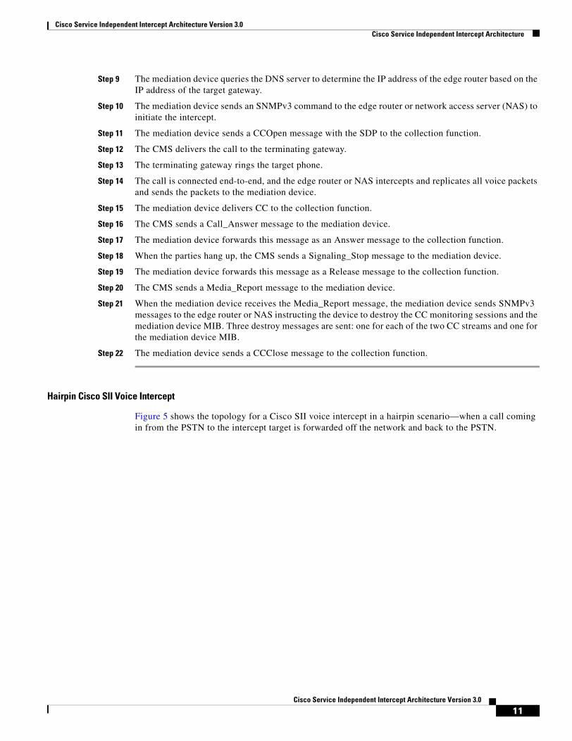
Hairpin Cisco SII Voice Intercept
Figure 5 shows the topology for a Cisco SII voice intercept in a hairpin scenario—when a call coming in from the PSTN to the intercept target is forwarded off the network and back to the PSTN.
11Cisco Service Independent Intercept Architecture Version 3.0

Cisco Service Independent Intercept Architecture Version 3.0 Cisco Service Independent Intercept Architecture
Figure 5 Hairpin Cisco SII Voice Intercept at Trunking Gateway
The following steps describe the sequence of events shown in Figure 5.
Step 1 The LEA physically delivers a court order to the network administrator that operates the LI administration function.
Step 2 The LI administration function sends a configuration to the mediation device that enters the intercept.
Step 3 The mediation device sends a configuration command to the CMS to enable the intercept.
Step 4 The intercept target activates call forwarding to an off network (off-net) number.
Step 5 The CMS informs the mediation device that the target has activated call forwarding.
Step 6 The mediation device forwards the feature activation code for call forwarding to the collection function.
Step 7 The target receives a call from the PSTN that triggers call forwarding.
Step 8 The CMS sends a Signaling_Start message to the mediation device.
TargetSubscriber
EdgeRouter
TerminatingGateway
CMS DNSServer
MediationDevice
CollectionFunction
TrunkingGateway
AdministrationFunction
LEA
1466
84
1
4
CC 15
17
5
8
10
11
6
9
14
CC 16
Answer
Call_Answer
QoS_StopAnswer 18
AnswerRelease 20
23
2
7 Call
13
3Activate forwarding
Activate forwarding
Singaling_Start
Service_Instance
QoS_Reserve
Activate forwarding
Termination attempt
CCOpen
CCClose
Court order
Configuration
SNMPv3 command
Enable interceptActivate forwarding
Call_Answer
19Signaling_Stop
QoS_Stop 21Media_Report
Activate forwarding
Singaling_Start
Service_Instance
Media_Report
Activate forwarding
Termination attempt
CCOpen
CCClose
Court order
Configuration
SNMPv3 command
22 SNMPv3 comSNMPv3 destroy
Enable intercept
12 Query
12Cisco Service Independent Intercept Architecture Version 3.0

Cisco Service Independent Intercept Architecture Version 3.0 Cisco Service Independent Intercept Architecture
Step 9 The mediation device sends a termination attempt message to the collection function.
Step 10 The CMS sends a Service_Instance message to the mediation device indicating that the call is being forwarded.
Step 11 The CMS sends a Media_Report message to the mediation device.
Step 12 The mediation device queries the DNS server to determine the IP address of the trunking gateway.
Step 13 The mediation device sends an SNMPv3 command to the trunking gateway to enable an intercept, if call content is to be intercepted, and to route the call back to the PSTN.
Note If the terminating gateway does not support SNMPv3, Media Gateway Control Protocol (MGCP) is used instead.
Step 14 The mediation device sends a CCOpen message to the collection function.
Step 15 The trunking gateway duplicates all packets and sends them to the mediation device.
Step 16 The mediation device delivers CC to the collection function.
Step 17 The CMS sends a Call_Answer message to the mediation device.
Step 18 The mediation device forwards this message as an Answer message to the collection function.
Step 19 When the parties hang up, the CMS sends a Signaling_Stop message to the mediation device.
Step 20 The mediation device forwards this message as a Release message to the collection function.
Step 21 The CMS sends a Media_Report message to the mediation device.
Step 22 When the mediation device receives the Media_Report, the mediation device sends SNMPv3 messages to the trunking gateway instructing the device to destroy the CC monitoring sessions and the mediation device MIB. Three destroy messages are sent: one for each of the CC streams and one for the mediation device MIB.
Note If MGCP was used by the mediation device to access CC, then the instruction from the CMS to delete the connection also stops CC duplication. In this case, the mediation device does not need to send any additional messages to terminate the intercept.
Step 23 The mediation device sends a CCClose message to the collection function.
Cisco SII Three-Way Voice Intercept
Figure 6 shows the topology for a Cisco SII of a three-way voice conference call.
13Cisco Service Independent Intercept Architecture Version 3.0

Cisco Service Independent Intercept Architecture Version 3.0 Cisco Service Independent Intercept Architecture
Figure 6 Cisco SII Three-Way Voice Intercept
1466
87
TargetSubscriber
EdgeRouter
TerminatingGateway
CMS DNSServer
MediationDevice
CollectionFunction
OriginatingGateway
AdministrationFunction
LEANon-TargetSubscriber 1
Non-TargetSubscriber 2
1
Call
Ring
Call_Answer
10
CC 14
CC 28
CCOpenCCOpen 11
2CCClose messages2CCClose messages 38
35
CCOpenCCOpen 25
CC 15
CC 29
AnswerAnswer 17
AnswerAnswer 31
16
2Court order
SNMPv3 command
ConfigurationCourt order
SNMPv3 command
3 Enable interceptEnable intercept
37 2 SNMPv3 destroy messages2 SNMPv3 destroy messages
24 Enable interceptSNMPv3
13
Ring27
query23
9 query
Call_Answer
Call_Answer 30Call_Answer
5Signalling StartSignalling Start
342 Call_Release Messages2 Signaling_Stop Messages
2 Call_Release Messages2 Release Messages
33Signalling Start
12
Call CMS 26
8Signalling StartMedia_Report
362 QoS_Stop Messages2 Media_Reserve Messages
19Signalling startSignalling start
22QoS_ReserveMedia_Report
4Outgoing CallOutgoing Call
18
7SDP
21SDP
6Originating attemptOriginating attempt
20origination attemptorigination attempt
Configuration
Hook flash
32 Hook flash
Service_Instance MessageService_Instance Message
14Cisco Service Independent Intercept Architecture Version 3.0

Cisco Service Independent Intercept Architecture Version 3.0 Cisco Service Independent Intercept Architecture
The following steps describe the sequence of events shown in Figure 6.
Step 1 The LEA physically delivers a court order to the network administrator that operates the LI administration function.
Step 2 The LI administration function sends a configuration to the mediation device that enters the intercept.
Step 3 The mediation device sends a configuration command to the CMS to enable the intercept.
Step 4 In this scenario, the intercept target initiates an outgoing call.
Step 5 The CMS sends a Signaling_Start message to the mediation device.
Step 6 The terminating gateway sends an originating attempt message to the mediation device.
Step 7 The terminating gateway sends SDP information to the CMS.
Step 8 The CMS sends the SDP information to the mediation device in a Media_Report message.
Step 9 The mediation device queries the DNS server to determine the IP address of the edge router based on the IP address of the target gateway.
Step 10 The mediation device sends an SNMPv3 command to the edge router to initiate the intercept.
Step 11 The mediation device sends a CCOpen message with the SDP to the collection function.
Step 12 The CMS delivers the call to the originating gateway.
Step 13 The originating gateway rings non-target subscriber 1.
Step 14 The call is connected end-to-end, and the edge router intercepts and replicates all voice packets and sends the packets to the mediation device.
Step 15 The mediation device delivers CC to the collection function.
Step 16 The CMS sends a Call_Answer message to the mediation device.
Step 17 The mediation device forwards this message as an Answer message to the collection function.
Step 18 The target hook flashes to put the Hook nontarget subscriber 1 on hold and initiate a second call.
Step 19 The CMS sends a Signaling_Start message to the mediation device.
Step 20 The terminating gateway sends an originating attempt message to the mediation device.
Step 21 The terminating gateway sends SDP information to the CMS.
Step 22 The CMS sends the SDP information to the mediation device in a Media_Report message.
Step 23 The mediation device queries the DNS server to determine the IP address of the edge router based on the IP address of the target gateway.
Step 24 The mediation device sends an SNMPv3 command to the edge router to initiate the intercept.
Step 25 The mediation device sends a CCOpen message with the SDP to the collection function.
Step 26 The CMS delivers the call to the originating gateway.
Step 27 The originating gateway rings nontarget subscriber 2.
Step 28 The call is connected end to end, and the edge router intercepts and replicates all voice packets and sends the packets to the mediation device.
Step 29 The mediation device delivers CC to the collection function.
Step 30 The CMS sends a Call_Answer message to the mediation device.
Step 31 The mediation device forwards this message as an Answer message to the collection function.
Step 32 The target hook flashes to create a three-way call.
15Cisco Service Independent Intercept Architecture Version 3.0

Cisco Service Independent Intercept Architecture Version 3.0 Cisco Service Independent Intercept Architecture
Step 33 The CMS sends a Service_Instance message indicating Three_Way_Call to the mediation device.
Step 34 When the parties hang up, the CMS sends two Signaling_Stop messages to the mediation device, one for each part of the three-way call.
Step 35 The mediation device forwards these messages as Release messages to the collection function.
Step 36 The CMS sends two Media_Report messages to the mediation device.
Step 37 When the mediation device receives the Media_Report message, the mediation device sends SNMPv3 messages to the terminating gateway instructing the device to destroy the CC monitoring sessions and the mediation device MIB. Six destroy messages are sent: three for each part of the three-way call.
Step 38 The mediation device sends two CCClose messages to the collection function.
Cisco SII Call Forward to Voice Mail Intercept
Figure 7 shows the topology for a Cisco SII of a voice call that is forwarded to voice mail.
Figure 7 Cisco SII Call Forward to Voice Mail Intercept
TargetSubscriber
EdgeRouter
TerminatingGateway
CMS DNSServer
MediationDevice
CollectionFunction
OriginatingGateway
AdministrationFunction
LEA
1466
85
1
CC 13
17
5
7
8
6
9
12
CC 14
ReleaseRelease 16
19
2
10 Query
11
3
Court order
Configuration
Court order
Configuration
Signaling_Start
Service_InstanceTermination attempt
CCOpen
CCClose
SNMPv3 command
Enable intercept
QoS_StopMedia_Report
Signaling_Start
Service_Instance
Service_Instance
QoS_Reserve
Service_Instance
Termination attempt
Media_Report
15Call_ReleaseSignaling_Stop
CCOpen
CCClose
SNMPv3 command
18 SNMPv3 destroySNMPv3 destroy
Enable intercept
4 Call
16Cisco Service Independent Intercept Architecture Version 3.0

Cisco Service Independent Intercept Architecture Version 3.0 Cisco Service Independent Intercept Architecture
The following steps describe the sequence of events shown in Figure 7.
Step 1 The LEA physically delivers a court order to the network administrator that operates the LI administration function.
Step 2 The LI administration function sends a configuration to the mediation device that enters the intercept.
Step 3 The mediation device sends a configuration command to the CMS to enable the intercept.
Step 4 The target receives a call from the PSTN that is not answered, which triggers call forwarding to voice mail.
Step 5 The CMS sends a Signaling_Start message to the mediation device.
Step 6 The mediation device sends a termination attempt message to the collection function.
Step 7 The CMS sends a Service_Instance message to the mediation device indicating that the call is being forwarded.
Step 8 The mediation device forwards the Service_Instance message to the collection function.
Step 9 The CMS sends a Media_Report message to the mediation device.
Step 10 The mediation device queries the DNS server to determine to which the IP address the call is being forwarded. When the mediation device determines the call is being forwarded to the voice mail system, the mediation device knows that the call must be intercepted on the originating side.
Step 11 The mediation device sends an SNMPv3 command to the originating gateway, to enable an intercept if call content is to be intercepted.
Step 12 The mediation device sends a CCOpen message to the collection function.
Step 13 The originating gateway duplicates all packets and sends them to the mediation device.
Step 14 The mediation device delivers CC to the collection function.
Step 15 When the caller hang up, the CMS sends a Signaling_Stop message to the mediation device.
Step 16 The mediation device forwards this message as a Release message to the collection function.
Step 17 The CMS sends a Media_Report message to the mediation device.
Step 18 When the mediation device receives the Media_Report message, the mediation device sends SNMPv3 messages to the terminating gateway instructing the device to destroy the CC monitoring sessions and the mediation device MIB. Six destroy messages are sent: three for each part of the three-way call.
Step 19 The mediation device sends a CCClose messages to the collection function.
Cisco SII Data Intercept
Figure 8 shows the topology for a typical Cisco SII data intercept. Although only an edge router is shown, this same topology applies if the target accesses the network via dialup and a NAS such as a Cisco AS 5350, Cisco AS 5400, or Cisco AS 5850.
17Cisco Service Independent Intercept Architecture Version 3.0

Cisco Service Independent Intercept Architecture Version 3.0 Cisco Service Independent Intercept Architecture
Figure 8 Cisco SII Data Intercept
The following steps describe the sequence of events shown in Figure 8.
Step 1 The LEA physically delivers a court order to the network administrator that operates the LI administration function.
Step 2 The LI administration function sends a configuration to the mediation device that enters the intercept.
Step 3 The mediation device enables the intercept on a sniffer or a probe that is configured to sniff all AAA traffic and inform the mediation device when the target subscriber authenticates in the network.
Step 4 When the target subscriber accesses the network, the target subscriber’s computer sends an access request to the AAA server.
Step 5 The mediation device is notified that the intercepted target subscriber is active in the network by the sniffer or probe monitoring the AAA server.
Step 6 The AAA server grants access to the target subscriber.
Step 7 The edge router forwards the Accounting_start message to the AAA server.
Step 8 The mediation device is notified that the intercepted target subscriber’s session has been successfully authenticated and is now active in the network.
Step 9 The mediation device sends an SNMPv3 command to the edge router, to enable the intercept when communication content is to be intercepted.
Step 10 When the data stream begins, the edge router intercepts the CC, replicates it, and forwards the stream to the mediation device.
1466
86
TargetSubscriber
EdgeRouter
AAAServer
MediationDevice
CollectionFunction
AdministrationFunction
LEA
1
4
23
Court order
Configuration
Court order
Configuration
7 ConfigurationIntercept request
Access request
Confirmation
Access request
Access request
Accounting_Start
Enable intercept
Confirmation
Access
Access
Access request
8Accounting_Start
5Intercept request
6Confirmation
11CC
12CC
14Accounting_stop
15
Enable intercept
9 SNMPv3 command
13 SNMPv3 commRelease request
10 Accounting_Start
SNMPv3 commandSNMPv3 command
18Cisco Service Independent Intercept Architecture Version 3.0

Cisco Service Independent Intercept Architecture Version 3.0 Cisco Service Independent Intercept Architecture
Step 11 The mediation device forwards the CC to the collection function.
Step 12 The target subscriber’s computer sends a release request to the edge router to disconnect the session from the network.
Step 13 The edge router sends an Accounting_stop message to the AAA server.
Step 14 The mediation device is notified that the target subscriber’s session has stopped.
Step 15 The mediation device sends an SNMPv3 command to the edge router to remove the intercept and to stop duplication of the communication content.
Security Considerations
Given the sensitive nature of lawful intercept—both from the standpoint of the need to protect sensitive data and to conceal the identities of law enforcement agencies and the intercept targets—the LI architecture must contain stringent security measures to combat the following types of threats:
• Impersonation of LEAs and mediation devices
• Privacy and confidentiality breaches
• Message forgery
• Replay attacks
Because legal intercept is expected to run on the wide-open Internet, very few assumptions should be made about how well the networks of the LEA’s and the SP’s or ISP’s can be secured. Although this document does not examine the issues of physical security, operating systems, or application hardening within the principles of the LI architecture, they are clearly important considerations. In particular, both the MD and LEA servers must be considered prime targets for attacks by hackers. Hardening measures commensurate with other highly vulnerable servers, such as key distribution and AAA servers, must be considered in any design.
The following section describes security requirements:
• Overall Security Requirements, page 19
Overall Security Requirements
All interfaces must be able to provide strong cryptographic authentication to establish the identity of the principles, and must correlate the identity of the principle with the action they are attempting to perform. That is, it is not sufficient to expect that authentication alone implies any specific authorization. Providing the ability to use strong crypto is not identical to requiring its use. Since many Cisco devices do not have crypto accelerators, actual use of crypto accelerators will be the choice of the SP or ISP, and will be dependent on how the device is deployed and its relative exposure. For devices placed in open, hostile environments (such as access routers), the SP or ISP must consider customer requirements for LI when making decisions about crypto acceleration hardware.
Because LI is an interesting target for attackers, all interfaces must perform some sort of cryptographic message integrity checking such as Hash-based Message Authentication Code (HMAC)-Message Digest 5 (MD5). Message integrity checking must also counter replay attacks. Because of privacy and confidentiality considerations, the architecture should allow for the use of encryption. Although encryption is not necessarily a requirement, it is highly recommended and may be a requirement in some LI deployments.
19Cisco Service Independent Intercept Architecture Version 3.0

Cisco Service Independent Intercept Architecture Version 3.0 Cisco Service Independent Intercept Architecture
Interface Between MD and IRI IAP: Control
SSH is used for the control interface between the MD and the IRI IAP.
Role-Based CLI Access Feature in Cisco IOS Software
Role-based CLI Access is a feature in Cisco IOS software on some platforms that allows the network administrator to define views that are a set of operational commands and configuration capabilities that provide selective or partial access to Cisco IOS EXEC and configuration mode commands. Views restrict user access to Cisco command-line interface (CLI) and configuration information; that is, a view can define what commands are accepted and what configuration information is visible. Thus, network administrators can exercise better control over access to Cisco networking devices. A lawful intercept view is predefined and allows a user to secure access to lawful intercept commands that are held within the TAP-MIB. More information regarding Role-based CLI Access feature can be found at the following URL:
http://www.cisco.com/en/US/products/ps6642/products_white_paper09186a00801ee18d.shtml
Interface Between MD and CC IAP: SNMPv3 Control
SNMPv3 View-based Access Control Model (VACM) and User-based Security Model (USM) are used for the control interface between the MD and the CC IAP. The native SNMPv3 security module mechanism must be used, and the minimum requirement is that preshared keys must be supported. The additional requirement is that the IAP must support the ability to protect the LI MIBs from disclosure or control by unauthorized USM users. In general, VACM should provide the necessary tools to limit the views to particular USM users, but there are also special considerations given that USM and VACM provide the ability to create arbitrary view/user mappings to authorized entities. The security requirements of the Cisco Lawful Intercept Control MIB (CISCO-TAP-MIB), with respect to SNMP, require the following actions:
• The MIB must be accessed (or be accessible) only via SNMPv3.
• By default, access must be denied to the MIB.
• Access to the MIB must be granted only by an administrative authority with the highest privileges:
– The CISCO-TAP-MIB can be added to a view only at privilege level 15 (the highest level).
– Including CISCO-TAP-MIB into a view on a router via the SNMP-VACM-MIB will be disallowed.
SNMPv3 must be configured correctly to maintain security. The MD acts as a network manager and the CC IAP acts as an agent.
Interface Between MD and IRI IAP: Data
The IRI is delivered from the IRI IAP to the MD. This information is delivered in RADIUS format. Currently, this information is not encrypted.
Interface Between MD and CC IAP: Data
The CC information is delivered from the CC IAP to the MD. IP security (IPsec), via standard router cryptographic features, is used for this interface.
Failure Recovery
The mediation device monitors the network elements involved in LI. If any network element involved in LI fails or anything else happens to interrupt an intercept, the MD implements an audit to ensure that all network elements are configured properly. If any problems are detected, the MD attempts to correct them. The errors are also reported to the LI administration function.
20Cisco Service Independent Intercept Architecture Version 3.0

Cisco Service Independent Intercept Architecture Version 3.0 Implementation of Cisco SII Lawful Intercept
Note The CC IAPs do not maintain information about active intercepts in static memory. If the CC IAP reboots or fails over to the redundant side, the MD will detect the reboot and reprovision the intercept.
Implementation of Cisco SII Lawful InterceptThe following section describes the implementation of the Cisco SII LI architecture:
• Prerequisites and Design Considerations, page 21
Prerequisites and Design ConsiderationsBefore configuring your network for LI, you must establish or verify reliable end-to-end IP connectivity on your existing network. The main concern when designing an LI network is ensuring that the network has sufficient bandwidth and CPU capacity to handle the anticipated load of intercepts. The following sections describe design considerations for implementing LI:
• Bandwidth and Processing Power Considerations, page 21
• IP Address Provisioning Considerations, page 22
Bandwidth and Processing Power Considerations
The CPUs of the following devices will be impacted by LI:
• Edge router—must be able to intercept and replicate all intercepted IP communication on its section of the network.
• Trunking gateway—must be able to intercept and replicate all intercepted calls that are forwarded off-net.
• Mediation device—must be able to support the required maximum number of simultaneous intercepts.
The following interfaces must be engineered with sufficient bandwidth to support LI traffic:
• IRI IAP—mediation device
• CC IAP—mediation device
• Mediation device—collection functions
You should also understand that three-way calls require twice the bandwidth of regular calls because they require two pairs of transmit and receive channels.
You must also provision a network management system such as Cisco Network Registrar to perform DNS and Dynamic Host Configuration Protocol (DHCP).
The use of SNMPv3 in SII requires that the Network Time Protocol (NTP) is enabled and that all network elements involved in LI are synchronized to a stable time source.
The various devices involved in LI have minimum software and memory requirements that must be met. Because of the number of possible devices, and the fact that these requirements are subject to change, see the various product documents listed in the “Related Documents” section on page 31 for the specific requirements.
21Cisco Service Independent Intercept Architecture Version 3.0

Cisco Service Independent Intercept Architecture Version 3.0 Device Configuration Files
IP Address Provisioning Considerations
In general, Cisco recommends that service providers not use static IP addresses, particularly for CPEs. Static provisioning of IP addresses is time consuming, expensive, and error prone. On the IAPs, it can be helpful to use loopback interfaces for the interface with the mediation device because the loopback interface remains constant if physical interfaces go out of service or if the routing path changes.
Device Configuration FilesThe following sections provide detailed configuration information on the devices involved in LI:
• Aggregation Router and Trunking Gateway Configuration, page 22
• Cisco BTS 10200 Softswitch Call Agent Configuration, page 23
• Cisco PGW 2200 Softswitch Call Agent Configuration, page 24
• DNS Server Configuration, page 24
Note For additional information on the Cisco products that support LI, see Table 3 on page 30.
Aggregation Router and Trunking Gateway ConfigurationThe following aggregation router platforms support version 2.0 of Cisco LI MIB:
• Cisco 7200 series routers
• Cisco 7600 series routers
• Cisco C10K series routers
• Cisco 2851 series routers
• Cisco 3845 series routers
• Cisco uBR7246 and uBR10000 cable modem termination system (CMTS)
• Cisco 7301 router
The following trunking gateway platforms support version 2.0 of Cisco LI MIB:
• Cisco AS 5350
• Cisco AS 5400
• Cisco AS 5850
Note The Gigabit Switch Router (GSR) and uBR7246 and uBR10000 CMTSs support version 1.0 of Cisco LI MIB. Configuration examples can be found in version 2 of this document.
The following configuration enables Cisco SII on an aggregation router or trunking router using version 2.0 of the Cisco LI MIB:
7200(config)# snmp-server view tapView ciscoTap2MIB included7200(config)# snmp-server view tapView ciscoIpTapMIB included7200(config)# snmp-server group tapGroup v3 auth read tapView write tapView notify tapView7200(config)# snmp-server user mduserid tapGroup v3 auth md5 mdpasswd
22Cisco Service Independent Intercept Architecture Version 3.0

Cisco Service Independent Intercept Architecture Version 3.0 Device Configuration Files
Additionally, if gateways or routers support session-based connections, and if intercept by session is desired, then an additional MIB must be added to view as shown below:
AS5400(config)# snmp-server view tapView ciscoUserConnectionTapMIB included
The following configuration synchronizes the router’s clock with the mediation device and enables SNMP traps to be sent to the mediation device:
7200(config)# snmp-server enable traps snmp authentication linkdown linkup coldstart warmstart7200(config)# snmp-server host 10.15.113.9 version 3 auth mduserid7200(config)# ntp server 10.15.113.9
The username “mduserid” and password “mdpasswd” must match the username and password that is provisioned on the mediation device for this particular router. In this case, the router’s clock is synchronized to the mediation device’s clock. A better option is to synchronize all devices in the network to an NTP time server.
Note Usernames, passwords, and security levels must match those provisioned on the mediation device. Passwords must be at least eight characters in length. SS8 networks support only MD5 authentication.
Cisco BTS 10200 Softswitch Call Agent ConfigurationThe Cisco Broadband Telephony Softswitch (BTS) 10200 softswitch call agent can be configured to operate in SII mode only or to operate in a mixed mode that supports both PacketCable and SII intercept access point (IAP) devices. The mode is configured in the table Electronic Surveillance Subsystem (ESS) using the USE_PACKETCABLE_IAP parameter. If this parameter is set to N (that is, no), then BTS will support only SII IAP devices. When set to Y (that is, yes), then BTS is in mixed mode and supports both SII and PacketCable IAP devices.
To be compatible with mediation devices that support Packet Cable Event Message Specification 1.5-I01, the EM_PROTOCOL_VERSION_MAJOR in table ESS must be set to 15 and the EM_PROTOCOL_VERSION_MAJOR must be set to 0.
An example of table ESS configuration follows:
CDC_DF_PORT=1813CDC_DF_ADDRESS=10.15.113.9ENCRYPTION_KEY=0000000000000000ACC_REQ_RETRANSMIT=3ACC_RSP_TIMER=2PROTOCOL_VERSION=I03IPSEC_SA_ESP_CS=3DES-MD5,3DES-SHA1,NULL-MD5,NULL-SHA1IPSEC_SA_LIFETIME=86400IPSEC_SA_GRACE_PERIOD=21600IPSEC_ULP_NAME=IPIKE_GROUP=2IKE_SA_LIFETIME=86400IKE_CS=3DES-MD5,3DES-SHA1USE_PACKETCABLE_IAP=NCCC_DF_ADDRESS=10.15.113.9CCC_DF_PORT=10501EM_PROTOCOL_VERSION_MAJOR=15EM_PROTOCOL_VERSION_MINOR=0GENERAL_PURPOSE_FLAG=0
23Cisco Service Independent Intercept Architecture Version 3.0

Cisco Service Independent Intercept Architecture Version 3.0 Device Configuration Files
Because the BTS 10200 call agent has no information about network topology, and is not aware of aggregation routers, no configuration is necessary for aggregation routers.
On the call agent’s profile for trunking gateways, local hairpinning must be disabled. The following line in the trunking gateway profile disables local hairpinning:
MGCP_HAIRPIN_SUPP=N
Cisco PGW 2200 Softswitch Call Agent ConfigurationThe Cisco PSTN Gateway 2200 (PGW 2200) softswitch call agent operates in SII mode only using PacketCable Event Message Specification version I03. Provisioning on the Cisco PGW 2200 requires enabling the LI feature and identifying the mediation devices.
Before adding an MD to the Cisco PGW 2200, you should verify that LI is enabled by verifying that the “SysConnectDataAccess=true” and “LISupport=enable” parameters are set as shown in the /opt/CiscoMGC/etc/XECfgParm.dat file.
Following is an example of provisioning a mediation device using default RADIUS timeouts and retries. The recommended RADIUS key of 16 zeros is automatically provisioned.
prov-add:extnode:name=”mdname”,type=”LIMD”,desc=”Mediation_Device”mml> prov-add:lipath:name=”md-path”,desc’”MD_Path”,extnode=”aqsacom”mml> prov-add:iplnk:name=”md-link”,desc=”MD_link”,svc=”md-path”,ipaddr=”IP_Addr2”,port=14146,peeraddr=”192.168.9.2”,peerport=1813,pri=1
In the example, the value of “ipaddr” is selected from the /opt/CiscoMGC/etc/XECfgParm.dat file and must match the physical interface that has connectivity to the mediation device.
DNS Server ConfigurationThe DNS server must be provisioned to allow the mediation device to map the gateway to the aggregation router. Table 2 shows a DNS resource record entry that maps a range (an entire C class) of Integrated Access Device (IAD) endpoint IP addresses to the serving aggregation router, Edge Services Router (ESR)-eg2.sm02.cisco.com.
For Softswitch Delivery Function (SSDF) to map an analog access device IP to the serving aggregation router, DNS must be configured according to RFC 1101, DNS Encoding of Network Names and Other Types.
Note By adding an “A” record to the DNS server, performance may be improved because the MD might look for the “A” record before trying to look for the pointer record (PTR) record. A record must contain a valid mask for the range of addresses served by the device in the PTR record.
Table 2 DNS Server Configuration
Name(v) TTL Type Data
0 — PTR ESR-egw.sm02.cisco.com
0 — A 255.255.255.0
24Cisco Service Independent Intercept Architecture Version 3.0

Cisco Service Independent Intercept Architecture Version 3.0 Verifying the Cisco SII LI Network
Verifying the Cisco SII LI NetworkThe following sections describe how to verify that the Cisco SII LI network has been configured correctly:
• Verifying the Cisco BTS 10200 Softswitch Call Agent Configuration, page 25
• Verifying the Cisco PGW 2200 Softswitch Call Agent Configuration, page 26
• Verifying Edge Router and Trunking Gateway Configurations, page 27
Verifying the Cisco BTS 10200 Softswitch Call Agent ConfigurationUse the following commands to verify the LI configuration on the Cisco BTS 10200 softswitch call agent. The show wiretap subscriber EXEC command can be issued only by the user “calea.”
CLI> show ess CDC_DF_ADDRESS=10.15.113.9
CDC_DF_PORT=1813CDC_DF_ADDRESS=10.15.113.9ENCRYPTION_KEY=0000000000000000ACC_REQ_RETRANSMIT=3ACC_RSP_TIMER=2PROTOCOL_VERSION=I03IPSEC_SA_ESP_CS=3DES-MD5,3DES-SHA1,NULL-MD5,NULL-SHA1IPSEC_SA_LIFETIME=86400IPSEC_SA_GRACE_PERIOD=21600IPSEC_ULP_NAME=IPIKE_GROUP=2IKE_SA_LIFETIME=86400IKE_CS=3DES-MD5,3DES-SHA1USE_PACKETCABLE_IAP=NCCC_DF_ADDRESS=10.15.113.9CCC_DF_PORT=10501EM_PROTOCOL_VERSION_MAJOR=15EM_PROTOCOL_VERSION_MINOR=0GENERAL_PURPOSE_FLAG=0
Reply : Success: at 2007-02-20 11:07:26 by caleaEntry 1 of 1 returned.
Note When USE_PACKETCABLE_IAP is set to Y, this example would be used for PacketCable mode or mixed mode. If USE_PACKETCABLE_IAP is set to N, the example would be used for SII mode only.
The show wiretap EXEC command can be issued only by the user “calea.”
CLI> show wiretap
SUBSCRIBER_DN=64136ada69b99c20c4cdadf7a7c7ce62TAPTYPE=INTERCEPTCDC_DF_ADDRESS=10.15.113.9CDC_DF_PORT=1813CCC_DF_ADDRESS=10.15.113.9CCC_DF_PORT=45007
SUBSCRIBER_DN=d658040d1ac4868e0f43f8907150e666TAPTYPE=INTERCEPTCDC_DF_ADDRESS=10.15.113.9CDC_DF_PORT=1813
25Cisco Service Independent Intercept Architecture Version 3.0

Cisco Service Independent Intercept Architecture Version 3.0 Verifying the Cisco SII LI Network
CCC_DF_ADDRESS=10.15.113.9CCC_DF_PORT=45008
SUBSCRIBER_DN=f9e4495092d9f3b9aed30da8f6922586TAPTYPE=INTERCEPTCDC_DF_ADDRESS=10.15.113.9CDC_DF_PORT=1813CCC_DF_ADDRESS=10.15.113.9CCC_DF_PORT=45009
Reply : Success: at 2007-02-20 11:09:39 by calea Entries 1-3 of 3 returned.
The show wiretap subscriber EXEC command can be issued only by the user “calea.”
CLI> show wiretap subscriber-dn=6213000017
SUBSCRIBER_DN=f9e4495092d9f3b9aed30da8f6922586TAPTYPE=INTERCEPTCDC_DF_ADDRESS=10.15.113.9CDC_DF_PORT=1813CCC_DF_ADDRESS=10.15.113.9CCC_DF_PORT=45009
Reply : Success: at 2007-02-20 11:11:09 by caleaEntry 1 of 1 returned.
Verifying the Cisco PGW 2200 Softswitch Call Agent ConfigurationUse the following commands to verify the configuration on the Cisco PGW 2200 softswitch call agent configuration.
To verify the mediation device configuration, enter the following commands from a PGW user that is authorized to access Man Machine Language (MML).
mml> prov-rtrv:extnode:name=”name of mediation device”mml> prov-rtv:lipath:name=”name of path to MD”mml> prov-rtrv:iplnk:name=”name of link to MD”mml> prov-rtrv:sigsvcprop:name=”name of path to MD”
Note At any time, you can enter a tab character in MML to provide a list of valid arguments.
To verify the wiretap configuration, enter the following commands from a PGW user that is authorized to access the wiretap command set:
MML> wiretap-rtrv:subscriber:number=”target’s phone number”MML> wiretap-rtrv:subscriber:”all”
26Cisco Service Independent Intercept Architecture Version 3.0

Cisco Service Independent Intercept Architecture Version 3.0 Verifying the Cisco SII LI Network
Verifying Edge Router and Trunking Gateway ConfigurationsThe show snmp view command can be used to verify the SNMPv3 configuration on an aggregation router. The show snmp view command displays SNMPv3 LI information. The tapView line is the line of interest.
7200-egw# show snmp view
*ilmi system - included permanent active*ilmi atmForumUni - included permanent activetapView ciscoIpTapMIB - included nonvolatile activetapView ciscoTap2MIB - included nonvolatile activev1default iso - included permanent activev1default internet.6.3.15 - excluded volatile activev1default internet.6.3.16 - excluded volatile activev1default internet.6.3.18 - excluded volatile activev1default ciscoIpTapMIB - excluded volatile activev1default ciscoMgmt.395 - excluded volatile activev1default ciscoTap2MIB - excluded volatile activev1default ciscoMgmt.400 - excluded volatile active
The show snmp view command can be used to verify the gateway configuration for session-based intercept on a trunking gateway router.
AS5400-022# show snmp view
tapView ciscoIpTapMIB - included nonvolatile activetapView ciscoTap2MIB - included nonvolatile activetapView ciscoUserConnectionTapMIB - included nonvolatile activev1default iso - included permanent activev1default internet.6.3.15 - excluded volatile activev1default internet.6.3.16 - excluded volatile activev1default internet.6.3.18 - excluded volatile activev1default ciscoIpTapMIB - excluded volatile activev1default ciscoMgmt.395 - excluded volatile activev1default ciscoTap2MIB - excluded volatile activev1default ciscoUserConnectionTapMIB - excluded volatile activeAS5400-022#
The show snmp group command displays information on SNMP groups. The tapGroup line is the line of interest.
7200-egw# show snmp group
groupname: ILMI security model:v1 readview: *ilmi writeview: *ilminotifyview: <no notifyview specified>row status: active
groupname: ILMI security model:v2c readview: *ilmi writeview: *ilminotifyview: <no notifyview specified>row status: active
groupname: tapGroup security model:v3 auth readview : tapView writeview: tapViewnotifyview: tapView row status: active
27Cisco Service Independent Intercept Architecture Version 3.0

Cisco Service Independent Intercept Architecture Version 3.0 Troubleshooting a Cisco SII LI Network
The show snmp user command displays information about configured SNMP users.
7200-egw# show snmp userUser name: mduseridEngine ID: 80000009030000B04AD1B000storage-type: nonvolatile activeAuthentication Protocol: MD5Privacy Protocol: NoneGroup-name: tapGroup
Troubleshooting a Cisco SII LI NetworkThe following sections provide guidance in troubleshooting a Cisco SII LI network:
• General Troubleshooting Notes, page 28
• Troubleshooting the BTS Call Agent, page 28
• Troubleshooting Table ESS, page 29
General Troubleshooting NotesThe most common problem encountered in configuring LI on a network is general networking problems. All devices involved must have static IP addresses, and most require the use of specific ports. All of the firewalls involved, end customer, SP, ISP, LEA, and so on, must allow the static IP addresses and port numbers to go through. When firewalls prohibit ping traffic, pings cannot be used for troubleshooting. Instead, you may have to use a sniffer to verify connectivity.
Another common problem is mismatched usernames and passwords. The following sections include details about the device interfaces that must have matching usernames and passwords.
Troubleshooting the BTS Call AgentTo perform ESS and wiretap commands on the BTS, you must log in as user calea. All other commands can be entered by any user with the proper permissions.
When accessing the BTS, you must log in as user calea. The username and password must match those provisioned on the mediation device.
The BTS will not function properly if the $ASVCRUN/config/MML/btsrhost.cnf file is not properly edited to change the file from Telnet to SSH. Six lines in the file need to be edited, which are described in the software installation instructions.
The following section describes troubleshooting procedures on the BTS call agent.
For more information on debugging and tracing tools for the BTS, see the Cisco BTS 10200 Documentation Access Information document in the “Related Documents” section on page 31.
28Cisco Service Independent Intercept Architecture Version 3.0

Cisco Service Independent Intercept Architecture Version 3.0 Appendix
Troubleshooting Table ESSAs user calea, enter the show ess EXEC command to verify the data in table ESS:
CLI> show ess CDC_DF_ADDRESS=10.15.113.9
CDC_DF_PORT=1813CDC_DF_ADDRESS=10.15.113.9ENCRYPTION_KEY=0000000000000000ACC_REQ_RETRANSMIT=3ACC_RSP_TIMER=2PROTOCOL_VERSION=I03IPSEC_SA_ESP_CS=3DES-MD5,3DES-SHA1,NULL-MD5,NULL-SHA1IPSEC_SA_LIFETIME=86400IPSEC_SA_GRACE_PERIOD=21600IPSEC_ULP_NAME=IPIKE_GROUP=2IKE_SA_LIFETIME=86400IKE_CS=3DES-MD5,3DES-SHA1USE_PACKETCABLE_IAP=YCCC_DF_ADDRESS=10.15.113.9CCC_DF_PORT=10501EM_PROTOCOL_VERSION_MAJOR=15EM_PROTOCOL_VERSION_MINOR=0GENERAL_PURPOSE_FLAG=0
Reply : Success: at 2007-02-20 11:07:26 by caleaEntry 1 of 1 returned.
Verify the following items:
• The CDC_DF_ADDRESS string equals that of the MD and must match the string used when the MD performs an add wiretap command.
• The ENCRYPTION_KEY is the same string that is configured on the MD.
• The EM_PROTOCAL_VERSION_MAJOR should be 15 and EM_PROTOCAL_VERSION_MINOR should be 0 to work with BTS 5.0.
• The USE_PACKETCABLE_IAP value is N if you want to be in SII mode only. Use Y if you want to be in mixed mode.
AppendixThis section contains the following information:
• Cisco Products That Support Lawful Intercept, page 30
• Related Documents, page 31
• Standards, page 32
• MIBs, page 32
• RFCs, page 32
• Technical Assistance, page 33
29Cisco Service Independent Intercept Architecture Version 3.0

Cisco Service Independent Intercept Architecture Version 3.0 Appendix
Cisco Products That Support Lawful InterceptTable 3 provides the following additional information on the Cisco products that support LI:
• Cisco Product—name of product that supports LI
• Product Type—the role that the product performs
• Voice Support—describes the software versions that the platform supports:
– SIIv1—Cisco SII software that supports version 1.0 of Cisco LI MIB
– SIIv2—Cisco SII software that supports version 2.0 of Cisco LI MIB
– PC—PacketCable
– CISCO-TAP-MIB, CISCO-TAP2-MIB, CISCO-IP-TAP-MIB—version of Cisco LI MIB
• Data Support—describes the software versions that the platform supports:
– SIIv1—Cisco SII software that supports version 1.0 of LI
– SIIv2—Cisco SII software that supports version 2.0 of LI
– PC—PacketCable
– CISCO-TAP-MIB, CISCO-TAP2-MIB, CISCO-IP-TAP-MIB—version of Cisco LI MIB
Table 3 displays the Cisco products and software releases that support LI architecture.
Table 3 Cisco Products That Support Lawful Intercept
Cisco Product Product Type Voice and Data Support
Cisco BTS 10200 Call agent • SIIv1 and SIIv2—BTS Release 4.4 and later releases
• PC—BTS Release 4.4 and later.
Cisco PGW 2200 Call agent • SIIv1 and SIIv2—PGW Release 9.7(3) and later releases
• PC—N/A
Cisco 7200 series Aggregation router • SIIv2 (Cisco-TAP2-MIB, Cisco-IP-TAP-MIB)—Cisco IOS Releases 12.3(14)T and 12.2(28)SB6 and later releases
• SIIv2 (Cisco-User-Connection-TAP-MIB) Cisco IOS Release 12.2(31)SB2 and later releases
• PC—N/A
Cisco 7301 Aggregation router • SIIv2 (Cisco-TAP2-MIB, Cisco-IP-TAP-MIB)—Cisco IOS Releases 12.3(14)T, 12.2(28)SB6, and later releases
• SIIv2 (Cisco-User-Connection-TAP-MIB) Cisco IOS Release 12.2(31)SB2 and later releases
• PC—N/A
30Cisco Service Independent Intercept Architecture Version 3.0

Cisco Service Independent Intercept Architecture Version 3.0 Appendix
Related Documents
Cisco 7600 Aggregation router • SIIv2 (Cisco-TAP2-MIB, Cisco-IP-TAP-MIB)—Cisco IOS Release 12.2(33)SRB and later releases
• PC—N/A
Cisco 10000 Aggregation router • SIIv2 (Cisco-TAP2-MIB, Cisco-IP-TAP-MIB)—Cisco IOS Release 12.2(28)SB and later releases
• SIIv2 (Cisco-User-Connection-TAP-MIB)—Cisco IOS Release 12.2(31)SB and later releases
• PC—N/A
Cisco 2851 IP-to-IP gateway • SIIv2 (Cisco-TAP2-MIB, Cisco-IP-TAP-MIB)—Cisco IOS Release 12.4(13)T and later releases
• PC—N/A
Cisco 3845 IP-to-IP gateway • SIIv2 (Cisco-TAP2-MIB, Cisco-IP-TAP-MIB)—Cisco IOS Release 12.4(13)T and later releases
• PC—N/A
Cisco AS 5350XM Access server/ trunking gateway
• SIIv2 (Cisco-TAP2-MIB, Cisco-IP-TAP-MIB, Cisco-User-Connection-TAP-MIB) —Cisco IOS Release 12.3(14)T and later releases
• PC—Cisco IOS Release 12.3(7)T and later releases
Cisco AS 5400XM Access server/ trunking gateway
• SIIv2 (Cisco-TAP2-MIB, Cisco-IP-TAP-MIB, Cisco-User-Connection-TAP-MIB) —Cisco IOS Release 12.3(14)T and later releases
• PC—Cisco IOS Release 12.3(7)T and later releases
Cisco AS 5850 Access server/ trunking gateway
• SIIv2 (Cisco-TAP2-MIB, Cisco-IP-TAP-MIB, Cisco-User-Connection-TAP-MIB) —Cisco IOS Release 12.3(14)T and later releases
• PC—Cisco IOS Release 12.3(7)T and later releases
Title URL or Part Number
PacketCable Electronic Surveillance Specification http://www.packetcable.com/specifications
PacketCable Electronic Surveillance Call Flows Technical Report
http://www.packetcable.com/specifications
Table 3 Cisco Products That Support Lawful Intercept (continued)
Cisco Product Product Type Voice and Data Support
31Cisco Service Independent Intercept Architecture Version 3.0

Cisco Service Independent Intercept Architecture Version 3.0 Appendix
Standards
MIBs
RFCs
PacketCable Event Messages Specification http://www.packetcable.com/specifications
PacketCable Dynamic Quality of Service Specification http://www.packetcable.com/specifications
PacketCable Security Specification http://www.packetcable.com/specifications
Cisco BTS 10200 Documentation Access Information http://www.cisco.com/univercd/cc/td/doc/product/voice/index.htm
Cisco Lawful Intercept Control MIB http://www.ietf.org/rfc/rfc3924.txt
NewNet Enhanced IP Node User Manual D-0534-US-350-000
Lawful Intercept on Cisco 12000 Series Router ISE Line Cards
OL-8679-01 (Rev. A0)
Lawful Intercept on Cisco AS5000 Series Universal Gateways feature module
http://www.cisco.com/en/US/products/sw/accesssw/ps511/products_feature_guide09186a00802cafa8.html
Standard Title
ATIS-PP-1000013.2007 Lawfully Authorized Electronic Surveillance (LAES) for Internet Access and Services
ATIS-1000678.2006 Lawfully Authorized Electronic Surveillance (LAES) for Voice over Packet Technology in Wireline Telecommunications Networks
PKT-SP-ESP1.5-I01 PacketCable Electronic Surveillance Specification
PKT-SP-EM1.5-I01 PacketCable Event Messages Specification
TIA- J-STD-025 B (SP -3-4465-UGR2-2) Telephone Industry Association Lawfully Authorized Electronic Surveillance
MIB MIBs Link
• CISCO-TAP-MIB
• CISCO-TAP2-MIB
• CISCO-IP-TAP-MIB
To locate and download MIBs for selected platforms, Cisco IOS releases, and feature sets, use Cisco MIB Locator found at the following URL:
http://www.cisco.com/go/mibs
RFC Title
RFC 1101 DNS Encoding of Network Names and Other Types
RFC 3924 Cisco Architecture for Lawful Intercept in IP Networks
Title URL or Part Number
32Cisco Service Independent Intercept Architecture Version 3.0

Cisco Service Independent Intercept Architecture Version 3.0 Glossary
Technical Assistance
GlossaryAAA—authentication, authorization, and accounting
AF—access function
AFBI—access function BTS interface
AFGI—access function PGW interface
AFID—access function ID
AFPI—access function Provisioning interface
AFRI—access function RADIUS interface
AFSI—access function SNMPv3 interface
AFTDN—access function Target Directory Number
AFTI—access function Trunking Gateway interface
BTS—Broadband Telephony Softswitch. A call agent.
CALEA—Communications Assistance for Law Enforcement Act
CC—call content
CCC—call content connection
CCCid—call content connection identifier
CC IAP—Communication Content intercept access point
CFID—collection function ID
CISCO-TAP-MIB—Cisco Lawful Intercept Control MIB
CLI—command-line interface
CMS—call management server
CMTS—cable modem termination system
CPE—customer premise equipment
CSG—Content Services Gateway
DCFD—Data Collection and Filtering Device. A sniffer that collects and analyzes RADIUS traffic.
DHCP—Dynamic Host Configuration Protocol
DNS—Domain Name Service
Description Link
The Cisco Support website provides extensive online resources, including documentation and tools for troubleshooting and resolving technical issues with Cisco products and technologies. Access to most tools on the Cisco Support website requires a Cisco.com user ID and password. If you have a valid service contract but do not have a user ID or password, you can register on Cisco.com.
http://www.cisco.com/techsupport
33Cisco Service Independent Intercept Architecture Version 3.0

Cisco Service Independent Intercept Architecture Version 3.0 Glossary
DSP—Digital Signal Processor
EMS—Element Management System
ESR—Edge Services Router
ESS—Electronic Surveillance Subsystem
FQDN—fully qualified domain name
GSR—Gigabit Switch Router
HMAC—Hash-based Message Authentication Code
IAD—Integrated Access Device
IAP—intercept access point
IFID—Interface ID
IPCCC—IP call content channel
IPDU—IP delivery unit
IPDUID—IP delivery unit ID
IPsec—IP security
IRI IAP—Intercept-Related Information intercept access point
ISP—Internet Service Provider
L2TP—Layer 2 Tunneling Protocol
LEA—law enforcement agency
LI—lawful intercept
MD—mediation device. A hardware device that receives signal and voice information from an SP or ISP network and translate the information into the correct protocol.
MD5—Message Digest 5
MGC—Media Gateway Controller
MGCP—Media Gateway Control Protocol
MIB—Management Information Base
MML—Man Machine Language
NAS—network access server
NTP—Network Time Protocol
off-net—off network
PGW—PSTN Gateway
PSTN—public switched telephone network
PTR—pointer record
RADIUS—Remote Authentication Dial-In User Services
reqstate—required state
RIPA—Regulation of Investigatory Powers Act
SDP—Session Definition Protocol
SII—Service Independent Intercept
SIP—Session Initiation Protocol
34Cisco Service Independent Intercept Architecture Version 3.0

Cisco Service Independent Intercept Architecture Version 3.0 Glossary
SM—Telecordia Service Manager—a call agent
SMDS—Switched Multimegabit Data Service
sniffer—A network analyzer used to capture packets transmitted in a network for inspection and problem detection.
SNMPv3—Simple Network Management Protocol version 3
SP—service provider
SSDF—Softswitch Delivery Function. A software program provided by SS8 Networks called Xcipio SSDF.
SSH—Secure Shell
tcpipcfi—TCP/IP collection function interface
TGW—trunking gateway
TIA—Telephone Industry Association
TKUV—Telekommunications Uberwachungsverordnung
TopLayer—A company that provides a sniffer that makes data intercepts function with SSDF.
uBR—Universal Broadband Router
UDP—User Datagram Protocol
USM—User-based Security Model
VACM—View-based Access Control Model
VISM—Voice Interworking Service Module
VoIP—Voice over IP
VXSM—Voice Switch Service Module
Note See Internetworking Terms and Acronyms for terms not included in this glossary.
35Cisco Service Independent Intercept Architecture Version 3.0

Cisco Service Independent Intercept Architecture Version 3.0 Glossary
Any Internet Protocol (IP) addresses used in this document are not intended to be actual addresses. Any examples, command display output, and figures included in the document are shown for illustrative purposes only. Any use of actual IP addresses in illustrative content is unintentional and coincidental.
© 2007 Cisco Systems, Inc. All rights reserved.
CCVP, the Cisco Logo, and the Cisco Square Bridge logo are trademarks of Cisco Systems, Inc.; Changing the Way We Work, Live, Play, and Learn is a service mark of Cisco Systems, Inc.; and Access Registrar, Aironet, BPX, Catalyst, CCDA, CCDP, CCIE, CCIP, CCNA, CCNP, CCSP, Cisco, the Cisco Certified Internetwork Expert logo, Cisco IOS, Cisco Press, Cisco Systems, Cisco Systems Capital, the Cisco Systems logo, Cisco Unity, Enterprise/Solver, EtherChannel, EtherFast, EtherSwitch, Fast Step, Follow Me Browsing, FormShare, GigaDrive, GigaStack, HomeLink, Internet Quotient, IOS, iPhone, IP/TV, iQ Expertise, the iQ logo, iQ Net Readiness Scorecard, iQuick Study, LightStream, Linksys, MeetingPlace, MGX, Networking Academy, Network Registrar, Packet, PIX, ProConnect, RateMUX, ScriptShare, SlideCast, SMARTnet, StackWise, The Fastest Way to Increase Your Internet Quotient, and TransPath are registered trademarks of Cisco Systems, Inc. and/or its affiliates in the United States and certain other countries.
All other trademarks mentioned in this document or Website are the property of their respective owners. The use of the word partner does not imply a partnership relationship between Cisco and any other company. (0612R)
36Cisco Service Independent Intercept Architecture Version 3.0