Implementation of Iso-P Triangular...
21
. 24 Implementation of Iso-P Triangular Elements 24–1
Transcript of Implementation of Iso-P Triangular...

.
24Implementation of
Iso-P TriangularElements
24–1

Chapter 24: IMPLEMENTATION OF ISO-P TRIANGULAR ELEMENTS 24–2
TABLE OF CONTENTS
Page§24.1. Introduction 24–3
§24.2. Gauss Quadrature for Triangles 24–3§24.2.1. Requirements for Gauss Rules. . . . . . . . . . . . . 24–3§24.2.2. Superparametric Triangles . . . . . . . . . . . . . 24–4§24.2.3. Arbitrary Iso-P Triangles . . . . . . . . . . . . . . 24–5§24.2.4. Implementation . . . . . . . . . . . . . . . . . 24–6
§24.3. Partial Derivative Computation 24–6§24.3.1. Triangle Coordinate Partials . . . . . . . . . . . . . 24–7§24.3.2. Solving the Jacobian System. . . . . . . . . . . . . 24–8
§24.4. The Quadratic Triangle 24–9§24.4.1. Shape Function Module. . . . . . . . . . . . . . . 24–9§24.4.2. Stiffness Module. . . . . . . . . . . . . . . . . 24–11§24.4.3. Test on Straight-Sided Triangle . . . . . . . . . . . . 24–12§24.4.4. Test on Highly Distorted Triangle . . . . . . . . . . . 24–12
§24.5. *The Cubic Triangle 24–14§24.5.1. *Shape Function Module . . . . . . . . . . . . . . 24–14§24.5.2. *Stiffness Module . . . . . . . . . . . . . . . . 24–16§24.5.3. *Test Element . . . . . . . . . . . . . . . . . . 24–17
§24. Notes and Bibliography. . . . . . . . . . . . . . . . . . . . . . . 24–18
§24. References . . . . . . . . . . . . . . . . . . . . . . . 24–19
§24. Exercises . . . . . . . . . . . . . . . . . . . . . . . 24–20
24–2

24–3 §24.2 GAUSS QUADRATURE FOR TRIANGLES
§24.1. Introduction
This Chapter continues with the computer implementation of two-dimensional finite elements. It coversthe programming of isoparametrictriangularelements for the plane stress problem. Triangular elementsbring twosui generisimplementation quirks with respect to quadrilateral elements:
(1) The numerical integration rules for triangles are not product of one-dimensional Gauss rules, as inthe case of quadrilaterals. They are instead specialized to the triangle geometry.
(2) The computation ofx-y partial derivatives and the element-of-area scaling by the Jacobian de-terminant must account for the fact that the triangular coordinatesζ1, ζ2 andζ3 do not form anindependent set.
We deal with these issues in the next two sections.
§24.2. Gauss Quadrature for Triangles
The numerical integration schemes for quadrilaterals introduced in §17.3 and implemented in §23.2are built as “tensor products” of two one-dimensional Gauss formulas. On the other hand, Gauss rulesfor triangles arenot derivable from one-dimensional rules, and must be constructed especially for thetriangular geometry.
§24.2.1. Requirements for Gauss Rules
Gauss quadrature rules for triangles must possesstriangular symmetryin the following sense:
If the sample point(ζ1, ζ2, ζ3) is present in a Gauss integration rule withweightw, then all other points obtainable by permuting the three triangularcoordinates arbitrarily must appear in that rule, and have the same weight. (24.1)
This constraint guarantees that the result of the quadrature process will not depend on element nodenumbering.1 If ζ1, ζ2, andζ3 are different, (24.1) forces six equal-weight sample points to be present inthe rule, because 3!= 6. If two triangular coordinates are equal, the six points coalesce to three, and(24.1) forces three equal-weight sample points to be present. Finally, if the three coordinates are equal(which can only happen for the centroidζ1 = ζ2 = ζ3 = 1/3), the six points coalesce to one.2
Additional requirements for a Gauss rule to be numerically acceptable are:
All sample points must be inside the triangle (or on the triangle boundary)and all weights must be positive. (24.2)
This is called apositivitycondition. It insures that the element internal energy evaluated by numericalquadrature is nonnegative definite.
1 It would disconcerting to users, to say the least, to have the FEM solution depend on how nodes are numbered.
2 It follows that the number of sample points in triangle Gauss quadrature rules must be of the form 6i + 3 j + k, wherei and jare nonnegative integers andk is 0 or 1. Consequently there are no rules with 2, 5 or 8 points.
24–3

Chapter 24: IMPLEMENTATION OF ISO-P TRIANGULAR ELEMENTS 24–4
(a) rule=1 (b) rule=3 (c) rule=−3 degree=1 degree=2 degree=2
(d) rule=6 (e) rule=7 degree=4 degree=5
1.0000
0.33333 0.33333
0.33333
0.333330.33333
0.33333
0.223380.22338
0.223380.10995 0.10995
0.10995
0.22500
0.12594 0.12594
0.12594
0.132390.13239
0.13239
Figure 24.1. Location of sample points (dark circles) of five Gauss quadrature rules forstraight sided (superparametric) 6-node triangles. Weight written to 5 places near each
sample point; sample-point circle areas are proportional to weight.
A rule is said to be of degreen if it integrates exactly all polynomials in the triangular coordinates ofordern or less when the Jacobian determinant is constant, and there is at least one polynomial of ordern + 1 that is not exactly integrated by the rule.
Remark 24.1. The positivity requirement (24.2) is automatically satisfied in quadrilaterals by using Gauss productrules, since the points are always inside while weights are positive. Consequently it was not necessary to callattention to it. On the other hand, for triangles there are Gauss rules with as few as 4 points that violate positivity.
§24.2.2. Superparametric Triangles
We first consider superparametric straight-sided triangles geometry defined by the three corner nodes.Over such triangles the Jacobian determinant defined below is constant. The five simplest Gauss rulesthat satisfy the requirements (24.1) and (24.2) have 1, 3, 3, 6 and 7 points, respectively. The two ruleswith 3 points differ in the location of the sample points. The five rules are depicted in Figure 24.1 over6-node straight-sided triangles; for such triangles to be superparametric the side nodes must be locatedat the midpoint of the sides.
One point rule. The simplest Gauss rule for a triangle hasonesample point located at the centroid. Fora straight sided triangle,
1
A
∫e
F(ζ1, ζ2, ζ3) d ≈ F( 13, 1
3, 13), (24.3)
whereA is the triangle area
A =∫
e
d = 12 det
[ 1 1 1x1 x2 x3
y1 y2 y3
]= 1
2
[(x2y3 − x3y2) + (x3y1 − x1y3) + (x1y2 − x2y1)
]. (24.4)
This rule is illustrated in Figure 24.1(a). It has degree 1, meaning that it integrates exactly up to linearpolynomials in{ζ1, ζ2, ζ3}. For example,F = 4 − ζ1 + 2ζ2 − ζ3 is exactly integrated by (24.3).
24–4

24–5 §24.2 GAUSS QUADRATURE FOR TRIANGLES
(a) rule=1 (b) rule=3 (c) rule=−3
(d) rule=6 (e) rule=70.22338
0.22338
0.22338
0.109950.10995
0.10995
0.22500
0.125940.12594
0.12594
0.13239
0.13239
0.13239
1.0000
0.333330.33333
0.33333 0.33333
0.33333
0.33333
Figure 24.2. Location of sample points (dark circles) of five Gauss quadrature rulesfor curved sided 6-node triangles. Weight written to 5 places near each sample point;
sample-point circle areas are proportional to weight.
Three Point Rules. The next two rules in order of simplicity containthreesample points:
1
A
∫e
F(ζ1, ζ2, ζ3) d ≈ 13 F( 2
3, 16, 1
6) + 13 F( 1
6, 23, 1
6) + 13 F( 1
6, 16, 2
3). (24.5)
1
A
∫e
F(ζ1, ζ2, ζ3) d ≈ 13 F( 1
2, 12, 0) + 1
3 F(0, 12, 1
2) + 13 F( 1
2, 0, 12). (24.6)
These are depicted in Figures 24.1(b,c). Both rules are of degree 2; that is, they integrate exactly upto quadratic polynomials in the triangular coordinates. For example, the functionF = 6 + ζ1 + 3ζ3 +ζ 2
2 − ζ 23 + 3ζ1ζ3 is integrated exactly by either rule. Formula (24.6) is called themidpoint rule.
Six and Seven Point Rules. There is a 4-point rule of degree 3, but it has a negative weight and so violates(24.2). There are no symmetric rules with 5 points. The next useful rules have six and seven points.There is a 6-point rule of degree 4 and a 7-point rule of degree 5, which integrate exactly up to quarticand quintic polynomials in{ζ1, ζ2, ζ3}, respectively. The 7-point rule includes the centroid as samplepoint. The abcissas and weights are expressable as rational combinations of square roots of integersand fractions. The expressions are listed in theMathematicaimplementation discussed in §24.2.4. Thesample point configurations are depicted in Figure 24.1(d,e).
§24.2.3. Arbitrary Iso-P Triangles
If the triangle has variable metric, as in the curved sided 6-node triangle geometries shown in Figure 24.2,the foregoing formulas need adjustment because the element of aread becomes a function of position.Consider the more general case of an isoparametric element withn nodes and shape functionsNi . In§24.3 it is shown that the differential area element is given by
d = J dζ1 dζ2 dζ3, J = 12 det
1 1 1n∑
i =1
xi∂Ni
∂ζ1
n∑i =1
xi∂Ni
∂ζ2
n∑i =1
xi∂Ni
∂ζ3
n∑i =1
yi∂Ni
∂ζ1
n∑i =1
yi∂Ni
∂ζ2
n∑i =1
yi∂Ni
∂ζ3
(24.7)
24–5

Chapter 24: IMPLEMENTATION OF ISO-P TRIANGULAR ELEMENTS 24–6
TrigGaussRuleInfo[{rule_,numer_},point_]:= Module[ {zeta,p=rule,i=point,g1,g2, info={{Null,Null,Null},0} }, If [p== 1, info={{1/3,1/3,1/3},1}]; If [p== 3, info={{1,1,1}/6,1/3}; info[[1,i]]=2/3]; If [p==-3, info={{1,1,1}/2,1/3}; info[[1,i]]=0 ]; If [p== 6, g1=(8-Sqrt[10]+Sqrt[38-44*Sqrt[2/5]])/18; g2=(8-Sqrt[10]-Sqrt[38-44*Sqrt[2/5]])/18; If [i<4, info={{g1,g1,g1},(620+Sqrt[213125- 53320*Sqrt[10]])/3720}; info[[1,i]]=1-2*g1]; If [i>3, info={{g2,g2,g2},(620-Sqrt[213125- 53320*Sqrt[10]])/3720}; info[[1,i-3]]=1-2*g2]]; If [p== 7, g1=(6-Sqrt[15])/21; g2=(6+Sqrt[15])/21; If [i<4, info={{g1,g1,g1},(155-Sqrt[15])/1200}; info[[1,i]]= 1-2*g1]; If [i>3&&i<7, info={{g2,g2,g2},(155+Sqrt[15])/1200}; info[[1,i-3]]=1-2*g2]; If [i==7, info={{1/3,1/3,1/3},9/40} ]]; If [numer, Return[N[info]], Return[Simplify[info]]];];
Figure 24.3. Module to get triangle Gauss quadrature rule information.
HereJ is the Jacobian determinant, which plays the same role asJ in the isoparametric quadrilaterals.If the metric is simply defined by the 3 corners, as in Figure 24.1, the geometry shape functions areN1 = ζ1, N2 = ζ2 andN3 = ζ3. Then the foregoing determinant reduces to that of (24.4), andJ = Aeverywhere. But for general (curved) geometriesJ = J(ζ1, ζ2, ζ3), and the triangle areaA cannot befactored out of the integration rules. For example the one point rule becomes∫
e
F(ζ1, ζ2, ζ3) d ≈ J( 13, 1
3, 13) F( 1
3, 13, 1
3). (24.8)
whereas the midpoint rule becomes∫e
F(ζ1, ζ2, ζ3) d ≈ 13 J( 1
2, 12, 0) F( 1
2, 12, 0) + 1
3 J(0, 12, 1
2) F(0, 12, 1
2) + 13 J( 1
2, 0, 12) F( 1
2, 0, 12).
(24.9)
These can be expressed more compactly by saying that the Gauss integration rule is applied toJ F.
§24.2.4. Implementation
The five rules pictured in Figures 24.1 and 24.2 are implemented in the moduleTrigGaussRuleInfolisted in Figure 24.3. The module is invoked as
{ { zeta1,zeta2,zeta3 },w } = TrigGaussRuleInfo[{ rule,numer },point] (24.10)
The module has three arguments:rule, numer andi. The first two are grouped in a two-item list.Argumentrule, which can be 1, 3,−3, 6 or 7, defines the integration formula as follows.Abs[rule]is the number of sample points. Of the two 3-point choices, ifrule is −3 the midpoint rule is picked,else if+3 the 3-interior point rule is chosen. Logical flagnumer is set toTrue or False to requestfloating-point or exact information, respectively
Argumentpoint is the index of the sample point, which may range from 1 throughAbs[rule].
The module returns the list{{ζ1, ζ2, ζ3}, w}, whereζ1, ζ2, ζ3 are the triangular coordinates of the samplepoint, andw is the integration weight. For example,TrigGaussRuleInfo[{ 3,False },1] returns{ { 2/3,1/6,1/6 },1/3 }. If rule is not implemented, the module returns{ { Null,Null,Null },0 }.
24–6

24–7 §24.3 PARTIAL DERIVATIVE COMPUTATION
§24.3. Partial Derivative Computation
The calculation of Cartesian partial derivatives is illustrated in this section for the 6-node triangle shownin Figure 24.4. The results are applicable, however, to iso-P triangles with any number of nodes.
The element geometry is defined by the corner coordinates{xi , yi }, with i = 1, 2, . . . 6. Corners are numbered 1,2,3in counterclockwise sense. Side nodes are numbered 4,5,6opposite to corners 3,1,2, respectively. Side nodes maybe arbitrarily located within positive Jacobian constraints asdiscussed in §19.4.2. The triangular coordinates are as usualdenoted byζ1, ζ2 and ζ3, which satisfyζ1 + ζ2 + ζ3 = 1.The quadratic displacement field{ux(ζ1, ζ2, ζ3), uy(ζ1, ζ2, ζ3)}is defined by the 12 node displacements{uxi , uyi }, i =1, 2, . . . , 6, as per the iso-P quadratic interpolation formula(16.10–11). That formula is repeated here for convenience:
14
56
2
3
Figure 24.4. The 6-node iso-P triangle.
1xy
ux
uy
=
1 1 1 1 1 1x1 x2 x3 x4 x5 x6y1 y2 y3 y4 y5 y6
ux1 ux2 ux3 ux4 ux5 ux6uy1 uy2 uy3 uy4 uy5 uy6
Ne1
Ne2
Ne3
Ne4
Ne5
Ne6
(24.11)
in which the shape functions and their natural derivatives are
NT =
Ne1
Ne2
Ne3
Ne4
Ne5
Ne6
=
ζ1(2ζ1−1)
ζ2(2ζ2−1)
ζ3(2ζ3−1)
4ζ1ζ2
4ζ2ζ3
4ζ3ζ1
,
∂NT
∂ζ1=
4ζ1−100
4ζ2
04ζ3
,
∂NT
∂ζ2=
04ζ2−1
04ζ1
4ζ3
0
,
∂NT
∂ζ3=
00
4ζ3−10
4ζ2
4ζ1
.
(24.12)
§24.3.1. Triangle Coordinate Partials
In this and following sections the superscripte of shape functions will be omitted for brevity. The bulkof the shape function logic is concerned with the computation of the partial derivatives of the shapefunctions (24.12) with respect tox andy at any point in the element. For this purpose consider agenericscalar functionw(ζ1, ζ2, ζ3) that is quadratically interpolated over the triangle by
w = w1N1+w2N2+w3N3+w4N4+w5N5+w6N6 = [ w1 w2 w3 w4 w5 w6 ] NT . (24.13)
Symbolw may stand for 1,x, y, ux or uy, which are interpolated in the iso-P representation (24.11),or other element-varying quantities such as thickness, temperature, etc. Taking partials of (24.13) withrespect tox andy and applying the chain rule twice yields
∂w
∂x=
∑wi
∂Ni
∂x=
∑wi
(∂Ni
∂ζ1
∂ζ1
∂x+ ∂Ni
∂ζ2
∂ζ2
∂x+ ∂Ni
∂ζ3
∂ζ3
∂x
),
∂w
∂y=
∑wi
∂Ni
∂y=
∑wi
(∂Ni
∂ζ1
∂ζ1
∂y+ ∂Ni
∂ζ2
∂ζ2
∂y+ ∂Ni
∂ζ3
∂ζ3
∂y
),
(24.14)
24–7

Chapter 24: IMPLEMENTATION OF ISO-P TRIANGULAR ELEMENTS 24–8
where all sums are understood to run overi = 1, . . . 6. In matrix form:
[ ∂w∂x∂w∂y
]=
∂ζ1
∂x∂ζ2∂x
∂ζ3∂x
∂ζ1∂y
∂ζ2∂y
∂ζ3∂y
∑wi
∂Ni∂ζ1∑
wi∂Ni∂ζ2∑
wi∂Ni∂ζ3
. (24.15)
Transposing both sides of (24.15) while exchanging sides yields
[ ∑wi
∂Ni∂ζ1
∑wi
∂Ni∂ζ2
∑wi
∂Ni∂ζ3
]
∂ζ1∂x
∂ζ1∂y
∂ζ2∂x
∂ζ2∂y
∂ζ3∂x
∂ζ3∂y
= [ ∂w
∂x∂w∂y
]. (24.16)
Now makew ≡ 1, x, y and stack the results row-wise:
∑ ∂Ni∂ζ1
∑ ∂Ni∂ζ2
∑ ∂Ni∂ζ3∑
xi∂Ni∂ζ1
∑xi
∂Ni∂ζ2
∑xi
∂Ni∂ζ3∑
yi∂Ni∂ζ1
∑yi
∂Ni∂ζ2
∑yi
∂Ni∂ζ3
∂ζ1∂x
∂ζ1∂y
∂ζ2∂x
∂ζ2∂y
∂ζ3∂x
∂ζ3∂y
=
∂1∂x
∂1∂y
∂x∂x
∂x∂y
∂y∂x
∂y∂y
. (24.17)
But ∂x/∂x = ∂y/∂y = 1 and∂1/∂x = ∂1/∂y = ∂x/∂y = ∂y/∂x = 0 becausex and y areindependent coordinates. It is shown in Remark 24.2 below that, if
∑Ni = 1, the entries of the first
row of the coefficient matrix are equal to a constantC. These entries can be scaled to unity because thefirst row of the right-hand side is null. Consequently we arrive at a system of linear equations of order3 with two right-hand sides:
1 1 1∑xi
∂Ni∂ζ1
∑xi
∂Ni∂ζ2
∑xi
∂Ni∂ζ3∑
yi∂Ni∂ζ1
∑yi
∂Ni∂ζ2
∑yi
∂Ni∂ζ3
∂ζ1∂x
∂ζ1∂y
∂ζ2∂x
∂ζ2∂y
∂ζ3∂x
∂ζ3∂y
=
[ 0 01 00 1
]. (24.18)
§24.3.2. Solving the Jacobian System
By analogy with quadrilateral elements, the coefficient matrix of (24.18) will be called theJacobianmatrix and denoted byJ. Its determinant scaled by one half is equal to the JacobianJ = 1
2 detJ usedin the expression of the area element introduced in §24.2.3. For compactness (24.18) is rewritten
J P = 1 1 1
Jx1 Jx2 Jx3
Jy1 Jy2 Jy3
∂ζ1∂x
∂ζ1∂y
∂ζ2∂x
∂ζ2∂y
∂ζ3∂x
∂ζ3∂y
=
[ 0 01 00 1
]. (24.19)
If J = 0, solving this system gives
∂ζ1∂x
∂ζ1∂y
∂ζ2∂x
∂ζ2∂y
∂ζ3∂x
∂ζ3∂y
= 1
2J
[ Jy23 Jx32
Jy31 Jx13
Jy12 Jx21
]= P, (24.20)
24–8

24–9 §24.4 THE QUADRATIC TRIANGLE
in which Jx ji = Jx j − Jxi , Jyji = Jyj − Jyi and J = 12 detJ = 1
2(Jx21Jy31 − Jy12Jx13). Substitutinginto (24.14) we arrive at
∂w
∂x=
∑wi
∂Ni
∂x=
∑ wi
2J
(∂Ni
∂ζ1Jy23 + ∂Ni
∂ζ2Jy31 + ∂Ni
∂ζ3Jy12
),
∂w
∂y=
∑wi
∂Ni
∂y=
∑ wi
2J
(∂Ni
∂ζ1Jx32 + ∂Ni
∂ζ2Jx13 + ∂Ni
∂ζ3Jx21
).
(24.21)
In particular, the shape function derivatives are
∂Ni
∂x= 1
2J
(∂Ni
∂ζ1Jy23 + ∂Ni
∂ζ2Jy31 + ∂Ni
∂ζ3Jy12
),
∂Ni
∂y= 1
2J
(∂Ni
∂ζ1Jx32 + ∂Ni
∂ζ2Jx13 + ∂Ni
∂ζ3Jx21
).
(24.22)
in which the natural derivatives∂Ni /∂ζ j can be read off (24.12). Using the 3× 2 P matrix defined in(24.20) yields finally the compact form[
∂Ni∂x
∂Ni∂y
]=
[∂Ni∂ζ1
∂Ni∂ζ2
∂Ni∂ζ3
]P. (24.23)
Remark 24.2. Here is the proof that each first row entry of the 3× 3 matrix in (24.17) is a numerical constant, sayC. Suppose the shape functions are polynomials of ordern in the triangular coordinates, and letZ = ζ1 + ζ2 + ζ3.The completeness identity is
S =∑
Ni = 1 = c1Z + c2Z2 + . . . cn Zn, c1 + c2 + . . . + cn = 1. (24.24)
where theci are element dependent scalar coefficients. DifferentiatingSwith respect to theζi ’s and settingZ = 1yields
C =∑ ∂Ni
∂ζ1=
∑ ∂Ni
∂ζ2=
∑ ∂Ni
∂ζ3= c1 + 2c2Z + c3Z3 + . . . (n − 1)Zn−1 = c1 + 2c2 + 3c3 + . . . + cn−1
= 1 + c2 + 2c3 + . . . + (n − 2)cn,
(24.25)which proves the assertion. For the 3-node linear triangle,S = Z andC = 1. For the 6-node quadratic triangle,S = 2Z2 − Z andC = 3. For the 10-node cubic triangle,S = 9Z3/2 − 9Z2/2 + Z andC = 11/2. Because thefirst equation in (24.18) is homogeneous, theC’s can be scaled to unity.
§24.4. The Quadratic Triangle
§24.4.1. Shape Function Module
We specialize now the results of §24.3 to obtain the stiffness matrix of the 6-node quadratic triangle inplane stress. Taking the dot products of the natural-coordinate partials (24.12) with the node coordinateswe obtain the entries of the Jacobian matrix of (24.19):
Jx1 = x1(4ζ1−1) + 4(x4ζ2 + x6ζ3), Jx2 = x2(4ζ2−1) + 4(x5ζ3 + x4ζ1), Jx3 = x3(4ζ3−1) + 4(x6ζ1 + x5ζ2),
Jy1 = y1(4ζ1−1) + 4(y4ζ2 + y6ζ3), Jy2 = y2(4ζ2−1) + 4(y5ζ3 + y4ζ1), Jy3 = y3(4ζ3−1) + 4(y6ζ1 + y5ζ2),
(24.26)
24–9
Chapter 24: IMPLEMENTATION OF ISO-P TRIANGULAR ELEMENTS 24–10
Trig6IsoPShapeFunDer[ncoor_,tcoor_]:= Module[ {ζ1,ζ2,ζ3,x1,x2,x3,x4,x5,x6,y1,y2,y3,y4,y5,y6, dx4,dx5,dx6,dy4,dy5,dy6,Jx21,Jx32,Jx13,Jy12,Jy23,Jy31, Nf,dNx,dNy,Jdet}, {ζ1,ζ2,ζ3}=tcoor; {{x1,y1},{x2,y2},{x3,y3},{x4,y4},{x5,y5},{x6,y6}}=ncoor; dx4=x4-(x1+x2)/2; dx5=x5-(x2+x3)/2; dx6=x6-(x3+x1)/2; dy4=y4-(y1+y2)/2; dy5=y5-(y2+y3)/2; dy6=y6-(y3+y1)/2; Nf={ζ1*(2*ζ1-1),ζ2*(2*ζ2-1),ζ3*(2*ζ3-1),4*ζ1*ζ2,4*ζ2*ζ3,4*ζ3*ζ1}; Jx21= x2-x1+4*(dx4*(ζ1-ζ2)+(dx5-dx6)*ζ3); Jx32= x3-x2+4*(dx5*(ζ2-ζ3)+(dx6-dx4)*ζ1); Jx13= x1-x3+4*(dx6*(ζ3-ζ1)+(dx4-dx5)*ζ2); Jy12= y1-y2+4*(dy4*(ζ2-ζ1)+(dy6-dy5)*ζ3); Jy23= y2-y3+4*(dy5*(ζ3-ζ2)+(dy4-dy6)*ζ1); Jy31= y3-y1+4*(dy6*(ζ1-ζ3)+(dy5-dy4)*ζ2); Jdet = Jx21*Jy31-Jy12*Jx13; dNx= {(4*ζ1-1)*Jy23,(4*ζ2-1)*Jy31,(4*ζ3-1)*Jy12,4*(ζ2*Jy23+ζ1*Jy31), 4*(ζ3*Jy31+ζ2*Jy12),4*(ζ1*Jy12+ζ3*Jy23)}/Jdet; dNy= {(4*ζ1-1)*Jx32,(4*ζ2-1)*Jx13,(4*ζ3-1)*Jx21,4*(ζ2*Jx32+ζ1*Jx13), 4*(ζ3*Jx13+ζ2*Jx21),4*(ζ1*Jx21+ζ3*Jx32)}/Jdet; Return[Simplify[{Nf,dNx,dNy,Jdet}]]];
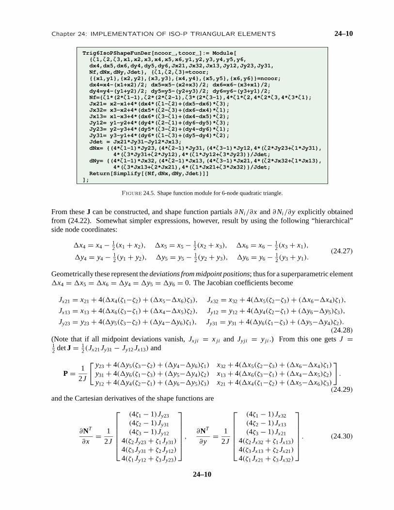
Figure 24.5. Shape function module for 6-node quadratic triangle.
From theseJ can be constructed, and shape function partials∂Ni /∂x and∂Ni /∂y explicitly obtainedfrom (24.22). Somewhat simpler expressions, however, result by using the following “hierarchical”side node coordinates:
�x4 = x4 − 12(x1 + x2), �x5 = x5 − 1
2(x2 + x3), �x6 = x6 − 12(x3 + x1),
�y4 = y4 − 12(y1 + y2), �y5 = y5 − 1
2(y2 + y3), �y6 = y6 − 12(y3 + y1).
(24.27)
Geometrically these represent thedeviations from midpoint positions; thus for a superparametric element�x4 = �x5 = �x6 = �y4 = �y5 = �y6 = 0. The Jacobian coefficients become
Jx21 = x21 + 4(�x4(ζ1−ζ2) + (�x5−�x6)ζ3), Jx32 = x32 + 4(�x5(ζ2−ζ3) + (�x6−�x4)ζ1),
Jx13 = x13 + 4(�x6(ζ3−ζ1) + (�x4−�x5)ζ2), Jy12 = y12 + 4(�y4(ζ2−ζ1) + (�y6−�y5)ζ3),
Jy23 = y23 + 4(�y5(ζ3−ζ2) + (�y4−�y6)ζ1), Jy31 = y31 + 4(�y6(ζ1−ζ3) + (�y5−�y4)ζ2).
(24.28)(Note that if all midpoint deviations vanish,Jx ji = xji and Jyji = yji .) From this one getsJ =12 detJ = 1
2(Jx21Jy31 − Jy12Jx13) and
P = 1
2J
[ y23 + 4(�y5(ζ3−ζ2) + (�y4−�y6)ζ1) x32 + 4(�x5(ζ2−ζ3) + (�x6−�x4)ζ1)
y31 + 4(�y6(ζ1−ζ3) + (�y5−�y4)ζ2) x13 + 4(�x6(ζ3−ζ1) + (�x4−�x5)ζ2)
y12 + 4(�y4(ζ2−ζ1) + (�y6−�y5)ζ3) x21 + 4(�x4(ζ1−ζ2) + (�x5−�x6)ζ3)
].
(24.29)and the Cartesian derivatives of the shape functions are
∂NT
∂x= 1
2J
(4ζ1 − 1)Jy23
(4ζ2 − 1)Jy31
(4ζ3 − 1)Jy12
4(ζ2Jy23 + ζ1Jy31)
4(ζ3Jy31 + ζ2Jy12)
4(ζ1Jy12 + ζ3Jy23)
,
∂NT
∂y= 1
2J
(4ζ1 − 1)Jx32
(4ζ2 − 1)Jx13
(4ζ3 − 1)Jx21
4(ζ2Jx32 + ζ1Jx13)
4(ζ3Jx13 + ζ2Jx21)
4(ζ1Jx21 + ζ3Jx32)
. (24.30)
24–10

24–11 §24.4 THE QUADRATIC TRIANGLE
Trig6IsoPMembraneStiffness[ncoor_,Emat_,th_,options_]:= Module[{i,k,p=3,numer=False,h=th,tcoor,w,c, Nf,dNx,dNy,Jdet,Be,Ke=Table[0,{12},{12}]}, If [Length[options]>=1, numer=options[[1]]]; If [Length[options]>=2, p= options[[2]]]; If [!MemberQ[{1,-3,3,6,7},p], Print["Illegal p"]; Return[Null]]; For [k=1, k<=Abs[p], k++, {tcoor,w}= TrigGaussRuleInfo[{p,numer},k]; {Nf,dNx,dNy,Jdet}= Trig6IsoPShapeFunDer[ncoor,tcoor]; If [numer, {Nf,dNx,dNy,Jdet}=N[{Nf,dNx,dNy,Jdet}]]; If [Length[th]==6, h=th.Nf]; c=w*Jdet*h/2; Be= {Flatten[Table[{dNx[[i]],0 },{i,6}]], Flatten[Table[{0, dNy[[i]]},{i,6}]], Flatten[Table[{dNy[[i]],dNx[[i]]},{i,6}]]}; Ke+=c*Transpose[Be].(Emat.Be); ]; If[!numer,Ke=Simplify[Ke]]; Return[Ke] ];
Figure 24.6. Stiffness matrix module for 6-node plane stress triangle.
A Mathematicashape function moduleTrig6IsoPShapeFunDer is shown in Figure 24.5. It receivestwo arguments:ncoor andtcoor. The first one is the list of{xi , yi } coordinates of the six nodes. Thesecond is the list of three triangular coordinates{ ζ1, ζ2, ζ3 } of the location at which the shape functionsand their Cartesian derivatives are to be computed.
The module returns{ Nf,dNx,dNy,Jdet } as module value. HereNf collects the shape function values,dNx anddNy thex andy shape function derivatives, respectively, andJdet is the determinant of matrixJ, equal to 2J in the notation used here.
§24.4.2. Stiffness Module
The numerically integrated stiffness matrix is
Ke =∫
e
hBT EB d ≈p∑
i =1
wi F(ζ1i , ζ2i , ζ3i ), where F(ζ1, ζ2, ζ3) = hBT EB J. (24.31)
Here p denotes the number of sample points of the Gauss rule being used,wi is the integration weightfor the i th sample point,ζ1i , ζ2i , ζ3i are the sample point triangular coordinates andJ = 1
2 detJ. Thisdata is provided byTrigGaussRuleInfo. For the 6-node triangle (24.31) is implemented in moduleTrig6IsoPMembraneStiffness, listed in Figure 24.6. The module is invoked as
Ke = Trig6IsoPMembraneStiffness[ncoor,Emat,th,options] (24.32)
The arguments are:
ncoor The list of node coordinates arranged as{ { x1,y1 },{ x2,y2 }, ... { x6,y6 } }.Emat The plane stress elasticity matrix
E =[ E11 E12 E13
E12 E22 E23E13 E23 E33
](24.33)
arranged as{ { E11,E12,E33 },{ E12,E22,E23 },{ E13,E23,E33 } }.th Plate thickness specified as either a scalarh or a six-entry list:{ h1,h2,h3,h4,h5,h6 }.
24–11

Chapter 24: IMPLEMENTATION OF ISO-P TRIANGULAR ELEMENTS 24–12
The one-entry form specifies uniform thicknessh. The six-entry form is used to specifyan element of variable thickness, in which case the entries are the six node thicknessesandh is interpolated quadratically.
options Processing options list. May contain two items:{ numer,rule } or one:{ numer }.numer is a logical flag. IfTrue, the computations are forced to proceed in floating-pointarithmetic. For symbolic or exact arithmetic work setnumer to False.
rule specifies the triangle Gauss rule as described in §24.2.4;rule may be 1, 3,−3, 6or 7. For the 6-node element the three point rules are sufficient to get the correct rank.If omittedrule = 3 is assumed.
The module returnsKe as an 12× 12 symmetric matrix pertaining to the following arrangement ofnodal displacements:
ue = [ ux1 uy1 ux2 uy2 ux3 uy3 ux4 uy4 ux5 uy5 ux6 uy6 ]T . (24.34)
§24.4.3. Test on Straight-Sided Triangle
The stiffness module of Figure 24.6 is tested on twotriangle geometries, one with straight sides and constantmetric and one with curved sides and highly variablemetric. The straight sided triangle geometry, shown inFigure 24.7, has the corner nodes placed at(0, 0), (6, 2)
and(4, 4) with side nodes 4,5,6 at the midpoints of thesides. The element has unit plate thickness. The materialis isotropic withE = 288 andν = 1/3.
The element is tested with the script shown in Figure24.8. The stiffness matrixKe is computed by the three-interior-point Gauss rule, specified asp=3.
1 (0,0)
2 (6,2)
3 (4,4)
4
5
6
Figure24.7. Straight sided 6-node triangletest element.
The computedKe for integration rules with 3 or more points are identical since those rules are exactfor this element if the metric is constant, which is the case here. That stiffness is
54 27 18 0 0 9 −72 0 0 0 0 −3627 54 0 −18 9 36 0 72 0 0 −36 −14418 0 216 −108 54 −36 −72 0 −216 144 0 00 −18 −108 216 −36 90 0 72 144 −360 0 00 9 54 −36 162 −81 0 0 −216 144 0 −369 36 −36 90 −81 378 0 0 144 −360 −36 −144
−72 0 −72 0 0 0 576 −216 0 −72 −432 2880 72 0 72 0 0 −216 864 −72 −288 288 −7200 0 −216 144 −216 144 0 −72 576 −216 −144 00 0 144 −360 144 −360 −72 −288 −216 864 0 1440 −36 0 0 0 −36 −432 288 −144 0 576 −216
−36 −144 0 0 −36 −144 288 −720 0 144 −216 864
(24.35)
The eigenvalues are:
[ 1971.66 1416.75 694.82 545.72 367.7 175.23 157.68 57.54 12.899 0 0 0] (24.36)
The 3 zero eigenvalues pertain to the three independent rigid-body modes. The 9 other ones are positive.Consequently the computedKe has the correct rank of 9.
24–12

24–13 §24.4 THE QUADRATIC TRIANGLE
ClearAll[Em,ν,a,b,e,h]; h=1; Em=288; ν=1/3;ncoor={{0,0},{6,2},{4,4},{3,1},{5,3},{2,2}};Emat=Em/(1-ν^2)*{{1,ν,0},{ν,1,0},{0,0,(1-ν)/2}};Print["Emat=",Emat//MatrixForm]Ke=Trig6IsoPMembraneStiffness[ncoor,Emat,h,{False,3}]; Ke=Simplify[Ke]; Print[Chop[Ke]//MatrixForm];Print["eigs of Ke=",Chop[Eigenvalues[N[Ke]]]];
Figure 24.8. Script to formKe of test triangle of Figure 24.7.
§24.4.4. Test on Highly Distorted Triangle
A highly distorted test geometry places the 3 cornersat the vertices of an equilateral triangle:{−1/2, 0},{1/2, 0}, {0,
√3/2} whereas the 3 side nodes are located
at {0, −1/(2√
3)}, {1/2, 1/√
3} and{−1/2, 1/√
3}. Theresult is that the six nodes lie on a circle of radius 1/
√3, as
depicted in Figure 24.9. The element has unit thickness.The material is isotropic withE = 504 andν = 0. ThestiffnessKe is evaluated for four the rank-sufficient rules:3,-3,6,7, using the script of Figure 24.10.
4 ( )
5 ( )6 ( )
1 (−1/2,0) 2 (1/2,0)
3 ( ) 0,√
3/2γ
√0, −1/(2 3)
1/2, 1/√
3√
−1/2, 1/ 3
Figure 24.9. Test curved sided quadratictriangle, with the 6 nodes lying on a circle.
ClearAll[Em,ν,h]; h=1; Em=7*72; ν=0; h=1;{x1,y1}={-1,0}/2; {x2,y2}={1,0}/2; {x3,y3}={0,Sqrt[3]}/2;{x4,y4}={0,-1/Sqrt[3]}/2; {x5,y5}={1/2,1/Sqrt[3]}; {x6,y6}={-1/2,1/Sqrt[3]};ncoor= {{x1,y1},{x2,y2},{x3,y3},{x4,y4},{x5,y5},{x6,y6}};Emat=Em/(1-ν^2)*{{1,ν,0},{ν,1,0},{0,0,(1-ν)/2}};For [i=2,i<=5,i++, p={1,-3,3,6,7}[[i]]; Ke=Trig6IsoPMembraneStiffness[ncoor,Emat,h,{True,p}]; Ke=Chop[Simplify[Ke]]; Print["Ke=",SetPrecision[Ke,4]//MatrixForm]; Print["Eigenvalues of Ke=",Chop[Eigenvalues[N[Ke]],.0000001]] ];
Figure 24.10. Script to formKe for the triangle of Figure 24.9, using four integration rules.
Forrule=3 the result (printed to 4 places because of theSetPrecision statement in script) is
344.7 75.00 −91.80 21.00 −86.60 −24.00 −124.7 −72.00 −20.78 −36.00 −20.78 36.0075.00 258.1 −21.00 −84.87 18.00 −90.07 96.00 0 −36.00 20.78 −132.0 −103.9
−91.80 −21.00 344.7 −75.00 −86.60 24.00 −124.7 72.00 −20.78 −36.00 −20.78 36.0021.00 −84.87 −75.00 258.1 −18.00 −90.07 −96.00 0 132.0 −103.9 36.00 20.78
−86.60 18.00 −86.60 −18.00 214.8 0 41.57 0 −41.57 144.0 −41.57 −144.0−24.00 −90.07 24.00 −90.07 0 388.0 0 −41.57 −24.00 −83.14 24.00 −83.14−124.7 96.00 −124.7 −96.00 41.57 0 374.1 0 −83.14 −72.00 −83.14 72.00−72.00 0 72.00 0 0 −41.57 0 374.1 −72.00 −166.3 72.00 −166.3−20.78 −36.00 −20.78 132.0 −41.57 −24.00 −83.14 −72.00 374.1 0 −207.8 0−36.00 20.78 −36.00 −103.9 144.0 −83.14 −72.00 −166.3 0 374.1 0 −41.57−20.78 −132.0 −20.78 36.00 −41.57 24.00 −83.14 72.00 −207.8 0 374.1 0
36.00 −103.9 36.00 20.78 −144.0 −83.14 72.00 −166.3 0 −41.57 0 374.1
(24.37)
24–13

Chapter 24: IMPLEMENTATION OF ISO-P TRIANGULAR ELEMENTS 24–14
Forrule=-3:
566.4 139.0 129.9 21.00 79.67 8.000 −364.9 −104.0 −205.5 −36.00 −205.5 −28.00139.0 405.9 −21.00 62.93 50.00 113.2 64.00 −129.3 −36.00 −164.0 −196.0 −288.7129.9 −21.00 566.4 −139.0 79.67 −8.000 −364.9 104.0 −205.5 28.00 −205.5 36.0021.00 62.93 −139.0 405.9 −50.00 113.2 −64.00 −129.3 196.0 −288.7 36.00 −164.079.67 50.00 79.67 −50.00 325.6 0 −143.2 0 −170.9 176.0 −170.9 −176.08.000 113.2 −8.000 113.2 0 646.6 0 −226.3 8.000 −323.3 −8.000 −323.3
−364.9 64.00 −364.9 −64.00 −143.2 0 632.8 0 120.1 −104.0 120.1 104.0−104.0 −129.3 104.0 −129.3 0 −226.3 0 485.0 −104.0 0 104.0 0−205.5 −36.00 −205.5 196.0 −170.9 8.000 120.1 −104.0 521.9 −64.00 −60.04 0−36.00 −164.0 28.00 −288.7 176.0 −323.3 −104.0 0 −64.00 595.8 0 180.1−205.5 −196.0 −205.5 36.00 −170.9 −8.000 120.1 104.0 −60.04 0 521.9 64.00−28.00 −288.7 36.00 −164.0 −176.0 −323.3 104.0 0 0 180.1 64.00 595.8
(24.38)The stiffness forrule=6 is omitted to save space. Forrule=7:
661.9 158.5 141.7 21.00 92.53 7.407 −432.1 −117.2 −190.2 −29.10 −273.8 −40.61158.5 478.8 −21.00 76.13 49.41 125.3 50.79 −182.7 −29.10 −156.6 −208.6 −341.0141.7 −21.00 661.9 −158.5 92.53 −7.407 −432.1 117.2 −273.8 40.61 −190.2 29.1021.00 76.13 −158.5 478.8 −49.41 125.3 −50.79 −182.7 208.6 −341.0 29.10 −156.692.53 49.41 92.53 −49.41 387.3 0 −139.8 0 −216.3 175.4 −216.3 −175.47.407 125.3 −7.407 125.3 0 753.4 0 −207.0 7.407 −398.5 −7.407 −398.5
−432.1 50.79 −432.1 −50.79 −139.8 0 723.6 0 140.2 −117.2 140.2 117.2−117.2 −182.7 117.2 −182.7 0 −207.0 0 562.6 −117.2 4.884 117.2 4.884−190.2 −29.10 −273.8 208.6 −216.3 7.407 140.2 −117.2 602.8 −69.71 −62.78 0−29.10 −156.6 40.61 −341.0 175.4 −398.5 −117.2 4.884 −69.71 683.3 0 207.9−273.8 −208.6 −190.2 29.10 −216.3 −7.407 140.2 117.2 −62.78 0 602.8 69.71−40.61 −341.0 29.10 −156.6 −175.4 −398.5 117.2 4.884 0 207.9 69.71 683.3
(24.39)The eigenvalues of these matrices are:
Rule Eigenvalues ofKe
3 702.83 665.11 553.472 553.472 481.89 429.721 429.721 118.391 118.391 0 0 0−3 1489.80 1489.80 702.833 665.108 523.866 523.866 481.890 196.429 196.429 0 0 0
6 1775.53 1775.53 896.833 768.948 533.970 533.970 495.570 321.181 321.181 0 0 07 1727.11 1727.11 880.958 760.719 532.750 532.750 494.987 312.123 312.123 0 0 0
(24.40)Since the metric of this element is very distorted near its boundary, the stiffness matrix entries and
eigenvalues change substantially as the integration formulas are advanced from 3 to 6 and 7 points.However as can be seen the matrix remains rank-sufficient.
§24.5. *The Cubic Triangle
The 10-node cubic triangle, depicted in Figure 24.11, is rarely used as such in applications because of the difficultyof combining it with other elements. Nevertheless the derivation of the element modules is instructive as thistriangle has other and more productive uses as a generator of more practical elements with “drilling” rotationaldegrees of freedom at corners for modeling shells. Such transformations are studied in advanced FEM courses.
The geometry of the triangle is defined by the coordinates of the ten nodes. A notational warning: the interior nodeis labeled as 0 instead of 10 (cf. Figure 24.8) to avoid confusion with notation such asx12 = x1 − x2 for coordinatedifferences.
24–14

24–15 §24.5 *THE CUBIC TRIANGLE
§24.5.1. *Shape Function Module
The shape functions obtained in Exercise 18.1 areN1 = 12ζ1(3ζ1 − 1)(3ζ1 − 2), N2 = 1
2ζ2(3ζ2 − 1)(3ζ2 − 2),N3 = 1
2ζ3(3ζ3−1)(3ζ3−2), N4 = 92ζ1ζ2(3ζ1−1), N5 = 9
2ζ1ζ2(3ζ2−1), N6 = 92ζ2ζ3(3ζ2−1), N7 = 9
2ζ2ζ3(3ζ3−1),N8 = 9
2ζ3ζ1(3ζ3 − 1), N9 = 92ζ3ζ1(3ζ1 − 1) andN0 = 27ζ1ζ2ζ3. Their natural derivatives are
∂NT
∂ζ1= 9
2
29−2ζ1+3ζ 2
100
ζ2(6ζ1−1)
ζ2(3ζ2−1)
00
ζ3(3ζ3−1)
ζ3(6ζ1−1)
6ζ2ζ3
,∂NT
∂ζ2= 9
2
029−2ζ2+3ζ 2
20
ζ1(3ζ1−1)
ζ1(6ζ2−1)
ζ3(6ζ2−1)
ζ3(3ζ3−1)
00
6ζ1ζ3
,∂NT
∂ζ3= 9
2
00
29−2ζ3+3ζ 2
300
ζ2(3ζ2−1)
ζ2(6ζ3−1)
ζ1(6ζ3−1)
ζ1(3ζ1−1)
6ζ1ζ2
. (24.41)
As in the case of the 6-node triangle it is convenient to introducethe deviations from thirdpoints and centroid:�x4 = x4 −13(2x1+x2), �x5 = x5 − 1
3(x1+2x2), �x6 = x6 − 13(2x2+x3),
�x7 = x7 − 13(x2+2x3), �x8 = x8 − 1
3(2x3+x1), �x9 = x9 −13(x3+2x1),�x0 = x0− 1
3(x1+x2+x3),�y4 = y4− 13(2y1+y2),
�y5 = y5 − 13(y1+2y2), �y6 = y6 − 1
3(2y2+y3), �y7 = y7 −13(y2+2y3), �y8 = y8 − 1
3(2y3+y1), �y9 = y9 − 13(y3+2y1),
and�y0 = y0 − 13(y1 + y2 + y3).
1
2
3
4 5
6
78
90
Figure 24.11. The 10-node cubic triangle.
Using (24.22) and (24.41), the shape function partial derivatives can be worked out to be
∂NT
∂x= 9
4J
Jy23(29 − 2ζ1 + 3ζ 2
1 /2)
Jy31(29 − 2ζ2 + 3ζ 2
2 /2)
Jy12(29 − 2ζ3 + 3ζ 2
3 /2)
Jy31ζ1(3ζ1 − 1) + Jy23ζ2(6ζ1 − 1)
Jy23ζ2(3ζ2 − 1) + Jy31ζ1(6ζ2 − 1)
Jy12ζ2(3ζ2 − 1) + Jy31ζ3(6ζ2 − 1)
Jy31ζ3(3ζ3 − 1) + Jy12ζ2(6ζ3 − 1)
Jy23ζ3(3ζ3 − 1) + Jy12ζ1(6ζ3 − 1)
Jy12ζ1(3ζ1 − 1) + Jy23ζ3(6ζ1 − 1)
6(Jy12ζ1ζ2 + Jy31ζ1ζ3 + Jy23ζ2ζ3)
,∂NT
∂y= 9
4J
Jx32(29 − 2ζ1 + 3ζ 2
1 /2)
Jx13(29 − 2ζ2 + 3ζ 2
2 /2)
Jx21(29 − 2ζ3 + 3ζ 2
3 /2)
Jx13ζ1(3ζ1 − 1) + Jx32ζ2(6ζ1 − 1)
Jx32ζ2(3ζ2 − 1) + Jx13ζ1(6ζ2 − 1)
Jx21ζ2(3ζ2 − 1) + Jx13ζ3(6ζ2 − 1)
Jx13ζ3(3ζ3 − 1) + Jx21ζ2(6ζ3 − 1)
Jx32ζ3(3ζ3 − 1) + Jx21ζ1(6ζ3 − 1)
Jx21ζ1(3ζ1 − 1) + Jx32ζ3(6ζ1 − 1)
6(Jx21ζ1ζ2 + Jx13ζ1ζ3 + Jx32ζ2ζ3)
.
(24.42)where the expressions of the Jacobian coefficients are
Jx21 = x21 + 92
[�x4
(ζ1(3ζ1−6ζ2−1)+ζ2
) + �x5
(ζ2(1−3ζ2+6ζ1)−ζ1
) + �x6ζ3(6ζ2−1)
+ �x7ζ3(3ζ3−1) + �x8ζ3(1−3ζ3) + �x9ζ3(1−6ζ1) + 6�x0ζ3(ζ1−ζ2)],
Jx32 = x32 + 92
[�x4ζ1(1−3ζ1) + �x5ζ1(1−6ζ2) + �x6
(ζ2(3ζ2−6ζ3−1)+ζ3
)+ �x7
(ζ3(1−3ζ3+6ζ2)−ζ2
) + �x8ζ1(6ζ3−1) + �x9ζ1(3ζ1−1) + 6�x0ζ1(ζ2−ζ3)],
Jx13 = x13 + 92
[�x4(6ζ1−1)ζ2 + �x5ζ2(3ζ2−1) + �x6ζ2(1−3ζ2) + �x7ζ2(1−6ζ3)
+ �x8
(ζ3(3ζ3−6ζ1−1)+ζ1
) + �x9
(ζ1(1−3ζ1+6ζ3)−ζ3
) + 6�x0ζ2(ζ3−ζ1)],
(24.43)
24–15

Chapter 24: IMPLEMENTATION OF ISO-P TRIANGULAR ELEMENTS 24–16
Trig10IsoPShapeFunDer[ncoor_,tcoor_]:= Module[ {ζ1,ζ2,ζ3,x1,x2,x3,x4,x5,x6,x7,x8,x9,x0,y1,y2,y3,y4,y5,y6,y7,y8,y9,y0, dx4,dx5,dx6,dx7,dx8,dx9,dx0,dy4,dy5,dy6,dy7,dy8,dy9,dy0, Jx21,Jx32,Jx13,Jy12,Jy23,Jy31,Nf,dNx,dNy,Jdet}, {{x1,y1},{x2,y2},{x3,y3},{x4,y4},{x5,y5},{x6,y6},{x7,y7}, {x8,y8},{x9,y9},{x0,y0}}=ncoor; {ζ1,ζ2,ζ3}=tcoor; dx4=x4-(2*x1+x2)/3; dx5=x5-(x1+2*x2)/3; dx6=x6-(2*x2+x3)/3; dx7=x7-(x2+2*x3)/3; dx8=x8-(2*x3+x1)/3; dx9=x9-(x3+2*x1)/3; dy4=y4-(2*y1+y2)/3; dy5=y5-(y1+2*y2)/3; dy6=y6-(2*y2+y3)/3; dy7=y7-(y2+2*y3)/3; dy8=y8-(2*y3+y1)/3; dy9=y9-(y3+2*y1)/3; dx0=x0-(x1+x2+x3)/3; dy0=y0-(y1+y2+y3)/3; Nf={ζ1*(3*ζ1-1)*(3*ζ1-2),ζ2*(3*ζ2-1)*(3*ζ2-2),ζ3*(3*ζ3-1)*(3*ζ3-2), 9*ζ1*ζ2*(3*ζ1-1),9*ζ1*ζ2*(3*ζ2-1),9*ζ2*ζ3*(3*ζ2-1), 9*ζ2*ζ3*(3*ζ3-1),9*ζ3*ζ1*(3*ζ3-1),9*ζ3*ζ1*(3*ζ1-1),54*ζ1*ζ2*ζ3}/2; Jx21=x2-x1+(9/2)*(dx4*(ζ1*(3*ζ1-6*ζ2-1)+ζ2)+ dx5*(ζ2*(1-3*ζ2+6*ζ1)-ζ1)+dx6*ζ3*(6*ζ2-1)+dx7*ζ3*(3*ζ3-1)+ dx8*ζ3*(1-3*ζ3)+dx9*ζ3*(1-6*ζ1)+6*dx0*ζ3*(ζ1-ζ2)); Jx32=x3-x2+(9/2)*(dx4*ζ1*(1-3*ζ1)+dx5*ζ1*(1-6*ζ2)+ dx6*(ζ2*(3*ζ2-6*ζ3-1)+ζ3)+dx7*(ζ3*(1-3*ζ3+6*ζ2)-ζ2)+ dx8*ζ1*(6*ζ3-1)+dx9*ζ1*(3*ζ1-1)+6*dx0*ζ1*(ζ2-ζ3)) ; Jx13=x1-x3+(9/2)*(dx4*(6*ζ1-1)*ζ2+dx5*ζ2*(3*ζ2-1)+ dx6*ζ2*(1-3*ζ2)+dx7*ζ2*(1-6*ζ3)+dx8*(ζ3*(3*ζ3-6*ζ1-1)+ζ1)+ dx9*(ζ1*(1-3*ζ1+6*ζ3)-ζ3)+6*dx0*ζ2*(ζ3-ζ1)); Jy12=y1-y2-(9/2)*(dy4*(ζ1*(3*ζ1-6*ζ2-1)+ζ2)+ dy5*(ζ2*(1-3*ζ2+6*ζ1)-ζ1)+dy6*ζ3*(6*ζ2-1)+dy7*ζ3*(3*ζ3-1)+ dy8*ζ3*(1-3*ζ3)+dy9*ζ3*(1-6*ζ1)+6*dy0*ζ3*(ζ1-ζ2)); Jy23=y2-y3-(9/2)*(dy4*ζ1*(1-3*ζ1)+dy5*ζ1*(1-6*ζ2)+ dy6*(ζ2*(3*ζ2-6*ζ3-1)+ζ3)+dy7*(ζ3*(1-3*ζ3+6*ζ2)-ζ2)+ dy8*ζ1*(6*ζ3-1)+dy9*ζ1*(3*ζ1-1)+6*dy0*ζ1*(ζ2-ζ3)) ; Jy31=y3-y1-(9/2)*(dy4*(6*ζ1-1)*ζ2+dy5*ζ2*(3*ζ2-1)+ dy6*ζ2*(1-3*ζ2)+dy7*ζ2*(1-6*ζ3)+dy8*(ζ3*(3*ζ3-6*ζ1-1)+ζ1)+ dy9*(ζ1*(1-3*ζ1+6*ζ3)-ζ3)+6*dy0*ζ2*(ζ3-ζ1)); Jdet = Jx21*Jy31-Jy12*Jx13; dNx={Jy23*(2/9-2*ζ1+3*ζ1^2),Jy31*(2/9-2*ζ2+3*ζ2^2),Jy12*(2/9-2*ζ3+3*ζ3^2), Jy31*ζ1*(3*ζ1-1)+Jy23*ζ2*(6*ζ1-1),Jy23*ζ2*(3*ζ2-1)+Jy31*ζ1*(6*ζ2-1), Jy12*ζ2*(3*ζ2-1)+Jy31*ζ3*(6*ζ2-1),Jy31*ζ3*(3*ζ3-1)+Jy12*ζ2*(6*ζ3-1), Jy23*ζ3*(3*ζ3-1)+Jy12*ζ1*(6*ζ3-1),Jy12*ζ1*(3*ζ1-1)+Jy23*ζ3*(6*ζ1-1), 6*(Jy12*ζ1*ζ2+Jy31*ζ1*ζ3+Jy23*ζ2*ζ3)}/(2*Jdet/9); dNy={Jx32*(2/9-2*ζ1+3*ζ1^2),Jx13*(2/9-2*ζ2+3*ζ2^2),Jx21*(2/9-2*ζ3+3*ζ3^2), Jx13*ζ1*(3*ζ1-1)+Jx32*ζ2*(6*ζ1-1),Jx32*ζ2*(3*ζ2-1)+Jx13*ζ1*(6*ζ2-1), Jx21*ζ2*(3*ζ2-1)+Jx13*ζ3*(6*ζ2-1),Jx13*ζ3*(3*ζ3-1)+Jx21*ζ2*(6*ζ3-1), Jx32*ζ3*(3*ζ3-1)+Jx21*ζ1*(6*ζ3-1),Jx21*ζ1*(3*ζ1-1)+Jx32*ζ3*(6*ζ1-1), 6*(Jx21*ζ1*ζ2+Jx13*ζ1*ζ3+Jx32*ζ2*ζ3)}/(2*Jdet/9); Return[Simplify[{Nf,dNx,dNy,Jdet}]]];
Figure 24.12. Shape function module for 10-node cubic triangle.
and
Jy12 = y12 − 92
[�y4
(ζ1(3ζ1−6ζ2−1)+ζ2
) + �y5(ζ2(1−3ζ2+6ζ1)−ζ1) + �y6ζ3(6ζ2−1)
+ �y7ζ3(3ζ3−1) + �y8ζ3(1−3ζ3) + �y9ζ3(1−6ζ1) + 6�y0ζ3(ζ1−ζ2)],
Jy23 = y23 − 92
[�y4ζ1(1−3ζ1) + �y5ζ1(1−6ζ2) + �y6
(ζ2(3ζ2−6ζ3−1)+ζ3
)+ �y7
(ζ3(1−3ζ3+6ζ2)−ζ2
) + �y8ζ1(6ζ3−1) + �y9ζ1(3ζ1−1) + 6�y0ζ1(ζ2−ζ3)],
Jy31 = y31 − 92
[�y4(6ζ1−1)ζ2 + �y5ζ2(3ζ2−1) + �y6ζ2(1−3ζ2) + �y7ζ2(1−6ζ3)
+ �y8
(ζ3(3ζ3−6ζ1−1)+ζ1
) + �y9
(ζ1(1−3ζ1+6ζ3)−ζ3
) + 6�y0ζ2(ζ3−ζ1)].
(24.44)
The Jacobian determinant isJ = 12(Jx21Jy31 − Jy12Jx13). The shape function moduleTrig10IsoPShapeFunDer
that implements these expressions is listed in Figure24.12. Thishas the sameargumentsasTrig6IsoPShapeFunDer.As thereJdet denotes 2J.
24–16

24–17 §24.5 *THE CUBIC TRIANGLE
Trig10IsoPMembraneStiffness[ncoor_,Emat_,th_,options_]:= Module[{i,k,l,p=6,numer=False,h=th,tcoor,w,c, Nf,dNx,dNy,Jdet,Be,Ke=Table[0,{20},{20}]}, If [Length[options]>=1, numer=options[[1]]]; If [Length[options]>=2, p= options[[2]]]; If [!MemberQ[{1,3,-3,6,7},p], Print["Illegal p"]; Return[Null]]; For [k=1, k<=Abs[p], k++, {tcoor,w}= TrigGaussRuleInfo[{p,numer},k]; {Nf,dNx,dNy,Jdet}= Trig10IsoPShapeFunDer[ncoor,tcoor]; If [numer, {Nf,dNx,dNy,Jdet}=N[{Nf,dNx,dNy,Jdet}]]; If [Length[th]==10, h=th.Nf]; c=w*Jdet*h/2; Be= {Flatten[Table[{dNx[[i]],0 },{i,10}]], Flatten[Table[{0, dNy[[i]]},{i,10}]], Flatten[Table[{dNy[[i]],dNx[[i]]},{i,10}]]}; Ke+=c*Transpose[Be].(Emat.Be); ]; If[!numer,Ke=Simplify[Ke]]; Return[Ke] ];
Figure 24.13. Stiffness module for 10-node cubic triangle.
§24.5.2. *Stiffness Module
Module Trig10IsoPMembraneStiffness, listed in Figure 24.13, implements the computation of the elementstiffness matrix of the 10-node cubic plane stress triangle. The module is invoked as
Ke = Trig10IsoPMembraneStiffness[ncoor,Emat,th,options] (24.45)
this has the same arguments of the quadratic triangle module invoked in (24.32), with the following changes. Thenode coordinate listncoor contains 10 entries:{ { x1,y1 },{ x2,y2 },{ x3,y3 }, . . .,{ x9,y9 },{ x0,y0 } }. If theplate thickness varies,th is a list of 10 entries:{ h1,h2,h3,h4,. . .,h9,h0 }. The triangle Gauss rule specified inoptions as{ numer,rule } should be 6 or 7 to produce a rank sufficient stiffness. If omittedrule = 6 is assumed.
The module returnsKe as an 20× 20 symmetric matrix pertaining to the following arrangement of nodal displace-ments:
ue = [ ux1 uy1 ux2 uy2 ux3 uy3 ux4 uy4 . . . ux9 uy9 ux0 uy0 ]T . (24.46)
Remark 24.3. For symbolic work with this element the 7-point rule should be preferred because the exactexpressions of the abcissas and weigths at sample points are simpler than for the 6-point rule, as can be observedin Figure 24.3. This speeds up algebraic simplification. For numerical work the 6-point rule is slightly faster.
§24.5.3. *Test Element
The stiffness module is tested on the superparametric trianglegeometry shown in Figure 24.14, which has been alreadyused for the quadratic triangle.
The corner nodes are placed at(0, 0), (6, 2) and(4, 4). The6 side nodes are located at the thirdpoints of the sides and theinterior node at the centroid. The plate has unit thickness.The material is isotropic withE = 1920 andν = 0.
The script of Figure 24.15 computesKe using the 7-pointGauss rule and exact arithmetic.
1 (0,0)
2 (6,2)
3 (4,4)
4
5
7
9
8 6
0
Figure 24.14. Test 10-node triangle.
The returned stiffness matrix using either 6- or 7-point integration is the same, since for a superparametric elementthe integrand is quartic in the triangular coordinates. For the given combination of inputs the entries are exactintegers:
24–17

Chapter 24: IMPLEMENTATION OF ISO-P TRIANGULAR ELEMENTS 24–18
Ke =
306 102 −42 −42 −21 21 −315 −333 171 153102 306 42 42 −63 −105 351 369 −135 −117−42 42 1224 −408 −210 42 252 −180 −234 306−42 42 −408 1224 126 −294 108 −36 −378 450−21 −63 −210 126 1122 −306 −99 27 −99 27
21 −105 42 −294 −306 1938 27 −171 27 −171−315 351 252 108 −99 27 5265 −1215 −1539 −243−333 369 −180 −36 27 −171 −1215 6885 729 −891
171 −135 −234 −378 −99 27 −1539 729 5265 −1215153 −117 306 450 27 −171 −243 −891 −1215 6885−27 −9 −1602 990 819 −171 81 81 −405 −405−9 −27 306 −2286 −459 1179 81 405 −405 −2025
−27 −9 828 −468 −1611 315 81 81 81 81−9 −27 −180 1116 999 −2223 81 405 81 40599 225 −108 36 −72 144 810 −324 810 −324
−63 387 36 −108 −540 −684 −324 1134 −324 1134−144 −504 −108 36 171 −99 −4050 1620 810 −324
180 −828 36 −108 189 531 1620 −5670 −324 11340 0 0 0 0 0 −486 −486 −4860 19440 0 0 0 0 0 −486 −2430 1944 −6804
−27 −9 −27 −9 99 −63 −144 180 0 0−9 −27 −9 −27 225 387 −504 −828 0 0
−1602 306 828 −180 −108 36 −108 36 0 0990 −2286 −468 1116 36 −108 36 −108 0 0819 −459 −1611 999 −72 −540 171 189 0 0
−171 1179 315 −2223 144 −684 −99 531 0 081 81 81 81 810 −324 −4050 1620 −486 −48681 405 81 405 −324 1134 1620 −5670 −486 −2430
−405 −405 81 81 810 −324 810 −324 −4860 1944−405 −2025 81 405 −324 1134 −324 1134 1944 −68045265 −1215 −3483 729 162 0 162 0 −972 0
−1215 6885 1701 −4779 0 −162 0 −162 0 972−3483 1701 5265 −1215 −810 0 162 0 −486 −486
729 −4779 −1215 6885 0 810 0 −162 −486 −2430162 0 −810 0 5265 −1215 −1296 −486 −4860 1944
0 −162 0 810 −1215 6885 486 −2592 1944 −6804162 0 162 0 −1296 486 5265 −1215 −972 0
0 −162 0 −162 −486 −2592 −1215 6885 0 972−972 0 −486 −486 −4860 1944 −972 0 12636 −2916
0 972 −486 −2430 1944 −6804 0 972 −2916 16524
(24.47)
The eigenvalues are
[ 26397. 16597. 14937. 12285. 8900.7 7626.2 5417.8 4088.8 3466.8 3046.4
1751.3 1721.4 797.70 551.82 313.22 254.00 28.019 0 0 0](24.48)
The 3 zero eigenvalues pertain to the three independent rigid-body modes in two dimensions. The 17 othereigenvalues are positive. Consequently the computedKe has the correct rank of 17.
24–18

24–19 §24. References
ClearAll[Em,Ν,a,b,e,h]; Em=1920; Ν=0; h=1; ncoor={{0,0},{6,2},{4,4}};x4=(2*x1+x2)/3; x5=(x1+2*x2)/3; y4=(2*y1+y2)/3; y5=(y1+2*y2)/3;x6=(2*x2+x3)/3; x7=(x2+2*x3)/3; y6=(2*y2+y3)/3; y7=(y2+2*y3)/3;x8=(2*x3+x1)/3; x9=(x3+2*x1)/3; y8=(2*y3+y1)/3; y9=(y3+2*y1)/3;x0=(x1+x2+x3)/3; y0=(y1+y2+y3)/3;ncoor= {{x1,y1},{x2,y2},{x3,y3},{x4,y4},{x5,y5},{x6,y6},{x7,y7}, {x8,y8},{x9,y9},{x0,y0}};Emat=Em/(1-Ν^2)*{{1,Ν,0},{Ν,1,0},{0,0,(1-Ν)/2}};Ke=Trig10IsoPMembraneStiffness[ncoor,Emat,h,{False,7}]; Ke=Simplify[Ke]; Print[Ke//MatrixForm]; ev=Chop[Eigenvalues[N[Ke]]];Print["eigs of Ke=",ev];
Figure 24.15. Script for testing cubic triangle of Figure 24.14.
Notes and Bibliography
The 3-node, 6-node and 10-node plane stress triangular elements are generated by complete polynomials in two-dimensions. In order of historical appearance:
1. The three-node linear triangle, also known asConstant Strain Triangle(CST) and Turner triangle, wasdeveloped as “triangular skin panel” by Turner, Clough and Martin in 1951–53 [31,32] using interelementflux assumptions, and published in 1956 [164]. It is not clear when the assumed-displacement derivation,which yields the same stiffness matrix, was done first. The displacement derivation is mentioned in passingby Clough in [25] and worked out in the theses of Melosh [114] and Wilson [177].
2. The six-node quadratic triangle, also known asLinear Strain Triangle(LST) and Veubeke triangle, wasdeveloped by B. M. Fraeijs de Veubeke in 1962–63 [186]; published 1965 [66].
3. The ten-node cubic triangle, also known asQuadratic Strain Triangle(QST), was developed by the writerin 1965; published 1966 [44]. Shape functions for the cubic triangle were presented there but used for platebending instead of plane stress.
A version of the cubic triangle with freedoms migrated to corners and recombined to produce a “drilling rotation”at corners, was used in static and dynamic shell analysis in Carr’s thesis under Ray Clough [23,28]. The drilling-freedom idea was independently exploited for rectangular and quadrilateral elements, respectively, in the theses ofAbu-Ghazaleh [2] and Willam [176], both under Alex Scordelis. A variant of the Willam quadrilateral, developedby Bo Almroth at Lockheed, has survived in the nonlinear shell analysis code STAGS as element 410 [137].
Numerical integration came into FEM by the mid 1960s. Five triangle integration rules were tabulated in the writer’sthesis [44, pp. 38–39]. These were gathered from three sources: two papers by Hammer and Stroud [84,85] andthe 1964 Handbook of Mathematical Functions [1, §25.4]. They were adapted to FEM by converting Cartesianabscissas to triangle coordinates. The table has been reproduced in Zienkiewicz’ book since the second edition[184, Table 8.2] and, with corrections and additions, in the monograph of Strang and Fix [149, p. 184].
The monograph by Stroud [152] contains a comprehensive collection of quadrature formulas for multi-ple integrals. That book gathers most of the formulas known by 1970, as well as references until thatyear. (Only a small fraction of Stroud’s tabulated rules, however, are suitable for FEM work.) The col-lection has been periodically kept up to date by Cools [34–36], who also maintains a dedicated web site:http://www.cs.kuleuven.ac.be/~nines/research/ecf/ecf.html This site provides rule information in16- and 32-digit accuracy for many geometries and dimensionalities as well as a linked “index card” of referencesto source publications.
References
Referenced items moved to Appendix R.
24–19

Chapter 24: IMPLEMENTATION OF ISO-P TRIANGULAR ELEMENTS 24–20
Homework Exercises for Chapter 24Implementation of Iso-P Triangular Elements
EXERCISE 24.1 [C:20] Write an element stiffness module and a shapefunction module for the 4-node “transition” iso-P triangular element withonly one side node: 4, which is located between 1 and 2. See Figure E24.1.The shape functions areN1 = ζ1 − 2ζ1ζ2, N2 = ζ2 − 2ζ1ζ2, N3 = ζ3 andN4 = 4ζ1ζ2. Use the three interior point integrationrule=3.
Test the element for the geometry of the triangle depicted in Figure 24.7,removing nodes 5 and 6, and withE = 2880, ν = 1/3 andh = 1.Report results for the stiffness matrixKe and its 8 eigenvalues. Note:NotebookTrig6Stiffness.nb for the 6-node triangle, posted on theindex of Chapter 24, may be used as “template” in support of this Exercise.Partial results:K11 = 1980,K18 = 1440.
1
42
3
Figure E24.1. The 4-node transi-tion triangle for Exercise 24.1.
EXERCISE 24.2 [A/C:5+20] As in the foregoing Exercise, but now write the module for a five-node triangular“transition” element that lacks midnode 6 opposite corner 2. Begin by deriving the five shape functions.
EXERCISE 24.3 [A+C:25] Consider the superparametric straight-sided 6-node triangle where side nodes arelocated at the midpoints. By settingx4 = 1
2(x1 + x2), x5 = 12(x2 + x3), x3 = 1
2(x3 + x1), y4 = 12(y1 + y2),
y5 = 12(y2 + y3), y3 = 1
2(y3 + y1) in (24.26), deduce that
J =[
1 1 13x1 2x1 + x2 2x1 + x3
3y1 2y1 + y2 2y1 + y3
]ζ1 +
[1 1 1
x1 + 2x2 3x2 2x2 + x3
y1 + 2y2 3y2 2y2 + y3
]ζ2 +
[1 1 1
x1 + 2x3 x2 + 2x3 3x3
y1 + 2y3 y2 + 2y3 3y3
]ζ3. (E24.1)
This contradicts publications that, by mistakingly assuming that the results for the linear triangle (Chapter 15) canbe extended by analogy, take
J =[
1 1 1x1 x2 x3
y1 y2 y3
](E24.2)
Show, however, that
2J = 2A = detJ = x3y12 + x1y23 + x2y31, P = 1
2J
[y23 y32
y31 x13
y12 x21
](E24.3)
are the same for both (E24.1) and (E24.2). Thus the mistake has no effect on the computation of derivatives.
EXERCISE 24.4 [A/C:15+15] Consider the superparametric straight-sided 6-node triangle where side nodes areat the midpoints of the sides and the thicknessh is constant. Using the 3-midpoint quadrature rule show that theelement stiffness can be expressed in a closed form obtained in 1966 [44]:
Ke = 13 Ah
(BT
1 EB1 + BT2 EB2 + BT
3 EB3
)(E24.4)
in which A is the triangle area and
B1 = 1
2A
[y32 0 y31 0 y12 0 2y23 0 2y32 0 2y23 00 x23 0 x13 0 x21 0 2x32 0 2x23 0 2x32
x23 y32 x13 y31 x21 y12 2x32 2y23 2x23 2y32 2x32 2y23
]
B2 = 1
2A
[y23 0 y13 0 y12 0 2y31 0 2y31 0 2y13 00 x32 0 x31 0 x21 0 2x13 0 2x13 0 2x31
x32 y23 x31 y13 x21 y12 2x13 2y31 2x13 2y31 2x31 2y13
]
B3 = 1
2A
[y23 0 y31 0 y21 0 2y21 0 2y12 0 2y12 00 x32 0 x13 0 x12 0 2x12 0 2x21 0 2x21
x32 y23 x13 y31 x12 y21 2x12 2y21 2x21 2y12 2x21 2y12
](E24.5)
24–20

24–21 §24. References
With this formKe can be computed in approximately 1000 floating-point operations.
Using next the 3-interior-point quadrature rule, show that the element stiffness can be expressed again as (E24.4)but with
B1 = 1
6A
[5y23 0 y13 0 y21 0 2y21 + 6y31 0 2y32 0 6y12 + 2y13 0
0 5x32 0 x31 0 x12 0 2x12 + 6x13 0 2x23 0 6x21 + 2x31
5x32 5y23 x31 y13 x12 y21 2x12 + 6x13 2y21 + 6y31 2x23 2y32 6x21 + 2x31 6y12 + 2y13
]
B2 = 1
6A
[y32 0 5y31 0 y21 0 2y21 + 6y23 0 6y12 + 2y32 0 2y13 00 x23 0 5x13 0 x12 0 2x12 + 6x32 0 6x21 + 2x23 0 2x31
x23 y32 5x13 5y31 x12 y21 2x12 + 6x32 2y21 + 6y23 6x21 + 2x23 6y12 + 2y32 2x31 2y13
]
B3 = 1
6A
[y32 0 y13 0 5y12 0 2y21 0 6y31 + 2y32 0 2y13 + 6y23 00 x23 0 x31 0 5x21 0 2x12 0 6x13 + 2x23 0 2x31 + 6x32
x23 y32 x31 y13 5x21 5y12 2x12 2y21 6x13 + 2x23 6y31 + 2y32 2x31 + 6x32 2y13 + 6y23
](E24.6)
The fact that two very different expressions yield the sameKe explains why sometimes authors rediscover the sameelement derived with different methods.
Yet another set that produces the correct stiffness is
B1 = 1
6A
[y23 0 y31 0 y21 0 2y21 0 2y12 0 2y12 00 x32 0 x13 0 x12 0 2x12 0 2x21 0 2x21
x32 y23 x13 y31 x12 y21 2x12 2y21 2x21 2y12 2x21 2y12
]
B2 = 1
6A
[y32 0 y31 0 y12 0 2y23 0 2y32 0 2y23 00 x23 0 x13 0 x21 0 2x32 0 2x23 0 2x32
x23 y32 x13 y31 x21 y12 2x32 2y23 2x23 2y32 2x32 2y23
]
B3 = 1
6A
[y23 0 y13 0 y12 0 2y31 0 2y31 0 2y13 00 x32 0 x31 0 x21 0 2x13 0 2x13 0 2x31
x32 y23 x31 y13 x21 y12 2x13 2y31 2x13 2y31 2x31 2y13
](E24.7)
EXERCISE 24.5 [A/C:40] (Research paper level) Characterize the most general form of theBi (i = 1, 2, 3)matrices that produce the same stiffness matrixKe in (E24.4). (Entails solving an algebraic Riccati equation.)
EXERCISE 24.6 [A/C:25]. Derive the 4-node transition triangle by forming the 6-node stiffness and applyingMFCs to eliminate 5 and 6. Prove that this technique only works if sides 1–3 and 2–3 are straight with nodes 5 and6 initially at the midpoint of those sides.
24–21