Implementation of Dynamic Voltage Restorer in · PDF fileInternational Journal of Science and...
6
International Journal of Science and Research (IJSR) ISSN (Online): 2319-7064 Index Copernicus Value (2013): 6.14 | Impact Factor (2013): 4.438 Volume 4 Issue 5, May 2015 www.ijsr.net Licensed Under Creative Commons Attribution CC BY Implementation of Dynamic Voltage Restorer in Distribution System Dhivya. T 1 SRM University, Master of Technology in Power Systems, Department of Electrical and Electronics Engineering, Kattankulathur Campus, Potheri- 603203 Abstract: Power quality is one of the major concerns in the era of power system. Power quality problem occurred due to non- standard voltage, current or frequency, that result in a failure of end user equipment. To overcome this problem, Dynamic Voltage Restorer (DVR) is used, which eliminate voltage sag, swell and during fault in the distribution line, it is efficient and effective power electronic device. The size of DVR is small, cost is low and fast dynamic response to the disturbance. By injecting an appropriate voltage, the DVR restores a voltage waveform and ensures constant load voltage. The compensating signals are determined dynamically based on the difference between desired and measured values. The DVR is consisting of VSC, Booster transformer, Filter and Energy storage devices. This paper used for compensate the voltage sag, voltage swell and during three phase fault of the distribution line. Keywords: Dynamic Voltage Restorer, Voltage source inverter, PI controller. 1. Introduction Modern power system is complex power network, where hundreds of generating loads and thousands of loads are interconnected through transmission or distribution networks. The main concern to the customer is to provide reliable and quality of power supply. But in develop country, the generation of power supply is fairly reliable, quality of power may poor. The ideal power supply system provides their customer uninterrupted flow of energy with smooth sinusoidal voltage at contracted voltage magnitude and frequency[1]. The power quality problem occurred due to the voltage sag, surge, flicker, voltage imbalance, interruption and harmonic problem. And it may cause problem to the industries from malfunctioning of equipment to the complete shutdown of the plant. Voltage sag/swell occurs as a result of load switching, motor starting, faults, non-linear loads, Lightning etc. It has major impact on microprocessor based loads as well as the sensitive loads. A new control strategy has been developed for achieving maximum benefits by eliminating or mitigating voltage sag / swell and power quality problem when abnormal condition occur in the distribution system, for this purpose the dynamic voltage restorer is proposed to improve the power quality and to reduce the sag and swell and during fault problem in the system, all objectives can be accomplished either individually or simultaneously. The DVR could be utilized as: Power converter to inject power at the time of fault in the system from DC source to the Grid. Compensating voltage unbalance, sags, and load reactive power demand. A supplier of the voltage at the time of heavily loaded conditions (with permissible limit). When system is lightly loaded, DVR can store the power or capacitor can be charges through it, which is utilize at the time of abnormal condition. As a very less cost effective device for improving the quality of power in distribution system comparatively other methods 1.1 Objectives of thesis The various objectives formulated and positioned for observation in the thesis are: 1) To study and analyze the complete distribution system and their problem. 2) To develop a mathematical model of various components DVR System, Voltage Sag, Three-Phase Inverter with Output. 3) To examine and analysis proposed model with and without Dynamic Voltage Restorer (DVR) system using MATLAB / SIMULINK. 4) To study the condition of developed DVR system for different case like voltage sag, swell, during fault and clearing fault. 1.2 Custom Power Device A safe, reliable and clean power supply to industries is a pre- requisite for their profitable operation and industrial activities. The concept of custom power supply has been proposed using advanced power electronics equipment to ensure a high quality of power supply and which could better mitigate the problems associated with power quality. Custom power technology is a general term for the equipments which are capable to mitigate numerous power quality problems including voltage sags[2]. The basic three customer power applications are as follows: Switching the load to another supply Injected missing voltage from an energy storage Injected missing voltage by increasing the line current (booster) Basic functions of customer power applications are fast switching and current or voltage injection for correcting anomalies in supply voltage or load current. Injecting or absorbing both active and reactive power is possible in these Paper ID: SUB154094 630
Transcript of Implementation of Dynamic Voltage Restorer in · PDF fileInternational Journal of Science and...

International Journal of Science and Research (IJSR) ISSN (Online): 2319-7064
Index Copernicus Value (2013): 6.14 | Impact Factor (2013): 4.438
Volume 4 Issue 5, May 2015
www.ijsr.net Licensed Under Creative Commons Attribution CC BY
Implementation of Dynamic Voltage Restorer in
Distribution System
Dhivya. T1
SRM University, Master of Technology in Power Systems, Department of Electrical and Electronics Engineering,
Kattankulathur Campus, Potheri- 603203
Abstract: Power quality is one of the major concerns in the era of power system. Power quality problem occurred due to non- standard
voltage, current or frequency, that result in a failure of end user equipment. To overcome this problem, Dynamic Voltage Restorer
(DVR) is used, which eliminate voltage sag, swell and during fault in the distribution line, it is efficient and effective power electronic
device. The size of DVR is small, cost is low and fast dynamic response to the disturbance. By injecting an appropriate voltage, the DVR
restores a voltage waveform and ensures constant load voltage. The compensating signals are determined dynamically based on the
difference between desired and measured values. The DVR is consisting of VSC, Booster transformer, Filter and Energy storage
devices. This paper used for compensate the voltage sag, voltage swell and during three phase fault of the distribution line.
Keywords: Dynamic Voltage Restorer, Voltage source inverter, PI controller.
1. Introduction
Modern power system is complex power network, where
hundreds of generating loads and thousands of loads are
interconnected through transmission or distribution networks.
The main concern to the customer is to provide reliable and
quality of power supply. But in develop country, the
generation of power supply is fairly reliable, quality of power
may poor. The ideal power supply system provides their
customer uninterrupted flow of energy with smooth
sinusoidal voltage at contracted voltage magnitude and
frequency[1]. The power quality problem occurred due to the
voltage sag, surge, flicker, voltage imbalance, interruption
and harmonic problem. And it may cause problem to the
industries from malfunctioning of equipment to the complete
shutdown of the plant. Voltage sag/swell occurs as a result of
load switching, motor starting, faults, non-linear loads,
Lightning etc. It has major impact on microprocessor based
loads as well as the sensitive loads.
A new control strategy has been developed for achieving
maximum benefits by eliminating or mitigating voltage sag /
swell and power quality problem when abnormal condition
occur in the distribution system, for this purpose the dynamic
voltage restorer is proposed to improve the power quality and
to reduce the sag and swell and during fault problem in the
system, all objectives can be accomplished either
individually or simultaneously.
The DVR could be utilized as:
Power converter to inject power at the time of fault in the
system from DC source to the Grid.
Compensating voltage unbalance, sags, and load reactive
power demand.
A supplier of the voltage at the time of heavily loaded
conditions (with permissible limit).
When system is lightly loaded, DVR can store the power
or capacitor can be charges through it, which is utilize at
the time of abnormal condition.
As a very less cost effective device for improving the quality
of power in distribution system comparatively other methods
1.1 Objectives of thesis
The various objectives formulated and positioned for
observation in the thesis are:
1) To study and analyze the complete distribution system and
their problem.
2) To develop a mathematical model of various components
DVR System, Voltage Sag, Three-Phase Inverter with
Output.
3) To examine and analysis proposed model with and without
Dynamic Voltage Restorer (DVR) system using MATLAB
/ SIMULINK.
4) To study the condition of developed DVR system for
different case like voltage sag, swell, during fault and
clearing fault.
1.2 Custom Power Device
A safe, reliable and clean power supply to industries is a pre-
requisite for their profitable operation and industrial
activities. The concept of custom power supply has been
proposed using advanced power electronics equipment to
ensure a high quality of power supply and which could better
mitigate the problems associated with power quality. Custom
power technology is a general term for the equipments which
are capable to mitigate numerous power quality problems
including voltage sags[2]. The basic three customer power
applications are as follows:
Switching the load to another supply
Injected missing voltage from an energy storage
Injected missing voltage by increasing the line current
(booster)
Basic functions of customer power applications are fast
switching and current or voltage injection for correcting
anomalies in supply voltage or load current. Injecting or
absorbing both active and reactive power is possible in these
Paper ID: SUB154094 630

International Journal of Science and Research (IJSR) ISSN (Online): 2319-7064
Index Copernicus Value (2013): 6.14 | Impact Factor (2013): 4.438
Volume 4 Issue 5, May 2015
www.ijsr.net Licensed Under Creative Commons Attribution CC BY
applications. Current injection is typically used for protecting
the power system from a polluting load.
Dynamic Voltage Restorer, with its excellent dynamic
capabilities, when installed between the supply and a critical
load feeder, can compensate for voltage sags, restoring line
voltage to its nominal value within a few milliseconds and
hence avoiding any power disruption to that load. This
device employs solid-state power electronic switches in a
pulse-width modulated (PWM) inverter structure[3].
The DVR functions by injecting three single phase AC
voltages in series with the three phase incoming network
voltages during a dip, compensating the difference between
faulty and nominal voltages. All three phases of the injected
voltages are of controllable amplitude and phase. Voltage
source inverter fed from the DC link supply the required
active and reactive power.
1.3 Propitious choice of DVR
There are numerous reasons why DVR is preferred over
other devices:
1) Although, SVC predominates the DVR but the latter is still
preferred because the SVC has no ability to control active
power flow.
2) DVR is less expensive compared to the UPS.
3) UPS also needs high level of maintenance because it has
problem of battery leak and have to be replace as often as
five years.
4) DVR has a relatively higher energy capacity and costs less
compared to SMES device.
5) DVR is smaller in size and costs less compared to
DSTATCOM
6) DVR is power efficient device compared to the UPS.
2. Design and Operation of DVR
Power circuit and the control circuit are the 2 main parts of
the DVR. There are various critical parameters of control
signals such as magnitude, phase shift, frequency etc. which
are injected by DVR.
Figure 1: Basic Configuration of DVR
These parameters are derived by the control circuit. This
injected voltage is generated by the switches in the power
circuit based on the control signals. Furthermore the basic
structure of DVR is described by the power circuit and is
discussed in this section. The 5 main important parts of
power circuit, their function and requirements are discussed
ahead.
2.1 DVR components
A typical DVR consist of the following major components.
Voltage Source Inverter/s (VSI)
Injection Transformer/s
Harmonic Filter
Energy Storage Unit
Control and Protection System
Voltage Source Inverter
Generally Pulse-Width Modulated Voltage Source Inverter
(PWMVSI) is used. In the previous section we saw that an
energy storage device generates a DC voltage. To convert
this DC voltage into an AC voltage a Voltage Source Inverter
is used. In order to boost the magnitude of voltage during
sag, in DVR power circuit a step up voltage injection
transformer is used. Thus a VSI with a low voltage rating is
sufficient.
Voltage Injection Transformers
The injected voltages are introduced into the distribution
system through an injection transformer connected in series
with the distribution feeder. The primary side of the injection
transformer is connected in series to the distribution line,
while the secondary side is connected to the DVR power
circuit[4][5]. Now 3 single phase transformers or 1 three
phase transformer can be used for 3 phase DVR whereas 1
single phase transformer can be used for 1 phase DVR. The
type of connection used for 3 phase DVR if 3 single phase
transformers are used is called “Delta-Delta” type
connection. If a winding is missing on primary and secondary
side then such a connection is called “Open-Delta”
connection which is as widely used in DVR systems. In order
to carefully select a suitable injection transformer the
following issues should carefully be addressed.
Harmonic Filters
To convert the PWM inverted pulse waveform into a
sinusoidal waveform, low pass passive filters are used. In
order to achieve this it is necessary to eliminate the higher
order harmonic components during DC to AC conversion in
Voltage Source Inverter which will also distort the
compensated output voltage. These filters which play a vital
role can be placed either on high voltage side i.e. load side or
on low voltage side i.e. inverter side of the injection
transformers. We can avoid higher order harmonics from
passing through the voltage transformer by placing the filters
in the inverter side. Thus it also reduces the stress on the
injection transformer. One of the problems which arise when
placing the that there might be a phase shift and voltage drop
in the inverted output. So this could be resolved by placing
the filter in the load side. But this would allow higher order
harmonic currents to penetrate to the secondary side of the
transformer, so transformer with higher rating is essential.
Paper ID: SUB154094 631

International Journal of Science and Research (IJSR) ISSN (Online): 2319-7064
Index Copernicus Value (2013): 6.14 | Impact Factor (2013): 4.438
Volume 4 Issue 5, May 2015
www.ijsr.net Licensed Under Creative Commons Attribution CC BY
Energy Storage Unit
Various devices such as Flywheels, Lead acid batteries,
Superconducting Magnetic energy storage (SMES) and
Super-Capacitors can be used as energy storage devices. The
main function of these energy storage units is to provide the
desired real power during voltage sag. The amount of active
power generated by the energy storage device is a key factor,
as it decides the compensation ability of DVR. Among all
others, lead batteries are popular because of their high
response during charging and discharging. But the discharge
rate is dependent on the chemical reaction rate of the battery
so that the available energy inside the battery is determined
by its discharge rate.
Protection and Short Circuit Operation of DVR
The protection and short circuit operation of DVR is
implemented by properly switching the semiconductors of the
VSIs. By this way additional thyristor needed during short
circuit operation are eliminated. Since DVR is rated to
compensate for 50% voltage sags, the current rating of the
semiconductor switches must be enough to handle full load
current which makes them suitable for continuous operation
during non-sag condition.
2.2 Basic DVR Operating principles
The DVR functions by injecting three single phase AC
voltages in series with the three phase incoming network
voltages during sag, compensating for the difference between
faulty and nominal voltages. All three phases of the injected
voltages are of controllable amplitude and phase. Three
pulse-width modulated (PWM) voltage source inverters
(VSI) fed from a DC link supply the active and reactive
power. During undisturbed power supply condition, the DVR
operates in a low loss standby mode. In the normal operation
mode (no sag) the low voltage side of the booster transformer
is shorted either by solid state bypass switch or by switching
one of the inverter legs and it functions as a short-circuited
current transformer. Since no VSI switching takes place, the
DVR produces conduction losses only. These losses should
be kept as low as possible so as not to cause steady state
power loss.
Harmonics produced by the operation of VSI must be
reduced to an acceptable limit defined by proper filtering
scheme. Modulation scheme used on the VSI switches has
also impact on the harmonics produced. The required energy
during sags has to be supplied by an energy source. The
necessary amount of energy that must be delivered by the
energy source depends on load MVA requirement, control
strategy applied, deepest sag to be protected. Under normal
conditions, the short circuit impedance of the injection
transformer determines the voltage drop across the DVR.
This impedance must be low and has an impact on the fault
current through the VSI on secondary side caused by a short-
circuit at load side. The filter design is also affected by the
impedance of the injection transformer. In case of fault or
over current exceeding the rating of DVR on the load side,
solid state bypass switches or electromechanical bypass
switches must be added as a measure to protect DVR from
getting damaged.
Control of dvr
The control of a DVR is not straight forward because of the
requirements of fast response, large variation in the type of
sags to be compensated and variation in the type of
connected load. The DVR must also be able to distinguish
between background power problems and the voltage sags to
be compensated. Sags are often non symmetrical and
accompanied by a phase jump. The possibility of
compensation of voltage sags can be limited by a number of
factors including finite DVR power rating, different load
conditions, background power quality problems and different
type of sags. If the DVR should be a successful device, the
control may be able to handle most sags and the performance
must be maximized according to the equipment inserted.
Otherwise, the DVR may not be able to avoid load tripping
and even cause additional disturbance to load.
A control strategy for voltage sags with phase jump should
be included, to be able to compensate this particular type of
sag. The control strategy can depend on the type of the load
connected. Some loads are very sensitive to phase jump and
the load should be protected from them. Other types of loads
are more tolerant to phase jump and the main task is to
maintain the nominal voltage on all three phases.
2.3 Dynamic voltage restorer system with PI controller
Voltage sag is created at load terminals via a fault. Load
voltage is sensed and passed through a sequence analyser.
The degree is evaluated with position voltage (Vref).
Figure 2: Circuit model of DVR
A dynamic voltage restorer (DVR) is a custom power device
used to correct the voltage sag by injecting voltage as well
power in to the system. The mitigation capacity of DVR is
generally influenced by the maximum load; power factor and
maximum voltage dip to be compensated. The DVR is to
transfer the voltage which is required for the compensation
from DC side of the inverter to the injected transformer after
filter. Therefore, there is a maximum voltage required below
which the inverter of the DVR cannot generate the required
voltage thus size and rating of capacitor is very important for
DVR power circuit. The DC capacitor charge in support of a
three phase scheme can be consequential. The advantage of
these capacitors is the potential to supply high current pulses
repetitively for hundreds of thousands of cycles. Assortment
Paper ID: SUB154094 632
International Journal of Science and Research (IJSR) ISSN (Online): 2319-7064
Index Copernicus Value (2013): 6.14 | Impact Factor (2013): 4.438
Volume 4 Issue 5, May 2015
www.ijsr.net Licensed Under Creative Commons Attribution CC BY
of capacitor ranking is conferred on the fundamental of RMS
charge of a capacitor current, rated electrical energy of a
capacitor in addition to VA evaluation of the capacitor.
Figure 3: Schematic of a typical PI controller
A controller is used for proper operation of DVR system.
DVR detects the presence of voltage sags and operates to
mitigate the voltage dip. Pulse Width Modulation (PWM)
control technique is applied for inverter switching so as to
generate a three phase 50 Hz sinusoidal voltages at the load
terminals. The magnitude of load voltage is compared with
reference voltage and if any difference is there error signal
will be generated. This error signal is the actuating signal
which drives the PI controller and the final output signal
which is obtained controls the pulses for the Inverter. PI
controller is a feedback controller which controls the system
depending on the error signal. In PI controller technique the
proportional response can be obtained by multiplying the
error with constant Kp (proportional gain). The integral
response is proportional to both the magnitude of error and
duration of error.
In this study, the dq0 transformation or the Park’s
transformation is used for voltage calculation where the three
phase stationary co-ordinate system is converted to the dq
rotating quantity. The dq0 transformation technique is used
to give the information of the depth (d) and phase shift (q) of
voltage sag with start and end time.
After conversion of the three phase voltage V a, V b and V c
into two constant voltages V d and V q the three phase
system is simplified for voltage calculations. And the system
can be easily controlled. The input of the DVR controller is
taken from the output voltage measured by three-phase V-I
measurement at load. This load voltage is then transformed
into the dq term. Then if there is any voltage sag then the
error signal is generated from the difference between the dq
voltage and the reference voltage. The d reference is set to
the rated voltage while the q reference is always set to zero.
The gains such as K p and Ki control the stability of the
system. The output obtained from the PI controller is then
again transformed back to Vabc before it is forwarded to the
PWM generator. The PWM generator will generate 6 pulses
to trigger the PWM inverter.
3. DVR Test Model
Using MATLAB, the model of DVR is established, and the
simulation tests are performed to evaluate the system
performance. A fault is given for a period of 0.3-0.7s. At 0.4s
the circuit breaker gets opened and closes on 0.8s. Without
using DVR, from it is clear that, when a fault is applied
voltage gets reduced. With DVR when the circuit breaker
gets opened, DVR is automatically connected and injects
appropriate voltage in proportion to the reduction in voltage
and hence get compensated.
System Parameters:
Source Voltage – 11kv
Transformer – 11kv/ 415 V
Frequency – 50 Hz
Converter – IGBT (3arm- 6Pulse)
Sample time- 1sec
Kp = 5
ki =10
Load – RL
Resistance-10 ohm
Inductance – 40e-4 Henry
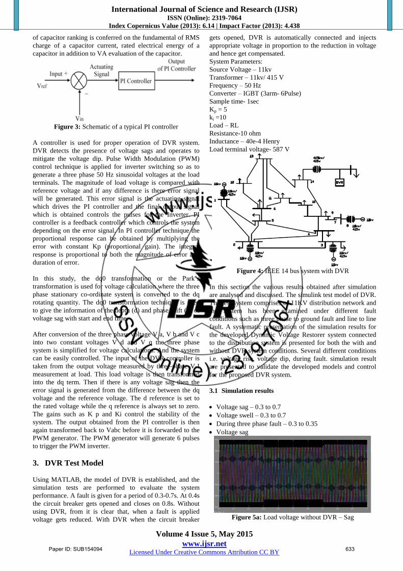
Load terminal voltage- 587 V
Figure 4: IEEE 14 bus system with DVR
In this section the various results obtained after simulation
are analysed and discussed. The simulink test model of DVR.
The test system comprises of 11KV distribution network and
the system has been examined under different fault
conditions such as three phase to ground fault and line to line
fault. A systematic presentation of the simulation results for
the developed Dynamic Voltage Restorer system connected
to the distribution system is presented for both the with and
without DVR system conditions. Several different conditions
i.e. voltage rise, voltage dip, during fault. simulation result
are presented to validate the developed models and control
for the proposed DVR system.
3.1 Simulation results
Voltage sag – 0.3 to 0.7
Voltage swell – 0.3 to 0.7
During three phase fault – 0.3 to 0.35
Voltage sag
Figure 5a: Load voltage without DVR – Sag
Paper ID: SUB154094 633

International Journal of Science and Research (IJSR) ISSN (Online): 2319-7064
Index Copernicus Value (2013): 6.14 | Impact Factor (2013): 4.438
Volume 4 Issue 5, May 2015
www.ijsr.net Licensed Under Creative Commons Attribution CC BY
Figure 5b: Compensated voltage with DVR
Voltage swell
Figure 6a: Load terminal voltage without DVR - Swell
Figure 6b: Compensated voltage with DVR
During fault
A fault is given for a period of 0.3-0.35s. At 0.4s the circuit
breaker gets opened and closes on 0.36s. Without using
DVR, from it is clear that, when a fault is applied voltage
gets reduced. With DVR when the circuit breaker gets
opened, DVR is automatically connected and injects
appropriate voltage in proportion to the reduction in voltage
and hence get compensated.
Figure 7a: During fault
Figure7b: Fault cleared with DVR
4. Conclusion
This paper represents simulation of DVR in MATLAB. In
order to show the performance of DVR in mitigation of
voltage sags, s simple distribution network is simulated using
MATLAB. A DVR is connected to a system through a series
transformer with a capability to insert a maximum voltage of
50% of phase to ground system voltage. In-phase
compensation method is used. DVR injects the appropriate
voltage component to correct rapidly any deviation in the
supply voltage to keep the load voltage constant at the
nominal value and handles both balanced and unbalanced
situations without any difficulties. The main advantages of
the proposed DVR are simple control, fast response and low
cost. The proposed PWM control scheme using PI controller
is efficient in providing the voltage sag compensation. As
opposed to fundamental frequency switching schemes
already available in the MATLAB/SIMULINK, this PWM
control scheme only requires voltage measurements. This
characteristic makes it ideally suitable for low-voltage
custom power applications. The main shortcoming of the
DVR, being a series device, is its inability to mitigate
complete interruptions.
References
[1] Mahaveer Singh , Naveen Sen “Investigation and
Performance Analysis of Distribution System Using
Dynamic Voltage Restorer” International Journal of
Emerging Research in Management &Technology ISSN:
2278-9359 (Volume-3, Issue-7)
[2] Swapnali Hazarika , Swagata Singha Roy, Rahul Baishya
, Smriti Dey “Application of Dynamic Voltage Restorer in
Electrical Distribution System for Voltage Sag
Compensation” The International Journal Of Engineering
And Science (IJES) ||Volume||2 ||Issue|| 7 ||Pages|| 30-
38||2013|| ISSN(e): 2319 – 1813 ISSN(p): 2319 – 1805.
[3] Rosli omar, Nasrudin abd rahim, Marizan sulaiman
”Modeling and simulation for voltage Sags/swells
mitigation using dynamic voltage restorer (dvr)” Journal
of Theoretical and Applied InformationTechnology ©
2005 - 2009 JATIT.
[4] S. Deepa, S. Rajapandian, “Voltage Sag Mitigation Using
Dynamic Voltage Restorer System by Modified Voltage
Source Inverter”, 2nd International Conference on
Electrical, Electronics and Civil Engineering
(ICEECE’2012), pp. 1-4, April 2012.
[5] C. Fitzer, M. Barnes, P. Green, “Voltage Sag Detection
Technique for a Dynamic Voltage Restorer”, IEEE
Paper ID: SUB154094 634

International Journal of Science and Research (IJSR) ISSN (Online): 2319-7064
Index Copernicus Value (2013): 6.14 | Impact Factor (2013): 4.438
Volume 4 Issue 5, May 2015
www.ijsr.net Licensed Under Creative Commons Attribution CC BY
Transactions on Industry application, Issue 1, Vol. 40, pp.
203-212, Feb. 2004.
[6] S.F. Torabi 1 D. Nazarpour
1 Y. Shayestehfard
2
“compensation of sags and swells voltage using dynamic
voltage restorer (dvr) during single line to ground and
three-phase faults” International Journal on “Technical
and Physical Problems of Engineering” (IJTPE), Iss. 12,
Vol. 4, No. 3, Sep. 2012.
[7] S.S.Choi, B.H.Li, D.M.Vilathgamuwa,”Dynamic voltage
restoration with minimum energy injection”,IEEE
transactions on Power Systems, Vol.15, No.1, February
2000, pg.51-57
[8] Kapil P. Radadiya1, Dr. Chirag K. Vibhakar2, Sachin V.
Rajani3and Kishan J. Bhayani4 “Voltage Sag/Swell
Compensation Using Dynamic Voltage Restorer (DVR)”
,2013 Intrenational Conference.
Author Profile
Dhivya. T received the B.E from Sri venkateshwara Institute of
Science And Technology in 2009- 2013 and pursuing degree in
Power systems from SRM University in 2013 – 2015.
Paper ID: SUB154094 635