Analytical Modeling & Simulation of Friction Stir Welding … · · 2017-07-22International...
7
International Journal of Science and Research (IJSR) ISSN (Online): 2319-7064 Index Copernicus Value (2013): 6.14 | Impact Factor (2013): 4.438 Volume 4 Issue 10, October 2015 www.ijsr.net Licensed Under Creative Commons Attribution CC BY Analytical Modeling & Simulation of Friction Stir Welding Process G. Reddy Basha 1 , K. Ashok Kumar 2 1 M.tech (Thermal science and Energy systems) student, Global College of engineering and technology (Affiliated to JNTU Anantapur), Department of Mechanical Engineering, Chennur Road, Kadapa, Kadapa District, Andhra Pradesh, India 2 Assistant professor, Global College of Engineering and Technology (Affiliated to JNTU Anantapur), Department of Mechanical Engineering, Chennur Road, Kadapa, Kadapa District, Andhra Pradesh, India Abstract: Friction stir welding works in the solid state of metals and basic goal of the process is to generate thermal energy by friction between tool and work pieces, which will soften weld pieces and stir it to form the weld. Up to today many people concentrated on different process parameters but they are not concentrated on the initial work which is required to melt the metal to form weld. A plane strain, axis symmetric analyses is used to study the thermo-mechanical instability leading to stirring action for a tool pin rotating at a given RPM. More specifically, the effect of initial work material temperature, tool speed, and tool geometry on size of stir zone and time taken for causing yielding from thermo-mechanical instability is studied. A three-dimensional, finite element material flow and heat transfer model, in a moving co-ordinate system, is developed for analyzing friction stir welding (FSW). Heat input from the tool shoulder and the tool pin are considered here. For validation purpose a bench mark problem is solved using fluent. Keywords: friction, stir, welding, thermal 1. Introduction Friction stir welding (FSW) process first discovered and patented by the Welding Institute of Cambridge U.K. in 1991 by Wayne Thomas and has been since then the subject of a great deal of interest. As per a survey done by Prof. A. P. Reynolds, Guest Editor of Science and Technology of Welding and Joining journal, since 1996, more than 5% of all refereed journal articles related to welding have been friction stir welding articles and if the friction stir processing literature is included this number is even greater. FSW is a solid state joining process that uses friction generated by a rotating cylindrical tool to heat and plasticize metal on either side of a joint, creating a solid, functional weld. The process gives low distortion, can weld thick sections in a single pass and produces welds with excellent mechanical properties. Excellent metallurgical properties, one microstructure, and absence of cracks in the weld zone, high penetration depths, reduced energy requirements, absence of shielding gas, elimination of consumables such as rods and grinding wastes are some of the key benefits of the FSW process over traditional fusion welding techniques. Hence FSW is being increasingly used because of the main feature of a solid- state welding process is the non-melting of the work material which allows a lower temperature and a lower heat input welding process relative to the melting point of materials being joined. This is advantageous over the conventional fusion welding where excessive high heat input is required to melt the work material. Much less heat input required for FSW translates into economic benefits, safer and less complicated welding procedures .The friction stir welding make it possible to join light weight materials such as aluminum alloy, magnesium alloy, copper and titanium alloys which are very difficult to weld by conventional welding. These clear advantages have greatly increased the usage of these materials in structural applications. 2. Literature Review Reynolds et al.,(1999) visualized material flow in two friction stir welds was for different weld parameters Results of the flow visualization show that the FSW process can be roughly described as an in-situ extrusion process wherein the tool shoulder, the weld backing plate and the cold base metal outside the weld zone form an extrusion chamber which moves relative to the work piece .As such, the material is not really stirred across the interface during the friction welding process, at least on a macro level, and the process can be much more accurately described as an in- situ extrusion process than as a stirring process. It also appears that if one discounts the need to heat the material in the weld by friction, the rotation of the tool has only a secondary role to play in weld formation. The whole process may be considered as an extrusion process where the die consists of the tool (both shoulder and pin), the cold material in front of the tool, the cold material beside the tool, and the cold material behind the tool. Muthu kumara, (2004) used solid-mechanics based finite element method with adaptive meshing to simulate the friction stir welding process. Two different interface models with rate-independent material were used to study the material flow. Santiago et al.,(2004) simulated the 3D thermally coupled FSW process and presented the temperature field distribution using a general finite element code. Jayaraman et al., (2008) developed an empirical relationship to predict the tensile strength the friction stir welded cast aluminum alloy using Response Surface Methodology (RSM). Elangovan and Balasubramanian (2006) developed an empirical relationship to predict the tensile Paper ID: SUB158623 44
Transcript of Analytical Modeling & Simulation of Friction Stir Welding … · · 2017-07-22International...
International Journal of Science and Research (IJSR) ISSN (Online): 2319-7064
Index Copernicus Value (2013): 6.14 | Impact Factor (2013): 4.438
Volume 4 Issue 10, October 2015
www.ijsr.net Licensed Under Creative Commons Attribution CC BY
Analytical Modeling & Simulation of Friction Stir Welding Process
G. Reddy Basha
1, K. Ashok Kumar
2
1M.tech (Thermal science and Energy systems) student, Global College of engineering and technology (Affiliated to JNTU Anantapur),
Department of Mechanical Engineering, Chennur Road, Kadapa, Kadapa District, Andhra Pradesh, India
2Assistant professor, Global College of Engineering and Technology (Affiliated to JNTU Anantapur), Department of Mechanical
Engineering, Chennur Road, Kadapa, Kadapa District, Andhra Pradesh, India
Abstract: Friction stir welding works in the solid state of metals and basic goal of the process is to generate thermal energy by
friction between tool and work pieces, which will soften weld pieces and stir it to form the weld. Up to today many people
concentrated on different process parameters but they are not concentrated on the initial work which is required to melt the
metal to form weld. A plane strain, axis symmetric analyses is used to study the thermo-mechanical instability leading to stirring
action for a tool pin rotating at a given RPM. More specifically, the effect of initial work material temperature, tool
speed, and tool geometry on size of stir zone and time taken for causing yielding from thermo-mechanical instability is
studied. A three-dimensional, finite element material flow and heat transfer model, in a moving co-ordinate system, is
developed for analyzing friction stir welding (FSW). Heat input from the tool shoulder and the tool pin are considered here.
For validation purpose a bench mark problem is solved using fluent.
Keywords: friction, stir, welding, thermal
1. Introduction Friction stir welding (FSW) process first discovered and patented by the Welding Institute of Cambridge U.K. in 1991 by Wayne Thomas and has been since then the subject of a great deal of interest. As per a survey done by Prof. A. P. Reynolds, Guest Editor of Science and Technology of Welding and Joining journal, since 1996, more than 5% of all refereed journal articles related to welding have been friction stir welding articles and if the friction stir processing literature is included this number is even greater. FSW is a solid state joining process that uses friction generated by a rotating cylindrical tool to heat and plasticize metal on either side of a joint, creating a solid, functional weld. The process gives low distortion, can weld thick sections in a single pass and produces welds with excellent mechanical properties. Excellent metallurgical properties, one microstructure, and absence of cracks in the weld zone, high penetration depths, reduced energy requirements, absence of shielding gas, elimination of consumables such as rods and grinding wastes are some of the key benefits of the FSW process over traditional fusion welding techniques. Hence FSW is being increasingly used because of the main feature of a solid-state welding process is the non-melting of the work material which allows a lower temperature and a lower heat input welding process relative to the melting point of materials being joined. This is advantageous over the conventional fusion welding where excessive high heat input is required to melt the work material. Much less heat input required for FSW translates into economic benefits, safer and less complicated welding procedures .The friction stir welding make it possible to join light weight materials such as aluminum alloy, magnesium alloy, copper and titanium alloys which are very difficult to weld by conventional welding. These clear advantages have greatly increased the
usage of these materials in structural applications. 2. Literature Review Reynolds et al.,(1999) visualized material flow in two friction stir welds was for different weld parameters Results of the flow visualization show that the FSW process can be roughly described as an in-situ extrusion process wherein the tool shoulder, the weld backing plate and the cold base metal outside the weld zone form an extrusion chamber which moves relative to the work piece .As such, the material is not really stirred across the interface during the friction welding process, at least on a macro level, and the process can be much more accurately described as an in-situ extrusion process than as a stirring process. It also appears that if one discounts the need to heat the material in the weld by friction, the rotation of the tool has only a secondary role to play in weld formation. The whole process may be considered as an extrusion process where the die consists of the tool (both shoulder and pin), the cold material in front of the tool, the cold material beside the tool, and the cold material behind the tool. Muthu kumara, (2004) used solid-mechanics based finite element method with adaptive meshing to simulate the friction stir welding process. Two different interface models with rate-independent material were used to study the material flow. Santiago et al.,(2004) simulated the 3D thermally coupled FSW process and presented the temperature field distribution using a general finite element code. Jayaraman et al., (2008) developed an empirical relationship to predict the tensile strength the friction stir welded cast aluminum alloy using Response Surface Methodology (RSM). Elangovan and Balasubramanian (2006) developed an empirical relationship to predict the tensile
Paper ID: SUB158623 44
International Journal of Science and Research (IJSR) ISSN (Online): 2319-7064
Index Copernicus Value (2013): 6.14 | Impact Factor (2013): 4.438
Volume 4 Issue 10, October 2015
www.ijsr.net Licensed Under Creative Commons Attribution CC BY
strength of the friction stir welded joints of AA2219 Al alloy by means of RSM. Lombord et al., (2008) proposed a systematic approach to optimize FSW process parameters (tool rotational speed and feedrate) through consideration of frictional power input. Rajakumar et al., (2010) proposed models using RSM to predict tensile strength of FSW joints of AA 7075 Al alloy. Zhu et al., (2010) developed relationships between micro-hardness and nano-hardness of dissimilar welding joints of newly developed rotor steels. From the investigation, it was found that the strength distribution in heat affected zone is dependent on the characteristic of micro-structure size. 3. Simulation
3.1 Boundary Conditions
Figure 3.1: Schematic representations of Boundary
conditions which is modeled in fluent Figure3.1 shows the standard set-up for the models. Moreover, based on previous trials (using different meshing schemes table No: 3.1) performed on Fluent, it was observed that the results of such complex CFD models were sensitive to the mesh being used. Hence special attention needs to be given while generating the mesh. The mesh should be symmetric, structured and uniform. Using a boundary layer meshing scheme yielded better results than unstructured triangular grid.
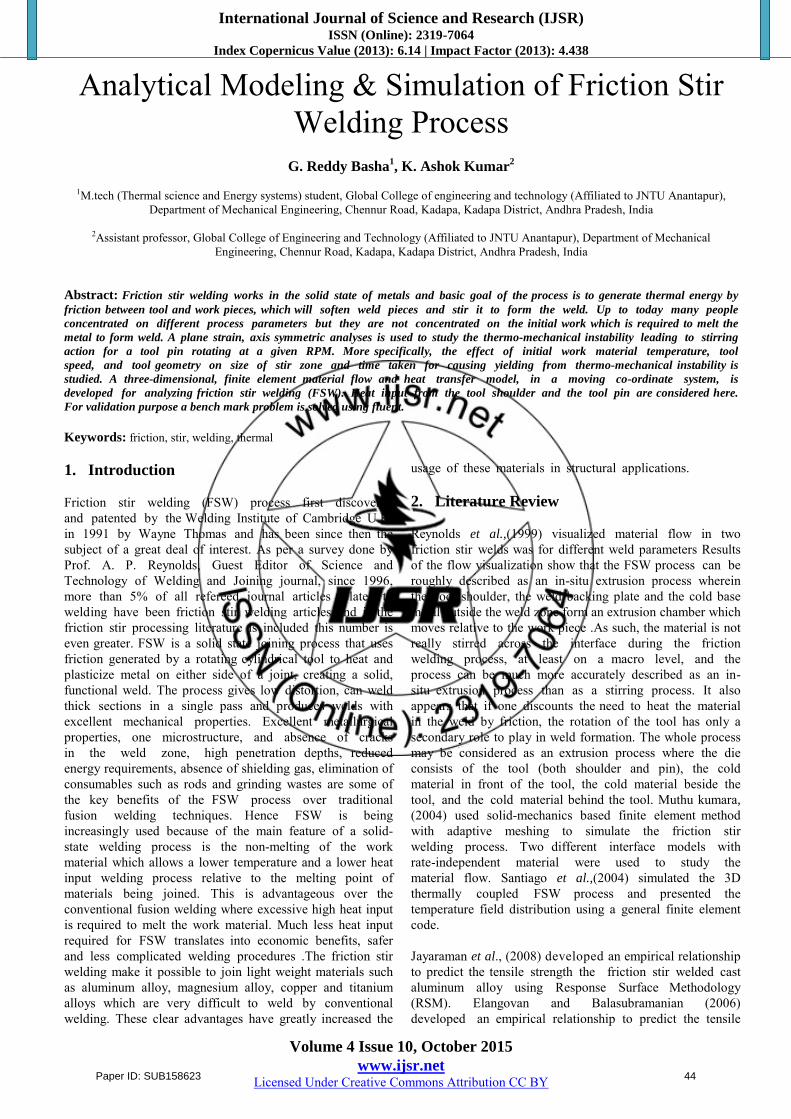
Table 3.1: Observation of different mesh sizes and different number of nodes
3.2 Thermo-Mechanical Instability
By using the codes developed, the FSW process is simulated. For thermo-mechanical instability analysis purpose we are using AL-2124-T851 material is used. The properties of the material are listed below in table No: 4.1. For analysis we are concentrating on two different parameters. They are Case I: Initial temperature Case II: Pin radius.
Table 3.2: Material properties of AL-2124-T851 used for MATLAB coding
Paper ID: SUB158623 45
International Journal of Science and Research (IJSR) ISSN (Online): 2319-7064
Index Copernicus Value (2013): 6.14 | Impact Factor (2013): 4.438
Volume 4 Issue 10, October 2015
www.ijsr.net Licensed Under Creative Commons Attribution CC BY
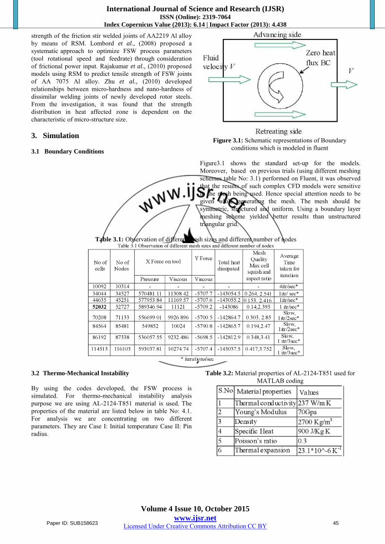
CASE I: Varying the initial temperature
Figure 3.2: Temperature variations for different speeds for
AL-2124-T851 alloy for different initial temperature for a pin radius of 3mm
Figure 3.3: Power variations for different speeds for AL-
2124-T851 for different initial temperature for a pin radius =3mm
From Figure 3.3 shows the power variations per unit length for different speeds. As can be seen from the figures that as the speed increases power required to cause the yielding also increases. Also observe that as the initial temperature increases power required to cause the yielding increases.
Figure 3.4: Time taken for initiation of yielding for different speeds forAL-2124-T851 for different initial temperature for
a pin radius =3mm
From Figure 3.4 shown in below the time taken for initiation of yielding for different speeds. As can be seen from the figures that as the speed increases time taken for initiation of yielding decreases. Also observe that as
the initial temperature increases time taken for initiation of yielding decreases.
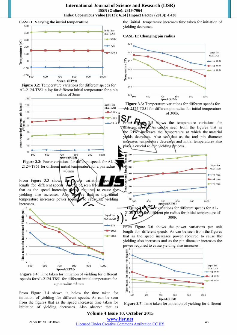
CASE II: Changing pin radius
Figure 3.5: Temperature variations for different speeds for
AL-2124-T851 for different pin radius for initial temperature of 300K
From Figure 3.5 shows the temperature variations for different speeds. As can be seen from the figures that as the RPM increases the temperature at which the material yields decreases. Also see that as the tool pin diameter increases temperature decreases and initial temperatures also plays a crucial role in yielding process.
Figure 3.6: Power variations for different speeds for AL-
2124-T851 for different pin radius for initial temperature of 300K
From Figure 3.6 shows the power variations per unit length for different speeds. As can be seen from the figures that as the speed increases power required to cause the yielding also increases and as the pin diameter increases the power required to cause yielding also increases.
Figure 3.7: Time taken for initiation of yielding for different
Paper ID: SUB158623 46
International Journal of Science and Research (IJSR) ISSN (Online): 2319-7064
Index Copernicus Value (2013): 6.14 | Impact Factor (2013): 4.438
Volume 4 Issue 10, October 2015
www.ijsr.net Licensed Under Creative Commons Attribution CC BY
speeds for AL-2124-T851 for different pin radius for initial temperature of 300K
From Figure 3.7 shown below the time taken for initiation of yielding for different speeds. As can be seen from the figures that as the speed increases time taken for initiation of yielding decreases and as the pin diameter increases the time taken for initiation of yielding decreases. 4. Numerical Simulations Using Fluent For modeling purpose, pressure based solver using a coupled algorithm was used. Since the momentum and continuity equations are solved in a closely coupled manner, the rate of solution convergence significantly improves when compared to the segregated algorithm. However, the memory requirement increases by 1.5 - 2 times that of these aggregated algorithm since the discrete system of all momentum and pressure-based continuity equations needs to be stored in the memory when solving for the velocity and pressure fields (rather than just a single equation, as is the case with the segregated algorithm). FLUENT has an inbuilt non-Newtonian power law model of viscosity and the temperature dependent material, specific heat and thermal conductivity properties as taken from equation 3.1.Figures shown here are results of the simulation for cylindrical tool for one set of parameters i.e. V=1.28mm/s and ω=240 RPM. Temperature, Velocity, Pressure and path line contours in the flow domain were obtained.
Figure 4.1: Imported mesh file from GAMBIT
Figure 4.1 represents the meshed file, which is meshed by using GAMBIT 6.1. Then file is imported into FLUENT 12.1. It’s a two dimensional (2d), pressure based coupled (pbns) and laminar flow (lam) analysis. The mesh should be symmetric, structured and uniform. Using a boundary layer meshing scheme yielded better results than unstructured triangular grid.
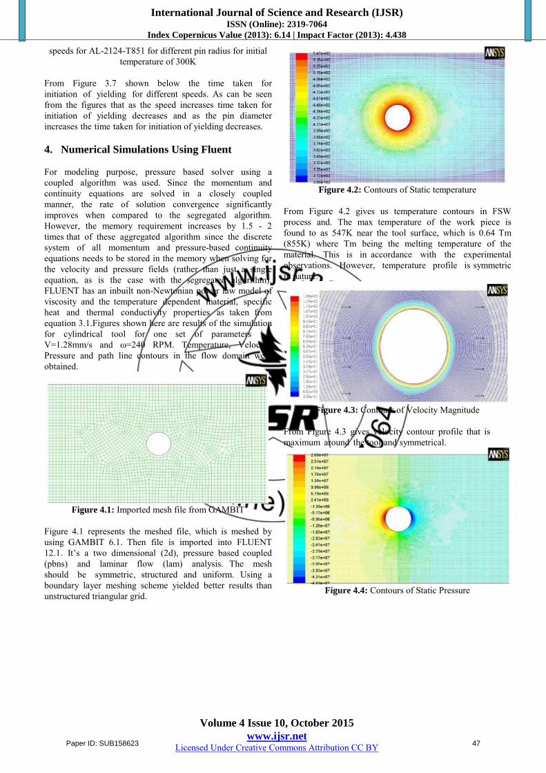
Figure 4.2: Contours of Static temperature
From Figure 4.2 gives us temperature contours in FSW process and. The max temperature of the work piece is found to as 547K near the tool surface, which is 0.64 Tm (855K) where Tm being the melting temperature of the material. This is in accordance with the experimental observations. However, temperature profile is symmetric in nature.
Figure 4.3: Contours of Velocity Magnitude
From Figure 4.3 gives velocity contour profile that is maximum around the tool and symmetrical.
Figure 4.4: Contours of Static Pressure
Paper ID: SUB158623 47
International Journal of Science and Research (IJSR) ISSN (Online): 2319-7064
Index Copernicus Value (2013): 6.14 | Impact Factor (2013): 4.438
Volume 4 Issue 10, October 2015
www.ijsr.net Licensed Under Creative Commons Attribution CC BY
Figure 4.5: Contours of path lines colored by stream function In Figure 4.11material flow is from the right to the left past the anti-clockwise rotating pin. The streamlines in the flow domain suggest that material originally within the pin diameter is transported around the pin in the rotation direction only. No material within the pin diameter passes the pin on the advancing side where as all the material is transported around the retreating side. The width of the deformed region is smaller on the advancing side than on the retreating side. This observation is in accordance with the experimental results. Case I: Constant Tool Speed (600 RPM) By keeping tool speed constant varying the weld speed (0.5 to 1.25mm/s) with different process parameters. It is also observed form Figures (4.6 to 4.10) that with increasing the weld speed maximum observed temperature increases, torque required decreases, power required increases, total heat dissipation decreases, pressure force and viscous force on force acting on the tool along weld direction increases although effect viscous force is less compared to that of pressure force, pressure force and viscous force on force acting on the tool perpendicular to the weld direction increases but viscous force variation is more compared to that of pressure force.
Figure 4.6: Effect of weld speed forAA6061 alloy for a tool
speed of 600RPM on Temperature
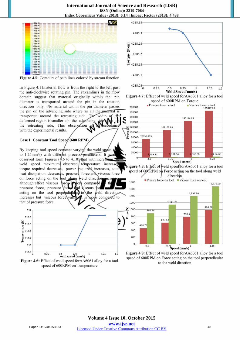
Figure 4.7: Effect of weld speed forAA6061 alloy for a tool
speed of 600RPM on Torque
Figure 4.8: Effect of weld speed forAA6061 alloy for a tool
speed of 600RPM on Force acting on the tool along weld direction
Figure 4.9: Effect of weld speed forAA6061 alloy for a tool speed of 600RPM on Force acting on the tool perpendicular
to the weld direction
Paper ID: SUB158623 48
International Journal of Science and Research (IJSR) ISSN (Online): 2319-7064
Index Copernicus Value (2013): 6.14 | Impact Factor (2013): 4.438
Volume 4 Issue 10, October 2015
www.ijsr.net Licensed Under Creative Commons Attribution CC BY
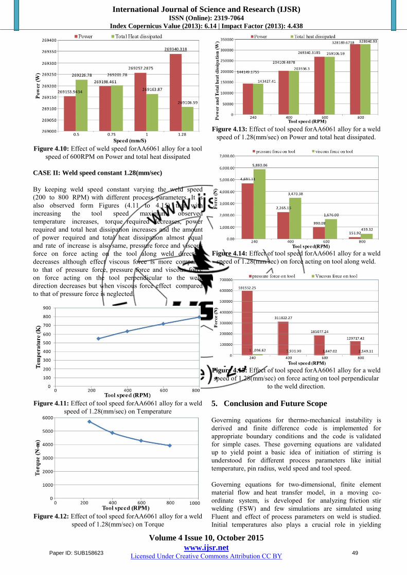
Figure 4.10: Effect of weld speed forAA6061 alloy for a tool
speed of 600RPM on Power and total heat dissipated CASE II: Weld speed constant 1.28(mm/sec) By keeping weld speed constant varying the weld speed (200 to 800 RPM) with different process parameters. It is also observed form Figures (4.11 to 4.15) that with increasing the tool speed maximum observed temperature increases, torque required decreases, power required and total heat dissipation increases and the amount of power required and total heat dissipation almost equal and rate of increase is also same, pressure force and viscous force on force acting on the tool along weld direction decreases although effect viscous force is more compared to that of pressure force, pressure force and viscous force on force acting on the tool perpendicular to the weld direction decreases but when viscous force effect compared to that of pressure force is neglected.
Figure 4.11: Effect of tool speed forAA6061 alloy for a weld
speed of 1.28(mm/sec) on Temperature
Figure 4.12: Effect of tool speed forAA6061 alloy for a weld
speed of 1.28(mm/sec) on Torque
Figure 4.13: Effect of tool speed forAA6061 alloy for a weld
speed of 1.28(mm/sec) on Power and total heat dissipated.
Figure 4.14: Effect of tool speed forAA6061 alloy for a weld
speed of 1.28(mm/sec) on force acting on tool along weld.
Figure 4.15: Effect of tool speed forAA6061 alloy for a weld speed of 1.28(mm/sec) on force acting on tool perpendicular
to the weld direction. 5. Conclusion and Future Scope Governing equations for thermo-mechanical instability is derived and finite difference code is implemented for appropriate boundary conditions and the code is validated for simple cases. These governing equations are validated up to yield point a basic idea of initiation of stirring is understood for different process parameters like initial temperature, pin radius, weld speed and tool speed. Governing equations for two-dimensional, finite element material flow and heat transfer model, in a moving co-ordinate system, is developed for analyzing friction stir welding (FSW) and few simulations are simulated using Fluent and effect of process parameters on weld is studied. Initial temperatures also plays a crucial role in yielding
Paper ID: SUB158623 49
International Journal of Science and Research (IJSR) ISSN (Online): 2319-7064
Index Copernicus Value (2013): 6.14 | Impact Factor (2013): 4.438
Volume 4 Issue 10, October 2015
www.ijsr.net Licensed Under Creative Commons Attribution CC BY
process, if the initial temperature is low i.e., at -196 0C (77K) then the material is yielding at below zero degree C. At maximum pin radius and speed (5mm&1000 RPM) time taken for initiation yielding is almost 1 sec. The material around the pin will generate large thermal plastic strain during. FSW temperature dependent were used. At high temperatures rate-dependent effects become important. In FSW, the temperatures near the pin are high enough (0.6-0.8Tm) to make the material soft. Higher tool rotation rates generate higher temperature because of higher friction heating and result in more intense stirring and mixing of material. Future Scope In present problem plasticity conditions and the effect of tool properties can be considered in the analyses. Finite element problem can be implemented in MATLAB Fluent analyses can be extended to 3-D. References
[1] W.M. Thomas, E.D. Nicholas, J.C. Needham, M.G. Murch, P.Templesmith, C.J. Dawes. G.B, “Patents on Friction Stir Butt Welding”, Patent Application No.9125978.8, 1991.
[2] Murshid Imam, KajalBiswas, “Weld zone modeling in friction stir welds in AA 6063-T4”, Fourth International Congress on Computational Mechanics and Simulation, IIT Hyderabad, 2012, pp 12.
[3] C. Dawes, W. Thomas, Training Within Industry Bulletin 6, 1995, pp124.
[4] American Welding Society, “Welding Handbook”, 9th Edition, Volume: 3, Welding Process, American Welding Society, 2007.
[5] Schneider JA, Nunes Jr AC. “Thermo-mechanical processing in friction stir welds”, Proceedings of symposium sponsored by the shaping and forming committee of the materials processing and manufacturing division of the minerals, metals, and materials society (TMS),Warrendale (PA), TMS, 2003, pp 43– 51.
[6] Y. S. Sato, M. Urata and H. Kokawa, “Parameters Controlling Microstructure and Hardness during Friction-Stir Welding of Precipitation-Hardenable Aluminum Alloy 6063”, Metallurgical and Materials Transactions A, volume: 33, 2002, pp 625-635.
[7] T.R. McNelley, S. Swaminathan, J.Q. Su, “Recrystallization mechanisms during friction stir welding/processing of aluminum alloys”, Script Material, Volume: 58, Issue 5, March 2008, pp 349–354.
[8] Y. S. Sato, M. Urata, H. Kokawa and K. Ikeda, “Hall-Petch relationship in friction stir welds of equal channel angular-pressed aluminium alloys”, Materials Science and Engineering A, volume 354, 2004, pp 298-305.
[9] Liu. G, Murr L.E, Niou C.S, McClure and J.C. Vega, “Micro- structural aspects of the friction-stir welding of
6061-T6 aluminum alloy”, Science and materials, volume: 37, 1997, pp 335.
[10] K. N. Krishnan, “On the formation of onion rings in friction stir welds”, Materials Science and Engineering A, volume: 327, 2002, pp 246-251.
[11] V. Balasubramanian, “Relationship between base metal properties and friction stir welding process parameters”, Material Science and Engineering A, volume: 480(1-2), 2008, pp 397-403.
Author Profile
G. Reddy Basha received the B.Tech degree in Mechanical Engineering from S.V University (K.S.R.M Engineering College) in 2013.And presently studying M. Tech (Thermal Science and Energy Systems) IInd year in Global College of Engineering and Technology, Kadapa.
K. Ashok Kumar received the B.Tech degree in mechanical Engineering from K.S.R.M engineering college, Kadapa in 2003 and received M.Tech degree in Industrial engineering & management from NIT Calicut in 2006. He had eight and half years of teaching
experience in mechanical engineering field. And presently he working as Assistant professor in Department of mechanical engineering at Global College of engineering and Technology, Kadapa (Affiliated to JNTU Anantapur). He had also published several journals in the Mechanical Engineering field.
Paper ID: SUB158623 50