Implementation of Convolutional Encoder and Viterbi ... · Implementation of Convolutional Encoder...
17
Transcript of Implementation of Convolutional Encoder and Viterbi ... · Implementation of Convolutional Encoder...

Implementation of ConvolutionalEncoder and Viterbi Decoder using
VHDL in FPGA
Sumit Kumar Pramanick, Shuvadeep Kumar, DESE, IISc, Bangalore
April 28, 2012

Contents
1 Introduction 21.1 Convolutional Encoder . . . . . . . . . . . . . . . . . . . . . . . . . . . . . 21.2 Viterbi Decoder . . . . . . . . . . . . . . . . . . . . . . . . . . . . . . . . . 2
2 Implementation and Hardware 52.1 Convolutional Encoder . . . . . . . . . . . . . . . . . . . . . . . . . . . . . 52.2 Viterbi Decoder . . . . . . . . . . . . . . . . . . . . . . . . . . . . . . . . . 6
2.2.1 Add Compare and Select Module (ACS) . . . . . . . . . . . . . . . 62.2.2 Controller . . . . . . . . . . . . . . . . . . . . . . . . . . . . . . . . 72.2.3 Memory . . . . . . . . . . . . . . . . . . . . . . . . . . . . . . . . . 82.2.4 Input Sequence Predictor(ISP) . . . . . . . . . . . . . . . . . . . . . 9
3 Results and Performance 103.1 Timing Analysis . . . . . . . . . . . . . . . . . . . . . . . . . . . . . . . . . 103.2 Resource Utilization . . . . . . . . . . . . . . . . . . . . . . . . . . . . . . 103.3 Simulation waveforms . . . . . . . . . . . . . . . . . . . . . . . . . . . . . . 12
4 Challenges and Scope 15
1

Chapter 1
Introduction
In a typical data transmission scheme the data from the source is encoded to digital by thesource encoder, which most of the time is a A/D conversion unit. The work done here isa part of that data transmission scheme which follows after souce encoding. The convolu-tional encoder implemented here is the channel encoder in the data transmission scheme,which encodes the digital data from the source encoder �t for transmission through thechannel considering all the constraints disturbances in the transmission medium.The Viterbi decoder implemented here is the channel decoder which decodes the encodeddata stream received from the channel and decodes the original data that was originallymeant for exchange and subsequntly encoded. The Viterbi decoder uses maximum likeli-hood decoding algorithm[1] proposed by Andrew Viterbi.In the following sections a brief description about convolutional encoder and Viterbi de-coder is given.
1.1 Convolutional Encoder
Convolution encoding is a coding technique which is extensively used in the combatingthe issue of channel noise. This is done by adding redundant bits to the convolutionalcode. Unlike a block code, a convolutional code is dependent on the present input sequenceas well as some previous input. Thus memory is involved in the convolutional encoder tohold the previous input. The convolutional encoder is thus essentially a sequential circuit.A convolutional code which accepts k-bit blocks of information and produces n-bit encodedsequence, with a memory of m input blocks is termed as (n,k,m) convolutional code. Inour work a (2,1,2) convolutional code is implemented in the encoder.
1.2 Viterbi Decoder
For maximum likelihood decoding for convolutional codes the Viterbi algorithm �ndsthe most probable path for a given input sequence. As shown in Fig 1.2.1 for an inputsequence u to the encoder a coded word a is produced. In the receving side for a receivedsequence r the decoder gives output â. Now for information sequence u the decoder mustproduce û, likewise there is a one to one correspondence between u and a. Thus fora code a the decoder output is â. Now û=u i� â=a. So for a received sequence thedecoding strategy should be such that â=a. Now, decoding error takes place when â6=a.For a received sequence r the probability of this error is P(E|r) has to be minimized usingViterbi algorithm. This is done by the subsequent steps enumerated.
2

CHAPTER 1. INTRODUCTION 3
Figure 1.2.1: General data transmission scheme
1. For a general m memory convolutional code there can be 2mdi�erent states. For kmemory there can be 2kdi�erent input combinations. When the encoder memoryis in one of these 2mstates if one of the 2k is applied, then a state transition in thememory takes place with a output of n bits. By this logic a Trellis diagram as shownin Fig 1.2.2 can be drawn.
2. Thus a state in one stage can be reached by 2kdi�erent paths from the previousstage.
3. The encoder and decoder is set to start its operation from a �xed state. Now forevery received sequence by the decoder the branch metric is calculated, whichis nothing but the hamming distance from ideal bit sequence (e.g. 00, 01, 10, 11are ideal sequence for 2 bit operation). Thus the input sequence is compared withall the possible paths that lead to the present state and the path which has theminimum branch metric is chosen. By doing this, the most likely convolution codesent by the encoder is predticted by the decoder, thus minimizing the error.
4. For every stage the path metric is calculated. Path metric is the summation ofthe weight of the state and the corresponding branch metric for paths convergingto a state. Whichever path has minimum path metric that is stored in the memoryat every stage.
5. Once the information sequence of a particular depth is received the trace back isdone by reading the path metric data from the memory. The trace back gives acomplete sense of the states in the path at every clock cycle (stage), thus the inputinformation sequence is decoded (â) from that.

CHAPTER 1. INTRODUCTION 4
Figure 1.2.2: Trellis diagram for a (2,1,2) convolutional code

Chapter 2
Implementation and Hardware
2.1 Convolutional Encoder
As described in section 1.1 in Chapter 1, the convolutional code from a convolutionalencoder is not only dependent on the current input but also the previous inputs. In theencoder implemented in this work, the input to the encoder is 1-bit (dn), the output is2 bits (x1x0) as shown in Fig. 2.1.1. The two registers used holds the previous 2 inputs(dn−1dn−2), thus it acts as a memory. Upon every clock edge the memory is updated. Theoutput is generated using one 2 input and one 3 input XOR gate. The ouput is expressedby the equation as shown below:
xi = dn +i∑
z=0
dn−m−z m = memory of encoder
Figure 2.1.1: Hardware of the convolutional encoder
The output can also be expressed by the impulse response of the encoder. The impulseresponse is encoder output obtained by giving a sequence din= {1,0,0,0....}. Let theimpulse response be g0and g1. Thus from the hardware shown in Fig. 2.1.1 g0and g1canis derived as:
g0 = (1 0 1) g1 = (1 1 1)
Thus at any instant l of the input sequence the output can be de�ned as,
5
CHAPTER 2. IMPLEMENTATION AND HARDWARE 6
xli=
m∑z=0
dl−zg iz
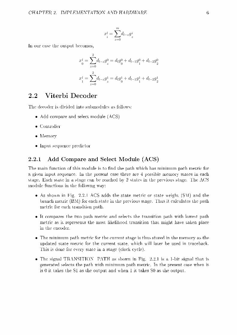
In our case the output becomes,
x l0=
2∑z=0
dl−zg0z= dlg0
0+ dl−1g0
1+ dl−2g0
2
x l1=
2∑z=0
dl−zg1z= dlg1
0+ dl−1g1
1+ dl−2g1
2
2.2 Viterbi Decoder
The decoder is divided into submodules as follows:
• Add compare and select module (ACS)
• Controller
• Memory
• Input sequence predictor
2.2.1 Add Compare and Select Module (ACS)
The main function of this module is to �nd the path which has minimum path metric fora given input sequence. In the present case there are 4 possible memory states in eachstage. Each state in a stage can be reached by 2 states in the previous stage. The ACSmodule functions in the followng way:
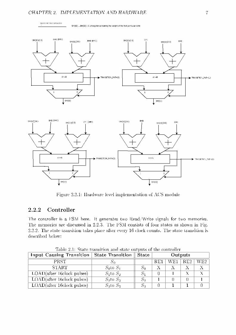
• As shown in Fig. 2.2.1 ACS adds the state metric or state weight (SM) and thebranch metric (BM) for each state in the previous stage. Thus it calculates the pathmetric for each transition path.
• It compares the two path metric and selects the transition path with lowest pathmetric as it represents the most likelihood transition that might have taken placein the encoder.
• The minimum path metric for the current stage is thus stored in the memory as theupdated state metric for the current state, which will later be used in traceback.This is done for every state in a stage (clock cycle).
• The signal TRANSITION_PATH as shown in Fig. 2.2.1 is a 1-bit signal that isgenerated selects the path with minimum path metric. In the present case when itis 0 it takes the S1 as the output and when 1 it takes S0 as the output.
CHAPTER 2. IMPLEMENTATION AND HARDWARE 7
Figure 2.2.1: Hardware level implementation of ACS module
2.2.2 Controller
The controller is a FSM here. It generates two Read/Write signals for two memories.The memories are discussed in 2.2.3. The FSM consists of four states as shown in Fig.2.2.2. The state transition takes place after every 16 clock counts. The state transition isdescribed below:
Table 2.1: State transition and state outputs of the controllerInput Causing Transition State Transition State Outputs
PRST S0 RE1 WE1 RE2 WE2START S0to S1 S0 X X X X
LOAD(after 16clock pulses) S1to S2 S1 0 1 X XLOAD(after 16clock pulses) S2to S3 S2 1 0 0 1LOAD(after 16clock pulses) S3to S2 S3 0 1 1 0

CHAPTER 2. IMPLEMENTATION AND HARDWARE 8
Figure 2.2.2: State diagram of the controller FSM
2.2.3 Memory
The memory is used here to store the transition path for each step every clock cycle. A 1in the memory data corresponds to the upper path and 0 corresponds to the lower pathas shown in Trellis Diagram in Fig. 1.2.2. The data depth taken here is 16bits. So asshown in the Fig. 2.2.3 there are 16 address in the memory, hence 4-bit row decoder.The coloumn decoder selects the memory bank to be used. Since the data comes as acontinuous stream when the read operation of one memory bank is done and sent to theInput Sequence Predictor, simultaneously write operation also needs to done. This is donein two memory banks where read and write operation are done alternatively in every 16clock cycles. The read, write enable signals are coming from the controller as describedin 2.2.2.
Figure 2.2.3: Schematic of the memory used in the Viterbi Decoder

CHAPTER 2. IMPLEMENTATION AND HARDWARE 9
2.2.4 Input Sequence Predictor(ISP)
Input Sequence Predictor is a FSM. When the transition path is being read from thememory at every stage and from the current state of the decoder in the Tellis Diagram,the previous state is deciphered by this FSM whose state transition is shown in Fig.2.2.4. Now as the previous state is deciphered the input which caused the state transitionis predicted.
Figure 2.2.4: Melay machine and its state diagram for Input Sequence Predictor
As we can see the output from the ISP will be in the reverse order of the input. So thisoutput from ISP is stored in a LIFO to obtain the input in the correct order. The LIFOschematic is shown in Fig. 2.2.5. The UP/DOWN signal to the LIFO determines whetherthe data is being pushed or popped into the LIFO. Hence the �rst output comes after32-clock cycles.
Figure 2.2.5: LIFO schematic
It should be noted the design has been done considering the decoder is starting from stateS2 and the decoder works on the principle of �nding the most probable path from S2 tothe same state after 16 clock cycles. Hence the last two bits of the input in every 16 clockcycles should be 1.

Chapter 3
Results and Performance
3.1 Timing Analysis
The post route and synthesis timing report is provided below:
• Minimum period- 9.842ns
• Maximum frequency - 101.609MHz
• Minimum input arrival time before clock - 2.369ns
• Maximum output required time after clock - 5.877ns
3.2 Resource Utilization
The utilization of the the logic blocks in the FPGA post systhesis of the ConvolutionalEncoder and Viterbi Decoder are shown in Table 3.2. In Fig.3.2.1 the complete systemof the viterbi decoder is shown.
Table 3.1: Resource Utilization of the Convolutional Encoder and Viterbi Decoder com-bined in FPGA
Logic Utilization Used Available Utilization(%)
Total number of slice register 75 9312 1Number used as Flip-Flops 73Number used as Latches 2
Number of 4 input LUTs 168 9312 1Number used as logic 160 168 95Number used as 16X1 RAMS 8 168 5
Number of occupied slices 93 4656 1Slices with only related logic 93 93 100Slices with unrelated logic 0 93 0
Number of bonded IOBs 5 232 2
Number of BUFGMUXs 1 24 4
Average Fanout of Non-Clock Nets 3.95
10

CHAPTER 3. RESULTS AND PERFORMANCE 11
Figure
3.2.1:
Com
plete
hardwarefortheviterbidecoder

CHAPTER 3. RESULTS AND PERFORMANCE 12
3.3 Simulation waveforms
The hardware is implemented in Xilinx Spartan 3E board. A channel has also beenintroduced through hardware using VHDL in the board, whose bit error rate can bemodi�ed (0.1 and 0.2 taken in our case). The corresponding output is viewed throughChipScope through the JTAG connection with the board. The Decoder output withoutuse of channel is shown in Fig. 3.3.1. The output waveforms from the Decoder are shownin Fig. 3.3.2 and Fig. 3.3.3.
Figure 3.3.1: The Decoder output without use of channel

CHAPTER 3. RESULTS AND PERFORMANCE 13
Figure 3.3.2: Decoder output with BER of 0.1 in channel
Figure 3.3.3: Decoder output with BER of 0.2 in channel
CHAPTER 3. RESULTS AND PERFORMANCE 14
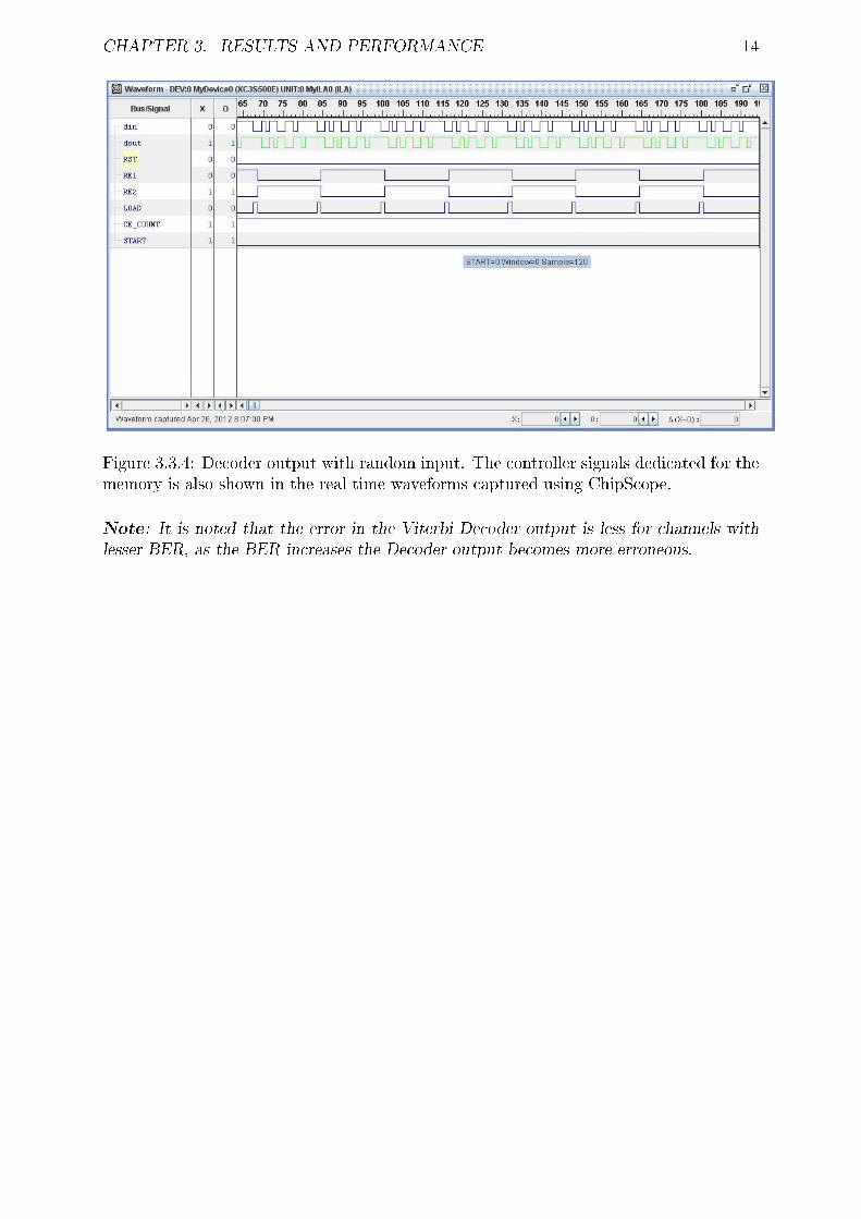
Figure 3.3.4: Decoder output with random input. The controller signals dedicated for thememory is also shown in the real time waveforms captured using ChipScope.
Note: It is noted that the error in the Viterbi Decoder output is less for channels with
lesser BER, as the BER increases the Decoder output becomes more erroneous.

Chapter 4
Challenges and Scope
While implementation of the Viterbi Decoder following challenges were faced:
• Designing the memory for storage of the transition paths at each stage. While thetransition paths for the newly encoded inputs are to be written to the memory, thealready stored transition paths are also needed to be read. Hence two memory unitsare used in this case.
• The Decoder output were coming out in reverse order of the input sequence. Tocorrect the order a LIFO was introduced in the output. But by doing this the initialdata comes only after 32 clock cycles. Thus the latency increased.
Further development of the Decoder can be done in the following areas:
• The Viterbi Decoder is mostly used in Communication systems where signal to noiseratio is improved by performing most likelihood decoding. But, the disadvantage isViterbi Decoder is slow. For a single bit of decoding 2k operations needs to be done,where k is the number of memory of the convolutional encoder. By implementinga Lazy Viterbi Algorithm [3] these number of operations can be reduced to k, thusreducing the decoding time by doing away with exponential dependency on k.
15

Bibliography
[1] Viterbi AJ (April 1967). "Error bounds for convolutional codes and anasymptotically optimum decoding algorithm". IEEE Transactions on In-formation Theory
[2] Error Control Coding : Fundamentals and Applications by Shu Lin andDaniel J. Costello Jr.
[3] �Jon Feldman ,Ibrahim Abou-Faycal and Matteo Frigo�. A Fast Maximum-Likelihood Decoder for Convolutional Codes by
[4] �Yin Sweet Wong, Wen Jian Ong, Jin Hui Chong, Chee Kyun Ng, NorKamariah Noordin� Implementation of Convolutional Encoder and ViterbiDecoder using VHDL . Proceedings of 2009 IEEE Student Conference onResearch and Development (SCOReD 2009)
16


![Contents · Figure 1.2: The (n,k,ν) convolutional encoder In 1976, Viterbi [1] introduced a decoding algorithm for convolutional code. And Omura [2] showed that the Viterbi Algorithm](https://static.fdocuments.in/doc/165x107/5e98b65866b80e2e6461d1ff/contents-figure-12-the-nk-convolutional-encoder-in-1976-viterbi-1-introduced.jpg)