David A. Ladner (ladner@uiuc) University of Illinois at Urbana-Champaign
International Journal of Emerging Engineering Research and Technology
Volume 4, Issue 1, January 2016, PP 1-11
ISSN 2349-4395 (Print) & ISSN 2349-4409 (Online)
*Address for correspondence:
International Journal of Emerging Engineering Research and Technology V3 ● I12 ● December 2016 1
Implementation of Carry Tree Adders and Compare with RCA
and CSLA
G. Venkatanaga Kumar 1, C.H Pushpalatha
2
Department of ECE, GONNA INSTITUTE OF TECHNOLOGY, Vishakhapatnam, India (PG Scholar)
Department of ECE, GONNA INSTITUTE OF TECHNOLOGY, Vishakhapatnam, India (Associate Professor)
ABSTRACT
The binary adder is the critical element in most digital circuit designs including digital signal processors
(DSP) and microprocessor data path units. As such, extensive research continues to be focused on improving
the power delay performance of the adder. In VLSI implementations, parallel-prefix adders are known to
have the best performance. Binary adders are one of the most essential logic elements within a digital system.
In addition, binary adders are also helpful in units other than Arithmetic Logic Units (ALU), such as
multipliers, dividers and memory addressing. Therefore, binary addition is essential that any improvement in
binary addition can result in a performance boost for any computing system and, hence, help improve the
performance of the entire system. Parallel-prefix adders (also known as carry-tree adders) are known to have
the best performance in VLSI designs. This paper investigates three types of carry-tree adders (the Kogge-
Stone, sparse Kogge-Stone, Ladner-Fischer and spanning tree adder) and compares them to the simple Ripple
Carry Adder (RCA) and Carry Skip Adder (CSA). In this project Xilinx-ISE tool is used for simulation,
logical verification, and further synthesizing. This algorithm is implemented in Xilinx 13.2 version and
verified using Spartan 3e kit.
Keywords: Ladner-Fischer, Sparse kogge stone logics.
INTRODUCTION
The first semiconductor chips held one transistor each, subsequent advances added more and more
transistors and as a consequence more individual functions or systems were integrated over time.
The first integrated circuits held only a few devices, perhaps as many as ten diodes, transistors,
resistors and capacitors, making it possible to fabricate one or more logic gates on a single device.
Now known respectively as "small-scale integration" (SSI), improvements in technique led to
devices with hundreds of logic gates, known as large-scale integration (LSI) i.e., systems with at
least a thousand logic gates. Current technology has moved far past this mark and today's
microprocessors have many millions of gates and hundreds of millions of individual transistors.
At one time, there was an effort to name and calibrate various levels of large-scale integration
above VLSI. Terms like Ultra-large-scale Integration (ULSI) were used. But the huge number of
gates and transistors available on common devices has rendered such fine distinctions moot. Terms
suggesting greater than VLSI levels of integration are no longer in widespread use. Even VLSI is
now somewhat quaint, given the common assumption that all microprocessors are VLSI or better.
As of early 2008, billion-transistor processors are commercially available, an example of which is
Intel's Montecito Itanium chip. This is expected to become more commonplace as semiconductor
fabrication moves from the current generation of 65 nm processes to the next 45nm generation

G. Venkatanaga Kumar & C.H Pushpalatha “Implementation of Carry Tree Adders and Compare with
RCA and CSLA”
2 International Journal of Emerging Engineering Research and Technology V4 ● I1 ● January 2016
(while experiencing new challenges such as increased variation across process corners).This
microprocessor is unique in the fact that its 1.4 Billion transistor count, capable of a teraflop of
performance, is almost entirely dedicated to logic. Current designs, as opposed to the earliest
devices, use extensive design automation and automated logic synthesis to layout the transistors,
enabling higher levels of complexity in the resulting logic functionality. Certain high performance
logic blocks like the SRAM cell, however, are still designed by hand to ensure the highest
efficiency.
PARALLEL PREFIX ADDERS
Parallel-prefix adders, also known as carry-tree adders, pre-compute the propagate and generate
signals. These signals are variously combined using the fundamental carry operator (fco).
(gL, pL) ο (gR, pR) = (gL+ pL•gR, pL• pR)
Due to associative property of the fco, these operators can be combined in different ways to form various adder structures. For, example the four-bit carry look-ahead generator is given by
c4= (g4, p4) o [(g3, p3) ο [(g2, p2) ο (g1, p1)]]
A simple rearrangement of the order of operations allows parallel operation, resulting in a more efficient tree structure for this four bit example is
c4= [(g4, p4) ο (g3, p3)] ο [(g2, p2) ο (g1, p1)]
It is readily apparent that a key advantage of the tree structured adder is that the critical path due to the
carry delay is on the order of log2N for an N-bit wide adder. The arrangement of the prefix network
gives rise to various families of adders. Here BC is designated as the black cell which generates the
ordered pair in equation, the gray cell (GC) generates the left signal only. The interconnect area is
known to be high, but for an FPGA with large routing overhead to begin with, this is not as important
as in a VLSI implementation.
The regularity of the Kogge-Stone prefix network has built in redundancy which has implications for
fault-tolerant designs. This hybrid design completes the summation process with a 4-bit RCA allowing
the carry prefix network to be simplified. Parallel prefix adders allow more efficient implementations
of the carry look-ahead technique and are essentially, variants of carry look-ahead adders. Indeed, in
current technology, parallel prefix adders are among the best adders, with respect to area and time is
particularly suited for high speed addition of large numbers.
In these parallel prefix adders, mainly two types of Generate and Propagate bits are present. Generate
and Propagate concept is extendable to blocks comprising multiple bits. For each bit i of the adder,
Generate (Gi) indicates whether a carry is generated from that bit and
Gi= ai&bi
For each bit i of the adder, Propagate (Pi) indicates whether a carry is propagated through that bit
Pi = ai bi
STRUCTURE OF THE PARALLEL PREFIX ADDERS
Fig3.1. Parallel prefix adder structure

G. Venkatanaga Kumar & C.H Pushpalatha “Implementation of Carry Tree Adders and Compare with
RCA and CSLA”
International Journal of Emerging Engineering Research and Technology V4 ● I1 ● January 2016 3
A parallel prefix adder employs 3-stage structure of carry look-ahead adder. The improvement is that
the carry generation stage which is the most intensive one. The Fig3.1 shows the structure of ling
adder. The ling adder uses predetermined propagates and generate in 1st stage of design. The 2nd
stage is parallelizable to reduce time by calculating carries. The 3rd stage is the simple adder block to
calculate the sum.
PROCESSING COMPONENT STRUCTURE
In order to achieve the tree operation for the parallel prefix adders, processing component structure is
needed. Where it takes the Pin, Gin as the inputs and processes them to the other Pout and Gout
outputs. Here one of it is to the next stage and another one to the continuous process. Fig 3.2 shows
the processing component structure.
Fig3.2. Processing component structure
The parallel prefix graph for representation of prefix addition is shown in Fig 3.3.
Fig3.3. Parallel prefix adder structure
LADNER-FISCHER ADDER
In 1980, Fischer and Richard Ladner presented a parallel algorithm for computing prefix sums
efficiently. They show how to construct a circuit that computes the prefix sums in the circuit; each
node performs an addition of two numbers. With their construction, one can choose a trade-off
between the circuit depth and the number of nodes.
Ladner and Fischer defined the prefix problem as: Let “o” be an associative operation on n inputs
x1,….., xn, to compute each of products x1ox2o….oxk,1 ≤ k≤n. In the application of binary
addition, the input of prefix computation is a group of binary vectors with two domains gi(generate)
and pi(propagate):

G. Venkatanaga Kumar & C.H Pushpalatha “Implementation of Carry Tree Adders and Compare with
RCA and CSLA”
4 International Journal of Emerging Engineering Research and Technology V4 ● I1 ● January 2016
(Pre-processing)
If gi equals 1, a carry is generated at bit i; otherwise if pi equals 1, a carry is propagated through bit
i. By prefix computation, the concept of generate and propagate can be extended to multiple bits.
We define G[i: k] and P[i: k] (i≥ k) as:
(Prefix-computation)
To simplify the representation, we continue to use the same operator to denote the prefix
computation on (G; P):(G; P)[i:k] = (G; P) [i:j]o(G; P)[j-1:k]
The width of the (G; P) term is calculated by i-k + 1. For final outputs, Si and Ci can be generated
from G and P:Ci= G[i:0] Si= pici-1
(Post-processing)
Since pre-processing and post-processing have constant delay, prefix computation becomes the core
of prefix adders and dominates the performance. A visual representation of prefix computation
structures is to use directed acyclic graphs. For (G; P) computation in binary addition problem, it
has two important properties:
Property 1: (G; P) computation is associative. That is
(G; P)[i:k] = (G; P)[i:j] o (G; P)[j-1:k]
= (G; P)[i:l] o(G; P)[l-1:k]; i ≥ l; j > k
Property 2: (G; P) computation is idempotent. That is
(G; P)[i:k] = (G; P)[i:j] o(G; P)[j-1:k]
= (G; P)[i:j] o(G; P)[l:k]; i ≥ l > j- 1 ≥ k
These two properties limit the design space of parallel prefix adders. That is the solution space of
(G; P) computation covers every tree-like structures defined under bit width n. However, the same
circuit designs were already studied much earlier in Soviet mathematics. This also has O(log2n)
stages. Its prefix graph is shown in Fig 3.9.The Ladner Fischer Parallel Prefix Adder (LFPPA) is
presented graphically represents the connection of carry operator node in LFPPA for the case of n =
8. The number of majority gates required for an n-bit Ladner–Fischer adder is given by

G. Venkatanaga Kumar & C.H Pushpalatha “Implementation of Carry Tree Adders and Compare with
RCA and CSLA”
International Journal of Emerging Engineering Research and Technology V4 ● I1 ● January 2016 5
Fig3.9. 16-bit Ladner–Fischer adder prefix graph
The direct calculation of the carries, denoted by is given by
Here associative operations are applied in stage 1and stage log2n. This leads to a reduction of
majority gates, denoted Ir(n), given by
The overall majority gate requirement is given by
Ladner and Fischer’s method not only provides a possible way to achieve minimal depth, but also
establishes a depth-area trade-off for the first time. The upper bound of area is:

G. Venkatanaga Kumar & C.H Pushpalatha “Implementation of Carry Tree Adders and Compare with
RCA and CSLA”
6 International Journal of Emerging Engineering Research and Technology V4 ● I1 ● January 2016
While Ladner-Fischer adder is better than the Kogge stone adder in terms of number of cells,
Spanning Tree adder’s delay performance is better than this Ladner-Fischer adder.
3.7 Spanning Tree adder:
Spanning tree adders is an existing category of adders. Basically, the performances of adders are
evaluated with propagation delay. This spanning tree uses minimum number of multi-input gates.
Now an example of 16-bit spanning tree adder is shown in Fig 3.10. It is a Hybrid adder, which
consists of generate and propagate blocks as well as the full adders. Path delay is the main concern
for these prefix adders.
In this Spanning tree adder, “gp” is the generate and propagate block which takes the input bits and
produces generate and propagate bits. For example (a1, b1), (a2, b2) are two inputs, these two will
be given to the gp block which will produce generate and propagate bits, which are basic elements
in the parallel prefix family.
Fig 16-bitspanning tree adder
SPARSE KOGGE- STONE ADDERS
Enhancements to the original implementation include increasing the radix and sparsity of the adder.
The radix of the adder refers to how many results from the previous level of computation are used
to generate the next one. The original implementation uses radix-2, although it's possible to create
radix-4 and higher. Doing so increases the power and delay of each stage, but reduces the number
of required stages. The sparsity of the adder refers to how many carry bits are generated by the
carry-tree. Generating every carry bit is called sparsity-1, whereas generating every other is
sparsity-2 and every fourth is sparsity-4. The resulting carries are then used as the carry-in inputs
for much shorter ripple carry adders or some other adder design, which generates the final sum bits.
Increasing sparsity reduces the total needed computation and can reduce the amount of routing
congestion stage this is how the reduction of stages is being done and then the final sum is being
produced by operations performed by the combination. Gp outs given as in outs to the full adders.
The delay reduction is done by reducing the number of stages such that the low delay and low
power and area are being consumed such that the high speed is being obtained.
G. Venkatanaga Kumar & C.H Pushpalatha “Implementation of Carry Tree Adders and Compare with
RCA and CSLA”
International Journal of Emerging Engineering Research and Technology V4 ● I1 ● January 2016 7
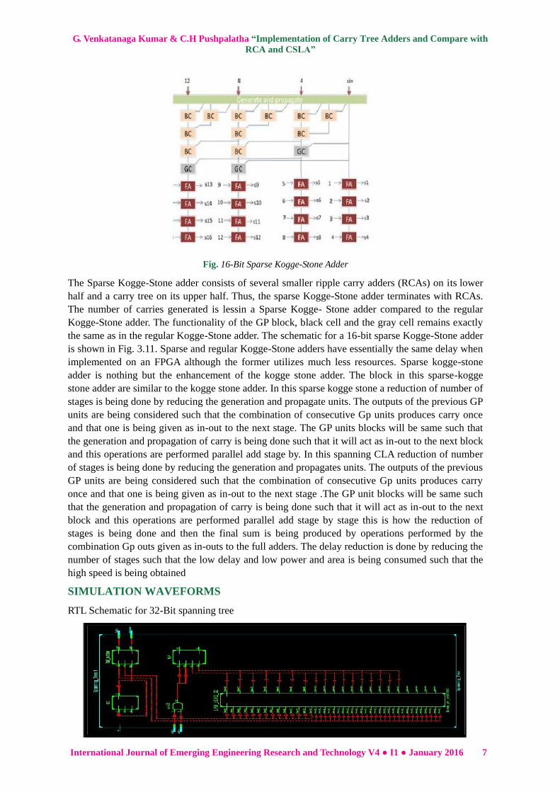
Fig. 16-Bit Sparse Kogge-Stone Adder
The Sparse Kogge-Stone adder consists of several smaller ripple carry adders (RCAs) on its lower
half and a carry tree on its upper half. Thus, the sparse Kogge-Stone adder terminates with RCAs.
The number of carries generated is lessin a Sparse Kogge- Stone adder compared to the regular
Kogge-Stone adder. The functionality of the GP block, black cell and the gray cell remains exactly
the same as in the regular Kogge-Stone adder. The schematic for a 16-bit sparse Kogge-Stone adder
is shown in Fig. 3.11. Sparse and regular Kogge-Stone adders have essentially the same delay when
implemented on an FPGA although the former utilizes much less resources. Sparse kogge-stone
adder is nothing but the enhancement of the kogge stone adder. The block in this sparse-kogge
stone adder are similar to the kogge stone adder. In this sparse kogge stone a reduction of number of
stages is being done by reducing the generation and propagate units. The outputs of the previous GP
units are being considered such that the combination of consecutive Gp units produces carry once
and that one is being given as in-out to the next stage. The GP units blocks will be same such that
the generation and propagation of carry is being done such that it will act as in-out to the next block
and this operations are performed parallel add stage by. In this spanning CLA reduction of number
of stages is being done by reducing the generation and propagates units. The outputs of the previous
GP units are being considered such that the combination of consecutive Gp units produces carry
once and that one is being given as in-out to the next stage .The GP unit blocks will be same such
that the generation and propagation of carry is being done such that it will act as in-out to the next
block and this operations are performed parallel add stage by stage this is how the reduction of
stages is being done and then the final sum is being produced by operations performed by the
combination Gp outs given as in-outs to the full adders. The delay reduction is done by reducing the
number of stages such that the low delay and low power and area is being consumed such that the
high speed is being obtained
SIMULATION WAVEFORMS
RTL Schematic for 32-Bit spanning tree

G. Venkatanaga Kumar & C.H Pushpalatha “Implementation of Carry Tree Adders and Compare with
RCA and CSLA”
8 International Journal of Emerging Engineering Research and Technology V4 ● I1 ● January 2016
Output for 32-Bit spanning tree:-
RTL Schematic for 64-Bit spanning tree:-
Output for 64 -Bit spanning tree:-
RTL Schematic for 128-Bit spanning tree:-
Output for128-Bit spanning tree:-
RTL Schematic for 32-Bit Ladner-Fischer:-

G. Venkatanaga Kumar & C.H Pushpalatha “Implementation of Carry Tree Adders and Compare with
RCA and CSLA”
International Journal of Emerging Engineering Research and Technology V4 ● I1 ● January 2016 9
Output for 32-Bit Ladner-Fischer:-
RTL Schematic for 64-Bit Ladner-Fischer:-
Output for 64-Bit Ladner-Fischer:-
RTL Schematic for 128-Bit Ladner-Fischer:-
Output for 128-Bit Ladner-Fischer:-
CONCLUSION
By the observations, conventional Ripple carry adder’s delay is doubled from 16-bit order to 128-bit
order where as in parallel prefix adders; the delay performance is changing slightly from low order
bits to higher order bits. Number of logic levels and number of LUTs are also increased with the
increased bit widths for all adders. But Spanning tree adder is maintaining nearly constant delay from
16-bit to 128-bit widths as well as number of LUTs and number of logic levels. From the results,
Spanning tree adder is performing better than conventional adders.

G. Venkatanaga Kumar & C.H Pushpalatha “Implementation of Carry Tree Adders and Compare with
RCA and CSLA”
10 International Journal of Emerging Engineering Research and Technology V4 ● I1 ● January 2016
REFERENCES
[1] V.Vijayalakshmil, R.Seshadd, Dr.S.Ramakrishnan3, Design and Implementation of 32 Bit
Unsigned Multiplier Using CLAA and CSLA, IEEE Trans. Comput., vol. C-31, pp. 260-264,
2013.
[2] N. H. E. Weste and D. Harris, CMOS VLSI Design, 4th edition, Pearson–Addison-Wesley, 2011.
[3] P. Ndai, S. Lu, D. Some sekhar, and K. Roy, “Fine-Grained Redundancy in Adders,” Int. Symp.
on Quality Electronic Design, pp. 317-321, March 2007.
[4] M. Bečvář and P. Štukjunger, “Fixed-Point Arithmetic in FPGA,” Acta Polytechnica, vol. 45, no.
2, pp. 67-72, 2005.
[5] D. Gizopoulos, M. Psarakis, A. Paschalis, and Y. Zorian, “Easily Testable Cellular Carry
Lookahead Adders,” Journal of Electronic Testing: Theory and Applications 19, 285-298, 2003.
[6] D. Harris, “A Taxonomy of Parallel Prefix Networks,” in Proc. 37th Asilomar Conf. Signals
Systems and Computers, pp. 2213–7, 2003.
[7] S. Xing and W. W. H. Yu, “FPGA Adders: Performance Evaluation and Optimal Design,” IEEE
Design & Test of Computers, vol. 15, no. 1, pp. 24-29, Jan. 1998.
[8] T. Lynch and E. E. Swartzlander, “A Spanning Tree Carry Lookahead Adder,” IEEE Trans. on
Computers, vol. 41, no. 8, pp. 931-939, Aug. 1992.
[9] R. P. Brent and H. T. Kung, “A regular layout for parallel adders,” IEEE Trans. Comput., vol. C-
31, pp. 260-264, 1982.
[10] A.Barenco, H. H. Bennett, R. Cleve, D. P. DiVinchenzo, N. Margolus, P. Shor, T. Sleator, J. A.
Smolin, and H. Weinfurter. Elementary gates for quantum computation. Physical Review A
(Atomic, Molecular, and Optical Physics), 52(5):3457–3467, 1995.
[11] B.H. Bennett. Logical reversibility of computation. Journal of IBM Research and Development,
17:525–532, 1961.
[12] R. Drechsler, A. Finder, and R. Wille. Improving ESOP-based synthesis of reversible logic using
evolutionary algorithms. In Proceedings of Intl. Conference on Applications of Evolutionary
Computation (Part II), pages 151–161, 2011.
[13] K. Fazel, M. A. Thornton, and J. Rice. ESOP-based Toffoli gate cascade generation. In
Proceedings of IEEE Pacific Rim Conference on Communications, Computers and Signal
Processing, pages 206–209, 2007.
[14] D. Grosse, R. Wille, G. W. Dueck, and R. Drechsler. Exact multiple control Toffoli network
synthesis with SAT techniques. IEEE Trans. on CAD of Integrated Circuits and Systems,
28(5):703–715, May 2009.
[15] W. N. N. Hung, X. Song, G. Yang, J. Yang, and M. Perkowski. Optimal synthesis of multiple
output boolean functions using a set of quantum gates by symbolic reachability analysis. IEEE
Trans. on CAD of Integrated Circuits and Systems, 25(9):1652–1663, September 2006.
[16] P. Kocher, J. Jaffe, and B. Jun. Differential power analysis. In
[17] Proceedings of Advances in Cryptology (CRYPTO ’99), LNCS Vol. 1666, pages 388–397, 1999.
[18] R. Landauer. Irreversibility and heat generation in computing process.
[19] Journal of IBM Research and Development, 5:183–191, 1961.
[20] D. M. Miller, D. Maslov, and G. W. Dueck. A transformation based algorithm for reversible logic
synthesis. In Proceedings of Design Automation Conference, pages 318–323, 2003.

G. Venkatanaga Kumar & C.H Pushpalatha “Implementation of Carry Tree Adders and Compare with
RCA and CSLA”
International Journal of Emerging Engineering Research and Technology V4 ● I1 ● January 2016 11
[21] A.Mishchenko and M. Perkowski. Fast heuristic minimization of exclusive-sums-of-products. In
Proceedings of 6th Reed-Muller Work-shop, pages 242–250, 2001.
[22] N. Nayeem, L. Jamal, and H. Babu. Efficient reversible Montgomery multiplier and its
applications to hardware cryptography. Journal of Computer Science, 5(1):49–56, January 2009.
[23] N. Nayeem and J. E. Rice. A shared-cube approach to ESOP-based
[24] synthesis of reversible logic. Facta Universitatis of NiE, Elec. Energ., 24(3):385–402, 2011.
[25] F. Rodriguez-Henriquez, N. Saqib, A. Perez, and C. Koc. Cryptographic Algorithms on
Reconfigurable Hardware. Springer: Series on Signals and Communication Technology, New
York, 2006.
[26] H. Thapliyal and M. Zwolinski. Reversible logic to cryptographic hardware: a new paradigm. In
Proceedings of 49th Midwest Symposium on Circuits and Systems (MWSCAS ’06), pages 342–
346, 2006.
[27] R. Wille and R. Drechsler. BDD-based synthesis of reversible logic for large functions. In
Proceedings of Design Automation Conference, pages 270–275, 2009
AUTHORS’ BIOGRAPHY
G.Venkatanaga Kumar, has received his B.Tech Degree in 2009 Electronics
and Instrumentation engineering from Vignan institute of technology and
science , Hyderabad and pursuing M.Tech in VLSI DESIGN from GONNA
INSTITUTE OF TECHNOLOGY Vishakhapatnam. His current area of research
includes Ladner-Fischer, Sparse kogge stone logics.
C.H Pushpalatha, has completed her B.Tech in 2011 Electronics and
communication engineering from NIE Guntur and completed her M.Tech in
AVANTHI INSTITUTE OF ENGINEERING AND TECHNOLOGY
Vishakhapatnam. Now working as an associate professor in GONNA
INSTITUTE OF TECHNOLOGY Vishakhapatnam.