
Impeller Volute and Diffuser Interaction - NATO Educational Notes/RTO-EN... · Impeller Volute and...
28
RTO-EN-AVT-143 6 - 1 Impeller Volute and Diffuser Interaction G. Pavesi Department of Mechanical Engineering University of Padova Via Venezia 1 Padova ITALY [email protected] 1. INTRODUCTION The flow in centrifugal pumps is exceedingly complex, involving curvature, system rotation, separation, turbulence, and secondary flows. Moreover, the geometry is often asymmetric due to the volute shape. As a result, the relative motion between impeller and volute generates an unstableness which affects not only the overall pump performance, but is also responsible for pressure fluctuations, hydraulic noises and unforeseen hydrodynamic forces. These fluctuations not only generate noise and vibration that cause unacceptable levels of stress and reduce component life due to fatigue, but also introduce unfavourable characteristics of pump performance even at or near the design point. Experimental and numerical approaches contributed to the understanding of the highly complex flow interactions that occur in a centrifugal pump. Binder et al. [1], Acosta et al. [2], and Stepanoff [3] conducted some of the earliest investigations on impeller forces in centrifugal pumps. Stepanoff proposed a simple empirical model based on impeller geometry, pump head and capacity to estimate the radial resultant forces. Agostinelli et al. [4] extended Stepanoff’s model taking to account the effect of specific speed on radial forces. Biheller [5] developed an equation to predict static radial pump forces applicable for a wide range of pump types and operating conditions. Hergt and Krieger [6], Kanki et al. [7] and Chamieh et al. [8] investigated the effects of single and double volute, vaned diffuser casing pumps and the influence of the impeller blades number on the hydrodynamic forces. More recently, de Ojeda et al. [9] combined the exit momentum flux and static pressure distributions around the impeller of a double volute pump to evaluate a total resultant radial thrust. A number of authors have treated the problem of the interaction of the impeller and its surroundings experimentally (Inoue and Cumpsty [10], Sideris and Braembussche [11] and Arndt et al. [12, 13]). Among others, a contribution to the understanding of the relation between unsteady flow and mechanical problems was the pressure measurements inside a high specific speed centrifugal impeller operating in a double spiral volute pump using piezoresistive pressure transducers and a telemetry system (Kaupert et al. [14]). Instead, Chu et al. [15–17] used particle image velocimetry complemented with noise and pressure measurements to measure the velocity distribution and compute the unsteady pressure field in the near- tongue region of the volute of a centrifugal pump. This pump was equipped with several different volutes having tongue gaps ranging from 7% to 28% of the impeller radius. The information available from PIV contributed to a better understanding of the flow in centrifugal machines and to observe and study the influence of the blade passing in front of the volute tongue addressing both flow structure and turbulence modelling issues. Pavesi, G. (2006) Impeller Volute and Diffuser Interaction. In Design and Analysis of High Speed Pumps (pp. 6-1 – 6-28). Educational Notes RTO-EN-AVT-143, Paper 6. Neuilly-sur-Seine, France: RTO. Available from: http://www.rto.nato.int/abstracts.asp.
Transcript of Impeller Volute and Diffuser Interaction - NATO Educational Notes/RTO-EN... · Impeller Volute and...
RTO-EN-AVT-143 6 - 1
Impeller Volute and Diffuser Interaction
G. Pavesi Department of Mechanical Engineering
University of Padova Via Venezia 1
Padova ITALY
1. INTRODUCTION
The flow in centrifugal pumps is exceedingly complex, involving curvature, system rotation, separation, turbulence, and secondary flows. Moreover, the geometry is often asymmetric due to the volute shape. As a result, the relative motion between impeller and volute generates an unstableness which affects not only the overall pump performance, but is also responsible for pressure fluctuations, hydraulic noises and unforeseen hydrodynamic forces. These fluctuations not only generate noise and vibration that cause unacceptable levels of stress and reduce component life due to fatigue, but also introduce unfavourable characteristics of pump performance even at or near the design point. Experimental and numerical approaches contributed to the understanding of the highly complex flow interactions that occur in a centrifugal pump.
Binder et al. [1], Acosta et al. [2], and Stepanoff [3] conducted some of the earliest investigations on impeller forces in centrifugal pumps. Stepanoff proposed a simple empirical model based on impeller geometry, pump head and capacity to estimate the radial resultant forces. Agostinelli et al. [4] extended Stepanoff’s model taking to account the effect of specific speed on radial forces. Biheller [5] developed an equation to predict static radial pump forces applicable for a wide range of pump types and operating conditions. Hergt and Krieger [6], Kanki et al. [7] and Chamieh et al. [8] investigated the effects of single and double volute, vaned diffuser casing pumps and the influence of the impeller blades number on the hydrodynamic forces. More recently, de Ojeda et al. [9] combined the exit momentum flux and static pressure distributions around the impeller of a double volute pump to evaluate a total resultant radial thrust.
A number of authors have treated the problem of the interaction of the impeller and its surroundings experimentally (Inoue and Cumpsty [10], Sideris and Braembussche [11] and Arndt et al. [12, 13]).
Among others, a contribution to the understanding of the relation between unsteady flow and mechanical problems was the pressure measurements inside a high specific speed centrifugal impeller operating in a double spiral volute pump using piezoresistive pressure transducers and a telemetry system (Kaupert et al. [14]).
Instead, Chu et al. [15–17] used particle image velocimetry complemented with noise and pressure measurements to measure the velocity distribution and compute the unsteady pressure field in the near-tongue region of the volute of a centrifugal pump. This pump was equipped with several different volutes having tongue gaps ranging from 7% to 28% of the impeller radius. The information available from PIV contributed to a better understanding of the flow in centrifugal machines and to observe and study the influence of the blade passing in front of the volute tongue addressing both flow structure and turbulence modelling issues.
Pavesi, G. (2006) Impeller Volute and Diffuser Interaction. In Design and Analysis of High Speed Pumps (pp. 6-1 – 6-28). Educational Notes RTO-EN-AVT-143, Paper 6. Neuilly-sur-Seine, France: RTO. Available from: http://www.rto.nato.int/abstracts.asp.
Impeller Volute and Diffuser Interaction
6 - 2 RTO-EN-AVT-143
Paone et al. [18] at VKI used particle image velocimetry to measure the flow field inside the vaneless diffuser of a centrifugal shrouded pump. They compared the PIV measurements and the corresponding LDV measurement data and found that they were different in the wake.
In addition to experimental investigations, numerous analytical studies were undertaken to predict the radial hydraulic forces in centrifugal pumps, Domm and Hergt [19], Lorett and Gopalakrishnan [20], and Fongang et al. [21] to name only a few.
Some of the studies, e.g., Hillewaert and Van den Braembussche [22], considered the flow as inviscid and some authors, e.g., Longatte and Kueny [23], use a two-dimensional model. Improved computational algorithms as well as hardware development have contributed to enhance CFD capability. It is now feasible to use CFD codes for a realistic prediction of the complex three-dimensional turbulent flow in the entire pump and perform unsteady calculations see, for example, Zhang et al. [24] and Gonza´lez et al. [25, 26].
In a diffuser pump, the centrifugal impeller interferes with its successive diffuser vanes and produces pressure fluctuations downstream of the impeller. In the case of a small radial gap between the impeller and diffuser vanes, the magnitude of these pressure fluctuations may become as large as the total pressure rise across the pump (Arndt et al., [27, 28]; and Tsukamoto et al. [29]). Dring et al. [30] indicated two distinct mechanisms of rotor-stator interaction: (I) wake interactions and (II) potential interactions. Potential interactions are induced by inviscid interaction due to the relative motion between rotor blades and stator vanes. Wake interaction originated from the impingement and convection of wakes shed from the impeller passages and moving through the successive diffuser passages. Some experimental contributions to wake interactions in pumps may be attributed to the extensive PIV measurements by Dong et al. [31], and Akin et al. [32] G. Wuibaut et all [33], and hot wire measurement by Ubaldi et al. [34].
However, it is difficult to understand the flow phenomena due to impeller diffuser interaction from only experimental studies because of the complicated flow structures in centrifugal pumps. Qin and Tsukamoto [34] calculated an unsteady flow caused by impeller diffuser interaction in a diffuser pump with a singularity method. Following their works, Shi and Tsukamoto [35] calculated the pressure fluctuations downstream of the diffuser pump impeller using two-dimensional and three-dimensional unsteady RANS code with standard k-ε turbulence models. Wang and Tsukamoto [36] used an advanced vortex method to calculate the impeller-diffuser interaction, in which the changing operating points of pump were taken into account.
Unsteady phenomena in diffuser pumps become more complicated at off-design operating conditions. At reduced flow rates, the flow rate and pressure of a pump become increasingly unstable. When substantial flow fluctuations are propagating at a low frequency along the circumference, but are limited to a part of the components (e.g., rotor, diffuser, or volute), the phenomenon is typically referred to as rotating stall. Yoshida et al. [37] investigated the rotating stall instability in a seven-bladed centrifugal impeller with a variety of diffusers.
However, the knowledge about the unsteady pressure fluctuations and the unsteady blade loading is still not satisfying. Furthermore, the design of the centrifugal pumps has already reached a level that only through a detailed understanding of the internal flow an increase of the overall performance can be achieved. Due to the curved passages inside the impeller and the volute the flow is to be considered as three-dimensional. Additionally, since the flow following blade passages as well as the volute casing interacts with viscous boundary layers, secondary flows are generated. Therefore, a correct simulation of the impeller/volute interaction requires the simultaneous solution of the three-dimensional unsteady Navier-Stokes equations in both the impeller and volute.

Impeller Volute and Diffuser Interaction
RTO-EN-AVT-143 6 - 3
2. NOMENCLATURE
A area b width p pressure C Absolute Velocity
( ) ( )2CppCp 222 ρ−= pressure coefficient
Cu absolute tangential velocity Cm absolute meridional velocity g gravity acceleration Hin input head h0 Busemann’s head coefficient Q flow rate r radius U peripheral velocity ηv volumetric efficiency ρ density ζ blockage coefficient θ circumferential coordinate Subscripts 1 at impeller inlet 2 at impeller outlet
3. VOLUTE
In a turbomachine the impeller does all the work while the volute appears merely to collect the flow from the runner and guide it to the discharge.
It is, however, wrong to conclude that the two parts operate independently of each other. The pump volute determines the surroundings in which the impeller operates, and it can have a profound effect on impeller performance and can cause the impeller to work inefficiently.
The impeller of a centrifugal pump can be simply regarded as a source of radial flow on which is superimposed a vortex. Therefore, the flow emerges from the outlet with a spiral path whose circumferential components of velocity is related to the head, while the meridional component is related to the flow rate. Thus, the angle of the spiral flow depends on the point of operation on the impeller characteristic.
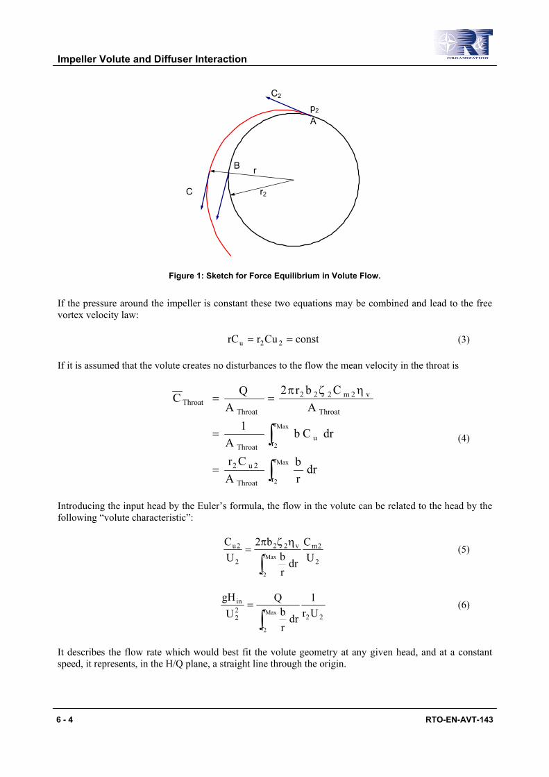
It can easily be shown that the pressure around the impeller is uniform only when there is a free vortex velocity distribution in the volute. For a perfect fluid the pressure in all the points on a streamline emerging from the impeller (fig. 1) is related to the pressure at the impeller outlet by Bernoulli’s equation:
222
2 C21pC
21p ρ+=ρ+ (1)
and to the pressure at B (fig. 1) by the equation of radial forces:
r
Cdrdp 2
ρ= (2)
Impeller Volute and Diffuser Interaction
6 - 4 RTO-EN-AVT-143
Ap2
C2
r2
rB
C
Figure 1: Sketch for Force Equilibrium in Volute Flow.
If the pressure around the impeller is constant these two equations may be combined and lead to the free vortex velocity law:
constCurrC 22u == (3)
If it is assumed that the volute creates no disturbances to the flow the mean velocity in the throat is
∫
∫=
=
ηζπ==
Max
2
Max
2
r
rThroat
2u2
r
ru
Throat
Throat
v2m222
ThroatThroat
drrb
ACr
drCbA
1A
Cbr2A
QC
(4)
Introducing the input head by the Euler’s formula, the flow in the volute can be related to the head by the following “volute characteristic”:
2
2mr
r
v22
2
2u
UC
drrb
b2UC
Max
2∫
ηζπ= (5)
22
r
r
22
in
Ur1
drrb
QU
gHMax
2∫
= (6)
It describes the flow rate which would best fit the volute geometry at any given head, and at a constant speed, it represents, in the H/Q plane, a straight line through the origin.

Impeller Volute and Diffuser Interaction
RTO-EN-AVT-143 6 - 5
The pump impeller has also a characteristic relating input head to flow:
β
ηζπ−= b2
2v22202
2
in cotUbr2
QhU
gH (7)
and the intersection point of the two is the only one that satisfies the requirement of both the impeller and the volute.
Any departure from this condition produces in the volute circumferential pressure gradients at the impeller periphery so that the flow in each blade passage pulsates as the impeller rotates in the volute. This causes a variation in the total head generates, a subsequent mixing of different total energy streams with energy losses and flow separation at the cutwater and reverse flow from the volute back into the impeller may take place.
For evaluating the impeller volute interaction, a shrouded pump with an outlet radius of 167 mm, an outlet with of 8 mm, and seven blades with a 22.5 deg outlet lean angle, measured from the radial direction, will be considered. The single volute casing is vaneless. The shape of the volute casing was designed according to the theory of a constant average velocity for all sections of the volute. (fig. 2). The gap between the tongue and the volute inner wall was 7 mm and extended over the whole volute.
Figure 2: Pump Geometry.
The coupling influence on the reference pump is illustrate in fig. 3, which shows mean local streamline patterns for three different flow rate.

Impeller Volute and Diffuser Interaction
6 - 6 RTO-EN-AVT-143
(a) 53% QDes (b) 100% QDes (c) 135% QDes
Figure 3: Streamline Patterns.
When the spiral path matches the volute spiral, as in fig. 3b, there was little flow disturbance at the impeller radius in spite of the sudden deflection into the discharge branch.
At lower and higher flow rate the deflection at the cutwater caused severe energy losses and was responsible of the radial thrust on pump impeller.
In fig. 4 the measured mean static pressure and the average numerical data are shown for the volute design flow rate.
-0.2
-0.1
0.0
0.1
0.2
0.3
0.4
0.5
0.6
0.7
0.8
-40 0 40 80 120 160 200 240 280 320 360
θ [°]
(P-P
2)/( ρ
C2^
2/2)
[-]
Q/QDes=100%Experimental
Figure 4: Numerical and Experimental Pressure Variation around Volute 100% QDes.
The mean pressure distribution around the volute was not exactly uniform even at the design flow rate. The variation was limited to a sudden upward spike just before the cutwater and a corresponding downward one just after it. The sudden jump was unavoidable with a tongue of finite thickness and it was also amplified, in this volute, by the curvature of the outlet branch.
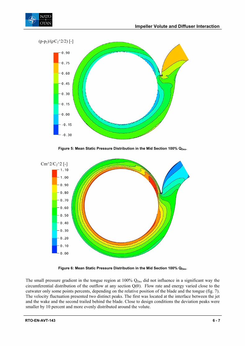
The static and dynamic pressure distribution around the periphery of the impeller (figs 5 and 6) reflected this dissymmetry.
Impeller Volute and Diffuser Interaction
RTO-EN-AVT-143 6 - 7
(p-p2)/(ρC2^2/2) [-]
Figure 5: Mean Static Pressure Distribution in the Mid Section 100% QDes.
Cm^2/C2^2 [-]
Figure 6: Mean Static Pressure Distribution in the Mid Section 100% QDes.
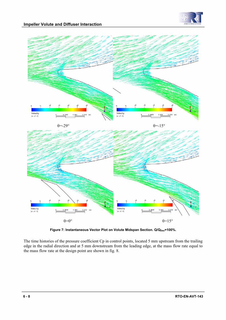
The small pressure gradient in the tongue region at 100% QDes did not influence in a significant way the circumferential distribution of the outflow at any section Q(θ). Flow rate and energy varied close to the cutwater only some points percents, depending on the relative position of the blade and the tongue (fig. 7). The velocity fluctuation presented two distinct peaks. The first was located at the interface between the jet and the wake and the second trailed behind the blade. Close to design conditions the deviation peaks were smaller by 10 percent and more evenly distributed around the volute.
Impeller Volute and Diffuser Interaction
6 - 8 RTO-EN-AVT-143
θ=-29° θ=-15°
θ=0° θ=15°
Figure 7: Instantaneous Vector Plot on Volute Midspan Section. Q/QDes=100%.
The time histories of the pressure coefficient Cp in control points, located 5 mm upstream from the trailing edge in the radial direction and at 5 mm downstream from the leading edge, at the mass flow rate equal to the mass flow rate at the design point are shown in fig. 8.

Impeller Volute and Diffuser Interaction
RTO-EN-AVT-143 6 - 9
-0.1
0.0
0.1
0.2
0.3
0.4
0.5
0 50 100 150 200 250 300 350 400 450 500Time [ms]
(p-p
0)/ ρ
/U2^
2 [-
]
2P
2S
1P
1S
Figure 8: The Time Histories of the Pressure Coefficient 100% QDes.
At the impeller outlet due to the interaction between the impeller blades and the tongue of the volute casing, amplitudes of pressure fluctuation can be observed. Since the flow is incompressible, pressure fluctuations at the impeller outlet caused by the interaction between the blades and tongue of the volute casing, was reflected upstream to the impeller inlet (fig. 8). It can be seen that the amplitude of the pressure fluctuations within the impeller passage grows in magnitude as the trailing edge of the blade was approached. Comparing the pressure fluctuations at the pressure side (nodal points 1P-2P) with suction side (nodal points 1S-2S) reveals that the amplitude of the pressure fluctuations on the pressure side of the blade passage was larger than on the suction side. Due to the limited interaction between the impeller blades and the tongue the deviation peaks at inlet, concentrated near the blades faced with the tongue, are negligible (figs 8 and 9).
Impeller Volute and Diffuser Interaction
6 - 10 RTO-EN-AVT-143
θ=-29° θ=-22° θ=-15°
θ=0° θ=7° θ=15°
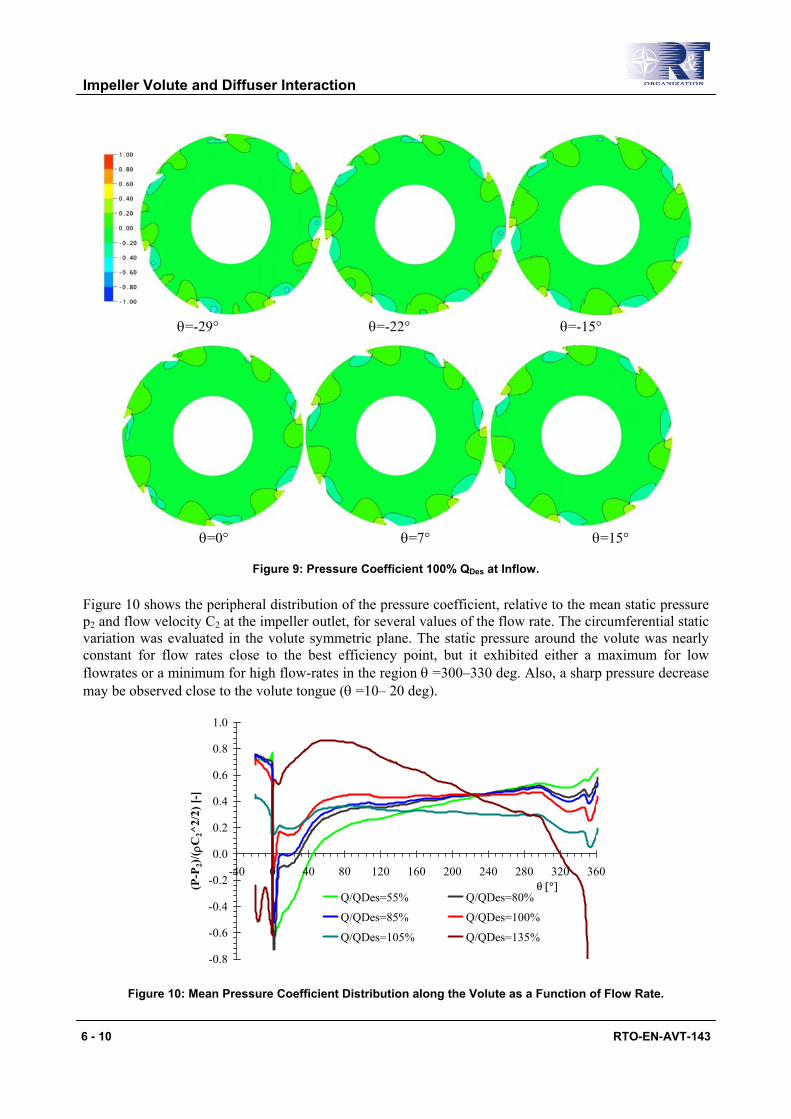
Figure 9: Pressure Coefficient 100% QDes at Inflow.
Figure 10 shows the peripheral distribution of the pressure coefficient, relative to the mean static pressure p2 and flow velocity C2 at the impeller outlet, for several values of the flow rate. The circumferential static variation was evaluated in the volute symmetric plane. The static pressure around the volute was nearly constant for flow rates close to the best efficiency point, but it exhibited either a maximum for low flowrates or a minimum for high flow-rates in the region θ =300–330 deg. Also, a sharp pressure decrease may be observed close to the volute tongue (θ =10– 20 deg).
-0.8
-0.6
-0.4
-0.2
0.0
0.2
0.4
0.6
0.8
1.0
-40 0 40 80 120 160 200 240 280 320 360θ [°](P
-P2)
/( ρC
2^2/
2) [-
]
Q/QDes=55% Q/QDes=80%
Q/QDes=85% Q/QDes=100%
Q/QDes=105% Q/QDes=135%
Figure 10: Mean Pressure Coefficient Distribution along the Volute as a Function of Flow Rate.
Impeller Volute and Diffuser Interaction
RTO-EN-AVT-143 6 - 11
These no uniform pressure distributions were related to the acceleration (high flow-rates) or deceleration (low flow-rates) of the flow along the volute for off-design conditions.
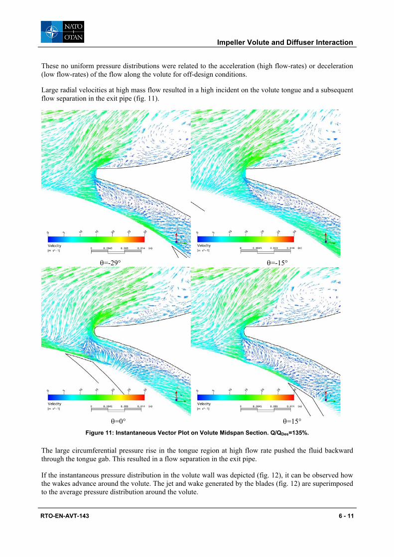
Large radial velocities at high mass flow resulted in a high incident on the volute tongue and a subsequent flow separation in the exit pipe (fig. 11).
θ=-29° θ=-15°
θ=0° θ=15°
Figure 11: Instantaneous Vector Plot on Volute Midspan Section. Q/QDes=135%.
The large circumferential pressure rise in the tongue region at high flow rate pushed the fluid backward through the tongue gab. This resulted in a flow separation in the exit pipe.
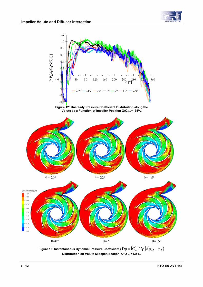
If the instantaneous pressure distribution in the volute wall was depicted (fig. 12), it can be observed how the wakes advance around the volute. The jet and wake generated by the blades (fig. 12) are superimposed to the average pressure distribution around the volute.
Impeller Volute and Diffuser Interaction
6 - 12 RTO-EN-AVT-143
-0.8
-0.6
-0.4
-0.2
0.0
0.2
0.4
0.6
0.8
1.0
1.2
-40 0 40 80 120 160 200 240 280 320 360θ [°](P
-P2)
/( ρC
2^2/
2) [-
]
-22° -15° -7° 0° 7° 15° -29°
Figure 12: Unsteady Pressure Coefficient Distribution along the
Volute as a Function of Impeller Position Q/QDes=135%.
θ=-29° θ=-22° θ=-15°
θ=0° θ=7° θ=15°
Figure 13: Instantaneous Dynamic Pressure Coefficient ( ( ) ( )22o2m pp/2/CDp −ρ=
Distribution on Volute Midspan Section. Q/QDes=135%.
Impeller Volute and Diffuser Interaction
RTO-EN-AVT-143 6 - 13
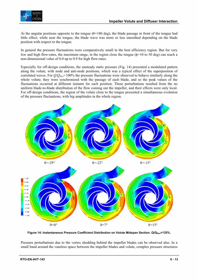
At the angular positions opposite to the tongue (θ=180 deg), the blade passage in front of the tongue had little effect, while near the tongue, the blade wave was more or less smoothed depending on the blade position with respect to the tongue.
In general the pressure fluctuations were comparatively small in the best efficiency region. But for very low and high flow-rates, the maximum range, in the region close the tongue (φ=10 to 50 deg) can reach a non-dimensional value of 0.0 up to 0.9 for high flow-rates.
Especially for off-design conditions, the unsteady static pressure (Fig. 14) presented a modulated pattern along the volute, with node and anti-node positions, which was a typical effect of the superposition of correlated waves. For Q/QDes=100% the pressure fluctuations were observed to behave similarly along the whole volute; they were synchronized with the passage of each blade, and so the peak values of the fluctuations occurred at different instants for each position. These perturbations resulted from the no uniform blade-to-blade distribution of the flow coming out the impeller, and their effects were only local. For off-design conditions, the region of the volute close to the tongue presented a simultaneous evolution of the pressure fluctuations, with big amplitudes in the whole region.
θ=-29° θ=-22° θ=-15°
θ=0° θ=7° θ=15°
Figure 14: Instantaneous Pressure Coefficient Distribution on Volute Midspan Section. Q/QDes=135%.
Pressure perturbations due to the vortex shedding behind the impeller blades can be observed also. In a small band around the vaneless space between the impeller blades and volute, complex pressure structures
Impeller Volute and Diffuser Interaction
6 - 14 RTO-EN-AVT-143
can be observed. These pressure structures were well correlated with the unsteady part of the relative velocity at the exit of the impeller.
Outside this band, the pressure field was smoother and it can be observed that the pressure unsteadiness in the impeller was well synchronized. These global pressure variations were due to potential effects. Potential interactions were induced by inviscid interaction due to the relative motion between rotor blades and stator.
Indeed, the pressure pulsations around the impeller outlet and volute inlet were the result of the strong interaction between the blades and the tongue. Comparing the results for flow-rates above and below QDes, the fluctuations in the region close to the tongue were seen to be shifted 180 deg from each other. This was related to the shift of the stagnation point on the tongue and the different characteristics of the recirculation flow through the gap. For low flow-rates the alignment of the blades with the tongue coincides with a positive value of the pressure, whereas it coincided with a negative value for the high flow-rates. Therefore, the unsteady pressure in the volute resulted from the combination of: (I) the jet-wake pattern associated to the continuous blade rotation around the volute, and (II) the intermittent interaction of those disturbances and the volute tongue.
Wake interaction originated from the impingement and convection of wakes shed from the impeller passages.
With advancement of the pressure fluctuations were damped, as it can be seen from Figures 13 and 14, in a cross sectional plane of the casing at angular advancement φ =260°, the pressure fluctuations were small. In this cross-sectional plane, the pressure gradients had only one island (part I) and correspondingly the secondary flow has only one vortex (part II).
Both sources can be initially considered totally independent, with no relationship between their locations in the volute, amplitudes or relative phase delay: the only common feature was to radiate harmonic sound at the blade passing frequency.
The two sources can be reasonably simulated by a dipole, with amplitude that increased fast when diverging from the best-efficiency flow-rate. The positive or negative combination of that sound field with the fluctuations associated to the continuous rotation of the blades leads to the modulated pattern in the pressure amplitude suggested by Fig. 12 for off-design conditions.
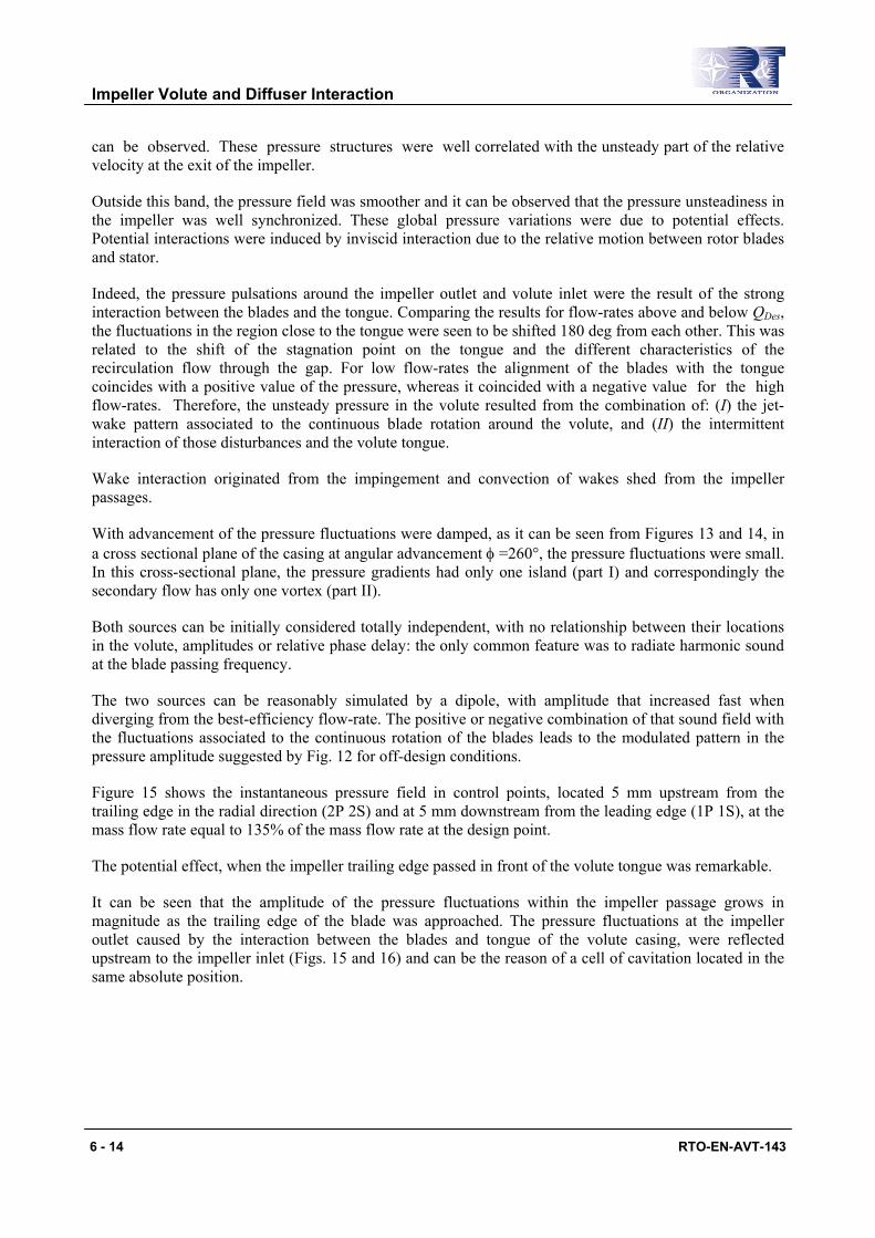
Figure 15 shows the instantaneous pressure field in control points, located 5 mm upstream from the trailing edge in the radial direction (2P 2S) and at 5 mm downstream from the leading edge (1P 1S), at the mass flow rate equal to 135% of the mass flow rate at the design point.
The potential effect, when the impeller trailing edge passed in front of the volute tongue was remarkable.
It can be seen that the amplitude of the pressure fluctuations within the impeller passage grows in magnitude as the trailing edge of the blade was approached. The pressure fluctuations at the impeller outlet caused by the interaction between the blades and tongue of the volute casing, were reflected upstream to the impeller inlet (Figs. 15 and 16) and can be the reason of a cell of cavitation located in the same absolute position.
Impeller Volute and Diffuser Interaction
RTO-EN-AVT-143 6 - 15
-0.1
0.0
0.1
0.2
0.3
0.4
0.5
0 50 100 150 200 250 300 350 400 450 500Time [ms]
(p-p
0)/ ρ
/U2^
2 [-
]
2P
2S
1P
1S
Figure 15: The Time Histories of the Pressure Coefficient 135% QDes.
θ=-29° θ=-22° θ=-15°
θ=0° θ=7° θ=15°
Figure 16: Instantaneous Pressure Coefficient Distribution at Inflow Q/QDes=135%.
Impeller Volute and Diffuser Interaction
6 - 16 RTO-EN-AVT-143
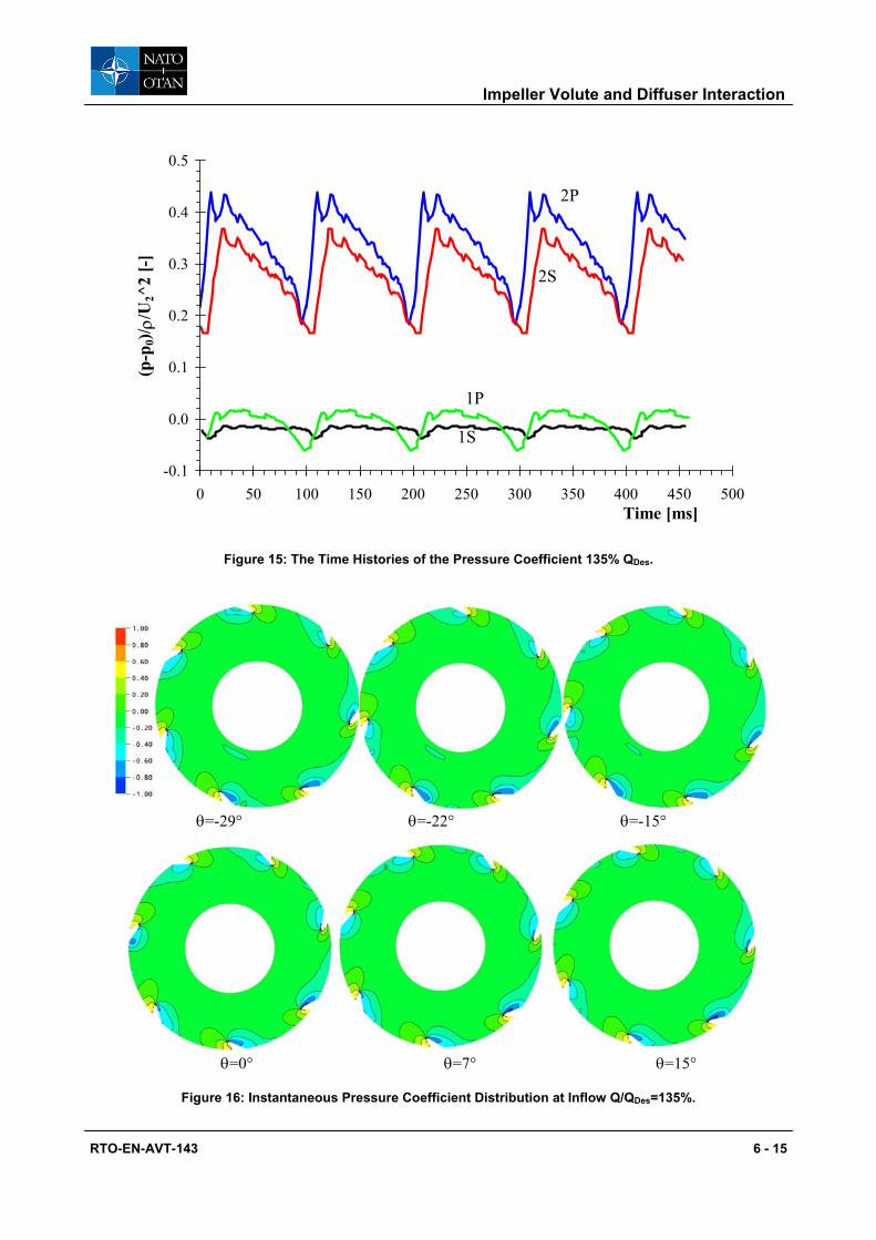
Pressure fluctuations at the impeller inlet and outlet influenced the mass flow rate through the blade passages. The mass flow rate through each blade passage varied with time according to the relative position of the blade passage to the tongue of the volute casing for off-design conditions. The periodic pressure distribution at the impeller-inlet and outlet leaded to a periodic flow, which resulted in a cyclic acceleration and deceleration of the fluid flow inside each blade passage (Fig. 17).
-80
-60
-40
-20
0
20
40
60
-15 -10 -5 0 5 10 15 20 25Flow Rate %
Tot
al P
ress
ure
%
-29° -22°
-15° -7°
0° 7°
15°
Blade to Blade passage faced with tongue
Figure 17: Instantaneous Deviation from the Mean Flow Rate and Total Pressure Elaborated by Each Blade Channel Q/QDes=135%.
The diagram shows wide variation of the mass and total pressure values. Near at best efficiency point the circumferential distribution of static pressure tended to be uniform and hence has very little or no effect on the impeller flow. Therefore at this operating point, the circumferential distribution of total pressure, flow angle, and total pressure was unaffected and also remained uniform, which suggested quite a rotational symmetric flow pattern.
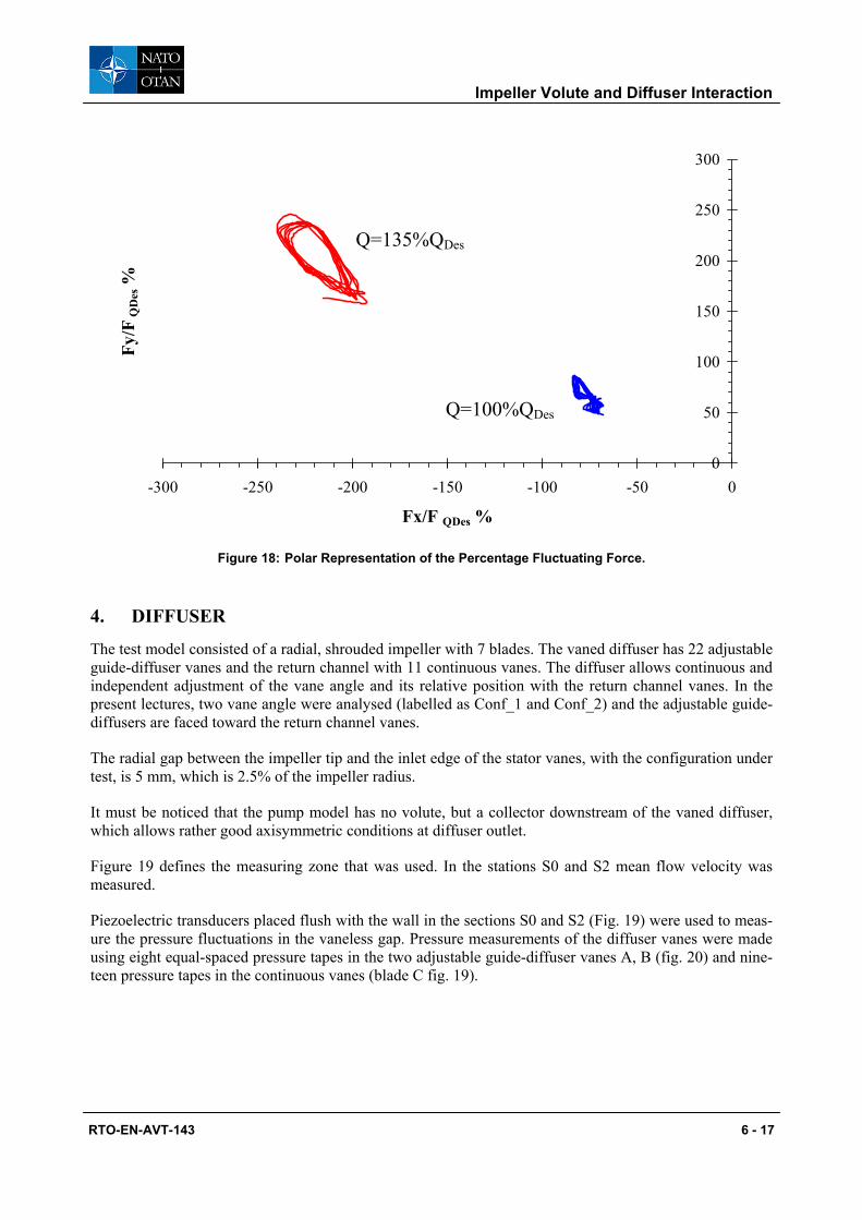
The fluctuating pressure field gave rise to dynamic forces which can cause fatigue failure of the pump axis (especially at off-design operating conditions). An example of such effects can be seen in Fig. 18 where the percentage modulus of the fluctuating force is plotted in polar. Very large differences of the forces resulted for the smallest and for the largest volume flow of the pump. At flow rates in the proximity of the best efficiency point substantially smaller force differences arose. The fact that the curve paths are not closed is related to the build-up process of the transient flow solution which was not yet fully periodic.
Impeller Volute and Diffuser Interaction
RTO-EN-AVT-143 6 - 17
0
50
100
150
200
250
300
-300 -250 -200 -150 -100 -50 0
Fx/F QDes %
Fy/F
QD
es %
Figure 18: Polar Representation of the Percentage Fluctuating Force.
4. DIFFUSER
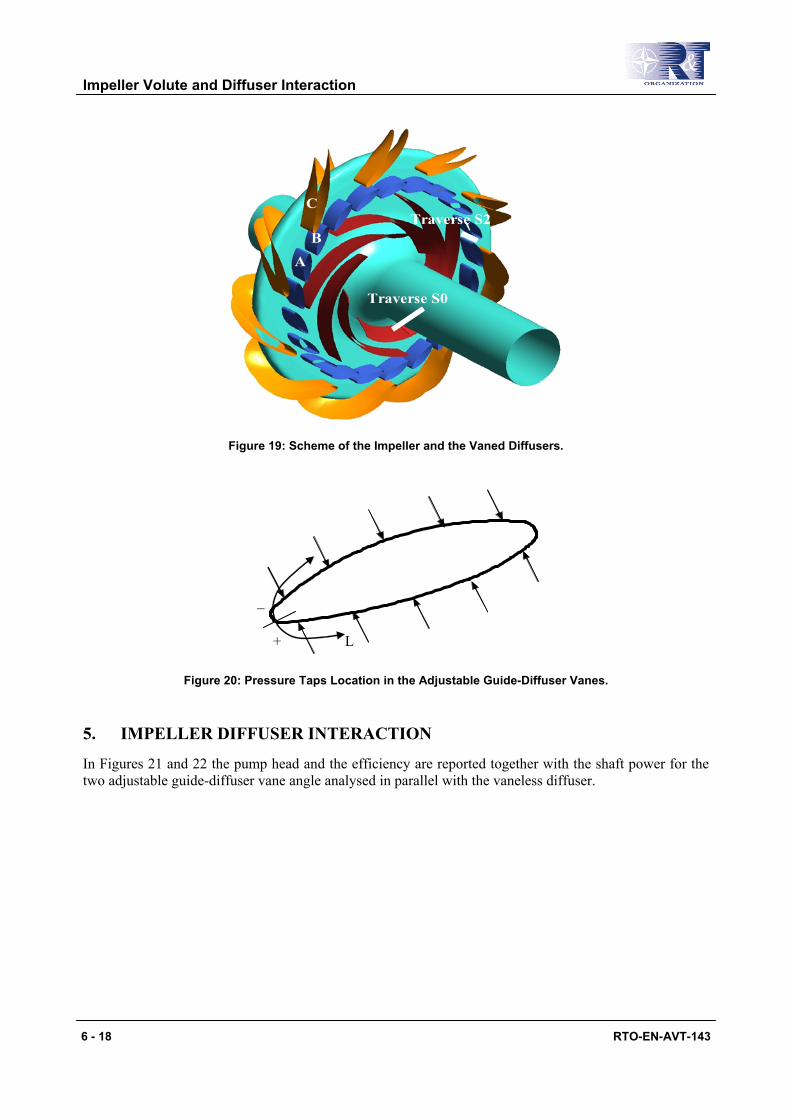
The test model consisted of a radial, shrouded impeller with 7 blades. The vaned diffuser has 22 adjustable guide-diffuser vanes and the return channel with 11 continuous vanes. The diffuser allows continuous and independent adjustment of the vane angle and its relative position with the return channel vanes. In the present lectures, two vane angle were analysed (labelled as Conf_1 and Conf_2) and the adjustable guide-diffusers are faced toward the return channel vanes.
The radial gap between the impeller tip and the inlet edge of the stator vanes, with the configuration under test, is 5 mm, which is 2.5% of the impeller radius.
It must be noticed that the pump model has no volute, but a collector downstream of the vaned diffuser, which allows rather good axisymmetric conditions at diffuser outlet.
Figure 19 defines the measuring zone that was used. In the stations S0 and S2 mean flow velocity was measured.
Piezoelectric transducers placed flush with the wall in the sections S0 and S2 (Fig. 19) were used to meas-ure the pressure fluctuations in the vaneless gap. Pressure measurements of the diffuser vanes were made using eight equal-spaced pressure tapes in the two adjustable guide-diffuser vanes A, B (fig. 20) and nine-teen pressure tapes in the continuous vanes (blade C fig. 19).
Q=135%QDes
Q=100%QDes
Impeller Volute and Diffuser Interaction
6 - 18 RTO-EN-AVT-143
Traverse S0
Traverse S2
A
B
C
Figure 19: Scheme of the Impeller and the Vaned Diffusers.
L +
_
Figure 20: Pressure Taps Location in the Adjustable Guide-Diffuser Vanes.
5. IMPELLER DIFFUSER INTERACTION
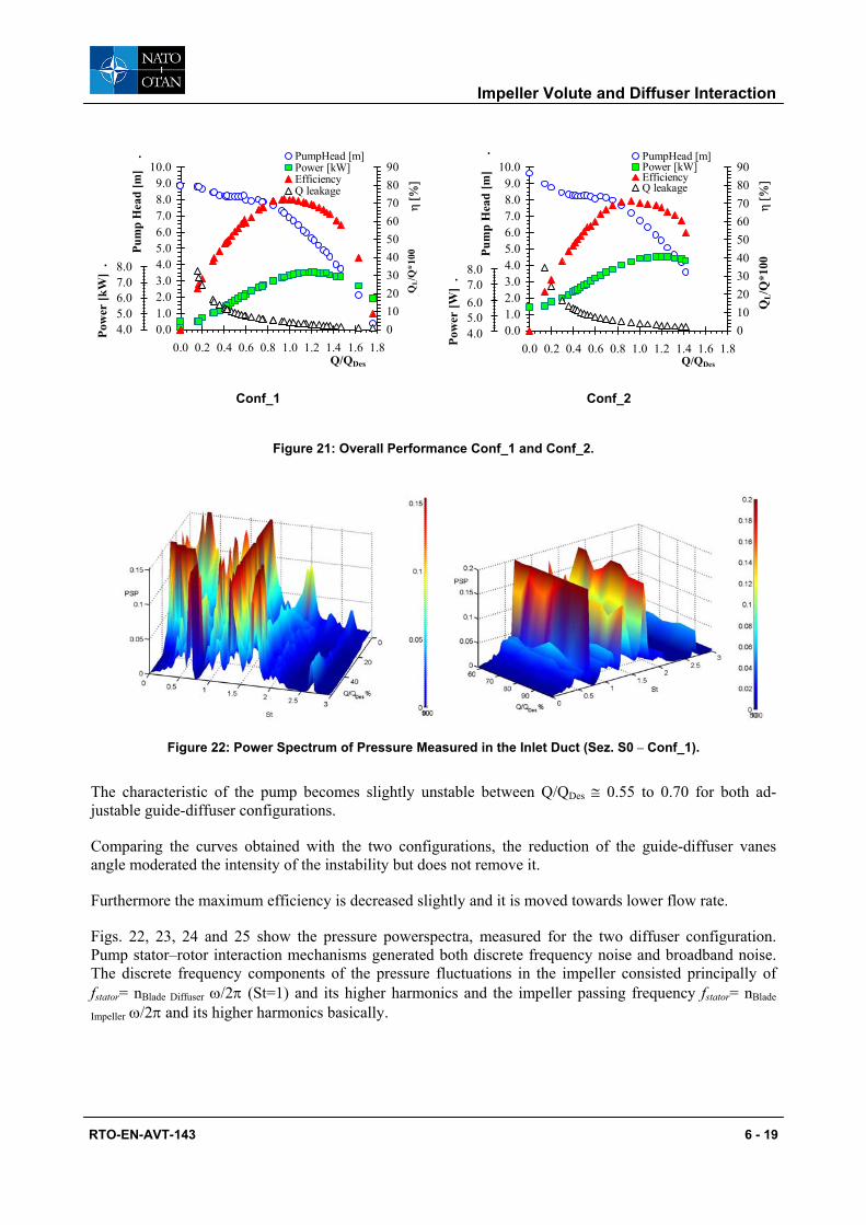
In Figures 21 and 22 the pump head and the efficiency are reported together with the shaft power for the two adjustable guide-diffuser vane angle analysed in parallel with the vaneless diffuser.
Impeller Volute and Diffuser Interaction
RTO-EN-AVT-143 6 - 19
0.01.02.03.04.05.06.07.08.09.0
10.0
0.0 0.2 0.4 0.6 0.8 1.0 1.2 1.4 1.6 1.8Q/QDes
Pum
p H
ead
[m]
.
0102030405060708090
η [
%]
PumpHead [m]Power [kW]EfficiencyQ leakage
7.08.0
6.05.04.0Po
wer
[kW
] .
QL/Q
*100
0.01.02.03.04.05.06.07.08.09.0
10.0
0.0 0.2 0.4 0.6 0.8 1.0 1.2 1.4 1.6 1.8Q/QDes
Pum
p H
ead
[m]
.
0102030405060708090
η [
%]
PumpHead [m]Power [kW]EfficiencyQ leakage
QL/Q
*100
7.08.0
6.05.04.0Po
wer
[W]
.
Conf_1 Conf_2
Figure 21: Overall Performance Conf_1 and Conf_2.
Figure 22: Power Spectrum of Pressure Measured in the Inlet Duct (Sez. S0 – Conf_1).
The characteristic of the pump becomes slightly unstable between Q/QDes ≅ 0.55 to 0.70 for both ad-justable guide-diffuser configurations.
Comparing the curves obtained with the two configurations, the reduction of the guide-diffuser vanes angle moderated the intensity of the instability but does not remove it.
Furthermore the maximum efficiency is decreased slightly and it is moved towards lower flow rate.
Figs. 22, 23, 24 and 25 show the pressure powerspectra, measured for the two diffuser configuration. Pump stator–rotor interaction mechanisms generated both discrete frequency noise and broadband noise. The discrete frequency components of the pressure fluctuations in the impeller consisted principally of fstator= nBlade Diffuser ω/2π (St=1) and its higher harmonics and the impeller passing frequency fstator= nBlade
Impeller ω/2π and its higher harmonics basically.

Impeller Volute and Diffuser Interaction
6 - 20 RTO-EN-AVT-143
Figure 23: Power Spectrum of Pressure Measured in the Inlet Diffuser (Sez. S2 –Conf_1).
Figure 24: Power Spectrum of Pressure Measured in the Inlet Duct (Sez. S0 – Conf_2).
Figure 25: Power Spectrum of Pressure Measured in the Inlet Diffuser (Sez. S2 – Conf_2).
The broadband component was associated with the turbulent flow. Noise was generated as the inertia of vortical disturbances was modified. This occurred essentially due to the sudden change in the boundary conditions applied to the vorticity as vortices interact with solid boundary.
Impeller Volute and Diffuser Interaction
RTO-EN-AVT-143 6 - 21
At high flow rates the spectral shape was very similar for each discharge configuration suggesting that the dominant type of pressure mechanism did not change significantly with modifications to the impeller dis-charge configuration.
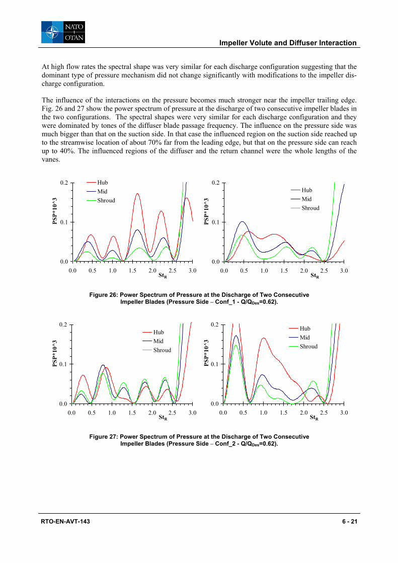
The influence of the interactions on the pressure becomes much stronger near the impeller trailing edge. Fig. 26 and 27 show the power spectrum of pressure at the discharge of two consecutive impeller blades in the two configurations. The spectral shapes were very similar for each discharge configuration and they were dominated by tones of the diffuser blade passage frequency. The influence on the pressure side was much bigger than that on the suction side. In that case the influenced region on the suction side reached up to the streamwise location of about 70% far from the leading edge, but that on the pressure side can reach up to 40%. The influenced regions of the diffuser and the return channel were the whole lengths of the vanes.
0.0
0.1
0.2
0.0 0.5 1.0 1.5 2.0 2.5 3.0StR
PSP*
10^3
HubMidShroud
0.0
0.1
0.2
0.0 0.5 1.0 1.5 2.0 2.5 3.0StR
PSP*
10^3
HubMidShroud
Figure 26: Power Spectrum of Pressure at the Discharge of Two Consecutive Impeller Blades (Pressure Side – Conf_1 - Q/QDes=0.62).
0.0
0.1
0.2
0.0 0.5 1.0 1.5 2.0 2.5 3.0StR
PSP*
10^3
HubMidShroud
0.0
0.1
0.2
0.0 0.5 1.0 1.5 2.0 2.5 3.0StR
PSP*
10^3
HubMidShroud
Figure 27: Power Spectrum of Pressure at the Discharge of Two Consecutive Impeller Blades (Pressure Side – Conf_2 - Q/QDes=0.62).
Impeller Volute and Diffuser Interaction
6 - 22 RTO-EN-AVT-143
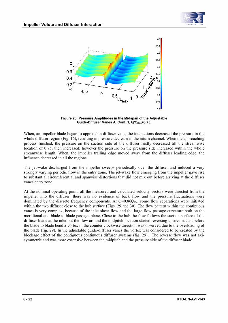
Figure 28: Pressure Amplitudes in the Midspan of the Adjustable Guide-Diffuser Vanes A, Conf_1, Q/QDes=0.75.
When, an impeller blade began to approach a diffuser vane, the interactions decreased the pressure in the whole diffuser region (Fig. 16), resulting in pressure decrease in the return channel. When the approaching process finished, the pressure on the suction side of the diffuser firstly decreased till the streamwise location of 0.75, then increased; however the pressure on the pressure side increased within the whole streamwise length. When, the impeller trailing edge moved away from the diffuser leading edge, the influence decreased in all the regions.
The jet-wake discharged from the impeller sweeps periodically over the diffuser and induced a very strongly varying periodic flow in the entry zone. The jet-wake flow emerging from the impeller gave rise to substantial circumferential and spanwise distortions that did not mix out before arriving at the diffuser vanes entry zone.
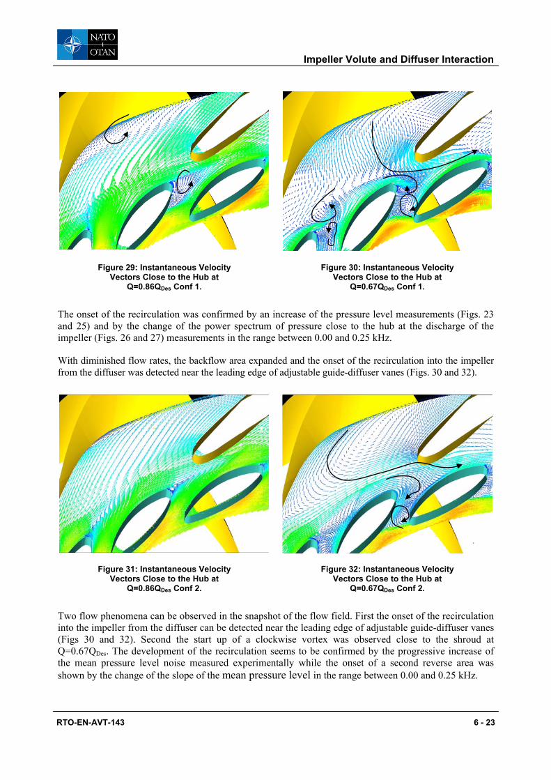
At the nominal operating point, all the measured and calculated velocity vectors were directed from the impeller into the diffuser, there was no evidence of back flow and the pressure fluctuations were dominated by the discrete frequency components. At Q=0.86QDes some flow separations were initiated within the two diffuser close to the hub surface (Figs. 29 and 30). The flow pattern within the continuous vanes is very complex, because of the inlet shear flow and the large flow passage curvature both on the meridional and blade to blade passage plane. Close to the hub the flow follows the suction surface of the diffuser blade at the inlet but the flow around the midpitch location started reversing upstream. Just before the blade to blade bend a vortex in the counter clockwise direction was observed due to the overloading of the blade (fig. 29). In the adjustable guide-diffuser vanes the vortex was considered to be created by the blockage effect of the contiguous continuous diffuser systems (fig. 29). The reverse flow was not axi-symmetric and was more extensive between the midpitch and the pressure side of the diffuser blade.
Impeller Volute and Diffuser Interaction
RTO-EN-AVT-143 6 - 23
Figure 29: Instantaneous Velocity Vectors Close to the Hub at
Q=0.86QDes Conf 1.
Figure 30: Instantaneous Velocity Vectors Close to the Hub at
Q=0.67QDes Conf 1.
The onset of the recirculation was confirmed by an increase of the pressure level measurements (Figs. 23 and 25) and by the change of the power spectrum of pressure close to the hub at the discharge of the impeller (Figs. 26 and 27) measurements in the range between 0.00 and 0.25 kHz.
With diminished flow rates, the backflow area expanded and the onset of the recirculation into the impeller from the diffuser was detected near the leading edge of adjustable guide-diffuser vanes (Figs. 30 and 32).
Figure 31: Instantaneous Velocity Vectors Close to the Hub at
Q=0.86QDes Conf 2.
Figure 32: Instantaneous Velocity Vectors Close to the Hub at
Q=0.67QDes Conf 2.
Two flow phenomena can be observed in the snapshot of the flow field. First the onset of the recirculation into the impeller from the diffuser can be detected near the leading edge of adjustable guide-diffuser vanes (Figs 30 and 32). Second the start up of a clockwise vortex was observed close to the shroud at Q=0.67QDes. The development of the recirculation seems to be confirmed by the progressive increase of the mean pressure level noise measured experimentally while the onset of a second reverse area was shown by the change of the slope of the mean pressure level in the range between 0.00 and 0.25 kHz.
Impeller Volute and Diffuser Interaction
6 - 24 RTO-EN-AVT-143
At flow rate lower than Q=0.53QDes the recirculation zones close to the hub disappear and the back flow area was confined close to the shroud. The change of the recirculation zone from the shroud to the hub, considered to be very important from the stability of the head capacity characteristic at part load (Figs. 21 and 22), was confirmed by the abrupt decrease of the noise due to the disappear of one of the noise source in the range between 0.0 and 3.0 St (Figs. 24 and 25).
Unsteady pressure on the blade surfaces, produced by impeller blade interactions with the instability at the impeller discharge were believed to be the major source of noise. In the noise spectrum, broad humps appeared which were centred to the peaks in source strength spectral distribution initially identified at higher flow rate. All modes in the pressure spectrum generated noise. The peak at St=0.286 generated more acoustic noise than the modes with higher amplitudes (Figs 24 and 25) and was identified as a pressure instability that formed a rotating pattern around the impeller.
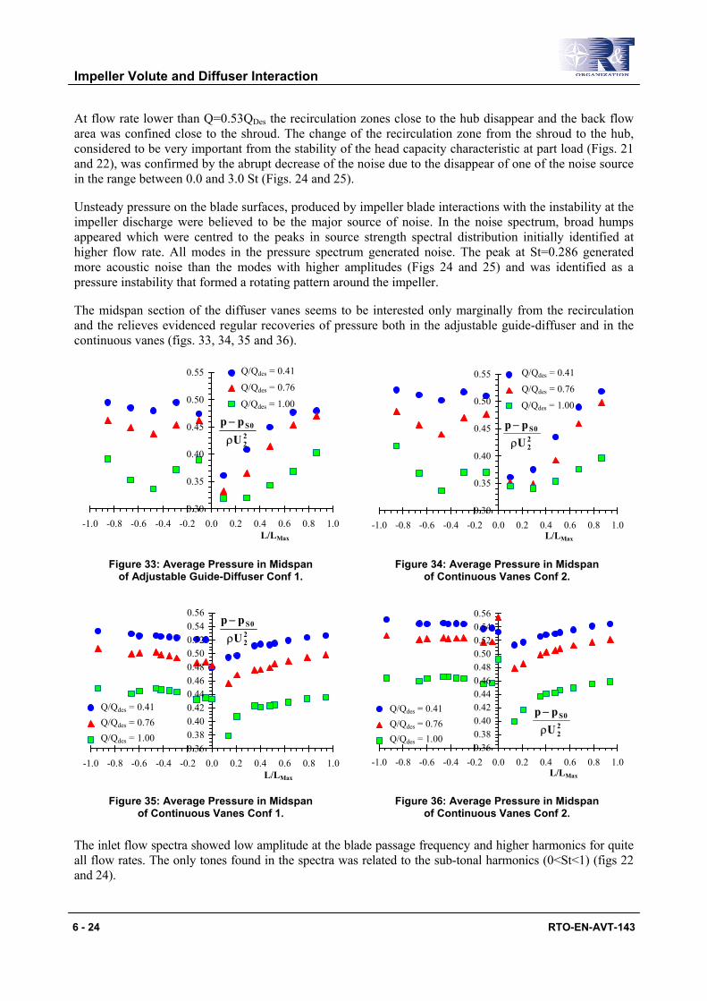
The midspan section of the diffuser vanes seems to be interested only marginally from the recirculation and the relieves evidenced regular recoveries of pressure both in the adjustable guide-diffuser and in the continuous vanes (figs. 33, 34, 35 and 36).
0.30
0.35
0.40
0.45
0.50
0.55
-1.0 -0.8 -0.6 -0.4 -0.2 0.0 0.2 0.4 0.6 0.8 1.0L/LMax
Q/Qdes = 0.76
Q/Qdes = 0.41
Q/Qdes = 1.00
22
0S
Upp
ρ
−
0.30
0.35
0.40
0.45
0.50
0.55
-1.0 -0.8 -0.6 -0.4 -0.2 0.0 0.2 0.4 0.6 0.8 1.0L/LMax
Q/Qdes = 0.76
Q/Qdes = 0.41
Q/Qdes = 1.00
22
0S
Upp
ρ
−
Figure 33: Average Pressure in Midspan of Adjustable Guide-Diffuser Conf 1.
Figure 34: Average Pressure in Midspan of Continuous Vanes Conf 2.
0.360.380.400.420.440.460.480.500.520.540.56
-1.0 -0.8 -0.6 -0.4 -0.2 0.0 0.2 0.4 0.6 0.8 1.0L/LMax
Q/Qdes = 0.76Q/Qdes = 0.41
Q/Qdes = 1.00
22
0S
Upp
ρ
−
0.360.380.400.420.440.460.480.500.520.540.56
-1.0 -0.8 -0.6 -0.4 -0.2 0.0 0.2 0.4 0.6 0.8 1.0L/LMax
Q/Qdes = 0.76Q/Qdes = 0.41
Q/Qdes = 1.0022
0S
Upp
ρ
−
Figure 35: Average Pressure in Midspan of Continuous Vanes Conf 1.
Figure 36: Average Pressure in Midspan of Continuous Vanes Conf 2.
The inlet flow spectra showed low amplitude at the blade passage frequency and higher harmonics for quite all flow rates. The only tones found in the spectra was related to the sub-tonal harmonics (0<St<1) (figs 22 and 24).
Impeller Volute and Diffuser Interaction
RTO-EN-AVT-143 6 - 25
6. REFERENCES [1] Binder, R. C., and Knapp, R. T., 1936, ‘‘Experimental Determination of the Flow Characteristics in
the Volutes of Centrifugal Pumps,’’ Trans. ASME, 58, No. 8, p. 659.
[2] Acosta, A. J., and Bowerman, R. D., 1957, ‘‘An Experimental Study of Centrifugal Pump Impellers,’’ Trans. ASME, 79, pp. 1821–1831.
[3] Stepanoff, A. J., 1957, Centrifugal and Axial Flow Pumps, Wiley, NY.
[4] Agostinelli, A., Nobles, D., and Mockridge, C. R., 1960, ‘‘An Experimental Investigation of Radial Thrust in Centrifugal Pumps,’’ ASME J. Eng. Power, 80, pp. 120–126.
[5] Biheller, H. J., 1965, ‘‘Radial Forces on the Impeller of Centrifugal Pumps with Volute, Semivolute, and Fully Concentric Casings,’’ ASME J. Eng. Power, 85, pp. 319–323.
[6] Hergt, P., and Krieger, P. 1972, ‘‘Radial Forces and Moments Acting on the Impeller of Volute Casing Pumps,’’ Proceedings of the Fourth Conference of Fluid Machinery, Budapest, pp. 599–619.
[7] Kanki, H., Kawata, Y., and Kawatani, T., 1981, ‘‘Experimental Research on the Hydraulic Excitation Force on the Pump Shaft,’’ Proceedings, ASME Design Engineering Technical Conf., 81-DET-71, Sept., Hartford, CT.
[8] Chamieh, D. S., Acosta, A. J., Brennen, C. E., Caughey, T. K., and Franz, R., 1985, ‘‘Experimental Measurements of Hydrodynamic Radial Forces and Stiffness Matrices for a Centrifugal Pump Impeller,’’ ASME J. Fluids Eng., 107, pp. 307–315.
[9] De Ojeda, W., Flack, R. D., and Miner, S. M., 1995, ‘‘Laser Velocimetry Measurements in a Double Volute Centrifugal Pump,’’ Int. J. Rotat. Mach., 1, Nos. 3–4, pp. 199–214.
[10] Inoue, M., and Cumpsty, N. A., 1984, ‘‘Experimental Study of Centrifugal Impeller Discharge Flow in Vaneless and Vaned Diffusers,’’ASME J. Eng. Gas Turbines Power, 106, pp. 455–467.
[11] Sideris, M. T., and Van den Braembussche, R. A., 1987, ‘‘Influence of a circumferential exit pressure distortion on the flow in an impeller and diffuser,’’ ASME J. Turbomach., 109, pp. 48–54.
[12] Arndt, N., Acosta, A. J., Brennen, C. E., and Caughey, T. K., 1989, ‘‘Rotor- Stator Interaction in a Diffuser Pump,’’ ASME J. Turbomach., 111, pp. 213–221.
[13] Arndt, N., Acosta, A. J., Brennen, C. E., and Caughey, T. K., 1990, ‘‘Experimental Investigation of Rotor-Stator Interaction in a Centrifugal Pump With Several Vaned Diffusers,’’ ASME J. Turbomach., 112, pp. 98–108.
[14] Kaupert, K. A., and Staubli, T., 1999, ‘‘The Unsteady Pressure Field in a High Specific Speed Centrifugal Pump Impeller. Part I: Influence of the Volute,’’ ASME J. Fluids Eng., 121, pp. 621–626.
[15] Chu, S., Dong, R., and Katz, J., 1995, ‘‘Relationship Between Unsteady Flow, Pressure Fluctuations, and Noise in a Centrifugal Pump; Part A: Use of PDV Data to Compute the Pressure Field,’’ ASME J. Fluids Eng., 117, pp. 24–29.
[16] Chu, S., Dong, R., and Katz, J., 1995, ‘‘Relationship Between Unsteady Flow, Pressure Fluctuations, and Noise in a Centrifugal Pump; Part B: Effects of Blade-Tongue Interaction,’’ ASME J. Fluids Eng., 117, pp. 30–35.
Impeller Volute and Diffuser Interaction
6 - 26 RTO-EN-AVT-143
[17] Dong, R., Chu, S., and Katz, J., 1997, ‘‘Effect of Modification to Tongue and Impeller Geometry on Unsteady Flow, Pressure Fluctuations, and Noise in a Centrifugal Pump,’’ ASME J. Turbomach., 119, pp. 506–515.
[18] Paone, N., Riethmuller, M. L., and Van den Braembussche, R. A., 1989, ‘‘Experimental Investigation of the Flow in the Vaneless Diffuser of a Centrifugal Pump by Particle Image Displacement Velocimetry’’ Exp. Fluids, 7, pp. 371–378.
[19] Domm, U., and Hergt, P., 1970, ‘‘Radial Forces on Impeller of Volute Casing Pumps,’’ Flow Research on Blading, Elsevier, NY, pp. 305–321.
[20] Lorett, J. A., and Gopalakrishnan, S., 1986, ‘‘Interaction Between Impeller and Volute of Pumps at Off-Design Conditions,’’ ASME J. Fluids Eng., 108, pp.12–18.
[21] Fongang, R., Colding-Jorgenson, J., and Nordman, R., 1998, ‘‘Investigation of Hydrodynamic Forces on Rotating and Whirling Centrifugal Pump Impellers,’’ ASME J. Turbomach., 120, pp. 179–185.
[22] Hillewaert, K., and Van den Braembussche, R. A., 1999, ‘‘Numerical Simulation of Impeller-Volute Interaction in Centrifugal Compressor,’’ ASME J. Turbomach., 121, pp. 603–608.
[23] Longatte, F., and Kueny, J. L., 1999, ‘‘Analysis of Rotor-Stator-Circuit Interactions in a Centrifugal Pump,’’ ASME Paper FEDSM99-6866.
[24] Zhang, M., Wang, H., and Tsukamoto, H., 2002, ‘‘Numerical Analysis of Unsteady Hydrodynamic forces on a Diffuser Pump Impeller due to Rotor-Stator Interaction,’’ ASME Paper FEDSM2002-31181.
[25] Gonza´lez, J., Ferna´ndez, J., Blanco, E., and Santolaria, C., 2002, ‘‘Numerical Simulation of the Dynamic Effects Due to Impeller-Volute Interaction in a Centrifugal Pump,’’ ASME J. Fluids Eng., 124, pp. 348–355.
[26] Gonza´lez, J., Santolaria, C., Blanco, E., and Ferna´ndez, J., 2002, ‘‘Unsteady Flow Structure on a Centrifugal Pump: Experimental and Numerical Approaches,’’ ASME Paper FEDSM2002-31182.
[27] Arndt, N., Acosta, A J., Brennen, C. E., and Caughey, T. K., 1989, ‘‘Rotor/ Stator Interaction in a Diffuser Pump,’’ ASME J. Turbomach., 111, pp. 213–221.
[28] Arndt, N., Acosta, A J., Brennen, C. E., and Caughey, T. K., 1990, ‘‘Experimental Investigation of Rotor/Stator Interaction in a Centrifugal Pump with Several Vaned Diffusers,’’ ASME J. Turbomach., 111, pp. 213–221.
[29] Tsukamoto, H., Uno, M., Hamafuku, H., and Okamura. T., 1995, ‘‘Pressure Fluctuation Downstream of a Diffuser Pump Impeller,’’ The 2nd Joint ASME/JSME Fluids Engineering Conference, Forum of Unsteady Flow, FED-Vol. 216, pp. 133–138.
[30] Dring, R. P., Joslyn, H. D., Hardwin, L. W., and Wagner, J. H., 1982 ‘‘Turbine Rotor-Stator Interaction,’’ ASME J. Eng. Power, 104, pp. 729–742.
[31] Dong, R., Chu, S., and Katz, J., 1992, ‘‘Quantitative-Visualization of the Flow Within the volute of a Centrifugal Pump. Part B: Results,’’ ASME J. Fluids Eng., 114, No. 3, pp. 396–403.
[32] Akin, O., and Rockwell, D., 1994, ‘‘Flow Structure in a Radial Flow Pumping System Using High-Image-Density Particle Image Velocimetry,’’ ASME J. Fluids Eng., 116, pp. 538–544.
Impeller Volute and Diffuser Interaction
RTO-EN-AVT-143 6 - 27
[33] Wuibaut G., Bois, G., Dupont, P., Caignaert, G., and Measurements in the Impeller and the Vaneless Diffuser of a Radial Flow Pump in Design and Off-Design Operating Conditions,” ASME J. Fluids Eng., 124, pp. 791–797.
[34] Qin, W., and Tsukamoto, H., 1997, ‘‘Theoretical Study of Pressure Fluctuations Downstream of a Diffuser Pump Impeller-Part 1: Fundamental Analysis on Rotor-Stator Interaction,’’ ASME J. Fluids Eng., 119, pp. 647–652.
[35] Shi, F., and Tsukamoto, H., 2001, ‘‘Numerical Study of Pressure Fluctuations Caused by Impeller-Diffuser Interaction in a Diffuser Pump Stage,’’ ASME J. Fluids Eng., 123, pp. 466–474.
[36] Wang, H., and Tsukamoto, H., 2001, ‘‘Fundamental Analysis on Rotor-Stator Interaction in a Diffuser Pump by Vortex Method,’’ASME J. Fluids Eng., 123, pp. 737–747.
[37] Yoshida, Y., Murakami, Y., Tsurusaki, T., and Tsujimoto, Y., 1991, ‘‘Rotating Stalls in Centrifugal Impeller/Vaned Diffuser Systems,’’ Proceedings of the First ASME/JSME Joint Fluids Engineering Conference, ASME, New York, FED-107, pp. 125–130.
[38] Pump by Vortex Method,’’ASME J. Fluids Eng., 123, pp. 737–747.
Impeller Volute and Diffuser Interaction
6 - 28 RTO-EN-AVT-143


![Impeller Volute and Diffuser Interaction · 2011-05-14 · Impeller Volute and Diffuser Interaction 6 - 2 RTO-EN-AVT-143 Paone et al. [18] at VKI used particle image velocimetry to](https://static.fdocuments.in/doc/165x107/5e8c6dcccab12058af64c81f/impeller-volute-and-diffuser-interaction-2011-05-14-impeller-volute-and-diffuser.jpg)


