IMIA Paper 85(14) Biomass Power Plants · IMIA Paper 85(14) Biomass Power Plants 1.0 Introduction ....
34
IMIA WORKING GROUP PAPER 85(14) BIOMASS POWER PLANTS 46 TH ANNUAL IMIA CONFERENCE - FRANCE Working Group Stephanie Watkins, HSB – Chairperson Mamoon Alyah, LWG Chris Bluckert, BRIM Stuart Brazier, Inter Hannover Alan Cain, RSA Thomas Gebert, Zurich Andy Kane, HSB HO Kun Hong, SCOR Esdras Martinez, Swiss Re Pat Jennings, HSB Tom Wilson, Inter Hannover Mike Robertson, Liberty Mutual – IMIA Executive Committee Sponsor
-
Upload
trinhquynh -
Category
Documents
-
view
215 -
download
2
Transcript of IMIA Paper 85(14) Biomass Power Plants · IMIA Paper 85(14) Biomass Power Plants 1.0 Introduction ....

IMIA WORKING GROUP PAPER 85(14)
BIOMASS POWER PLANTS
46TH ANNUAL IMIA CONFERENCE - FRANCE
Working Group Stephanie Watkins, HSB – Chairperson Mamoon Alyah, LWG Chris Bluckert, BRIM Stuart Brazier, Inter Hannover Alan Cain, RSA Thomas Gebert, Zurich Andy Kane, HSB HO Kun Hong, SCOR Esdras Martinez, Swiss Re Pat Jennings, HSB Tom Wilson, Inter Hannover Mike Robertson, Liberty Mutual – IMIA Executive Committee Sponsor

Executive Summary .......................................................................................................... 4�1.0 Introduction ................................................................................................................. 5�2.0 Biomass Fuel and Technology .................................................................................... 6�
2.1 Fuel ......................................................................................................................... 6�2.2 Fuel Handling and Storage ..................................................................................... 8�
2.2.1 Receiving.......................................................................................................... 8�2.2.2 Storage ............................................................................................................. 9�2.2.3 Reclaim ............................................................................................................ 9�2.2.4 Boiler Feed ..................................................................................................... 10�
2.3 Combustion Systems ............................................................................................ 10�2.3.1 Direct-Fired Biomass ...................................................................................... 11�
2.3.1.1 Stoker Fired Systems .............................................................................. 11�2.3.1.2 Fluidized Bed Combustion ...................................................................... 12�2.3.1.3 Gasification .............................................................................................. 12�
2.3.2 Co–Firing Biomass ......................................................................................... 12�2.4 Boiler Design Considerations ................................................................................ 13�
2.4.1 Erosion ........................................................................................................... 13�2.4.2 Corrosion ........................................................................................................ 13�2.4.3 Slagging/Fouling ............................................................................................. 14�
2.5 Boiler Performance ............................................................................................... 14�2.6 Conversion of Conventional Plants to Biomass .................................................... 14�2.7 Air Quality Control System (AQCS) Equipment .................................................... 15�
2.7.1 Carbon Monoxide (CO) Emissions ................................................................. 15�2.7.2 NOx Emissions ............................................................................................... 15�2.7.3 Particulate (Flyash) Emissions ....................................................................... 16�
2.7.3.1 Electrostatic Precipitators (ESPs) ........................................................... 16�2.7.3.2 Fabric Filters (Baghouses) ...................................................................... 17�
3.0 Insurance Risks ......................................................................................................... 18�3.1 Construction Risks ................................................................................................ 18�
3.1.1 Prototypical Design ........................................................................................ 18�3.1.2 Retrofitted Plants ............................................................................................ 19�3.1.3 Testing and Commissioning ........................................................................... 19�
3.2 Operating Risks ..................................................................................................... 20�3.2.1 Operators ....................................................................................................... 20�3.2.2 Fuel Quality and Availability ........................................................................... 20�
3.2.3 Explosion and Fire ................................................................................................. 21�
2
3
3.2.4 Maintenance and Housekeeping .................................................................... 22�3.2.5 Natural Catastrophes ..................................................................................... 23�
3.3 Financial Risks ...................................................................................................... 24�3.3.1 Delay in Start-up (DSU) / Advance Loss of Profit (ALOP) .............................. 24�3.3.2 Business Interruption ...................................................................................... 25�
3.3.2.1 Income Streams ...................................................................................... 25�3.3.2.1.1 Government Incentives ...................................................................... 25�3.3.2.1.2 Supplying a Manufacturing Process .................................................. 26�3.3.2.1.3 Waste ................................................................................................. 26�
3.3.2.2 Fuel Supply ............................................................................................. 26�3.3.2.2.1 Fuel Take or Pay ............................................................................... 26�3.3.2.2.2. Supply Chain .................................................................................... 26�3.3.2.2.3 Extended Business Interruption ......................................................... 27�
4.0 Conclusion ................................................................................................................ 27�5.0 Appendices ............................................................................................................... 28�
Appendix 1 – Biomass Fires and Explosions: 2008-2012 ............................... 28�Appendix 2 – Sample Maintenance Checklist for Site Surveys ........................ 32�Appendix 3 – Sample Underwriting Risk Assessment Guide ........................... 33�
6.0 Other References ...................................................................................................... 34�
IMIA Paper 85(14) Biomass Power Plants
Executive Summary Power generation from biomass is achieved by using a wide variety of fuel types and processes. Technologies range from the commercially proven, such as solid fuel combustion, to those only starting to be deployed commercially, like gasification and pyrolysis. Direct combustion of biomass for power generation is a proven, commercially available technology that is used in scales ranging from a few MW to over 100 MW. Over 80% of installed biomass is based on combustion of solid feedstock, using steam turbines for power generation. Approximately half of this capacity also produces heat (combined heat and power) for industry, residential or service sectors.1 This paper focuses on medium to large-scale biomass power generation plants that use solid biomass fuels either alone, or co-fired with conventional fuels. This paper will not deal in detail with:
• Small biomass plants • Municipal solid waste or non-solid feedstock • Other conversion processes such as gasification, pyrolysis or anaerobic digestion
Some of these topics could be appropriate for future IMIA Working Group papers. The aim of this paper is to provide an overview of the biomass to energy process and the risks and exposures inherent therein, including feedstock delivery, storage, handling, and the combustion process. This paper will not focus on the risks associated with the steam turbine, generator and electrical transmission equipment. This is usually standard utility equipment and has been discussed in previous IMIA papers.
1 The International Renewable Energy Agency (IRENA). Biomass for Power Generation – Renewable Energy Technologies: Cost Analysis Series. June 2012.
4
IMIA Paper 85(14) Biomass Power Plants
1.0 Introduction Biomass is a generic term for plant and animal matter. In the renewable energy context it typically refers to:
• Agricultural residues and by-products such as straw, sugarcane fiber, rice hulls and animal waste
• Residue from forestry, construction, and wood processing industries • Energy crops grown specifically to be used as fuel
Biomass power is generated from biomass that is converted into electricity, typically though combustion or gasification. Unlike wind farms, photovoltaic plants or hydro power, biomass power is less dependent on weather and environmental conditions. As a result, it is an extremely reliable renewable energy source and can produce a steady and dependable flow of electricity 24 hours a day, 7 days a week. This reliability allows utilities to easily add biomass power to their base load supply to meet energy demands. Further, biomass power is less location specific than other ‘green’ power sources and can be developed almost anywhere sufficient feedstock is accessible. In 2012 global installed capacity of biomass was estimated to be 76GW, with electricity generation representing between 264-529TWh.2
Biomass Type 2012 Capacity (GW)
%Growth Rate 2011 to 2012
Estimated electricity generation in 2012 (TWh)
Solid biomass 50 3.5 175-350 Biogas 14 10 47-95 Municipal Solid Waste 10 5 36-72 Liquid biofuels 2 20 6-12 Total 76 5 264-529
Figure 1: Summary of global biomass electricity market
The global leader in biomass power production is the United States, with an installed capacity of approximately 17GW and electricity generation of 61TWh in 2012. This is an increase of 1% compared to 2011. The European Union (28.3GW), China (4.4GW), India (3.8GW) and Japan (3.3GW) are also large producers of bioelectricity. Significant growth is anticipated in biomass power generation over the next decade, largely driven by government led renewable energy incentives. Total capacity for planned biomass power generation projects either under construction or with secured financing was 10GW in 2013. The vast majority of these projects (94%) will use combustion technology to convert solid biomass fuel.3 In Europe, Germany and the United Kingdom are anticipated to be the biggest markets for biomass technologies, especially those using co-firing techniques. Growth in China is expected to come from more extensive usage of the large quantities of agricultural residues it produces. In South America further growth is likely from the continuing use of bagasse for electricity generation. 2 Renewable Energy Policy Network for the 21st Century (REN21). Renewables 2012– Global Status Report. 2012. 3 The International Renewable Energy Agency (IRENA). Biomass for Power Generation – Renewable Energy
Technologies: Cost Analysis Series. June 2012.
5

IMIA Paper 85(14) Biomass Power Plants
2.0 Biomass Fuel and Technology 2.1 Fuel Organic materials used for biomass fuel include:
• Forestry residues such as wood debris and waste streams from forestry management and logging
• Mill and wood processing by-products, such as sawdust and wood chips • Agriculture residues including crop waste, sugar cane bagasse, vineyard and
orchard cuttings • Urban wood from construction industry scrap and waste collected through
recycling initiatives • Purpose grown, biomass crops such as rape, oilseed, corn, fast growing trees
(willow, poplar), straw and miscanthus
Figure 2: From top left clockwise: bagasse pile, baled corn stover, switch grass harvesting, woodchips4 Distinguishing features of biomass fuels compared to conventional fossil fuels include:
• relatively low energy density, requiring larger volumes of fuel to be stored, transported and consumed in order to achieve equivalent energy outputs
• variability in volume and constituents related to growing seasons and harvesting activities
• higher moisture content, combined with combustion derived alkali components such as chlorine, sulphur and trace metals
4 Photos by Warren Gretz, National Renewable Energy Laboratory (NREL) 06453, 04742, 00591, 04393.
6

IMIA Paper 85(14) Biomass Power Plants
To illustrate the significant differences in energy density between biomass and conventional fuels, figure 3 below sets out typical calorific values of some common conventional and biomass fuels.
Fuel Net Calorific Value (CV) by mass GJ/tonne
New Calorific Value (CV) by mass kWh/kg
Bulk density kg/m3
Energy density by volume
MJ/m3
Energy density by volume
kWh/m3 Wood chips
(30% MC) 12.5 3.5 250 3,100 870
Log wood (stacked air dry:
20% MC)
14.7 4.1 350-500 5,200-7,400 1,400-2,000
Wood (solid-oven dry)
19 5.3 400-600 7,600-11,400 2,100-3,200
Wood pellets 17 4.8 650 11,000 3,100 Miscanthus
(bale – 25% MC) 13 3.6 140-180 1,800-2,300 500-650
House coal 27-31 7.5-8.6 850 23,000-26,000 6,400-7,300 Anthracite 33 9.2 1,100 36,300 10,100 Heating Oil 42.5 11.8 845 36,000 10,000 Natural gas
(NTP) 38.1 10.6 0.9 35.2 9.8
LPG 46.3 12.9 510 23,600 6,600
Figure 3: Net Caloric Value by fuel type To enhance combustion efficiency and reduce transportation cost a variety of techniques are used to improve the energy density of biomass fuels. The most common are drying (natural or accelerated) pelletising, torrefaction, and briquetting. Of these, pelletising is the most commercially available and widespread. Biomass power plants are often designed to use a particular agricultural or forestry residue, or a specific energy crop, but can be more economically successful when able to use variable fuel sources. This allows plant operators to react to changes in supply and subsidy frameworks. Design attention should focus on the nature of the fuel, variable fuel conditions and the potential use of fuel types outside original design specification.
It is important that designers of combustion processes and boilers have a thorough understanding of the properties of the biomass fuel being used. For example, unprocessed fuel with high moisture content will require a different combustion system than a highly processed fuel with low moisture content. Combustion rates, peak flame temperatures and gas flow through the boiler vary widely by fuel type. This requires matching the combustion properties with the heat absorption of the boiler. The amount of slagging, fouling and corrosion is driven by a combination of fuel ash constituents, combustion technology process and boiler design. By way of example, different wood types typically used for fuel, such as slow growing white wood and fast growing coppice, including cuttings (twigs, branches), can have ash fusion temperatures that vary by over 200 deg C.5 This requires that boiler tube spacing and temperatures are matched in order to minimize slagging and fouling.
5 Technical Research Centre of Finland; Wilen, C., Moilanen, A. & Kurkela, E. Biomass Feedstock Analysis. 1996.
7

IMIA Paper 85(14) Biomass Power Plants
2.2 Fuel Handling and Storage Biomass has to be transported, stored and sometimes prepared on site. This adds complexity to biomass plants from both the construction and operational perspective. The properties of biomass feedstock, including density, particle size and moisture content dictate the systems used for handling and storing. Handling systems should be designed for the specified fuel but also allow for flexibility for similar feedstock. However, systems designed to handle highly processed fuels cannot typically be used for raw feedstock and vice versa. The fuel receiving and handling process follows a progression of steps; receiving, storage, reclaim and boiler feed. 2.2.1 Receiving
The fuel delivery method and fuel quantity delivered determines the receiving system design. For truck delivery, hydraulic dumps are commonly used to move fuel into a receiving hopper. These systems can handle both processed fuels and sized raw feedstock. After the trucks are weighed, they enter the dumper, which is raised using a large hydraulic ram that lifts the entire platform. The fuel can be dumped into a receiving hopper with a feed system, such as an augur, that transfers the fuel into the storage area. Fuel can also be dumped into pits and loaders are then used to move it into storage. For large pellet fired systems, rail dumps are common. The fuel receiving bins are typically located below the track and rail cars dump into bins, either directly or through a rotary dumper. Fuel is then transferred from the receiving bin by belt conveyors to the storage bins. For small particle sizes, pneumatic conveying systems offer greater flexibility in routing than traditional belt conveyors. Equipment specific to pneumatic systems include positive displacement blowers and rotary feeders that function as air locks.
Figure 4: Truck dump and rail unloading6
6 Photos by Warren Gretz, National Renewable Energy Laboratory (NREL) 06372, 05663.
8
IMIA Paper 85(14) Biomass Power Plants
2.2.2 Storage
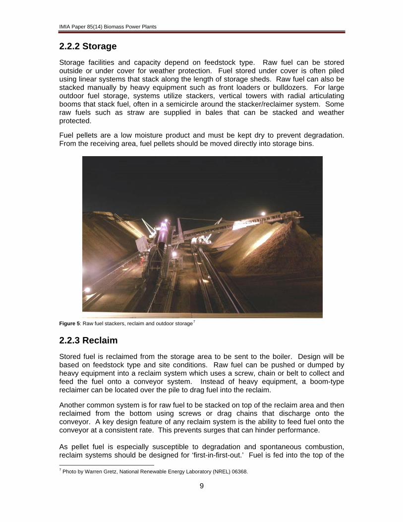
Storage facilities and capacity depend on feedstock type. Raw fuel can be stored outside or under cover for weather protection. Fuel stored under cover is often piled using linear systems that stack along the length of storage sheds. Raw fuel can also be stacked manually by heavy equipment such as front loaders or bulldozers. For large outdoor fuel storage, systems utilize stackers, vertical towers with radial articulating booms that stack fuel, often in a semicircle around the stacker/reclaimer system. Some raw fuels such as straw are supplied in bales that can be stacked and weather protected. Fuel pellets are a low moisture product and must be kept dry to prevent degradation. From the receiving area, fuel pellets should be moved directly into storage bins.
Figure 5: Raw fuel stackers, reclaim and outdoor storage7 2.2.3 Reclaim
Stored fuel is reclaimed from the storage area to be sent to the boiler. Design will be based on feedstock type and site conditions. Raw fuel can be pushed or dumped by heavy equipment into a reclaim system which uses a screw, chain or belt to collect and feed the fuel onto a conveyor system. Instead of heavy equipment, a boom-type reclaimer can be located over the pile to drag fuel into the reclaim. Another common system is for raw fuel to be stacked on top of the reclaim area and then reclaimed from the bottom using screws or drag chains that discharge onto the conveyor. A key design feature of any reclaim system is the ability to feed fuel onto the conveyor at a consistent rate. This prevents surges that can hinder performance. As pellet fuel is especially susceptible to degradation and spontaneous combustion, reclaim systems should be designed for ‘first-in-first-out.’ Fuel is fed into the top of the 7 Photo by Warren Gretz, National Renewable Energy Laboratory (NREL) 06368.
9

IMIA Paper 85(14) Biomass Power Plants
bin and reclaimed from the bottom. In some designs, fuel is reclaimed using underpile rotary screws that sweep the bottom of the bins to ensure fuel does not stagnate. Other systems use sloped bottom bins with screw conveyors. 2.2.4 Boiler Feed Fuel is conveyed to the boiler area where it is usually stored in surge or day bins. The ability to smoothly and accurately modulate fuel feed is critical to effective boiler performance. Surge bins provide short term storage (30 minutes to several hours) and allow a constant source of fuel to metered feeders. For raw fuel, such as wood chips, surge bins may be a standard sloped bin with a traveling screw reclaim that transfers the fuel to drag chain conveyors incorporating ‘robbing’ screws to meter the fuel to the feeders. Other systems are designed to feed fuel into the top of a live bottom surge bin. The top of the bin is smaller than the bottom (negative sloped) to prevent pluggage or bridging. Fuel is then fed out of the bottom using screw augers that meter it to the feeder. For maintenance, it is important that fuel feed systems can be isolated from the boiler. This is usually achieved with slide gates. Some fuel, such as straw requires additional processing before it is fed to the boiler. Raw fuel can be processed into finer particles for suspension burning, down to as small as 4 mm (3/8”). Fuel may be processed using shredders, hammer mills or grinders to obtain the optimal size prior to entering the boiler. These systems use a pneumatic transport to feed the fuel to the boiler. Pellet fuel is typically fed from the bottom of surge bins through an airlock rotary feeder into a mill for processing. Pellets are broken down into their constituent particle size and transported to the boiler using pneumatic transport. It is critical that all tramp iron is removed to prevent sparks during the milling process. This will occur in one or more locations upstream of the pellet mill. 2.3 Combustion Systems Firing technology design should be based on feedstock availability, its preparation and local environmental concerns. A key factor is the extent to which fuel is already processed. Larger, unprocessed fuel with high moisture content will require a different combustion system than a highly processed fuel such as pellets. Raw and processed fuel types are not interchangeable with a chosen firing system. However, fuel flexibility within a particular type is a key influence on technology design. Plants designed for fuel flexibility will be able to adapt to changes in fuel supply over time.8 Commercially available systems for raw fuels include stokers, bubbling fluidized beds and circulating fluidized beds. Finely ground or shredded raw fuel can be combusted in suspension as a supplement to coal firing. Newer technology includes gasification of raw fuel to generate combustible gases. While most gasification technology is still considered prototypical, some is commercially available.9
8 National Renewable Energy Laboratory; Wiltsee, G. Lessons Learned from Existing Biomass Power Plants. 2000. 9 Energy and Environmental Analysis, Inc. Biomass Combined Heat and Power Catalog of Technologies. 2007.
10

IMIA Paper 85(14) Biomass Power Plants
Figure 6: Diagram of a biomass combined heat and power plant10 2.3.1 Direct-Fired Biomass 2.3.1.1 Stoker Fired Systems Stoker firing is a mature technology with many installed units firing 100% biomass or biomass in conjunction with other fuel such as coal. This technology is best suited for higher moisture raw fuel with up to 60% moisture content. Combustion air is supplied under a grate (fixed or moving) and fuel is primarily combusted on the grate. Air is injected above the grate to complete the combustion and to minimize carbon monoxide. The hot gases then travel from the furnace to the heat absorbing sections of the boiler. Fuel is typically stored and handled in chipped form. For a typical stoker, fuel sizing is 2” x 2” x ¼”. Fuel is usually thrown or spread, pneumatically or mechanically, to the back of a grate which moves slowly to the front, with combustion taking place on the grate. Finer particles are burned in suspension, while larger particles combust on the grate. Other designs incorporate stationary grates that are angled and vibrate to move along fuel and ash. Vibrating grates can be water or air cooled. Ash is dropped off into hoppers under the stoker.
10 http://www.biomassinnovation.ca/CombinedHeatAndPower.html
11

IMIA Paper 85(14) Biomass Power Plants
Of stoker designs, the spreader stoker has the best response time for boiler operation. Stoker technology is proven and well suited for many non-processed fuels, but has a slower response time and relatively higher emissions compared to fluidized bed combustion. 2.3.1.2 Fluidized Bed Combustion
Air is injected into the bottom of the boiler through a series of fluidizing nozzles into a bed of inert material such as sand. This air fluidizes the bed material and the combustion process begins. In a bubbling fluidized bed (BFB) combustion system fuel is introduced and combusted within the bed. Heat transfer surfaces are located in this zone. To maintain bed level, heavier ash particles are drained from the bottom and lighter particles exit into the furnace where combustion is completed with the addition of air above the bed. Heat is released and hot gases and ash travel upward through the furnace to the heat absorbing sections. In a circulating fluid bed (CFB) combustion system, upward velocity of air carries the fuel, bed material and ash up into the furnace where combustion occurs. A separator, usually a cyclone, will capture the larger fuel particles (along with ash and bed material), returning them to the bottom of the bed to complete the combustion process. Combustion gases exit the cyclone and continue to the heat recovery section. Fluidized bed systems can operate under a wide range of load conditions and offer significant flexibility over stokers. They operate at a lower temperature, which minimizes nitrogen oxides (NOx). Limestone can be used if sulfur dioxide (SO2) is of concern.11 2.3.1.3 Gasification These units utilize a bubbling bed and fire the biomass in a process very similar to BFB. The key difference is the amount of air introduced into the bed is significantly lower. Instead of combusting in the bed, the fuel is pyrolized under oxygen lean conditions. This produces a gas product, rich in carbon monoxide that is burned downstream in the furnace or in a separate combustor. Unlike other gasification technologies being developed (and not discussed here), BFB gasification does not require removal of tar material and ash as part of the pyrolysis process. Gasification technology is available commercially, but is not as widespread as other combustion technologies. 2.3.2 Co–Firing Biomass Biomass can be co-fired in existing coal fired units. Utility generators are increasingly interested in utilizing biomass in coal fired plants to replace coal with CO2 neutral biomass. Firing biomass in existing plants to reduce coal consumption requires lower capital costs compared to new installations, as existing infrastructure (such as the boiler, turbine and electrical equipment) can often be reused.12 In the utility industry a multitude of sites have experience co-firing biomass with fossil fuels. For co-firing applications, biomass is often fired in suspension after a certain level of firing rate is reached on the 11 Energy and Environmental Analysis, Inc. Biomass Combined Heat and Power Catalog of Technologies. 2007. 12 Baxter, L., & Koppejan, J. Biomass-coal Co-combustion: Opportunity for Affordable Renewable Energy. January 2004.
Retrieved February 27, 2014, from IEA Bioenergy: http://www.ieabcc.nl/
12
IMIA Paper 85(14) Biomass Power Plants
base coal fire. The most commonly co-fired fuel is pellets, but shredded straw and other feedstock can also be used. Pellets are commonly fed into a high speed milling system where they are finely ground. The resulting particles are then pneumatically transported to the boiler where they are injected and burned in suspension. The fuel can either be injected into the existing coal lines and fired with the coal or fired separately.
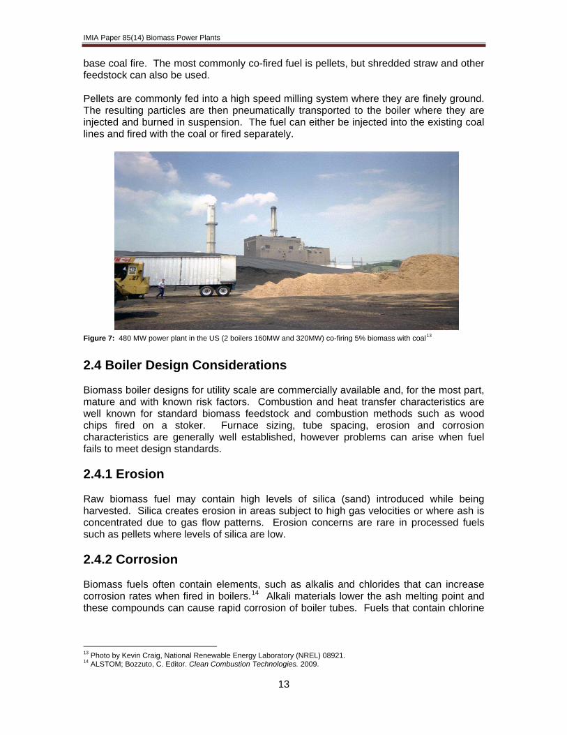
Figure 7: 480 MW power plant in the US (2 boilers 160MW and 320MW) co-firing 5% biomass with coal13
2.4 Boiler Design Considerations Biomass boiler designs for utility scale are commercially available and, for the most part, mature and with known risk factors. Combustion and heat transfer characteristics are well known for standard biomass feedstock and combustion methods such as wood chips fired on a stoker. Furnace sizing, tube spacing, erosion and corrosion characteristics are generally well established, however problems can arise when fuel fails to meet design standards.
2.4.1 Erosion
Raw biomass fuel may contain high levels of silica (sand) introduced while being harvested. Silica creates erosion in areas subject to high gas velocities or where ash is concentrated due to gas flow patterns. Erosion concerns are rare in processed fuels such as pellets where levels of silica are low. 2.4.2 Corrosion Biomass fuels often contain elements, such as alkalis and chlorides that can increase corrosion rates when fired in boilers.14 Alkali materials lower the ash melting point and these compounds can cause rapid corrosion of boiler tubes. Fuels that contain chlorine
13 Photo by Kevin Craig, National Renewable Energy Laboratory (NREL) 08921. 14 ALSTOM; Bozzuto, C. Editor. Clean Combustion Technologies. 2009.
13

IMIA Paper 85(14) Biomass Power Plants
can create significant corrosion on boiler parts.15 The highest rates of corrosion occur on high temperature metals when inorganic materials are in a liquid phase. When agricultural crops are fired alone or in high concentrations, it is recommended that chlorine content be determined and monitored. If fuels with high chlorides are fired, high nickel weld overlay tubing should be considered in areas affected by wastage. Low temperature corrosion can occur in areas where exit gases reach dew point temperature. 2.4.3 Slagging/Fouling Alkali materials in ash have lower melting points than ash from coal firing. This can result in ash that is sticky and agglomerates. These accumulations can form in the furnace where they can create large clinkers or in tube sections, interfering with heat absorption and efficiency of combustion. Usually, there is little equipment damage that would result in a property or equipment breakdown claim, but it is an indication of potential concerns with corrosion in the future. 2.5 Boiler Performance Compared to traditional rankine cycle coal fired plants, those firing 100% biomass typically operate at lower pressures and temperatures, often superheat steam only with no reheat. As such, average heat rates are higher and therefore overall cycle efficiency lower than traditional coal fired utility plants. Plants in the United States typically use the Higher Heating Value (HHV) of the fuel for determining heat rate, compared to the lower heating value (LHV) common in Europe. As of 2010, the highest reported efficiency of a biomass plant was 35%.16 In co-firing applications, the rule of thumb is 20% co-firing or less will not impact boiler performance significantly. Generally, there is a slight decrease in boiler efficiency with the addition of biomass due to higher hydrogen and moisture content. Existing equipment, such as fans, are not usually affected. However, co-firing requires use of soot blowing equipment if ash constituents increase the fouling potential. Higher than 20% co-firing means boiler modification or derating may be required. 2.6 Conversion of Conventional Plants to Biomass Conversion of coal fired boilers to biomass is often seen with older, smaller, coal fired boilers that are being considered for decommissioning. In areas with a pulp and paper history, old recovery boilers have been converted to steam generation for power. The most common scenario is for a large part of the structure and boiler to be retained. New fuel firing equipment, either a BFB or stoker, is added. Heat exchange surfaces, including superheaters, reheaters and economizer surfaces are often changed, depending on the characteristics of the biomass. For example, furnace temperatures, gas mass flows and temperature will differ from the original design. All of these changes must be considered to ensure boiler output in pressure and temperature matches the requirements of the steam turbine.
15 Duong, D. Chlorine Issues with Biomass Cofiring in Pulverized Coal Boilers: Sources, Reactions and Consequences - A Literature Review. 2009. 16 McHale & Associates, Inc. Biomass Technology Review. 2010.
14
IMIA Paper 85(14) Biomass Power Plants
In July 2012 the 6 unit Drax power plant announced it would convert the largest coal fired plant in the United Kingdom to fire predominantly biomass. The first of 3 units was converted in April 2013.17 There is limited information on 100% conversions of power plants to biomass using pellets as the fuel source - an emerging technology to watch. 2.7 Air Quality Control System (AQCS) Equipment Biomass firing for power generation is considered CO2 neutral, but produces pollutants that are regulated. These regulations are too diverse to discuss specifically. Boiler emissions are a function of fuel, the combustion process and the effectiveness of post-combustion clean-up equipment. The most commonly regulated pollutants will be carbon monoxide (CO) nitrogen oxides (NOx) and particulate matter. In most co-fired applications, coal emissions will generally drive emission reduction requirements. These include sulfur dioxide (SO2), acid gases (such as hydrochloric) and heavy metals. While not discussed here, these are important consideration for co-fired plants. As emission regulations are constantly tightening, it is anticipated that biomass plants will have additional legal requirements in the future. 2.7.1 Carbon Monoxide (CO) Emissions Carbon monoxide emissions are formed from incomplete combustion of fuel. This deficiency can be caused by insufficient total air flow or a lack of mixing between air and fuel inside the furnace. The solution to minimizing CO is proper boiler design and good combustion tuning practices whereby CO emissions are decreased by mixing more fuel and air, or increasing oxygen available for combustion. NOx emissions are inversely related to CO emissions and the combustion tuning process is a tradeoff between these pollutants. CO catalytic systems are unproven at solid fuel plants, including biomass. 2.7.2 NOx Emissions
Nitrogen oxide emissions consist of NO and NO2 - generically called NOx. NOx is formed during combustion when nitrogen (N) reacts with oxygen. The nitrogen produced can be from nitrogen organically bound in the fuel or from disassociation of atmospheric N2 to N at high temperatures. Availability of oxygen is a key factor in producing NOx. In staged combustion, or low NOx firing, some of the required air is withheld from the main combustion zone. This creates a fuel rich zone where the available oxygen preferentially combusts with hydrogen and carbon. This promotes nitrogen in the fuel to bind to itself as stable N2. Withheld air is staged or added downstream to complete combustion. As combustion spreads out over a greater distance, flame temperatures are lowered, reducing NOx. Staged or delayed combustion may increase CO emissions, which must be considered during tuning. If overfire air is insufficient to meet NOx regulations two post-combustion systems, Selective Non-Catalytic Reduction (SNCR) and Selective Catalytic Reduction (SCR), are available. Each uses a reagent to convert NOx back to N2 and water. Reagents used are typically anhydrous ammonia, aqueous ammonia or urea.
17 Drax Group. Our History. Retrieved February 27, 2014, from Drax: http://www.drax.com/about-us/our-history/
15
IMIA Paper 85(14) Biomass Power Plants
SNCR injects the reagent into the upper furnace where the temperature window (1650 to 2000 degF, 900-1100 degC) promotes the reduction reactions. SNCR provides a moderate level of NOx reduction and often is capable of meeting NOx emission regulations for biomass boilers, at modest capital cost. SCR is well known in the coal-fired power industry. A catalyst is used to promote the formation of nitrogen from the reagent, at a lower temperature (450-800 degF, 225 – 425 degC) than SNCR systems. The biggest drawback to SCRs is that fuel constituents, such as ash, sodium or other alkali salts and phosphorous, can either blind or deactivate the catalyst. Catalyst effectiveness can decrease rapidly in poorly designed or applied systems and therefore ash collection needs to be considered during the design phase. In 100% biomass firing the SCR can be located downstream of the particulate collection system. This will collect ash and condensables known to deactivate the catalyst. Operating temperatures are usually too low at this point for catalytic reaction, so heaters are used to raise the temperature. In co-firing, the addition of biomass can impact the effectiveness of existing SCR systems designed for coal. Up to 20% biomass can usually be co-fired without significant impacts on catalyst life under proper conditions18. 2.7.3 Particulate (Flyash) Emissions Flyash is another highly regulated pollutant consisting of non-flammable inorganic fuel components and unburned fuel (carbon). The quantity and properties of flyash, as well as gas temperature and moisture content, need to be considered when designing flyash removal systems. Two common methods for removing flyash are electrostatic precipitators (ESPs) and fabric filters, also known as baghouses. 2.7.3.1 Electrostatic Precipitators (ESPs) ESPs are common in power and industrial applications and are a proven, effective method for flyash collection for a variety of fuels. In ESPs, the incoming gas stream is ionized using high voltage electrodes. Incoming ash particles pick up negative charge and are drawn towards positively charged collecting plates. The particles collect and agglomerate on the plate. A rapper system dislodges the ash, which drops into collection hoppers for removal. ESPs are sensitive to fuel changes that result in ‘off-design’ gas flow conditions or particle characteristics. Off-design operation can cause decreased performance and higher emissions. Advantages of ESPs are a high collection efficiency and tolerance of burning ‘sparklers’. These burning particles are more common in boilers that fire chipped fuel.
18 Jensen-Holm, H., Castellino, F., & White, T. N. SCR DeNOx Catalyst Consideration When Using Biomass in Power
Generation. 8th Power Plant Air Pollutant Control MEGA Symposium 2010.
16

IMIA Paper 85(14) Biomass Power Plants
Figure 8: Diagram of an electrostatic precipitator19
2.7.3.2 Fabric Filters (Baghouses)
Fabric filter baghouses are common in power and industrial applications. Boiler exit gas flow is directed through rows of cylindrical fabric filters, where particulate is collected on the surface of the bags. There are two basic methods to remove the ash: (1) a pulse of air is directed down the bag, forcing the collected ash to fall into the collection hopper; or (2) a section of the baghouse is taken off-line and a reverse flow of air is directed through the filters, causing collected ash to fall into the hoppers. Baghouse designs are based on gas flow and ash characteristics and are tolerant of off- design conditions. In addition, they reduce other emissions as air flows across the caked ash. The disadvantages of baghouses are a higher pressure drop across the bags (increasing fan motor loads) and lower tolerance of carryover burning particles (as the bags may melt or burn).
Figure 9: Diagram of a baghouse20
19 Total Air Pollution Control Pty Ltd., 2012. 20 Donaldson Company Inc., 2013.
17

IMIA Paper 85(14) Biomass Power Plants
3.0 Insurance Risks 3.1 Construction Risks Construction projects are inherently complex and biomass plants are no exception. No biomass project (including retrofit of conventional plants) is the same. Risks associated with individual projects must be carefully analyzed by the underwriter. In common with all projects, the construction and retrofitting of biomass plants is a dynamic process and periodic monitoring should be undertaken to evaluate progress. Many exposures associated with new build or retrofit biomass power plants are the same as with conventional plants. As examples underwriters should consider:
• Experience, skill and expertise of the OEM, designer, main contractor and subcontractors
• Whether plant design is appropriate • Whether recommendations made in ground condition and other
engineering/technical reports have been incorporated into plant design • The quality of site management, ensuring there is a focus on security, natural
hazard assessment and protection, fire prevention, lifting operations and quality assurance
Risks unique to biomass plants usually involve prototypical design, retrofitting and issues that arise during testing and commissioning. 3.1.1 Prototypical Design
Biomass plants are generally bespoke. Designed to handle fixed amounts of material to manage waste or meet a specific economic need, they often have unique equipment configurations. Careful and informed review of plant design is required. To ensure design robustness, reviews must be based on recognised engineering standards and assume that operating conditions could be variable. Information on performance of similar functioning systems is also instructive.
While individual items of equipment may not be prototypical, there can often be untested configurations or operating conditions. Common examples of this include up-scaling pilot plants where boilers handle larger amounts of biomass than planned or using a system designed for one type of fuel to burn another. The London Engineering Group paper on prototypical risk suggests this type of technology could be classified as unproven if it has not had previous successful commercial application.21 Underwriters should consider such issues when assessing terms and conditions. The London Engineering Group produces a number of design exclusions and other market clauses are available.22
21 London Engineering Group (LEG). Prototypicality. 2010. 22 http://www.londonengineeringgroup.com/
18

IMIA Paper 85(14) Biomass Power Plants
3.1.2 Retrofitted Plants Retrofitting existing coal boilers to co-fire biomass requires different degrees of modification depending on the type of fuel used. Underwriters should consider whether the modified design is proven and reliable, or prototypical.
On all retrofits, modifications and additions to the fuel handling, processing, storage, and feed systems will be required. When retrofitting to fire low moisture fuels such as pellets, significant changes to boilers are typically not required, but minor burner modifications may be necessary. High moisture fuels, such as wood chips, usually require wholesale firing system changes, as well as potential heating surface modifications. Minor changes to existing operational procedures, such as increasing overfire air, may also be necessary.
To reduce capital costs, retrofitting projects will be planned with the aim of reusing as much existing equipment and infrastructure as possible. Combining old equipment with new introduces a heightened degree of uncertainty and risk. If existing material and equipment is to be used, strict quality control is needed to verify remaining useful life and functional effectiveness in the new configuration. In addition, warranties from original equipment manufacturers will have expired for existing equipment, increasing material damage exposures as compared to new equipment under warranty.
Co-firing with biomass creates issues of boiler slagging and fouling. Some fuels have high alkali or chlorine content that can lead to unmanageable ash deposition on heat exchangers and other surfaces. Chlorine in combustion gases, particularly at high temperatures, can cause accelerated corrosion of the combustion system and flue gas cleaning components. This can be minimized or avoided by screening fuel supplies for materials high in chlorine and alkalis, limiting biomass contribution to 20 percent or less, using fuel additives, or increasing soot-blowing. Unfortunately, too few co-firing operations exist to provide meaningful data on how best to alleviate these problems. These challenges have been handled on an individual basis, according to experience with specific boilers. This makes the designer’s and contractor’s experience and track record a key component of a successful co-firing conversion. 3.1.3 Testing and Commissioning Like all projects, the testing and commissioning risk must be fully understood and managed appropriately. If plant operators are not experienced, appropriate training and oversight by equipment manufacturers and/or suppliers will be necessary. It is important that operatives are fully briefed on safety devices, their operation and the consequences of over-riding such systems.
Cold testing and commissioning is where most challenges unique to biomass plants will arise. Exposures usually relate to the interconnected equipment responsible for biomass preparation and boiler feed. Typical problems during testing include excessive equipment wear, fuel hang-ups and bottlenecks in feed systems, tramp metal separation problems, and wide fluctuations in fuel moisture. Fuel handling issues are very common in the first year of operation. Once these are resolved, fuel handling typically runs smoothly.
Once hot-testing and commissioning has begun, fuel will be introduced and attention must turn to enhanced fire risk. If commissioning is suspended, fuel should be removed,
19
IMIA Paper 85(14) Biomass Power Plants
or regularly rotated, to prevent bacterial self-heating. Due to variations in biomass fuel quality and plants being designed to have fuel flexibility, proper tuning of automatic combustion controls during hot testing is more difficult.
3.2 Operating Risks 3.2.1 Operators Automation throughout industry has resulted in a steady decline in engineers who have an all-around familiarity with equipment. This is particularly evident in power generating plants, typical of biomass installations, where the trend is towards fully automated processes. Twenty or thirty years ago there would have been a significant element of manual intervention and this human interaction created skills, understanding and sympathy for plant by the operators. Automation creates a degree of remoteness which can result in increased exposure to risk. The quality of a risk depends on how comprehensive the automation is and how well it is monitored – operator vigilance prevails. The calibre of engineer required to operate biomass plants is high; however, operating profits tend to be relatively low, hence salaries are not as attractive to the best qualified engineers. As a result operating standards can be inadequate, leading to engineering mistakes that are less likely to occur in larger power stations. Biomass plants are often developed as an adjunct to an existing, profitable, business such as large scale farming or waste processing. In these situations it is not uncommon to find that a key person from the core business has been allocated the task of installing and managing a new biomass plant. This can lead to problems with a lack of understanding in respect of new technology, which invariably is very different from the existing business. There is therefore an increased risk that plant failures will occur not because of design fault, but due to a misunderstanding of process and maintenance issues. An example of this is the farm engineer, who may be very competent with computerised control systems for tractors and food processing equipment, being given the task of running a biomass plant - effectively a mini power station. An exceptionally talented farm engineer cannot be assumed to have the skills required to fulfill this role satisfactorily. 3.2.2 Fuel Quality and Availability For biomass plant operators, obtaining the lowest cost fuel is a high priority for improving economic efficiency. Consistent fuel quality can be a challenge due to expiring permits, changing suppliers, shipping costs and volatile prices. In addition, many biomass plants change fuels over time, as opportunities arise and/or old fuel sources diminish. These factors can affect the operation of plants and pose a number of challenges. For example, low quality fuel will increase slagging, fouling, and corrosion. Underwriting awareness of these phenomena is required to ensure appropriate policy language.
20
IMIA Paper 85(14) Biomass Power Plants
3.2.3 Explosion and Fire
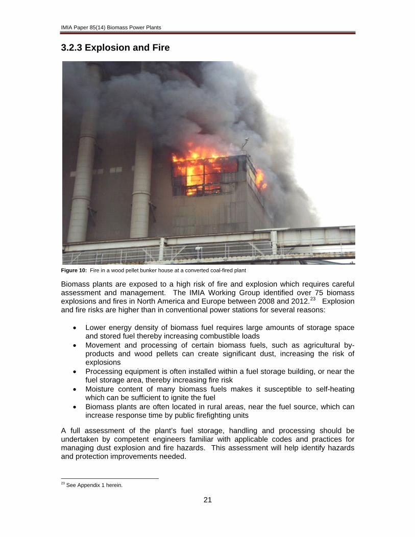
Figure 10: Fire in a wood pellet bunker house at a converted coal-fired plant
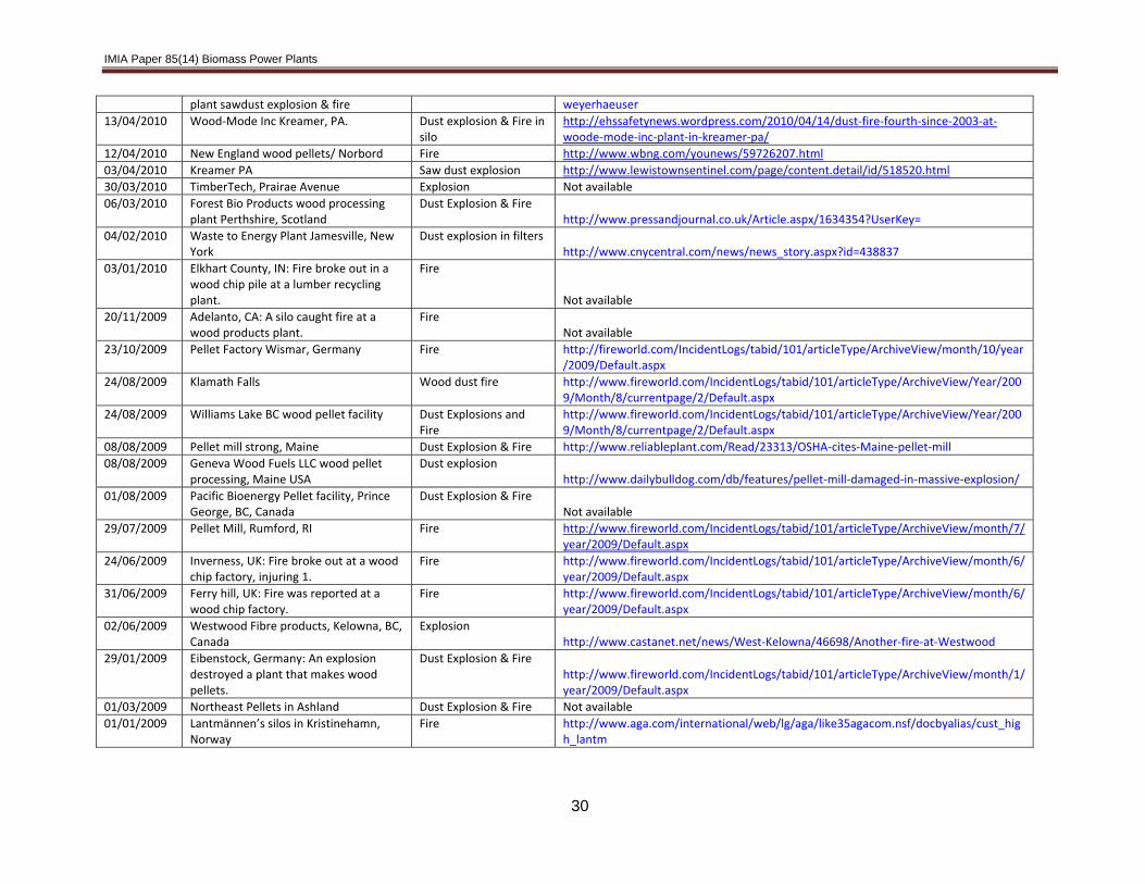
Biomass plants are exposed to a high risk of fire and explosion which requires careful assessment and management. The IMIA Working Group identified over 75 biomass explosions and fires in North America and Europe between 2008 and 2012.23 Explosion and fire risks are higher than in conventional power stations for several reasons:
• Lower energy density of biomass fuel requires large amounts of storage space and stored fuel thereby increasing combustible loads
• Movement and processing of certain biomass fuels, such as agricultural by-products and wood pellets can create significant dust, increasing the risk of explosions
• Processing equipment is often installed within a fuel storage building, or near the fuel storage area, thereby increasing fire risk
• Moisture content of many biomass fuels makes it susceptible to self-heating which can be sufficient to ignite the fuel
• Biomass plants are often located in rural areas, near the fuel source, which can increase response time by public firefighting units
A full assessment of the plant’s fuel storage, handling and processing should be undertaken by competent engineers familiar with applicable codes and practices for managing dust explosion and fire hazards. This assessment will help identify hazards and protection improvements needed. 23 See Appendix 1 herein.
21

IMIA Paper 85(14) Biomass Power Plants
To manage fire and explosion risk biomass plants should:
• Be designed in accordance with National Fire Protection Association (NFPA) 850 – Recommended Practice for Fire Protection for Electricity Generating Plants
• Be constructed from non-combustible materials, including thermal insulation • Protect steel columns within biomass storage areas against structural damage
from heat by using either concrete encasement or a fire protection system • Be designed to minimises surface areas where dust can settle, and allow access
for cleaning all areas • Incorporate appropriate fire segregation by using barriers, spatial separation, fire
isolation devices or other approved means • Utilise fire door assemblies, fire dampers, penetration seals (fire stops), or other
approved means in openings in fire walls with a protection rating consistent with the fire resistance of the barrier
• Maintain sufficient moisture control of biomass feedstock to limit bacterial and fungal growth to control the risk of self heating
• Include appropriate fire protection measures (including automatic sprinklers, detection and alarm systems) and dust control measures in accordance with NFPA guidelines.
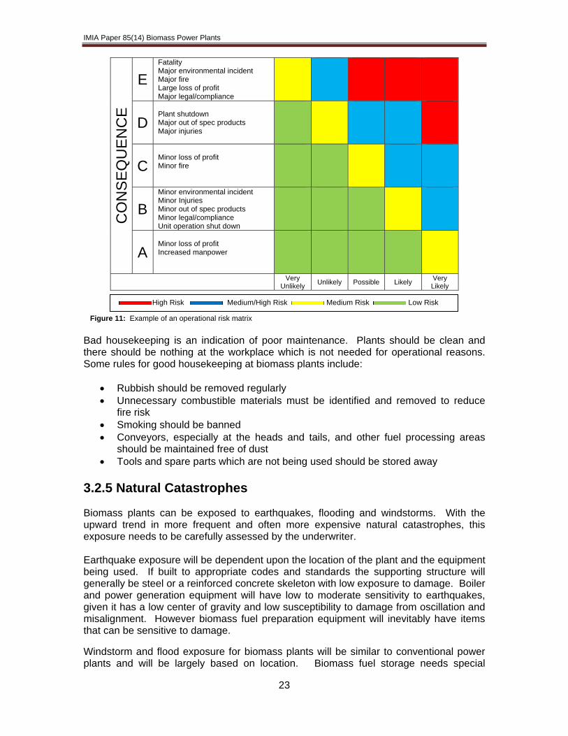
3.2.4 Maintenance and Housekeeping Wear and tear is not covered under insurance, however consequential material damage and loss of profit can be. The conversion of biomass to energy is heavily subsidized and every outage creates the risk of significant loss of profit. Accordingly, a good maintenance regime is an indicator of good risk quality from an underwriting perspective. Quality of maintenance can be difficult to assess as many survey reports do not provide comprehensive information. A sample maintenance checklist with some questions to be asked during site surveys is attached as Appendix 2. A professional maintenance approach consists of different strategies optimized for specific equipment and with a focus on overall plant performance. The maintenance protocol should not be restricted to the equipment but should also address protection systems. During the last few years several turbine losses have been caused by uncontrolled operation due to faulty generator breaker systems. It is important to identify equipment that can cause long shutdowns because of delivery time and bottleneck situations, such as a single line conveyor, the turbine-generator set and high voltage transformers. Individual maintenance strategies must be developed for such equipment. Spare parts should be in stock as part of the strategy. Risk based optimization of maintenance is an approach that allows for proper reaction to unplanned situations. An assessment using a risk matrix prioritises all unplanned works with the aim of shifting those activities into the planned regime. For example, if the assessment of an event is not ‘high risk’ the work can be delayed by 24 hours, which would allow for preparations and rescheduling other works. The risk matrix needs to be calibrated for every plant individually.
22
IMIA Paper 85(14) Biomass Power Plants
CO
NS
EQ
UE
NC
E
E Fatality Major environmental incident Major fire Large loss of profit Major legal/compliance
D Plant shutdown Major out of spec products Major injuries
C Minor loss of profit Minor fire
B Minor environmental incident Minor Injuries Minor out of spec products Minor legal/compliance Unit operation shut down
A Minor loss of profit Increased manpower
Very Unlikely Unlikely Possible Likely Very
Likely
High Risk Medium/High Risk Medium Risk Low Risk Figure 11: Example of an operational risk matrix
Bad housekeeping is an indication of poor maintenance. Plants should be clean and there should be nothing at the workplace which is not needed for operational reasons. Some rules for good housekeeping at biomass plants include:
• Rubbish should be removed regularly • Unnecessary combustible materials must be identified and removed to reduce
fire risk • Smoking should be banned • Conveyors, especially at the heads and tails, and other fuel processing areas
should be maintained free of dust • Tools and spare parts which are not being used should be stored away
3.2.5 Natural Catastrophes Biomass plants can be exposed to earthquakes, flooding and windstorms. With the upward trend in more frequent and often more expensive natural catastrophes, this exposure needs to be carefully assessed by the underwriter. Earthquake exposure will be dependent upon the location of the plant and the equipment being used. If built to appropriate codes and standards the supporting structure will generally be steel or a reinforced concrete skeleton with low exposure to damage. Boiler and power generation equipment will have low to moderate sensitivity to earthquakes, given it has a low center of gravity and low susceptibility to damage from oscillation and misalignment. However biomass fuel preparation equipment will inevitably have items that can be sensitive to damage.
Windstorm and flood exposure for biomass plants will be similar to conventional power plants and will be largely based on location. Biomass fuel storage needs special
23
IMIA Paper 85(14) Biomass Power Plants
consideration for protection from windstorm and water damage, especially for large open air storage areas.
3.3 Financial Risks 3.3.1 Delay in Start-up (DSU) / Advance Loss of Profit (ALOP) DSU and ALOP coverage offered with a Construction All Risk or Erection All Risk policy protects against loss of gross profit arising from a delay in the completion of the project, associated with an indemnifiable material damage loss. In calculating the DSU/ALOP rate and selecting the indemnity period for new and retrofitted biomass plants underwriters need to consider numerous factors.
• Project period (construction and/or erection plus testing if applicable). As a general rule, the longer the project period, the greater the risk for a delay in start-up loss. The construction period for a biomass plant is typically around 12 to 24 months, depending upon size. The specific plant design will also have an impact on the project period. For example, fluidized boiler technology will take longer to build than grate boiler technology. In reviewing the project period, underwriters should assess whether the schedule is aggressive or if sufficient contingency has been built into the plan to allow for potential delays.
• Skill and training of project staff. Biomass projects can have unusual equipment configurations and each plant is different. If the project team is not sufficiently experienced, or is not exclusively dedicated to the project, (i.e. the biomass plant project manager might also be in charge of the overall plant operation) loss minimization capability can be reduced.
• Location of the project. Biomass plants tend to be located near the fuel source, sometimes in remote areas. Underwriters should assess nearby infrastructure (roads, harbors, airports) to evaluate ease of access in the event that shipment of replacements parts is necessary.
• Spare availability/length of time for critical path replacements. Biomass fuel is processed and fed into the boiler along a single critical path, typically with no redundancy. Therefore if a key component of the fuel supply pathway suffers damage, the entire plant will be out of operation. This means that a small material damage loss can potentially cause a long delay. It is therefore important to understand spares availability and estimated lead times, including shipment for all key replacement equipment, to properly assess exposure.
• Availability of fuel supply. Biomass plants are highly dependent on
maintaining adequate and continuous fuel supply. There can be multiple reasons why this might be difficult, including price fluctuations, changed or discontinued subsidy programs or lack of supply (a declining regional timber industry for example). This can be an issue during the loss settlement of a DSU claim. The adjuster will have to verify how realistic the original assumptions were compared to the current situation with respect to fuel procurement, which might have changed during the construction process.
24
IMIA Paper 85(14) Biomass Power Plants
3.3.2 Business Interruption Biomass power plants are less efficient in comparison to fossil fuel plants. The calorific value of the fuel is lower than coal, oil and gas. Maintenance and waste handling can be more costly. Biomass plants can be economically viable for several key reasons: (1) Government financial incentives; (2) they form part of a broader manufacturing process; and (3) they can generate income for disposing waste. While conventional electricity and steam sales will form part of the business interruption exposure (merchant, spot, power purchase agreements) income streams for biomass can be complex. Underwriters should consider the following business interruption exposures and check the extent to which they are covered and, if so, how the exposure can be mitigated. 3.3.2.1 Income Streams
3.3.2.1.1 Government Incentives Government incentives play a big role in the financial viability of biomass power plants. Biomass plants run a regulatory risk in this regard, as a change in policy could have a significant effect on continued economical viability. Government incentives available to biomass plants include the following:
• Carbon Credits. As a carbon neutral method of power generation, biomass plants are commonly eligible for carbon credits. As a result the cost of producing each MW is more economical than a coal fired counterpart. This also allows for preferential dispatch in the merit order, allowing plants to run in base load.
• Tax. Governments often provide tax breaks. The value of these are commonly
less than carbon credits, but work in much the same way. The United Kingdom’s Levy Exception Certificates is an example of such an incentive.
• Financial Guarantees. While carbon credits and tax breaks work in the spot
market, where the price of electricity varies, this still leaves biomass plants susceptible to trading pressures. In periods of increased demand and high prices this has a positive impact on income, but conversely when the opposite happens, profit margins are constrained. Some governments have sought to provide certainty around biomass income by guaranteeing prices over a number of years. This financial certainty allows for long term investment and promotes the construction of biomass plants. In the United Kingdom, the government provides a Contract for Difference where there is a pre-agreed strike price for each MW produced. For example, the plant could receive a strike price £110 per MWh. When prices are greater than this, the margin above the strike price is taken by the government. When the price is lower, the difference is made up by the government. The effect of such mechanisms is to guarantee a definable and predictable income stream.
25
IMIA Paper 85(14) Biomass Power Plants
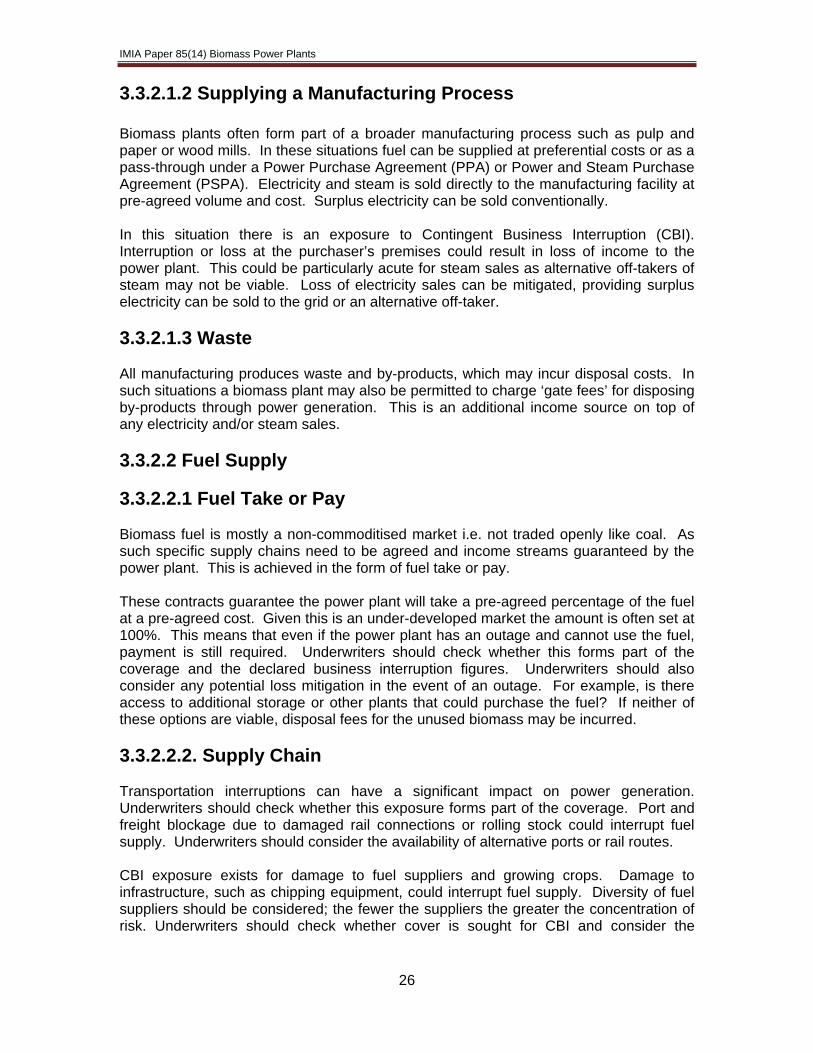
3.3.2.1.2 Supplying a Manufacturing Process Biomass plants often form part of a broader manufacturing process such as pulp and paper or wood mills. In these situations fuel can be supplied at preferential costs or as a pass-through under a Power Purchase Agreement (PPA) or Power and Steam Purchase Agreement (PSPA). Electricity and steam is sold directly to the manufacturing facility at pre-agreed volume and cost. Surplus electricity can be sold conventionally. In this situation there is an exposure to Contingent Business Interruption (CBI). Interruption or loss at the purchaser’s premises could result in loss of income to the power plant. This could be particularly acute for steam sales as alternative off-takers of steam may not be viable. Loss of electricity sales can be mitigated, providing surplus electricity can be sold to the grid or an alternative off-taker. 3.3.2.1.3 Waste All manufacturing produces waste and by-products, which may incur disposal costs. In such situations a biomass plant may also be permitted to charge ‘gate fees’ for disposing by-products through power generation. This is an additional income source on top of any electricity and/or steam sales. 3.3.2.2 Fuel Supply 3.3.2.2.1 Fuel Take or Pay Biomass fuel is mostly a non-commoditised market i.e. not traded openly like coal. As such specific supply chains need to be agreed and income streams guaranteed by the power plant. This is achieved in the form of fuel take or pay. These contracts guarantee the power plant will take a pre-agreed percentage of the fuel at a pre-agreed cost. Given this is an under-developed market the amount is often set at 100%. This means that even if the power plant has an outage and cannot use the fuel, payment is still required. Underwriters should check whether this forms part of the coverage and the declared business interruption figures. Underwriters should also consider any potential loss mitigation in the event of an outage. For example, is there access to additional storage or other plants that could purchase the fuel? If neither of these options are viable, disposal fees for the unused biomass may be incurred. 3.3.2.2.2. Supply Chain Transportation interruptions can have a significant impact on power generation. Underwriters should check whether this exposure forms part of the coverage. Port and freight blockage due to damaged rail connections or rolling stock could interrupt fuel supply. Underwriters should consider the availability of alternative ports or rail routes. CBI exposure exists for damage to fuel suppliers and growing crops. Damage to infrastructure, such as chipping equipment, could interrupt fuel supply. Diversity of fuel suppliers should be considered; the fewer the suppliers the greater the concentration of risk. Underwriters should check whether cover is sought for CBI and consider the
26

IMIA Paper 85(14) Biomass Power Plants
27
implications of an interruption. Mitigation can come in the form of fuel stock stored elsewhere and additional capacity from other suppliers. CBI could extend to insuring growing crops. Many crops grown for biomass have a maturity period, some lasting several years. Storm, flood and disease could destroy growing crops and this could impair a supplier’s ability to provide fuel. Although there is no history of transportation restrictions for biomass, the possibility exists that governments could restrict the entry of foreign biomass fuel from a country that has cases of agricultural/crop disease. 3.3.2.2.3 Extended Business Interruption Biomass plants are bespoke in the technology used and underwriters should consider the impact this could have on the duration of a business interruption loss. Non-conventional equipment may have longer lead times following failure. This loss can be mitigated by comprehensive sparing and disaster recovery plans. Potential Exposure Potential Coverage Conventional Income Merchant, Spot, Tolling, PPAs,
Availability etc. Gross Profit/Gross Revenue
Carbon Credits Generally not covered as allowance is not affected by a loss – can impact on profitability
N/A
Tax Direct impact on profitability Gross Profit/Gross Revenue Financial Guarantees Important mechanism which
provides certainty of income for underwriters
Gross Profit/Gross Revenue
Customers’ Exposure Damage to customers’ premises resulting in loss of revenue
CBI
Fuel Take or Pay Requirement to continue to purchase fuel following loss at a plant
Additional/Increased Costs of Working
Supply Chain Exposure
Damage to suppliers or supply chain constraining fuel supply
CBI/Port blockage/Identifiable disease
Figure 12: Business interruption matrix
4.0 Conclusion Biomass fuel is increasingly being used to replace or supplement fossil fuels in power generation. While much of the technology and equipment used to fire fossil and biomass fuel is the same, the distinctive characteristics of biomass will have a significant impact on the design, operation and performance of a plant. Due to the wide variation in biomass fuel types and usage, each plant is unique and will require full engineering analysis to properly assess and underwrite the risk.

IMIA Paper 85(14) Biomass Power Plants
5.0 Appendices Appendix 1 – Biomass Fires and Explosions: 2008-2012 Date Facility Details of Incident Internet Ref: Active as of August 2014
12/08/2012 810MW Avedore power plant in Copenhagen
Fire on conveyors http://www.canadianbiomassmagazine.ca/content/view/3583/57/
03/08/2012 Green Circle Bio‐Energy's wood pellet facility Panama
spontaneous combustion http://www.canadianbiomassmagazine.ca/content/view/3550/57/
24/06/2012 Jaffrey Wood pellet plant, New England, USA
Fire (fourth since 2008) http://industrialfireprevention.blogspot.co.uk/2012/05/pellet‐plant‐facing‐osha‐fine‐on‐fire.html
11/06/2012 Wood Pellet Co. plant in Ferris Ave, Rumford, East Province, RI, USA
Fire http://patch.com/rhode‐island/eastprovidence/conveyer‐belt‐fire‐closes‐pellet‐production‐business
11/06/2012 Amagerværket, Vattanfall, Denmark Explosion http://ing.dk/artikel/129164‐eksplosion‐skete‐under‐rensning‐af‐silo
02/05/2012 Wood pellet warehouse Port of Panama Fire on conveyors http://www.wmbb.com/story/18125604/panama‐city‐firefi 27/04/2012 New England wood pellet plant, Jaffrey,
New England, Canada Fire
http://www.unionleader.com/article/20120427/NEWS07/120429861
23/04/2012 Lakeland Mill Vancouver Explosion & Fire (fatalities)
http://news.nationalpost.com/2012/04/28/fatal‐sawdust‐blast‐in‐b‐c‐comes‐after‐five‐explsions‐at‐similar‐plants‐since‐2009/
04/03/2012 Upper Leacock silo fire, Ironstone Mills, East Lampeter, PA, USA
Fire http://www.witmerfire.com/fullstory.php?157763
08/03/2012 Laurinburg wood pellet mill, Laurinburg, NC Canada
Dust Explosion & Fire http://www.carolinalive.com/news/story.aspx?id=728305
27/02/2012 Tilbury biomass power station, UK Fire http://www.guardian.co.uk/uk/2012/feb/27/firefighters‐essex‐power‐station‐blaze
23/02/2012 Geneva wood pellet Mill, Strong, Franklin County
Fire http://www.centralmaine.com/2012/02/24/mill‐damaged‐in‐fire‐expected‐to‐reopen‐soon_2012‐02‐23/
21/01/2012 Babine Forest Products mill injuring 19, Burns Lake BC
Explosion http://www.cbc.ca/news/canada/british‐columbia/babine‐forest‐products‐fined‐1m‐for‐burns‐lake‐sawmill‐explosion‐1.2597280
01/01/2012 Wood‐pellet manufacturing plant , Wiggins MS
Fire http://www.fireworld.com/IncidentLogs/tabid/101/articleType/ArchiveView/Year/2012/Month/1/currentpage/8/Default.aspx
21/12/2011 Pinnacle Plant Houston BC, Canada. (several fires since 2006)
Fire http://www.cftktv.com/news/Story.aspx?ID=1630036
31/10/2011 Storage area Port of Tyne, UK Fire http://www.journallive.co.uk/north‐east‐news/todays‐news/2011/10/31/firefighters‐battle‐huge‐biomass‐fire‐at‐port‐of‐tyne‐61634‐29689277/
30/11/2011 Kremmling Pellet Plant, Colorado Fire http://www.skyhidailynews.com/article/20111130/NEWS/111139999
20/10/2011 New England wood pellet plant, Jaffrey, New Hampshire, USA
Dust Explosion & Fire http://www.unionleader.com/article/20111020/NEWS07/710219950/0/FRONTPAGE
20/07/2011 Waycross, Jacksonville, Georgia, USA (incident after 1 month operation)
Explosion http://jacksonville.com/news/crime/2011‐06‐21/story/explosion‐damages‐waycross‐plant‐no‐injuries‐reported
28

IMIA Paper 85(14) Biomass Power Plants
27/04/2011 Pinnacle Plant Houston BC, Canada. (several fires since 2006)
Dust Explosion & Fire Not available
04/04/2011 Armstrong pellet plant, Pleasant Valley Road, Swan Lake , Canada
Dust Explosion & Fire http://www.castanet.net/news/Vernon/61203/Blast‐fire‐at‐Armstrong‐Pellets‐plant
04/04/2011 Pinnacle Pellet, Williams Lake, BC Fire http://welcometowilliamslake.ca/index.php/the‐news/local‐news/3414‐pinnacle‐pellet‐fire.html
10/03/2011 Pacific Bioenergy Pellet facility, Prince George, BC, Canada
Fire http://www.canadianbiomassmagazine.ca/content/view/2352/57/
28/02/2011 Portsmouth, NH: A fire in a wood chip crushing machine spread through a power
Fire http://www.fosters.com/apps/pbcs.dll/article?AID=/20110301/GJNEWS_01/703019953/‐1/FOSNEWS
06/01/2011 Tolko Soda Creek Mill, Williams Lake Dust Explosion & Fire http://www.vancouversun.com/news/sawmill+blast+went+unreported/6550344/story.html
17/12/2010 Pacific Bioenergy Pellet facility, Prince George, BC, Canada
Dust Explosion & Fire http://forestindustries.eu/content/explosion‐pacific‐bioenergy%E2%80%99s‐pellet‐plant‐prince‐george‐bc
16/12/2010 Wood‐pellet factory in Barnstead, NH, USA (2 in a week)
Fire http://www.firehouse.com/news/10464625/nh‐firefighters‐again‐called‐to‐wood‐pellet‐plant
07/12/2010 Michigan Fuel pellet plant, Holland, Michigan USA
Fire http://www.hollandsentinel.com/news/x1171015614/Fire‐starts‐in‐machinery‐at‐wood‐pellet‐plant
02/12/2010 The Ainsworth Lumber Co. Ltd.‘s OSB plant, Mile House BC Canada
Dust Explosion & Fire Not available
09/11/2010 Havco wood products , Scott County, MO
Fire http://www.kfvs12.com/story/13475742/another‐fire‐at‐havco‐wood‐products‐overnight
18/11/2010 Ainsworth OSB Plant 100 Miles House British Columbia
Explosion http://foresttalk.com/index.php/2010/11/18/ainsworth‐osb‐plant‐in‐100‐mile‐house‐still‐down‐after‐last‐weeks‐explosion/
25/10/2010 CJSC Holding Company Pinskdrev, Belarus
Dust Explosion & Fire http://charter97.org/en/news/2010/10/26/33260/
10/09/2010 Pine Bluff Fibre resources wood pellet facility, Maryland USA
Dust explosion &Fire http://www.chem.info/News/2010/09/Safety‐Sawdust‐Explosion‐Fire‐Guts‐Plant/
08/09/2010 Enligna Canada’s wood pellet mill Upper Musquodoboit Halifax Nova Scotia
Fire http://www.canadianbiomassmagazine.ca/content/view/1935/57/
28/06/2010 South Molton, UK: wood processing factory.
Fire http://www.edp24.co.uk/news/fire_at_south_molton_chipboard_factory_1_430441
07/09/2010 Mingo County, WV: Fire broke out in a wood processing plant.
Wood dust fire in ventilation Not available
18/07/2010 Lakeshore Wisconsin wood pallets and wood pellets
Fire http://www.jsonline.com/news/wisconsin/99535874.html
23/04/2010 Creative Biomass, Kimble Place, Fitchburg , Biomass silo
Dust Explosion & Fire in silo http://lifeasajournalist.blogspot.co.uk/2010/06/nobody‐hurt‐in‐dust‐explosion.html
21/04/2010 Wayerhaeuser, Grande Prayerie‐ pulp Fire http://www.dailyheraldtribune.com/2010/04/21/friction‐sawdust‐start‐fire‐at‐
29
IMIA Paper 85(14) Biomass Power Plants
plant sawdust explosion & fire weyerhaeuser
13/04/2010 Wood‐Mode Inc Kreamer, PA. Dust explosion & Fire in silo
http://ehssafetynews.wordpress.com/2010/04/14/dust‐fire‐fourth‐since‐2003‐at‐woode‐mode‐inc‐plant‐in‐kreamer‐pa/
12/04/2010 New England wood pellets/ Norbord Fire http://www.wbng.com/younews/59726207.html
03/04/2010 Kreamer PA Saw dust explosion http://www.lewistownsentinel.com/page/content.detail/id/518520.html
30/03/2010 TimberTech, Prairae Avenue Explosion Not available 06/03/2010 Forest Bio Products wood processing
plant Perthshire, Scotland Dust Explosion & Fire
http://www.pressandjournal.co.uk/Article.aspx/1634354?UserKey=
04/02/2010 Waste to Energy Plant Jamesville, New York
Dust explosion in filters http://www.cnycentral.com/news/news_story.aspx?id=438837
03/01/2010 Elkhart County, IN: Fire broke out in a wood chip pile at a lumber recycling plant.
Fire
Not available 20/11/2009 Adelanto, CA: A silo caught fire at a
wood products plant. Fire
Not available 23/10/2009 Pellet Factory Wismar, Germany Fire http://fireworld.com/IncidentLogs/tabid/101/articleType/ArchiveView/month/10/year
/2009/Default.aspx
24/08/2009 Klamath Falls Wood dust fire http://www.fireworld.com/IncidentLogs/tabid/101/articleType/ArchiveView/Year/2009/Month/8/currentpage/2/Default.aspx
24/08/2009 Williams Lake BC wood pellet facility Dust Explosions and Fire
http://www.fireworld.com/IncidentLogs/tabid/101/articleType/ArchiveView/Year/2009/Month/8/currentpage/2/Default.aspx
08/08/2009 Pellet mill strong, Maine Dust Explosion & Fire http://www.reliableplant.com/Read/23313/OSHA‐cites‐Maine‐pellet‐mill
08/08/2009 Geneva Wood Fuels LLC wood pellet processing, Maine USA
Dust explosion http://www.dailybulldog.com/db/features/pellet‐mill‐damaged‐in‐massive‐explosion/
01/08/2009 Pacific Bioenergy Pellet facility, Prince George, BC, Canada
Dust Explosion & Fire Not available
29/07/2009 Pellet Mill, Rumford, RI Fire http://www.fireworld.com/IncidentLogs/tabid/101/articleType/ArchiveView/month/7/year/2009/Default.aspx
24/06/2009 Inverness, UK: Fire broke out at a wood chip factory, injuring 1.
Fire http://www.fireworld.com/IncidentLogs/tabid/101/articleType/ArchiveView/month/6/year/2009/Default.aspx
31/06/2009 Ferry hill, UK: Fire was reported at a wood chip factory.
Fire http://www.fireworld.com/IncidentLogs/tabid/101/articleType/ArchiveView/month/6/year/2009/Default.aspx
02/06/2009 Westwood Fibre products, Kelowna, BC, Canada
Explosion http://www.castanet.net/news/West‐Kelowna/46698/Another‐fire‐at‐Westwood
29/01/2009 Eibenstock, Germany: An explosion destroyed a plant that makes wood pellets.
Dust Explosion & Fire http://www.fireworld.com/IncidentLogs/tabid/101/articleType/ArchiveView/month/1/year/2009/Default.aspx
01/03/2009 Northeast Pellets in Ashland Dust Explosion & Fire Not available 01/01/2009 Lantmännen’s silos in Kristinehamn,
Norway Fire http://www.aga.com/international/web/lg/aga/like35agacom.nsf/docbyalias/cust_hig
h_lantm
30

IMIA Paper 85(14) Biomass Power Plants
31
04/01/2009 Pellet Facility Ettenheim, Germany Dust Explosion http://dustexplosions.blogspot.com/2009/01/staubexplosion‐german‐pellet‐mill.html19/12/2008 Pacific Bioenergy Pellet facility, Prince
George, BC, Canada Dust Explosion & Fire http://forestindustries.eu/content/explosion‐pacific‐bioenergy%E2%80%99s‐pellet‐
plant‐prince‐george‐bc
01/12/2008 Ontario Power generation, Atikokan ON (page 16 of pdf reference)
Explosion http://www.pellet.org/linked/2011‐07‐24%20g%20murray%20pfi.pdf
18/09/2008 Granulles de lac Mauricie, Atikokan, ON (page 16 of pdf reference)
Fire http://www.pellet.org/linked/2011‐07‐24%20g%20murray%20pfi.pdf
17/09/2008 Kremmling Pellet Plant, Colorado Fire http://www.skyhidailynews.com/article/20081027/NEWS/810289971
08/10/2008 New England Wood Pellets Dust Explosion & Fire http://dustexplosions.blogspot.com/2008/08/wood‐pellet‐dust‐fire‐non‐issue.html
22/08/2008 AJ Stove and Pellets in Marion, PA Dust Explosion http://dustexplosions.blogspot.com/2008/08/wood‐pellet‐plant‐dust‐explosion‐again.html
15/08/2008 Corinth Wood Pellets Dust Explosion & Fire http://dustexplosions.blogspot.com/2008/08/wood‐pellet‐dust‐fire‐non‐issue.html
11/08/2008 New England Pellet Plant Jaffrey pellet plant New Hampshire
Dust Explosion & Fire Not available
15/07/2008 AJ Stove and Pellets in Marion, PA Dust Explosion http://dustexplosions.blogspot.com/2008/08/wood‐pellet‐plant‐dust‐explosion‐again.html
01/07/2008 Westwood Fibre products, Kelowna, BC, Canada (see bottom of ref)
Dust Explosion & Fire http://www.castanet.net/news/West‐Kelowna/46698/Another‐fire‐at‐Westwood
21/06/2008 Vancouver, B.C. Fire http://www.fireworld.com/IncidentLogs/tabid/101/articleType/ArchiveView/Year/2009/Month/8/currentpage/2/Default.aspx
20/06/2008 Pellet Mill, Corinth, Maine Fire http://woodpelletguru.blogspot.co.uk/2008/05/pellet‐mill‐fire.html
01/03/2008 Pacific Bioenergy Pellet facility, Prince George, BC, Canada
Fire http://www.princegeorgecitizen.com/article/20101218/PRINCEGEORGE0101/312189993/‐1/PRINCEGEORGE/explosion‐closes‐down‐pellet‐plant
20/05/2008 Corinth Wood Pellets Dust Explosion & Fire http://dustexplosions.blogspot.com/2008/08/wood‐pellet‐dust‐fire‐non‐issue.html
31/03/2008 Pacific Bioenergy Pellet facility, Prince George, BC, Canada
Dust Explosion & Fire Not available
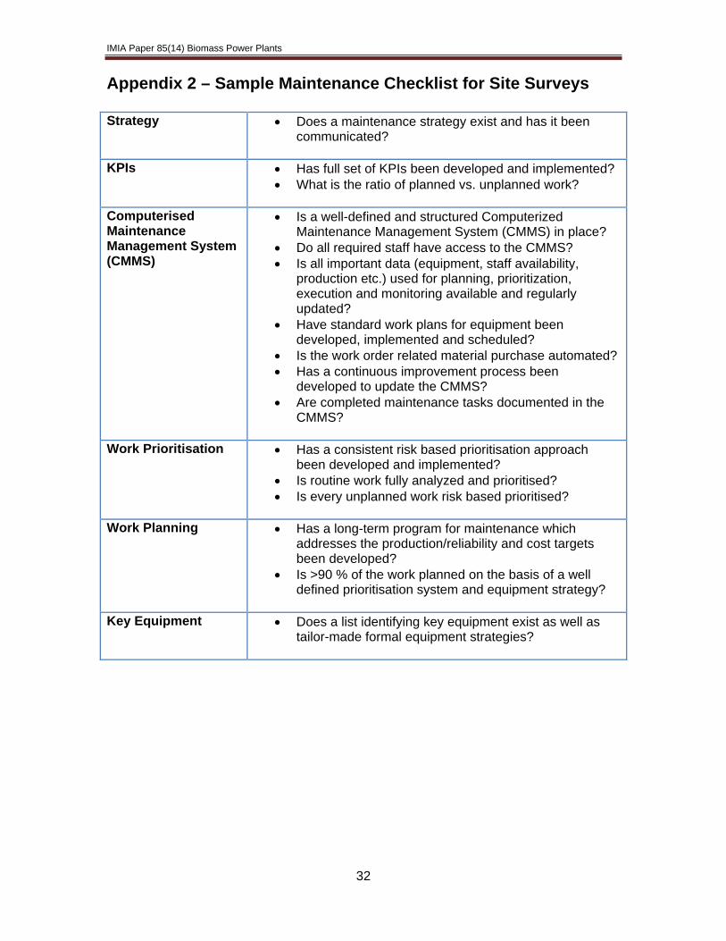
IMIA Paper 85(14) Biomass Power Plants
Appendix 2 – Sample Maintenance Checklist for Site Surveys Strategy • Does a maintenance strategy exist and has it been
communicated?
KPIs • Has full set of KPIs been developed and implemented? • What is the ratio of planned vs. unplanned work?
Computerised Maintenance Management System (CMMS)
• Is a well-defined and structured Computerized Maintenance Management System (CMMS) in place?
• Do all required staff have access to the CMMS? • Is all important data (equipment, staff availability,
production etc.) used for planning, prioritization, execution and monitoring available and regularly updated?
• Have standard work plans for equipment been developed, implemented and scheduled?
• Is the work order related material purchase automated? • Has a continuous improvement process been
developed to update the CMMS? • Are completed maintenance tasks documented in the
CMMS?
Work Prioritisation • Has a consistent risk based prioritisation approach been developed and implemented?
• Is routine work fully analyzed and prioritised? • Is every unplanned work risk based prioritised?
Work Planning • Has a long-term program for maintenance which
addresses the production/reliability and cost targets been developed?
• Is >90 % of the work planned on the basis of a well defined prioritisation system and equipment strategy?
Key Equipment • Does a list identifying key equipment exist as well as
tailor-made formal equipment strategies?
32

IMIA Paper 85(14) Biomass Power Plants
Appendix 3 – Sample Underwriting Risk Assessment Guide Risk Assessment Category
Technical Requirements/Considerations
Technology, Process and Key Items
• Details of process, technology and key items: combustion system/boiler/steam generator and power generation assets (steam turbine, generator, transformers)
• For all key items establish: manufacturer, model, rating output/capacity and age
• Unusual features - prototype or unproven technology or processes? • Up-scaling - has this type of plant/process successfully operated on same
scale before? • Is plant built/designed for specified fuel type? • Has it been modified/retrofitted to run on biomass feedstock? If so, consider
if boiler design and/or materials used are fit for purpose for operating conditions
Fuel and Feedstock
• Type of fuel and characteristics such as size and moisture content • Receiving and storage: is fuel storage location and handling method
appropriate for the feedstock (storage/throughput time, quantities, height of stockpiles, distance from buildings or other assets, physical protections, ventilation and moisture control, weather protections)?
• For raw fuel types requiring preparation, are controls in place to properly screen and process to remove and/or prevent foreign bodies?
• Is appropriate temperature monitoring/heat detection in place? • Are handling and transfer system(s), including fire detection and
suppression appropriate? Explosion and Fire Protection
• Have NFPA recommendations been followed? • Is there appropriate separation: adequate distance between buildings and
fuel storage area (adequacy of fire walls/barrier)? • Type and extent of automatic detection systems in fuel storage areas,
transfer systems, and within process buildings • Manual facilities and automatic suppression systems - are suppression and
deluge systems sufficient? • What are the activation and fire service response times and water supplies? • Are maintenance and service contracts for the automatic fire protection
systems in place? Site and Building • Overall site plan and layout
• Assessment of natural hazards and protections • Site security arrangements • Building(s) construction standards • Proportion of combustible to non-combustible materials
Construction/EAR • Fire controls during construction period (prior to facility fire protections becoming functional/activated) - JCOP - Fire Prevention or similar
• Quality of overall site management • Testing & Commissioning issues: nature of tests, experience and
management of testing team • If fuel is on site at for testing and commissioning, is fire protection
operational? Operational • Experience/engineering expertise to run the type of plant?
• Warranties: main provisions, equipment covered, expiry dates • Maintenance regime: who is responsible, what is the frequency and extent
of routine maintenance? • Availability and functioning of monitoring systems (e.g. SCADA system
providing temperature and vibration monitoring and predictive maintenance analysis)
• Key plant spares, location and condition of spares • Lead times for repair or replacement of key items which are not spared? • Previous losses; when, causation, circumstances and lessons learned
33

IMIA Paper 85(14) Biomass Power Plants
34
6.0 Other References American Council on Renewable Energy: http://www.acore.org/ Biomass Magazine: http://www.biomassmagazine.com/ Biomass Power Association: http://www.usabiomass.org/index.php Clair, L. & Fordham, P. Biomass: An Emerging Fuel for Power Generation. Power Engineering Magazine. November 2009. Creamers, M. IEA Bioergy Task 32 Biomass Combustion and Cofiring. August 2009. German Insurance Association. Renewable Energies. March 2010. National Renewable Energy Laboratory: http://www.nrel.gov/ Neville, A. Biomass Cofiring: A Promising New Generation Option. April 2011. The Beck Group. Coyote Springs Biomass Power Feasibility Study. June 2011. US Department of Energy Bioenergy Technologies Office: http://www.energy.gov/eere/bioenergy/bioenergy-technologies-office


![IMIA Working Group Paper [WGP 90 (15)] IMIA Annual Conference ...](https://static.fdocuments.in/doc/165x107/586678171a28ab54408b48b1/imia-working-group-paper-wgp-90-15-imia-annual-conference-.jpg)