Image Compression Black Book3
73
Selective image compression 1
-
Upload
swapneelchitale -
Category
Documents
-
view
242 -
download
0
Transcript of Image Compression Black Book3

8/8/2019 Image Compression Black Book3
http://slidepdf.com/reader/full/image-compression-black-book3 1/73
Selective image compression
1
8/8/2019 Image Compression Black Book3
http://slidepdf.com/reader/full/image-compression-black-book3 2/73
Selective image compression
INTRODUCTION
Advances over the past in many aspects of digital technology especially devices for
image acquisition data storage and bitmapped printing and display have brought
about many applications of digital imaging. With the possible exception of
facsimile, digital image are not commonplace in general purpose computing system
the way the text and geometric graphics are. The key obstacle for many applications
is the vast amount of data required to represent a digital image directly. Use of
digital images often is not viable due to high storage or transmission costs, even
when image capture and display devices are quite affordable.
In today’s digital world, when we see digital movie, listen digital music, read digital
mail, store documents digital making conversation digitally, we have to deal with
huge amount of digital data. So, data compression plays a very significant role to
keep the digital world realistic. If there were no data compression techniques, we
would have not been able to listen songs over the Internet, see digital pictures or
movies, or we would have not heard about video conferencing or telemedicine.
How data compression made it possible? What are the main advantages of data
compression in digital world? There may be many answers but the three obvious
reasons are the saving of memory space for storage, channel bandwidth and the
processing time for transmission. Every one of us might have experienced that
before the advent MP3, hardly 4 or 5 songs of wav file could be accommodated.
And it was not possible to send a wav file through mail because of its tremendous
file size. Also, it took 5 to 10 minutes or even more to download a song from theInternet.
Now, we can easily accommodate 50 to 60 songs of MP3 in a music CD of same
capacity. Because, the uncompressed audio files can be compressed 10 to 15 times
using MP3 format. And we have no problem in sending any of our favorite music to
our distant friends in any corner of the world. Also, we can download a song in
MP3 in a matter of seconds. This is a simple example of significance of data
2
8/8/2019 Image Compression Black Book3
http://slidepdf.com/reader/full/image-compression-black-book3 3/73
Selective image compression
compression. Similar compression schemes were developed for other digital data
like images and videos. Videos are nothings but the animations of frames of images
in a proper sequence at a rate of 30 frames per second or higher. A huge amount of
memory is required for storing video files. The possibility of storing 4/5 movies inDVD CD now rather than we used 2/3 CDs for a movie file is because compression.
We will consider here mainly the image compression techniques.
Images require substantial storage and transmission resources, thus image
compression is advantageous to reduce these requirements. The report covers some
background of wavelet analysis, data compression and how wavelets have been and
can be used for image compression. An investigation into the process and problemsinvolved with image compression was made and the results of this investigation are
discussed.
This rapid development of imaging technologies has generated great interest in
efficient compression methods. Image compression can significantly help by
reducing these data storage requirements. This in turn, enables faster transmission
of image and it can also provide data security. Moreover, it makes possible the
development of efficient image processing algorithm that needs less processing time
by working directly with the compressed data.
3
8/8/2019 Image Compression Black Book3
http://slidepdf.com/reader/full/image-compression-black-book3 4/73
Selective image compression
IMAGE COMPRESSION
Advance medical imaging requires storage of large quantities of digitized clinical
data. Due to the bandwidth and storage limitations, medical images must he
compressed before transmission and storage ,. However, the compression will
reduce the image fidelity, especially when the images are compressed at lower bit
rates. The reconstructed images suffer from blocking artifacts and the quality of the
image will be severely degraded under the circumstances of high compression ratio
which shown by JPEG standard.
In recent years, much of the research activities in image coding have been focused
on the discrete wavelet transform (DWT) as the overlapping nature of the transform
alleviates blocking artifacts, while the multiresolution character of the wavelet
decomposition leads to superior energy compaction and perceptual quality of the
decompressed image. Furthermore, the multiresolution transform domain means
that wavelet compression methods degrade much more gracefully than block-DCT
methods as the compression ratio increase.
This introduction has meant that for the first time the discrete wavelet transform is
to be used for the decomposition and reconstruction of images together with an
efficient coding scheme. The aim of multiresolution analysis is simultaneous image
representation on different resolution level. This kind of representation is well
suited to the properties of Human Visual System (HVS) . Over the last decade or so,
wavelets have had a growing impact on signal processing theory and practice, both
because of their unifying role and their successes in various applications. Filter banks, which lie at the heart of wavelet-based algorithms, have become standard
signal processing operators, used routinely in applications ranging from
compression to modems. The contributions of wavelets have often been in the
subtle interplay between discrete-time and continuous-time signal processing.
Wavelet transform represents an image as a sum of wavelet functions (wavelets)
with different locations and scales. Basis for wavelet transform can be composed of
any function that satisfies requirements of multiresolution analysis, it means that
4
8/8/2019 Image Compression Black Book3
http://slidepdf.com/reader/full/image-compression-black-book3 5/73
Selective image compression
there exits a large selection of wavelet families depending on the choice of wavelet
function. The topic of multiresolution and wavelet transforms has received a great
deal of attention in recent years. Wavelet transforms are important because they
provide a means for localization of signals in both frequency and time . This leads tomany applications such as signal analys is image compression and applied
mathematics0. Among the most popular wavelets are Haar, Daubechies, coiflet and
biorthogonal, etc. The main purpose of this paper is to investigate the impact and
quality of orthogonal wavelet filter for SPIHT. Meanwhile, we also look into the
effect of the level of wavelet decomposition towards compression efficiency as in .
The compression simulations are done on some images. The qualitative andquantitative results of these simulations are presented. Wavelet methods involve
overlapping transforms with varying-length basis functions. This overlapping nature
of the transform alleviates blocking artifacts, while the multiresolution character of
the wavelet decomposition leads to superior energy compaction and perceptual
quality of the decompressed image. The compression simulations are done on few
images. The qualitative and quantitative results of these simulations are presented .
5
8/8/2019 Image Compression Black Book3
http://slidepdf.com/reader/full/image-compression-black-book3 6/73
Selective image compression
6
8/8/2019 Image Compression Black Book3
http://slidepdf.com/reader/full/image-compression-black-book3 7/73
Selective image compression
LITERATURE REVIEW
Often signals we wish to process are in the time-domain, but in order to process
them more easily other information, such as frequency, is required. Mathematical
transforms translate the information of signals into different representations. For
example, the Fourier transform converts a signal between the time and frequency
domains, such that the frequencies of a signal can be seen. However the Fourier
transform cannot provide information on which frequencies occur at specific times
in the signal as time and frequency are viewed independently. To solve this problem
the Short Term Fourier Transform (STFT) introduced the idea of windows through
which different parts of a signal are viewed. For a given window in time the
frequencies can be viewed.
However Heisenburg.s Uncertainty Principle states that as the resolution of the
signal improves in the time domain, by zooming on different sections, the frequency
resolution gets worse. Ideally, a method of multiresolution is needed, which allows
certain parts of the signal to be resolved well in time, and other parts to be resolved
well in frequency.The topic of multiresolution and wavelet transforms has receiveda great deal of attention in recent years. Wavelet transforms are important because
they provide a means for localization of signals in both frequency and time . This
leads to many applications such as signal analysis, image compression and applied
mathematics.
The power and magic of wavelet analysis is exactly this multiresolution. Images
contain large amounts of information that requires much storage space, largetransmission bandwidths and long transmission times. Therefore it is advantageous
to compress the image by storing only the essential information needed to
reconstruct the image. An image can be thought of as a matrix of pixel (or intensity)
values. In order to compress the image, redundancies must be exploited, for
example, areas where there is little or no change between pixel values. Therefore
images having large areas of uniform colour will have large redundancies, and
conversely images that have frequent and large changes in colour will be less
redundant and harder to compress.
7
8/8/2019 Image Compression Black Book3
http://slidepdf.com/reader/full/image-compression-black-book3 8/73
Selective image compression
Wavelet analysis can be used to divide the information of an image into
approximation and detail subsignals. The approximation subsignal shows the
general trend of pixel values, and three detail subsignals show the vertical,horizontal and diagonal details or changes in the image. If these details are very
small then they can be set to zero without significantly changing the image. The
value below which details are considered small enough to be set to zero is known as
the threshold. The greater the number of zeros the greater the compression that can
be achieved.
The amount of information retained by an image after compression anddecompression is known as the energy retained and this is proportional to the sum
of the squares of the pixel values. If the energy retained is 100% then the
compression is known as .lossless., as the image can be reconstructed exactly. This
occurs when the threshold value is set to zero, meaning that the detail has not been
changed. If any values are changed then energy will be lost and this is known as
lossy compression. Ideally, during compression the number of zeros and the energy
retention will be as high as possible.
However, as more zeros are obtained more energy is lost, so a balance between the
two needs to be found. The first part of the report introduces the background of
wavelets and compression in more detail. This is followed by a review of a practical
investigation into how compression can be achieved with wavelets and the results
obtained. The purpose of the investigation was to find the effect of the
decomposition level, wavelet and image on the number of zeros and energy
retention that could be achieved.
8
8/8/2019 Image Compression Black Book3
http://slidepdf.com/reader/full/image-compression-black-book3 9/73
Selective image compression
9
8/8/2019 Image Compression Black Book3
http://slidepdf.com/reader/full/image-compression-black-book3 10/73
Selective image compression
PROBLEM DEFINITION
In certain applications, a large portion of the data traffic over the network comprises
of the transmission of digital images for various commercial purpose taking up a
considerable amount of time. Thus we decided to generate a new compression
algorithm, which focuses on a simple concept of “Wavelet Based Technique which
first decomposes an image hierarchically into oriented sub bands and then encodes
the wavelet coefficients using a zero-tree data.” This compressed data would also
reduce the amount of data traffic over the network.
Hence, our problem can be defined as follows:-
“To develop a software for compressing the image files by using the wavelet
decomposition method for image compression.”
10

8/8/2019 Image Compression Black Book3
http://slidepdf.com/reader/full/image-compression-black-book3 11/73
Selective image compression
11
8/8/2019 Image Compression Black Book3
http://slidepdf.com/reader/full/image-compression-black-book3 12/73
Selective image compression
OBJECTIVES
To develop an algorithm that would compress the image file with a high
compression ratio.
It should support more number of image formats.
It should provide considerable savings in storage space.
It should keep the selected portion of image as it is, while compressing the
rest of the image.
Use of different wavelets for compression
12
8/8/2019 Image Compression Black Book3
http://slidepdf.com/reader/full/image-compression-black-book3 13/73
Selective image compression
13
8/8/2019 Image Compression Black Book3
http://slidepdf.com/reader/full/image-compression-black-book3 14/73
Selective image compression
WAVELET TRANSFORM
Wavelet transform (WT) represents image as a sum of wavelets on different
resolution levels. A wavelet is a (ideally) compact function, i.e., outside a certain
interval it vanishes. Implementations are based on the fast wavelet transform, where
a given wavelet (mother wavelet) is shifted and dilated so as to provide a base in the
function space. In other words, a one-dimensional function is transformed into a
twodimensional space, where it is approximated by coefficients that depend on time
(determined by the translation parameter) and on scale, (determined by the dilation
parameter). The zoom phenomena of the WT offer high temporal localization for
high frequencies while offering good frequency resolution for low frequencies.
Consequently, the WT is especially well suited to analyze local variations such as
those in still images. Multiresolution analysis is implemented via high-pass filters
(wavelets) and low-pass filters (scaling functions).
In this context, the wavelet transform of a signal or image can be realized by means
of a filter bank via successive application of a 2-channel filter bank consisting of
high-pass and low-pass filters: the detail coefficients (from High Pass Filter) of
every iteration step are kept apart, and the iteration starts again with the remaining
approximation coefficients (from Low Pass Filter) of the transform as in .
One of the first efficient wavelet image coders reported in the literature is the
EZW . It is based on the construction of coefficient-trees and successive-
approximations, that can be implemented as bit-plane processing. Due to its
successive-approximation nature, it is SNR scalable, although at the expensive of
sacrificing spatial scalability. SPIHT is an advanced version of this algorithm,
where coefficient-trees are processed in a more efficient way. Both algorithms need
the computation of coefficient-trees and perform different iterations focusing on a
different bit plane in each iteration, what usually requires high computational
complexity .
14
8/8/2019 Image Compression Black Book3
http://slidepdf.com/reader/full/image-compression-black-book3 15/73
Selective image compression
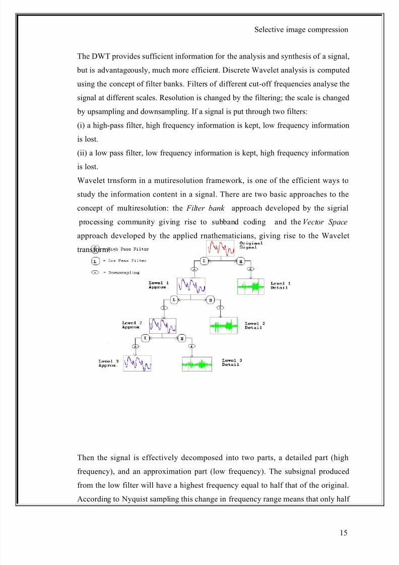
The DWT provides sufficient information for the analysis and synthesis of a signal,
but is advantageously, much more efficient. Discrete Wavelet analysis is computed
using the concept of filter banks. Filters of different cut-off frequencies analyse the
signal at different scales. Resolution is changed by the filtering; the scale is changed by upsampling and downsampling. If a signal is put through two filters:
(i) a high-pass filter, high frequency information is kept, low frequency information
is lost.
(ii) a low pass filter, low frequency information is kept, high frequency information
is lost.
Wavelet trnsform in a mutiresolution framework, is one of the efficient ways to
study the information content in a signal. There are two basic approaches to theconcept of multiresolution: the Filter bank approach developed by the sigrial
processing community giving rise to subband coding and the Vector Space
approach developed by the applied rnathematicians, giving rise to the Wavelet
transform.
Then the signal is effectively decomposed into two parts, a detailed part (high
frequency), and an approximation part (low frequency). The subsignal produced
from the low filter will have a highest frequency equal to half that of the original.
According to Nyquist sampling this change in frequency range means that only half
15
8/8/2019 Image Compression Black Book3
http://slidepdf.com/reader/full/image-compression-black-book3 16/73
Selective image compression
of the original samples need to be kept in order to perfectly reconstruct the signal.
More specifically this means that upsampling can be used to remove every second
sample. The scale has now been doubled. The resolution has also been changed, the
filtering made the frequency resolution better, but reduced the time resolution.
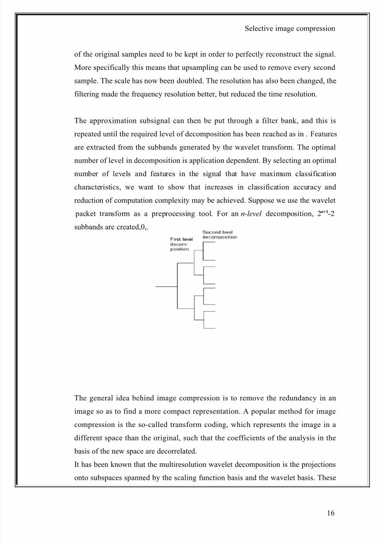
The approximation subsignal can then be put through a filter bank, and this is
repeated until the required level of decomposition has been reached as in . Features
are extracted from the subbands generated by the wavelet transform. The optimal
number of level in decomposition is application dependent. By selecting an optimal
number of levels and features in the signal that have maximum classification
characteristics, we want to show that increases in classification accuracy andreduction of computation complexity may be achieved. Suppose we use the wavelet
packet transform as a preprocessing tool. For an n-level decomposition, 2n+1-2
subbands are created,0,.
The general idea behind image compression is to remove the redundancy in an
image so as to find a more compact representation. A popular method for image
compression is the so-called transform coding, which represents the image in a
different space than the original, such that the coefficients of the analysis in the
basis of the new space are decorrelated.
It has been known that the multiresolution wavelet decomposition is the projections
onto subspaces spanned by the scaling function basis and the wavelet basis. These
16
8/8/2019 Image Compression Black Book3
http://slidepdf.com/reader/full/image-compression-black-book3 17/73
Selective image compression
projections on the scaling functions basis yield approximations of the signal and the
projections on the wavelet basis yield the differences between the approximations of
two adjacent levels of resolution.
Therefore, the wavelet detail images are decorrelated and can be used for image
compression. Indeed, the detail images obtained from the wavelet transform consist
of edges in the image. Since there is little correlation among the values on pixels in
the edge images, it is easily understood why the wavelet transform is useful in
image compression applications. Indeed, image compression is one of the most
popular applications of the wavelet transform as in ,.
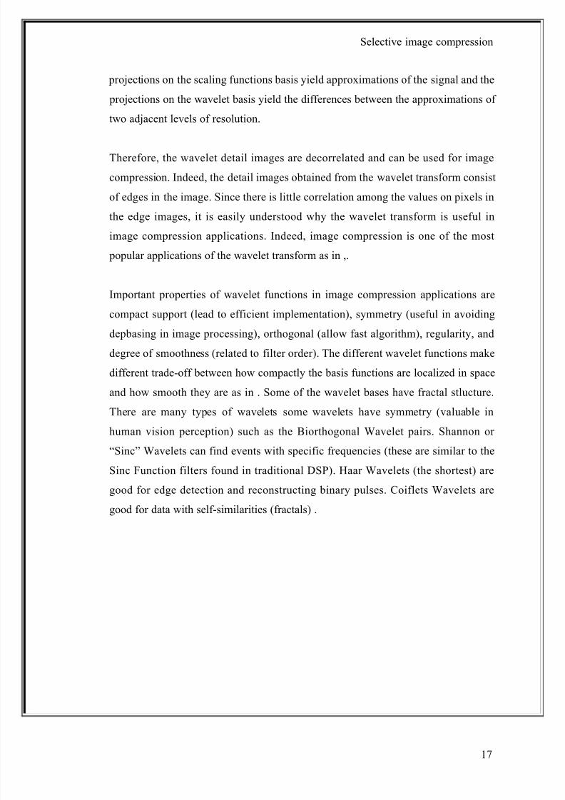
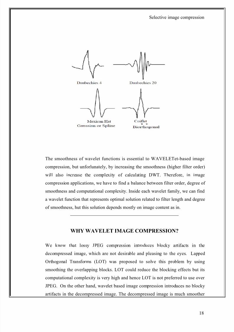
Important properties of wavelet functions in image compression applications are
compact support (lead to efficient implementation), symmetry (useful in avoiding
depbasing in image processing), orthogonal (allow fast algorithm), regularity, and
degree of smoothness (related to filter order). The different wavelet functions make
different trade-off between how compactly the basis functions are localized in space
and how smooth they are as in . Some of the wavelet bases have fractal stlucture.
There are many types of wavelets some wavelets have symmetry (valuable in
human vision perception) such as the Biorthogonal Wavelet pairs. Shannon or
“Sinc” Wavelets can find events with specific frequencies (these are similar to the
Sinc Function filters found in traditional DSP). Haar Wavelets (the shortest) are
good for edge detection and reconstructing binary pulses. Coiflets Wavelets are
good for data with self-similarities (fractals) .
17
8/8/2019 Image Compression Black Book3
http://slidepdf.com/reader/full/image-compression-black-book3 18/73
Selective image compression
The smoothness of wavelet functions is essential to WAVELETet-based image
compression, but unforlunately, by increasing the smoothness (higher filter order)
will also increase the complexity of calculating DWT. Therefore, in image
compression applications, we have to find a balance between filter order, degree of
smoothness and computational complexity. Inside each wavelet family, we can find
a wavelet function that represents optimal solution related to filter length and degree
of smoothness, hut this solution depends mostly on image content as in.
WHY WAVELET IMAGE COMPRESSION?
We know that lossy JPEG compression introduces blocky artifacts in the
decompressed image, which are not desirable and pleasing to the eyes. Lapped
Orthogonal Transforms (LOT) was proposed to solve this problem by using
smoothing the overlapping blocks. LOT could reduce the blocking effects but its
computational complexity is very high and hence LOT is not preferred to use over
JPEG. On the other hand, wavelet based image compression introduces no blocky
artifacts in the decompressed image. The decompressed image is much smoother
18
8/8/2019 Image Compression Black Book3
http://slidepdf.com/reader/full/image-compression-black-book3 19/73
Selective image compression
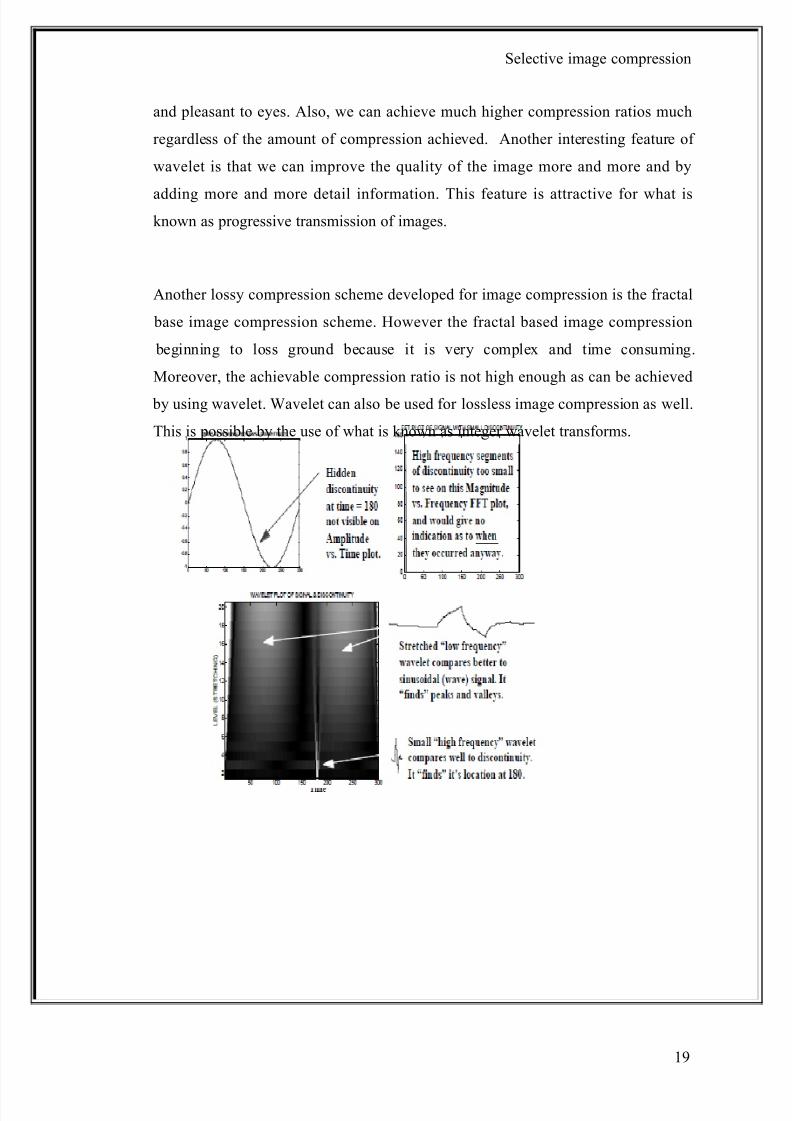
and pleasant to eyes. Also, we can achieve much higher compression ratios much
regardless of the amount of compression achieved. Another interesting feature of
wavelet is that we can improve the quality of the image more and more and by
adding more and more detail information. This feature is attractive for what isknown as progressive transmission of images.
Another lossy compression scheme developed for image compression is the fractal
base image compression scheme. However the fractal based image compression
beginning to loss ground because it is very complex and time consuming.
Moreover, the achievable compression ratio is not high enough as can be achieved
by using wavelet. Wavelet can also be used for lossless image compression as well.
This is possible by the use of what is known as integer wavelet transforms.
19
8/8/2019 Image Compression Black Book3
http://slidepdf.com/reader/full/image-compression-black-book3 20/73
Selective image compression
TIME FREQUENCY PLOT
Wavelet transform provides ‘TIME-FREQUENCY’ representation of a signal, it
uses MULTI-RESOLUTION technique by which different frequencies are analyzed
with different resolutions and it is mostly used to analyze NON-STATIONARY
SIGNALS.
We know that most signals in practice are TIME-DOMAIN signals and when you
plot it you get TIME-AMPLITUDE representation. But for some applications the
actual information is hidden in the frequency content of the signal. To find the
frequency content we use FOURIER TRANSFORM. So, FT gives us
FREQUENCY-AMPLITUDE representation of the time-domain signal.
So, we know that no frequency information is present in time-domain signal and no
time related information is present in frequency-domain signal. But what if we
require both time and frequency information at the same time???
FT tells us how much of each frequency exists in a signal, BUT it does not tell us
when in time these contents exist. Now if the signal is STATIONARY i.e. its
frequency content do not change in time then we do not need to know when these
contents occur because they are present at ALL TIMES!
20
8/8/2019 Image Compression Black Book3
http://slidepdf.com/reader/full/image-compression-black-book3 21/73
Selective image compression
But this is not the case for NON STATIONARY signals i.e. signal whose frequency
response changes with time. e.g. Biomedical signals like ECG, EEG,EMG. .
Here if you are just concerned with what frequency contents are present then youcan use FT but what if you want to simultaneously know ‘When’ these frequency
contents are present. Hence, there is a need for TIME-FREQUENCY representation
of the signal i.e. to get time and frequency information simultaneously.
Need for MULTI-RESOLUTION technique:
So, many transforms were developed for time frequency representation. One of
them was Short time Fourier Transform. In STFT signal is divided into short
segments and stationary condition for non-stationary signal is assumed. Then awindow function equal to the length of the segment is selected. It is multiplied with
the
signal. Then its Fourier transform is taken. The window is then shifted and the
process is repeated. One can say STFT is windowed FT. This gives time-freq
representation of the signal. I wont go into detail it will take lot of time. So, what
was the problem with STFT...RESOLUTION!!!
STFT analyses signals using windows of finite length, which covers only a portion
of the signal. So you just know “a band of frequency” that exist in a signal not the
exact frequency components that exists in the signal. So frequency resolution is
poor. Narrower this window, poorer frequency resolution but if the window is
shorter you will be able to resolve your signal better in time i.e. good time
resolution. Conversely, wider the window, good freq resolution but poor time
resolution.
To solve this resolution problem wavelet transform :
The wavelet analysis is done similar to the STFT analysis. The signal to be analyzed
is multiplied with a wavelet function just as it is multiplied with a window function
in STFT, and then the transform is computed for each segment generated. But here
the width of the window is changed for each single frequency component. This is
called MULTI-RESOLUTION analysis i.e. it analyses the signals at different freq
21
8/8/2019 Image Compression Black Book3
http://slidepdf.com/reader/full/image-compression-black-book3 22/73
Selective image compression
with different resolution.
The Wavelet Transform, at high frequencies, gives good time resolution and poor
frequency resolution, while at low frequencies; the Wavelet Transform gives good
frequency resolution and poor time resolution
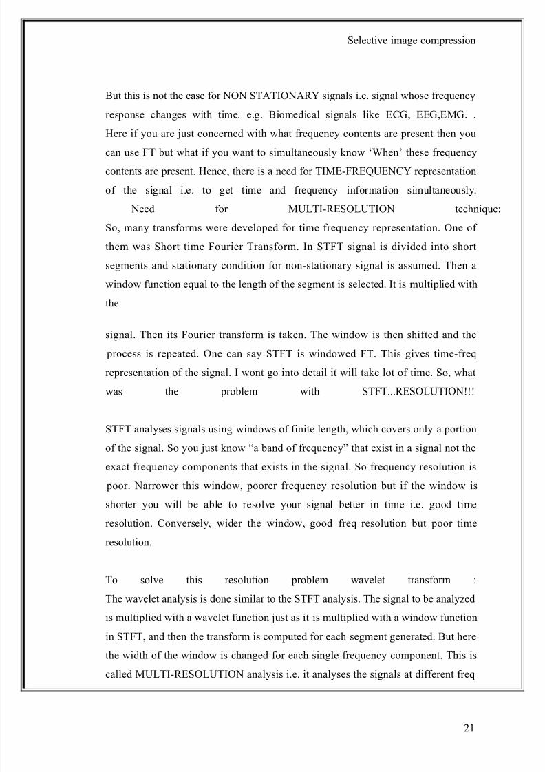
Wavelet Time/Frequency Analysis:The power of the wavelet transform is that it
allows signal variation through time to be examined. Frequently the first example
used for wavelet packet time/frequency analysis is the so called linear chirp, which
exponentially increases in frequency over time. Rather than jumping into the linear
chirp, let us first look at a simple sine function. Figure (1) shows the function
sin(4 Pix), in the range {0..8 Pi}, sampled at 1024 evenly spaced points.
Figure (1)
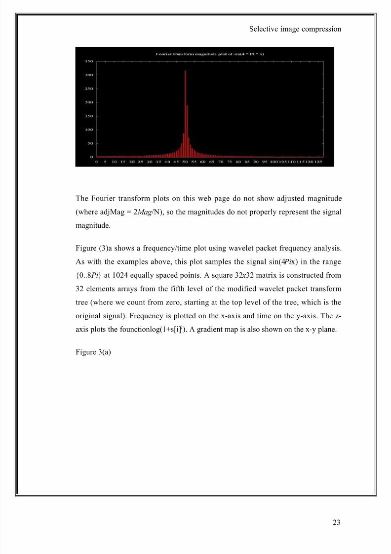
A magnitude plot of the result of a Fourier transform of the sampled signal is shown
in Figure (2).(here only the relevant part of the plot is shown). This shows a signal
of about 51 cycles, which is what I get when I count the cycles by hand.
Figure (2)
22
8/8/2019 Image Compression Black Book3
http://slidepdf.com/reader/full/image-compression-black-book3 23/73
Selective image compression
The Fourier transform plots on this web page do not show adjusted magnitude
(where adjMag = 2Mag /N), so the magnitudes do not properly represent the signal
magnitude.
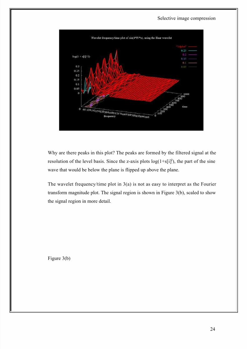
Figure (3)a shows a frequency/time plot using wavelet packet frequency analysis.
As with the examples above, this plot samples the signal sin(4 Pix) in the range
{0..8 Pi} at 1024 equally spaced points. A square 32 x32 matrix is constructed from
32 elements arrays from the fifth level of the modified wavelet packet transformtree (where we count from zero, starting at the top level of the tree, which is the
original signal). Frequency is plotted on the x-axis and time on the y-axis. The z-
axis plots the founctionlog(1+s[i]2). A gradient map is also shown on the x-y plane.
Figure 3(a)
23
8/8/2019 Image Compression Black Book3
http://slidepdf.com/reader/full/image-compression-black-book3 24/73
Selective image compression
Why are there peaks in this plot? The peaks are formed by the filtered signal at the
resolution of the level basis. Since the z-axis plots log(1+s[i] 2), the part of the sine
wave that would be below the plane is flipped up above the plane.
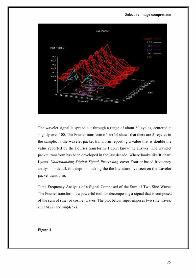
The wavelet frequency/time plot in 3(a) is not as easy to interpret as the Fourier
transform magnitude plot. The signal region is shown in Figure 3(b), scaled to show
the signal region in more detail.
Figure 3(b)
24
8/8/2019 Image Compression Black Book3
http://slidepdf.com/reader/full/image-compression-black-book3 25/73
Selective image compression
The wavelet signal is spread out through a range of about 80 cycles, centered at
slightly over 100. The Fourier transform of sin(4 x) shows that there are 51 cycles in
the sample. Is the wavelet packet transform reporting a value that is double the
value reported by the Fourier transform? I don't know the answer. The wavelet
packet transform has been developed in the last decade. Where books like Richard
Lyons' Understanding Digital Signal Processing cover Fourier based frequency
analysis in detail, this depth is lacking the the literature I've seen on the wavelet
packet transform.
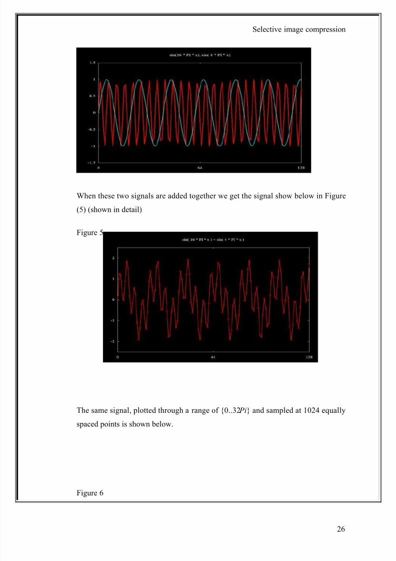
Time Frequency Analysis of a Signal Composed of the Sum of Two Sine Waves
The Fourier transform is a powerful tool for decomposing a signal that is composedof the sum of sine (or cosine) waves. The plot below super imposes two sine waves,
sin(16 Pix) and sin(4 Pix).
Figure 4
25
8/8/2019 Image Compression Black Book3
http://slidepdf.com/reader/full/image-compression-black-book3 26/73
Selective image compression
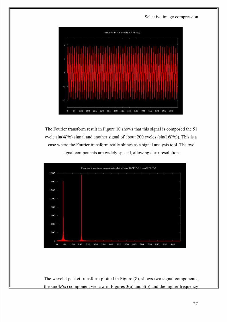
When these two signals are added together we get the signal show below in Figure
(5) (shown in detail)
Figure 5
The same signal, plotted through a range of {0..32 Pi} and sampled at 1024 equally
spaced points is shown below.
Figure 6
26
8/8/2019 Image Compression Black Book3
http://slidepdf.com/reader/full/image-compression-black-book3 27/73
Selective image compression
The Fourier transform result in Figure 10 shows that this signal is composed the 51
cycle sin(4 Pix) signal and another signal of about 200 cycles (sin(16 Pix)). This is a
case where the Fourier transform really shines as a signal analysis tool. The two
signal components are widely spaced, allowing clear resolution.
Figure 7
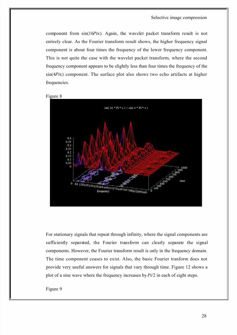
The wavelet packet transform plotted in Figure (8). shows two signal components,
the sin(4 Pix) component we saw in Figures 3(a) and 3(b) and the higher frequency
27
8/8/2019 Image Compression Black Book3
http://slidepdf.com/reader/full/image-compression-black-book3 28/73
Selective image compression
component from sin(16 Pix). Again, the wavelet packet transform result is not
entirely clear. As the Fourier transform result shows, the higher frequency signal
component is about four times the frequency of the lower frequency component.
This is not quite the case with the wavelet packet transform, where the secondfrequency component appears to be slightly less than four times the frequency of the
sin(4 Pix) component. The surface plot also shows two echo artifacts at higher
frequencies.
Figure 8
For stationary signals that repeat through infinity, where the signal components are
sufficiently separated, the Fourier transform can clearly separate the signal
components. However, the Fourier transform result is only in the frequency domain.
The time component ceases to exist. Also, the basic Fourier tranform does not
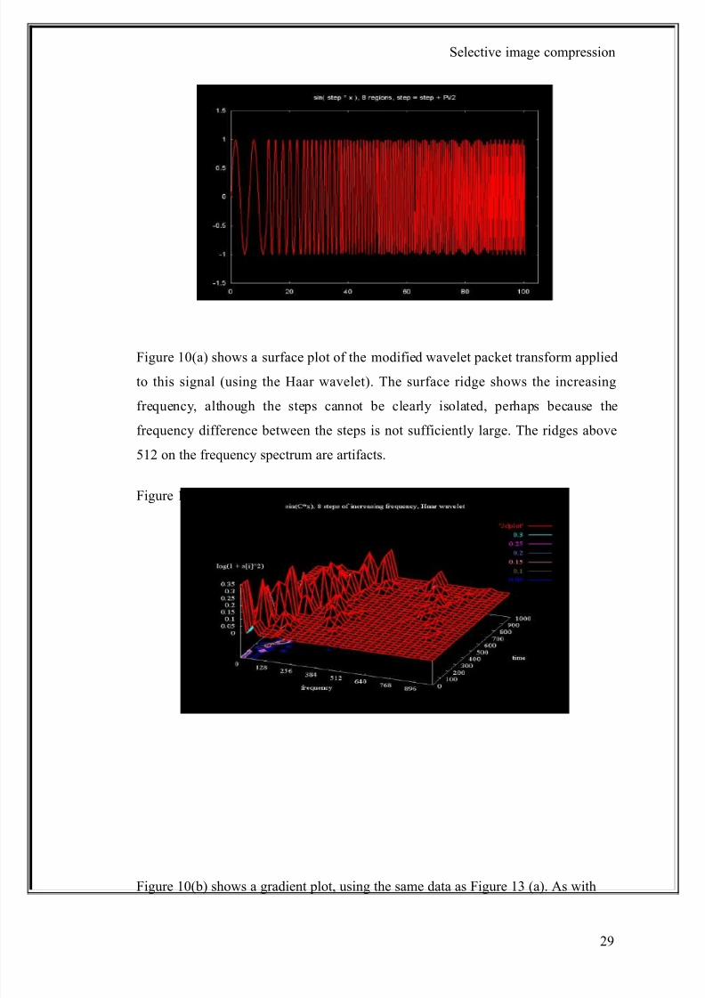
provide very useful answers for signals that vary through time. Figure 12 shows a
plot of a sine wave where the frequency increases by Pi/2 in each of eight steps.
Figure 9
28
8/8/2019 Image Compression Black Book3
http://slidepdf.com/reader/full/image-compression-black-book3 29/73
Selective image compression
Figure 10(a) shows a surface plot of the modified wavelet packet transform applied
to this signal (using the Haar wavelet). The surface ridge shows the increasing
frequency, although the steps cannot be clearly isolated, perhaps because the
frequency difference between the steps is not sufficiently large. The ridges above
512 on the frequency spectrum are artifacts.
Figure 10 (a)
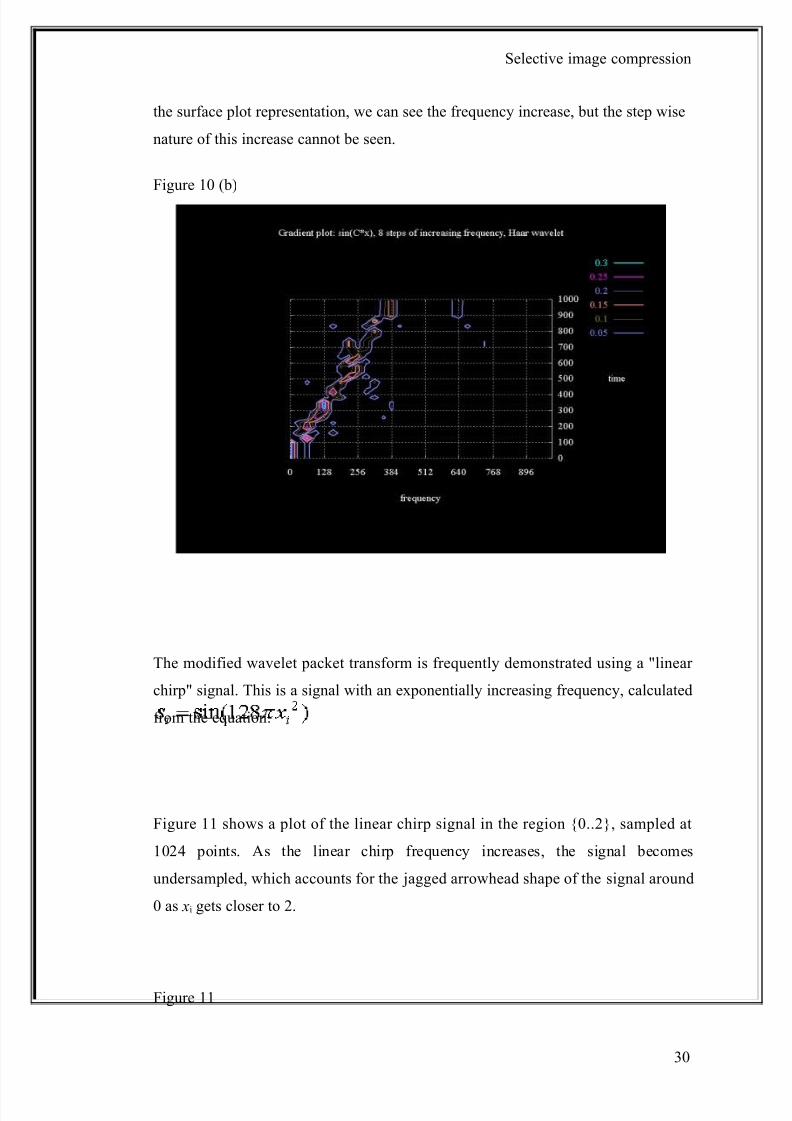
Figure 10(b) shows a gradient plot, using the same data as Figure 13 (a). As with
29
8/8/2019 Image Compression Black Book3
http://slidepdf.com/reader/full/image-compression-black-book3 30/73
Selective image compression
the surface plot representation, we can see the frequency increase, but the step wise
nature of this increase cannot be seen.
Figure 10 (b)
The modified wavelet packet transform is frequently demonstrated using a "linear
chirp" signal. This is a signal with an exponentially increasing frequency, calculated
from the equation:
Figure 11 shows a plot of the linear chirp signal in the region {0..2}, sampled at
1024 points. As the linear chirp frequency increases, the signal becomes
undersampled, which accounts for the jagged arrowhead shape of the signal around
0 as xi gets closer to 2.
Figure 11
30

8/8/2019 Image Compression Black Book3
http://slidepdf.com/reader/full/image-compression-black-book3 31/73
Selective image compression
Figure (12) shows the result of the modified wavelet packet transform, using the
Haar wavelet, applied to the linear chirp. The peaks exist because the signal is
sampled at a particular resolution and the absolute value of the signal is plotted.
Note that as the frequency increases the peaks seem to disappear as the signal
cycles get close together. The ridge along the diagonal shows that the signal
frequency increases through time. In theory the linear chirp frequency increases
exponentially, not linearly as this plot suggests. However, the signal is sampled at a
finite number of points, so the exponential nature of the signal disappears as the
signal becomes under sampled. The ridges that are perpendicular to the main
diagonal line are artifacts.
Figure 12
31
8/8/2019 Image Compression Black Book3
http://slidepdf.com/reader/full/image-compression-black-book3 32/73
Selective image compression
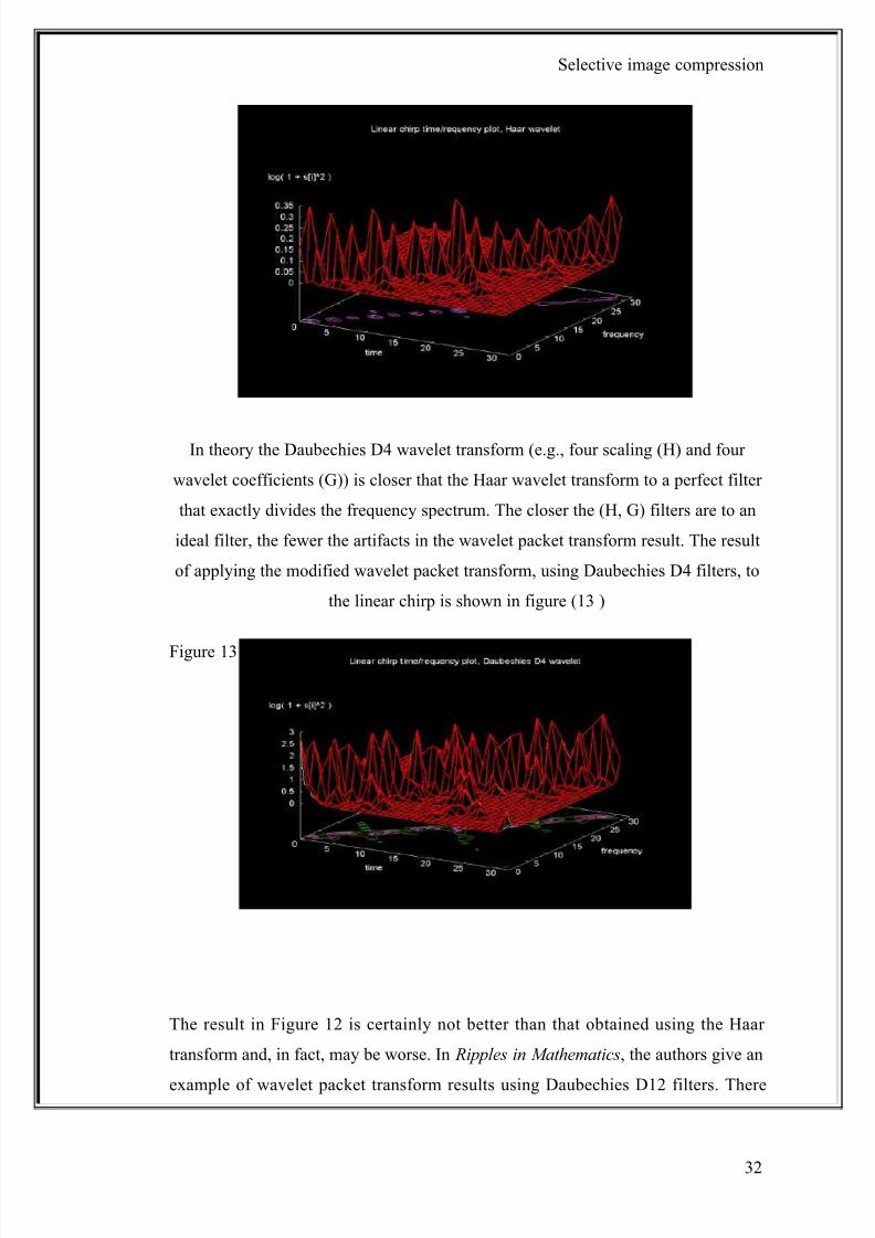
In theory the Daubechies D4 wavelet transform (e.g., four scaling (H) and four
wavelet coefficients (G)) is closer that the Haar wavelet transform to a perfect filter
that exactly divides the frequency spectrum. The closer the (H, G) filters are to an
ideal filter, the fewer the artifacts in the wavelet packet transform result. The result
of applying the modified wavelet packet transform, using Daubechies D4 filters, to
the linear chirp is shown in figure (13 )
Figure 13
The result in Figure 12 is certainly not better than that obtained using the Haar
transform and, in fact, may be worse. In Ripples in Mathematics, the authors give an
example of wavelet packet transform results using Daubechies D12 filters. There
32
8/8/2019 Image Compression Black Book3
http://slidepdf.com/reader/full/image-compression-black-book3 33/73
Selective image compression
are notable fewer artifacts in this case. Jensen and la Cour-Harbo mention that as
the filter length approaches the signal size, the filter approaches an ideal filter.
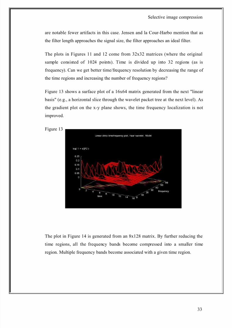
The plots in Figures 11 and 12 come from 32x32 matrices (where the original
sample consisted of 1024 points). Time is divided up into 32 regions (as is
frequency). Can we get better time/frequency resolution by decreasing the range of
the time regions and increasing the number of frequency regions?
Figure 13 shows a surface plot of a 16x64 matrix generated from the next "linear
basis" (e.g., a horizontal slice through the wavelet packet tree at the next level). As
the gradient plot on the x-y plane shows, the time frequency localization is not
improved.
Figure 13
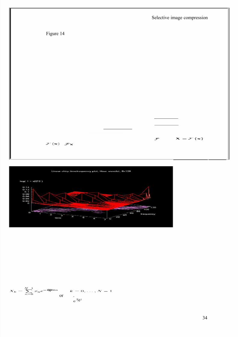
The plot in Figure 14 is generated from an 8x128 matrix. By further reducing the
time regions, all the frequency bands become compressed into a smaller time
region. Multiple frequency bands become associated with a given time region.
33
8/8/2019 Image Compression Black Book3
http://slidepdf.com/reader/full/image-compression-black-book3 34/73
Selective image compression
Figure 14
Discrete Fourier transform:The sequence of N complex numbers x0, ..., x N −1 is
transformed into the sequence of N complex numbers X 0, ..., X N −1 by the DFT
according to the formula:
where i is the imaginary unit and is a primitive N'th root of unity.
(This expression can also be written in terms of a DFT matrix; when scaled
appropriately it becomes a unitary matrix and the X k can thus be viewed as
coefficients of x in an orthonormal basis.)
The transform is sometimes denoted by the symbol , as in or
or .
34
8/8/2019 Image Compression Black Book3
http://slidepdf.com/reader/full/image-compression-black-book3 35/73
Selective image compression
The inverse discrete Fourier transform (IDFT) is given by
A simple description of these equations is that the complex numbers X k represent
the amplitude and phase of the different sinusoidal components of the input "signal"
xn. The DFT computes the X k from the xn, while the IDFT shows how to compute
the xn as a sum of sinusoidal components with frequency k / N
cycles per sample. By writing the equations in this form, we are making extensive
use of Euler's formula to express sinusoids in terms of complex exponentials, which
are much easier to manipulate. In the same way, by writing X k in polar form, we
obtain the sinusoid amplitude Ak / N and phase φk from the complex modulus and
argument of X k , respectively:
Note that the normalization factor multiplying the DFT and IDFT (here 1 and 1/ N )
and the signs of the exponents are merely conventions, and differ in some
treatments. The only requirements of these conventions are that the DFT and IDFT
have opposite-sign exponents and that the product of their normalization factors be
1/ N . A normalization of for both the DFT and IDFT makes the transforms
unitary, which has some theoretical advantages, but it is often more practical in
numerical computation to perform the scaling all at once as above (and a unit
scaling can be convenient in other ways).
(The convention of a negative sign in the exponent is often convenient because it
means that X k is the amplitude of a "positive frequency" 2πk / N . Equivalently, the
DFT is often thought of as a matched filter : when looking for a frequency of +1, one
correlates the incoming signal with a frequency of −1.)
35
8/8/2019 Image Compression Black Book3
http://slidepdf.com/reader/full/image-compression-black-book3 36/73
Selective image compression
Wavelet:A wavelet is a wave-like oscillation with an amplitude that starts out at
zero, increases, and then decreases back to zero. It can typically be visualized as a
"brief oscillation" like one might see recorded by a seismograph or heart monitor.
Generally, wavelets are purposefully crafted to have specific properties that makethem useful for signal processing. Wavelets can be combined, using a "shift,
multiply and sum" technique called convolution, with portions of an unknown
signal to extract information from the unknown signal.
The word wavelet is due to Morlet and Grossmann in the early 1980s. They used
the French word ondelette, meaning "small wave". Soon it was transferred to
English by translating "onde" into "wave", giving "wavelet".
For example, a wavelet could be created to have a frequency of Middle ‘C’ and a
short duration of roughly a 32nd note. If this wavelet were to be convolved at
periodic intervals with a signal created from the recording of a song, then the results
of these convolutions would be useful for determining when the Middle C note was
being played in the song. Mathematically, the wavelet will resonate if the unknown
signal contains information of similar frequency - just as a tuning fork physically
resonates with sound waves of its specific tuning frequency. This concept of resonance is at the core of many practical applications of wavelet theory.
As wavelets are a mathematical tool they can be used to extract information from
many different kinds of data, including - but certainly not limited to - audio signals
and images. Sets of wavelets are generally needed to analyze data fully. A set of
"complementary" wavelets will deconstruct data without gaps or overlap so that the
deconstruction process is mathematically reversible. Thus, sets of complementary
wavelets are useful in wavelet based compression/decompression algorithms where
it is desirable to recover the original information with minimal loss.
More technically, a wavelet is a mathematical function used to divide a given
function or continuous-time signal into different scale components. Usually one can
assign a frequency range to each scale component. Each scale component can then
be studied with a resolution that matches its scale. A wavelet transform is the
representation of a function by wavelets. The wavelets are scaled and translated
36
8/8/2019 Image Compression Black Book3
http://slidepdf.com/reader/full/image-compression-black-book3 37/73
Selective image compression
copies (known as "daughter wavelets") of a finite-length or fast-decaying oscillating
waveform (known as the "mother wavelet").
In formal terms, this representation is a wavelet series representation of a square-
integrable function with respect to either a complete, orthonormal set of basis
functions, or an over complete set or Frame of a vector space, for the Hilbert space
of square integrable functions.
Wavelet classification: Wavelet transforms are classified into discrete wavelet
transforms (DWTs) and continuous wavelet transforms (CWTs). Note that both
DWT and CWT are continuous-time (analog) transforms. They can be used to
represent continuous-time (analog) signals. CWTs operate over every possible scale
and translation whereas DWTs use a specific subset of scale and translation values
or representation grid.
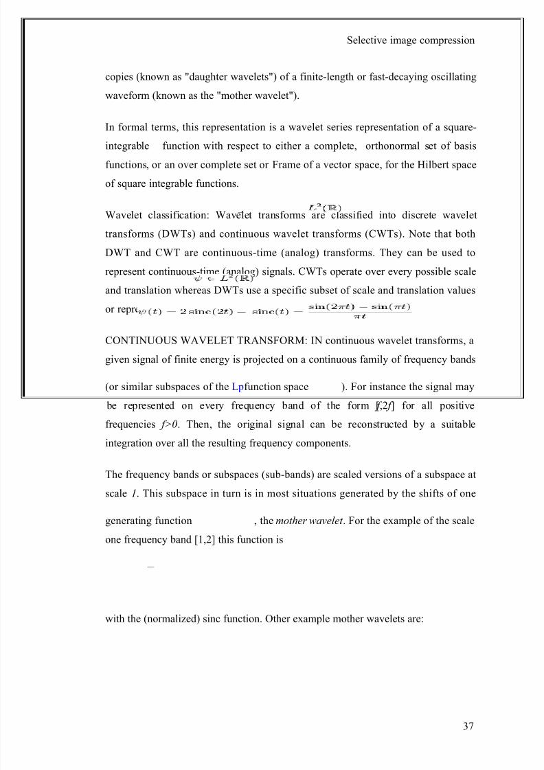
CONTINUOUS WAVELET TRANSFORM: IN continuous wavelet transforms, a
given signal of finite energy is projected on a continuous family of frequency bands
(or similar subspaces of the L pfunction space ). For instance the signal may
be represented on every frequency band of the form [ f ,2 f ] for all positive
frequencies f>0. Then, the original signal can be reconstructed by a suitable
integration over all the resulting frequency components.
The frequency bands or subspaces (sub-bands) are scaled versions of a subspace at
scale 1. This subspace in turn is in most situations generated by the shifts of one
generating function , the mother wavelet . For the example of the scale
one frequency band [1,2] this function is
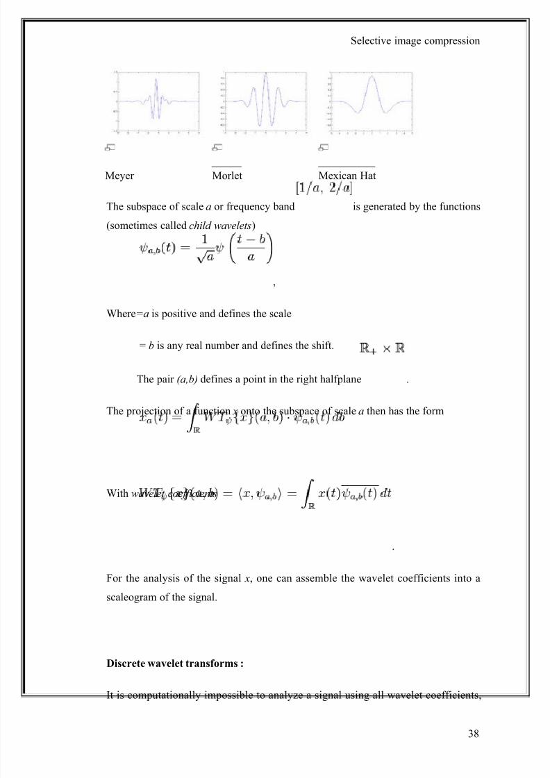
with the (normalized) sinc function. Other example mother wavelets are:
37
8/8/2019 Image Compression Black Book3
http://slidepdf.com/reader/full/image-compression-black-book3 38/73
Selective image compression
Meyer Morlet Mexican Hat
The subspace of scale a or frequency band is generated by the functions
(sometimes called child wavelets)
,
Where=a is positive and defines the scale
= b is any real number and defines the shift.
The pair (a,b) defines a point in the right halfplane .
The projection of a function x onto the subspace of scale a then has the form
With wavelet coefficients
.
For the analysis of the signal x, one can assemble the wavelet coefficients into a
scaleogram of the signal.
Discrete wavelet transforms :
It is computationally impossible to analyze a signal using all wavelet coefficients,
38
8/8/2019 Image Compression Black Book3
http://slidepdf.com/reader/full/image-compression-black-book3 39/73
Selective image compression
so one may wonder if it is sufficient to pick a discrete subset of the upper half plane
to be able to reconstruct a signal from the corresponding wavelet coefficients. One
such system is the affine system for some real parameters a>1, b>0. The
corresponding discrete subset of the half plane consists of all the points
with integers . The corresponding baby wavelets are now
given as
ψm,n(t ) = a− m / 2ψ(a− mt − nb).
A sufficient condition for the reconstruction of any signal x of finite energy by the
formula
is that the functions form a tight frame of .
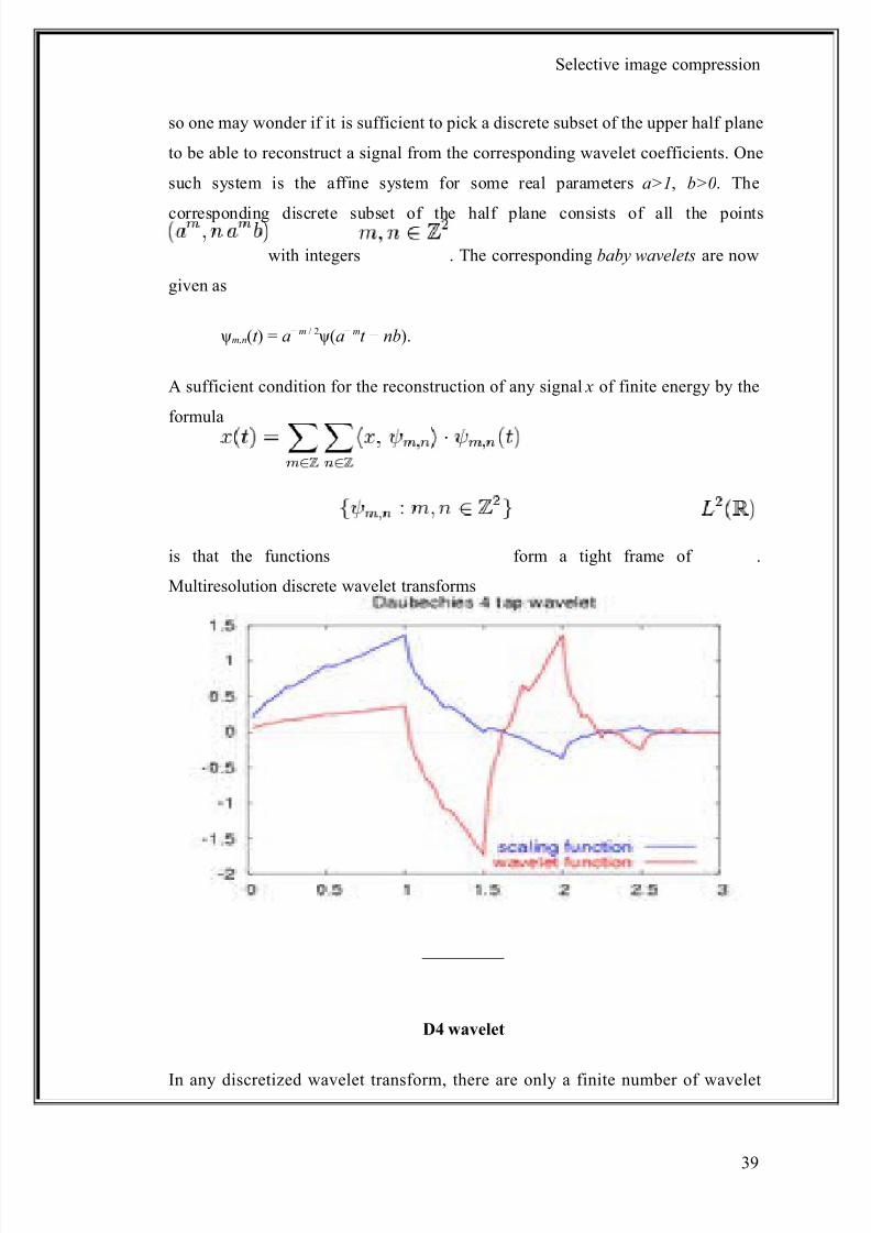
Multiresolution discrete wavelet transforms
D4 wavelet
In any discretized wavelet transform, there are only a finite number of wavelet
39
8/8/2019 Image Compression Black Book3
http://slidepdf.com/reader/full/image-compression-black-book3 40/73
Selective image compression
coefficients for each bounded rectangular region in the upper half plane. Still, each
coefficient requires the evaluation of an integral. To avoid this numerical
complexity, one needs one auxiliary function, the father wavelet .
Further, one has to restrict a to be an integer. A typical choice is a=2 and b=1. The
most famous pair of father and mother wavelets is the Daubechies 4 tap wavelet.
From the mother and father wavelets one constructs the subspaces
, where φm,n(t ) = 2 − m / 2φ(2 − mt − n)
and
, where ψm,n(t ) = 2 − m / 2ψ(2 − mt − n).
From these one requires that the sequence
forms a multiresolution analysis of and that the subspacesare the orthogonal "differences" of the above
sequence, that is, W m is the orthogonal complement of V m inside the subspace V m − 1.
In analogy to the sampling theorem one may conclude that the space V m with
sampling distance 2m more or less covers the frequency baseband from 0 to 2 − m − 1.
As orthogonal complement, W m roughly covers the band [2 − m − 1,2− m].
From those inclusions and orthogonality relations follows the existence of
sequences and that satisfy the identities
and
and
and .
40
8/8/2019 Image Compression Black Book3
http://slidepdf.com/reader/full/image-compression-black-book3 41/73
Selective image compression
The second identity of the first pair is a refinement equation for the father wavelet
φ. Both pairs of identities form the basis for the algorithm of the fast wavelet
transform.
Mother wavelet: For practical applications, and for efficiency reasons, one prefers
continuously differentiable functions with compact support as mother (prototype)
wavelet (functions). However, to satisfy analytical requirements (in the continuous
WT) and in general for theoretical reasons, one chooses the wavelet functions from
a subspace of the space
This is the space of measurable functions that are absolutely and square integrable:
and
Being in this space ensures that one can formulate the conditions of zero mean and
square norm one:
is the condition for zero mean, and
is the condition for square norm one.
For ψ to be a wavelet for the continuous wavelet transform (see there for exact
statement), the mother wavelet must satisfy an admissibility criterion (loosely
speaking, a kind of half-differentiability) in order to get a stably invertible
transform.
For the discrete wavelet transform, one needs at least the condition that the wavelet
series is a representation of the identity in the space . Most constructions of
discrete WT make use of the multiresolution analysis, which defines the wavelet by
a scaling function. This scaling function itself is solution to a functional equation.
In most situations it is useful to restrict ψ to be a continuous function with a higher
41
8/8/2019 Image Compression Black Book3
http://slidepdf.com/reader/full/image-compression-black-book3 42/73
Selective image compression
number M of vanishing moments, i.e. for all integer m<M
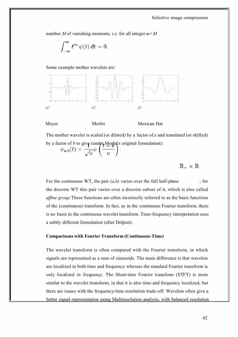
Some example mother wavelets are:
Meyer Morlet Mexican Hat
The mother wavelet is scaled (or dilated) by a factor of a and translated (or shifted)
by a factor of b to give (under Morlet's original formulation):
For the continuous WT, the pair (a,b) varies over the full half-plane ; for
the discrete WT this pair varies over a discrete subset of it, which is also called
affine group.These functions are often incorrectly referred to as the basis functions
of the (continuous) transform. In fact, as in the continuous Fourier transform, there
is no basis in the continuous wavelet transform. Time-frequency interpretation uses
a subtly different formulation (after Delprat).
Comparisons with Fourier Transform (Continuous-Time)
The wavelet transform is often compared with the Fourier transform, in which
signals are represented as a sum of sinusoids. The main difference is that wavelets
are localized in both time and frequency whereas the standard Fourier transform is
only localized in frequency. The Short-time Fourier transform (STFT) is more
similar to the wavelet transform, in that it is also time and frequency localized, but
there are issues with the frequency/time resolution trade-off. Wavelets often give a
better signal representation using Multiresolution analysis, with balanced resolution
42
8/8/2019 Image Compression Black Book3
http://slidepdf.com/reader/full/image-compression-black-book3 43/73
Selective image compression
at any time and frequency.
The discrete wavelet transform is also less computationally complex, taking O( N )
time as compared to O( N log N ) for the fast Fourier transform. This computational
advantage is not inherent to the transform, but reflects the choice of a logarithmic
division of frequency, in contrast to the equally spaced frequency divisions of the
FFT.It is also important to note that this complexity only applies when the filter size
has no relation to the signal size. A wavelet without compact support such as the
Shannon wavelet would require O( N^2). (For instance, a logarithmic Fourier
Transform also exists with O( N ) complexity, but the original signal must be
sampled logarithmically in time, which is only useful for certain types of signals .
Scaling filter:
An orthogonal wavelet is entirely defined by the scaling filter - a low-pass finite
impulse response (FIR) filter of length 2N and sum 1. In biorthogonal wavelets,
separate decomposition and reconstruction filters are defined.
For analysis with orthogonal wavelets the high pass filter is calculated as the
quadrature mirror filter of the low pass, and reconstruction filters are the time
reverse of the decomposition filters.
Daubechies and Symlet wavelets can be defined by the scaling filter.
Scaling function: Wavelets are defined by the wavelet function ψ(t ) (i.e. the
mother wavelet) and scaling function φ(t ) (also called father wavelet) in the time
domain.
The wavelet function is in effect a band-pass filter and scaling it for each level
halves its bandwidth. This creates the problem that in order to cover the entire
spectrum, an infinite number of levels would be required. The scaling function
filters the lowest level of the transform and ensures all the spectrum is covered.
For a wavelet with compact support, φ(t ) can be considered finite in length and is
43
8/8/2019 Image Compression Black Book3
http://slidepdf.com/reader/full/image-compression-black-book3 44/73
Selective image compression
equivalent to the scaling filter.
44
8/8/2019 Image Compression Black Book3
http://slidepdf.com/reader/full/image-compression-black-book3 45/73
Selective image compression
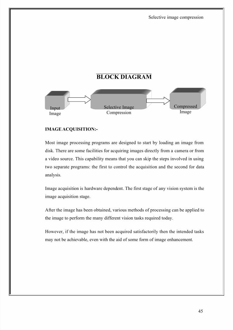
BLOCK DIAGRAM
IMAGE ACQUISITION:-
Most image processing programs are designed to start by loading an image from
disk. There are some facilities for acquiring images directly from a camera or from
a video source. This capability means that you can skip the steps involved in using
two separate programs: the first to control the acquisition and the second for data
analysis.
Image acquisition is hardware dependent. The first stage of any vision system is the
image acquisition stage.
After the image has been obtained, various methods of processing can be applied to
the image to perform the many different vision tasks required today.
However, if the image has not been acquired satisfactorily then the intended tasks
may not be achievable, even with the aid of some form of image enhancement.
CompressedImage
Input
Image
Selective ImageCompression
45
8/8/2019 Image Compression Black Book3
http://slidepdf.com/reader/full/image-compression-black-book3 46/73
Selective image compression
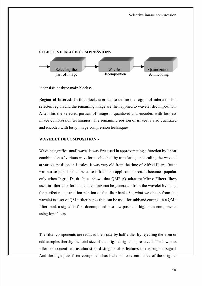
SELECTIVE IMAGE COMPRESSION:-
It consists of three main blocks:-
Region of Interest:-In this block, user has to define the region of interest. Thisselected region and the remaining image are then applied to wavelet decomposition.
After this the selected portion of image is quantized and encoded with lossless
image compression techniques. The remaining portion of image is also quantized
and encoded with lossy image compression techniques.
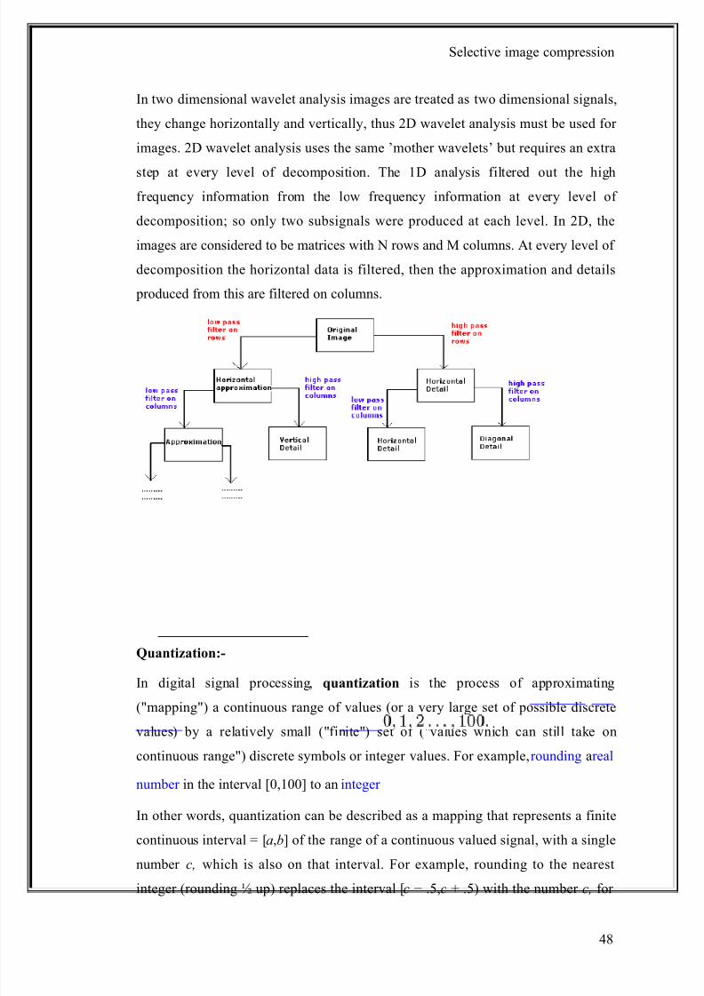
WAVELET DECOMPOSITION:-
Wavelet signifies small wave. It was first used in approximating a function by linear
combination of various waveforms obtained by translating and scaling the wavelet
at various position and scales. It was very old from the time of Alfred Haars. But it
was not so popular then because it found no application area. It becomes popular
only when Ingrid Daubechies shows that QMF (Quadrature Mirror Filter) filters
used in filterbank for subband coding can be generated from the wavelet by using
the perfect reconstruction relation of the filter bank. So, what we obtain from the
wavelet is a set of QMF filter banks that can be used for subband coding. In a QMFfilter bank a signal is first decomposed into low pass and high pass components
using low filters.
The filter components are reduced their size by half either by rejecting the even or
odd samples thereby the total size of the original signal is preserved. The low pass
filter component retains almost all distinguishable features of the original signal.And the high pass filter component has little or no resemblance of the original
WaveletDecomposition
Quantization& Encoding
Selecting the part of Image
46

8/8/2019 Image Compression Black Book3
http://slidepdf.com/reader/full/image-compression-black-book3 47/73
Selective image compression
signal. The low pass component is again decomposed into two components. The
decomposition process can be continued up to the last possible level or up to a
certain desired level. As the high pass filter components have less information
discernible to the original signal, we can eliminate the information contents of thehigh pass filters partially or significantly at each level of decomposition during the
reconstruction process. It is this possibility of elimination of the information
contents of the high pass filter components that gives higher compression ratio in
the case of wavelet based image compression. Simple decomposition and
reconstruction by eliminating less informative parts of the high pass filter
components may not always lead to the compression.
For we have to use certain coding scheme to get higher compression ratios. Some of
the most cited coding algorithms for wavelet based image compression are EZW
(Embedded Zerotree Wavelet) , SPIHT (Set Partitioning in Hierarchical Tree) and
EBCOT (Embedded Block Coding with Optimal Truncation) . EZW is no longer
popular as it has been improved to SPIHT. Now SPIHT and EBCOT are the two
main contenders for wavelet based image coding. JPEG group has accepted
EBCOT as their wavelet based coding scheme to upgrade their JPEG to JPEG2000
version to achieve higher compression ratio and less distortion in the decompressed
signal. So, now the main contender is between SPIHT and JPEG2000.
In any wavelet based image compression scheme, the achievable compression ratio
is not only dependent on the efficiency of the coding scheme, it is also dependent on
the choice of appropriate wavelet filters. Different filters give different compression
ratios for the same image and coding scheme . There are numerous wavelet filters.
It is our task to choice appropriate filters for our compression scheme. For
JPEG2000, filters used 9/7 biothogonal wavelet filters for lossy image compression
and 5/3 for lossless image compression. For SPIHT coding scheme, usually 9/7
biorthogonal filters is used for lossy image compression and S+P transform filters
for lossless image compression. However, 9/7 is not the optimal filters for lossy
image compression, still lot of research is going on about the finding of optimal
filters for lossy image compression for different image types.
47
8/8/2019 Image Compression Black Book3
http://slidepdf.com/reader/full/image-compression-black-book3 48/73
8/8/2019 Image Compression Black Book3
http://slidepdf.com/reader/full/image-compression-black-book3 49/73
Selective image compression
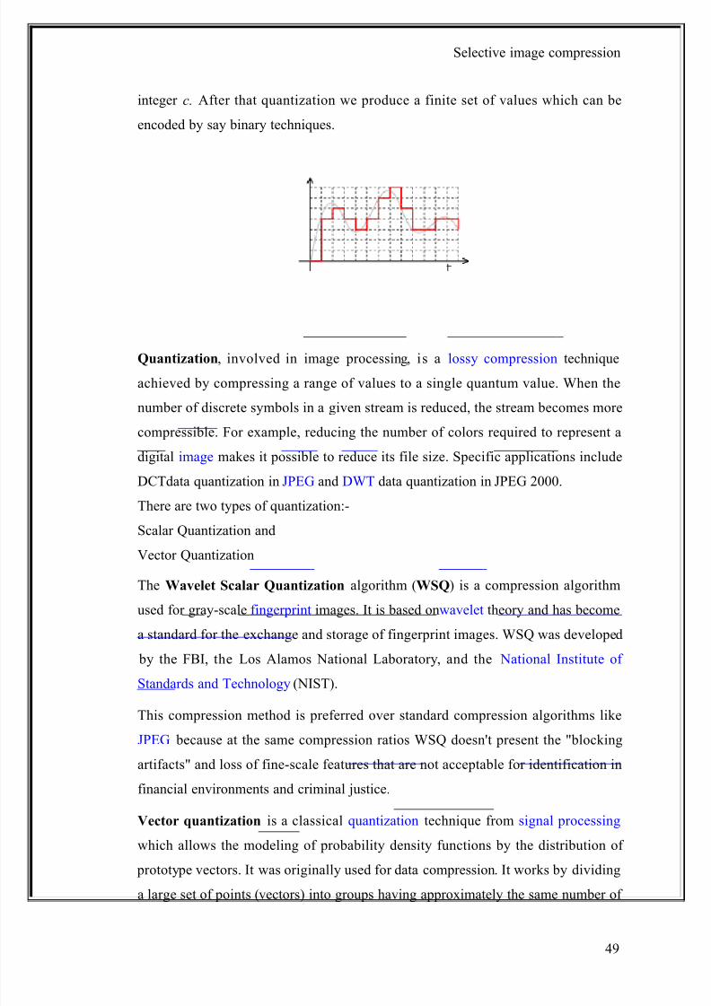
integer c. After that quantization we produce a finite set of values which can be
encoded by say binary techniques.
Quantization, involved in image processing, is a lossy compression technique
achieved by compressing a range of values to a single quantum value. When the
number of discrete symbols in a given stream is reduced, the stream becomes more
compressible. For example, reducing the number of colors required to represent a
digital image makes it possible to reduce its file size. Specific applications include
DCTdata quantization in JPEG and DWT data quantization in JPEG 2000.
There are two types of quantization:-
Scalar Quantization and
Vector Quantization
The Wavelet Scalar Quantization algorithm (WSQ) is a compression algorithm
used for gray-scale fingerprint images. It is based onwavelet theory and has become
a standard for the exchange and storage of fingerprint images. WSQ was developed
by the FBI, the Los Alamos National Laboratory, and the National Institute of
Standards and Technology (NIST).
This compression method is preferred over standard compression algorithms like
JPEG because at the same compression ratios WSQ doesn't present the "blocking
artifacts" and loss of fine-scale features that are not acceptable for identification in
financial environments and criminal justice.
Vector quantization is a classical quantization technique from signal processing
which allows the modeling of probability density functions by the distribution of
prototype vectors. It was originally used for data compression. It works by dividing
a large set of points (vectors) into groups having approximately the same number of
49
8/8/2019 Image Compression Black Book3
http://slidepdf.com/reader/full/image-compression-black-book3 50/73
Selective image compression
points closest to them. Each group is represented by its centroid point, as ink-means
and some other clustering algorithms.
The density matching property of vector quantization is powerful, especially for
identifying the density of large and high-dimensioned data. Since data points are
represented by the index of their closest centroid, commonly occurring data have
low error, and rare data high error. This is why VQ is suitable for lossy data
compression. It can also be used for lossy data correction and density estimation.
Vector quantization is based on the competitive learning paradigm, so it is closely
related to the self-organizing map model.
LOSSLESS ENCODING :-
The existing systems used for lossless encoding are:-
Run length encoding:-
Run-length encoding (RLE) is a very simple form of data compression in
which runs of data (that is, sequences in which the same data value occurs in many
consecutive data elements) are stored as a single data value and count, rather than as
the original run. This is most useful on data that contains many such runs: for example, relatively simple graphic images such as icons, line drawings, and
animations. It is not recommended for use with files that don't have many runs as it
could potentially double the file size.
Simple implementation of each RLE algorithm
Compression efficiency restricted to a particular type of contents
Mainly utilized for encoding of monochrome graphic data
May cause data explosion i.e. the output may be larger than the input or
original.
Huffman coding:-
Huffman coding is an entropy encoding algorithm used for lossless data
compression. The term refers to the use of a variable-length code table for encoding
a source symbol (such as a character in a file) where the variable-length code table
has been derived in a particular way based on the estimated probability of
50
8/8/2019 Image Compression Black Book3
http://slidepdf.com/reader/full/image-compression-black-book3 51/73
Selective image compression
occurrence for each possible value of the source symbol.
Huffman coding uses a specific method for choosing the representation for each
symbol, resulting in a prefix code (sometimes called "prefix-free codes") (that is,
the bit string representing some particular symbol is never a prefix of the bit stringrepresenting any other symbol) that expresses the most common characters using
shorter strings of bits than are used for less common source symbols.
Works on image brightness histogram
Uses shortest codes to represent most commonly occurring brightness
patterns.
Compression rates of 1.5 - 2:1
Lossless predictive coding:-
For typical images, the values of adjacent pixels are highly correlated; that is, a
great deal of information about a pixel value can be obtained by inspecting its
neighboring pixel values. This property is exploited in predictive coding techniques
where an attempt is made to predict the value of a given pixel based on the values of
the surrounding pixels.
Stores the difference between successive pixel’s brightness in fewer bits. Relies on the image having smooth changes in brightness; at sharp changes
in the image we need overload patterns.
Gives up to 2:1 image compression rates – can be improved by iterative
application.
Arithmetic coding:-
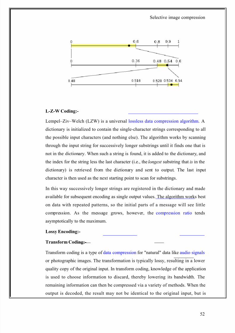
Arithmetic coding is a method for lossless data compression. Normally, a string of
characters such as the words "hello there" is represented using a fixed number of
bits per character, as in the ASCII code. Like Huffman coding, arithmetic coding is
a form of variable-length entropy encoding that converts a string into another form
that represents frequently used characters using fewer bits and infrequently used
characters using more bits, with the goal of using fewer bits in total. As opposed to
other entropy encoding techniques that separate the input message into its
component symbols and replace each symbol with a code word, arithmetic coding
encodes the entire message into a single number, a fraction n where (0.0 ≤ n < 1.0).
51
8/8/2019 Image Compression Black Book3
http://slidepdf.com/reader/full/image-compression-black-book3 52/73
Selective image compression
L-Z-W Coding:-
Lempel–Ziv–Welch (LZW) is a universal lossless data compression algorithm. A
dictionary is initialized to contain the single-character strings corresponding to all
the possible input characters (and nothing else). The algorithm works by scanning
through the input string for successively longer substrings until it finds one that is
not in the dictionary. When such a string is found, it is added to the dictionary, and
the index for the string less the last character (i.e., the longest substring that is in the
dictionary) is retrieved from the dictionary and sent to output. The last input
character is then used as the next starting point to scan for substrings.
In this way successively longer strings are registered in the dictionary and made
available for subsequent encoding as single output values. The algorithm works best
on data with repeated patterns, so the initial parts of a message will see little
compression. As the message grows, however, the compression ratio tends
asymptotically to the maximum.
Lossy Encoding:-
Transform Coding:-
Transform coding is a type of data compression for "natural" data like audio signals
or photographic images. The transformation is typically lossy, resulting in a lower
quality copy of the original input. In transform coding, knowledge of the application
is used to choose information to discard, thereby lowering its bandwidth. The
remaining information can then be compressed via a variety of methods. When the
output is decoded, the result may not be identical to the original input, but is
52
8/8/2019 Image Compression Black Book3
http://slidepdf.com/reader/full/image-compression-black-book3 53/73
Selective image compression
expected to be close enough for the purpose of the application.
53
8/8/2019 Image Compression Black Book3
http://slidepdf.com/reader/full/image-compression-black-book3 54/73
Selective image compression
SELECTIVE IMAGE COMPRESSION
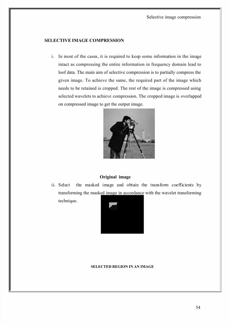
i. In most of the cases, it is required to keep some information in the imageintact as compressing the entire information in frequency domain lead to
loof data. The main aim of selective compression is to partially compress the
given image. To achieve the same, the required part of the image which
needs to be retained is cropped. The rest of the image is compressed using
selected wavelets to achieve compression. The cropped image is overlapped
on compressed image to get the output image.
Original image
ii. Select the masked image and obtain the transform coefficients by
transforming the masked image in accordance with the wavelet transforming
technique.
SELECTED REGION IN AN IMAGE
54
8/8/2019 Image Compression Black Book3
http://slidepdf.com/reader/full/image-compression-black-book3 55/73
Selective image compression
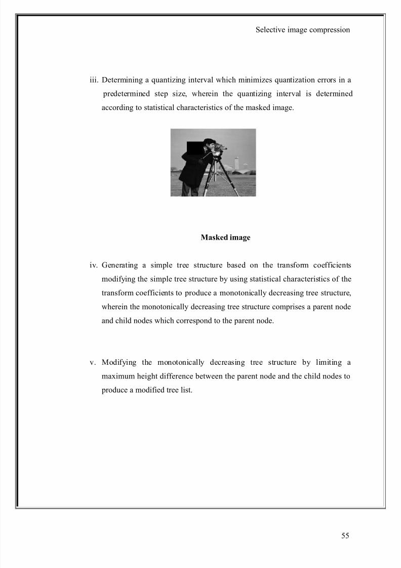
iii. Determining a quantizing interval which minimizes quantization errors in a
predetermined step size, wherein the quantizing interval is determined
according to statistical characteristics of the masked image.
Masked image
iv. Generating a simple tree structure based on the transform coefficients
modifying the simple tree structure by using statistical characteristics of the
transform coefficients to produce a monotonically decreasing tree structure,
wherein the monotonically decreasing tree structure comprises a parent node
and child nodes which correspond to the parent node.
v. Modifying the monotonically decreasing tree structure by limiting a
maximum height difference between the parent node and the child nodes to
produce a modified tree list.
55
8/8/2019 Image Compression Black Book3
http://slidepdf.com/reader/full/image-compression-black-book3 56/73
Selective image compression
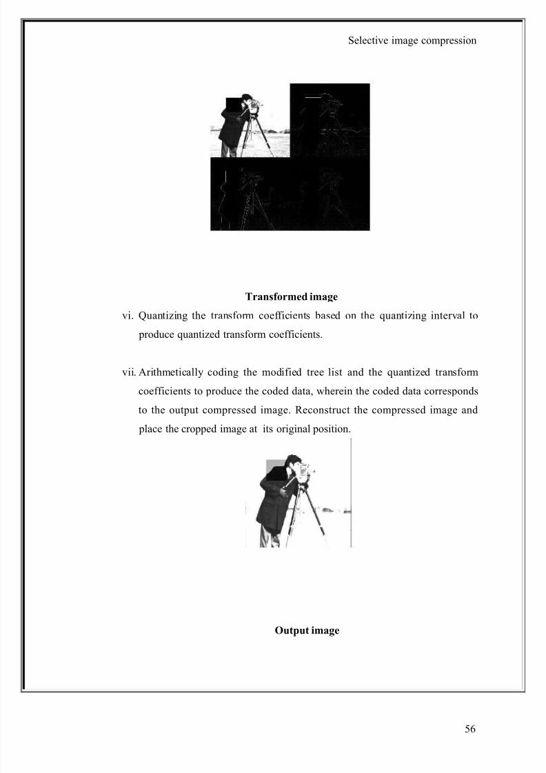
Transformed image
vi. Quantizing the transform coefficients based on the quantizing interval to
produce quantized transform coefficients.
vii. Arithmetically coding the modified tree list and the quantized transform
coefficients to produce the coded data, wherein the coded data corresponds
to the output compressed image. Reconstruct the compressed image and
place the cropped image at its original position.
Output image
56

8/8/2019 Image Compression Black Book3
http://slidepdf.com/reader/full/image-compression-black-book3 57/73
Selective image compression
57
8/8/2019 Image Compression Black Book3
http://slidepdf.com/reader/full/image-compression-black-book3 58/73
Selective image compression
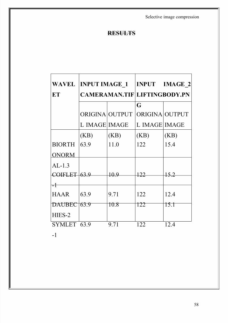
RESULTS
WAVEL
ET
INPUT IMAGE_1
CAMERAMAN.TIF
INPUT IMAGE_2
LIFTINGBODY.PN
G
ORIGINA
L IMAGE
(KB)
OUTPUT
IMAGE
(KB)
ORIGINA
L IMAGE
(KB)
OUTPUT
IMAGE
(KB)
BIORTH
ONORM
AL-1.3
63.9 11.0 122 15.4
COIFLET
-1
63.9 10.9 122 15.2
HAAR 63.9 9.71 122 12.4
DAUBEC
HIES-2
63.9 10.8 122 15.1
SYMLET-1
63.9 9.71 122 12.4
58
8/8/2019 Image Compression Black Book3
http://slidepdf.com/reader/full/image-compression-black-book3 59/73
8/8/2019 Image Compression Black Book3
http://slidepdf.com/reader/full/image-compression-black-book3 60/73
Selective image compression
In this paper, we found that wavelet-based image compression prefers smooth
functions of relatively short length.We have applied the input image to various
wavelets such as Daubuchies, Haar, Coiflets, Symlets and Biorthogonal for image
compression and then reconstructed the image. Our results show that differentwavelet filters performed differently for different images, but generally the
difference between each other was not great. As the results shown, HAAR and
SYMLET-1 are the best-suited wavelet filters for an in all compression bit rate and
it also aligns the cropped image more perfectly than others. But BIORTHOGONAL
wavelet shows worst result as compared to others. As conclusion, the choice of the
best performing wavelet filter in medical image compression is mostly depends on
the image content.
60

8/8/2019 Image Compression Black Book3
http://slidepdf.com/reader/full/image-compression-black-book3 61/73
8/8/2019 Image Compression Black Book3
http://slidepdf.com/reader/full/image-compression-black-book3 62/73
Selective image compression
The many benefits of image compression include less required storage
space, quicker sending and receiving of images, and less time lost on image
viewing and loading. But where and how is image compression used today?
The digital form of image compression is also being put to work in
industries such as fax transmission, satellite remote sensing, and high
definition television, etc.
In certain industries, the archiving of large numbers of images is required. A
good example is the health industry, where the constant scanning and/or
storage of medical images and documents take place. Image compression
offers many benefits here, as information can be stored without placing largeloads on system servers. Depending on the type of compression applied,
images can be compressed to save storage space, or to send to multiple
physicians for examination. And conveniently, these images can uncompress
when they are ready to be viewed, retaining the original high quality and
detail that medical imagery demands.
Image compression is also useful to any organization that requires the
viewing and storing of images to be standardized, such as a chain of retail
stores or a federal government agency. In the retail store example, the
introduction and placement of new products or the removal of discontinued
items can be much more easily completed when all employees receive, view
and process images in the same way. Federal government agencies that
standardize their image viewing, storage and transmitting processes can
eliminate large amounts of time spent in explanation and problem solving.
The time they save can then be applied to issues within the organization,
such as the improvement of government and employee programs.
In the security industry, image compression can greatly increase the
efficiency of recording, processing and storage. However, in this application
it is imperative to determine whether one compression standard will benefit
all areas. For example, in a video networking or closed-circuit television
62
8/8/2019 Image Compression Black Book3
http://slidepdf.com/reader/full/image-compression-black-book3 63/73
Selective image compression
application, several images at different frame rates may be required. Time is
also a consideration, as different areas may need to be recorded for various
lengths of time. Image resolution and quality also become considerations, as
does network bandwidth, and the overall security of the system.
Museums and galleries consider the quality of reproductions to be of the
utmost importance. Image compression, therefore, can be very effectively
applied in cases where accurate representations of museum or gallery items
are required, such as on a Web site. Detailed images that offer short
download times and easy viewing benefit all types of visitors, from the
student to the discriminating collector. Compressed images can also be used
in museum or gallery kiosks for the education of that establishment’svisitors. In a library scenario, students and enthusiasts from around the
world can view and enjoy a multitude of documents and texts without
having to incur traveling or lodging costs to do so.
Regardless of industry, image compression has virtually endless benefits
wherever improved storage, viewing and transmission of images are
required. And with the many image compression programs available today,
there is sure to be more than one that fits your requirements best.
63
8/8/2019 Image Compression Black Book3
http://slidepdf.com/reader/full/image-compression-black-book3 64/73
Selective image compression
FUTURE SCOPE
64

8/8/2019 Image Compression Black Book3
http://slidepdf.com/reader/full/image-compression-black-book3 65/73
Selective image compression
Our project basically aims at reducing storage space requirement and
transmission time during image data transfer so that cost effective
communication can be achieved.
Further developments can be made in order to achieve still better
compression ratio since use of the self similarity of images under different
scale is possible.
Further efforts can be made to develop a good Graphic User Interface so as
to make the software more user friendly.
65

8/8/2019 Image Compression Black Book3
http://slidepdf.com/reader/full/image-compression-black-book3 66/73
8/8/2019 Image Compression Black Book3
http://slidepdf.com/reader/full/image-compression-black-book3 67/73
Selective image compression
Selective image compression is a technique where explicitly defined
regions of interest are kept as it is, to maintain the important data and
compressing the remaining image.
Images require substantial storage and transmission resources, thus image
compression is advantageous to reduce these requirements.The main
advantages of the image compression are as follows: it saves memory space
for storage, channel bandwidth and the processing time for transmission.
Multiresolution is method, which allows certain parts of the signal to beresolved well in time, and other parts to be resolved well in frequency.
Multiresolution character of the wavelet decomposition leads to superior
energy compaction and perceptual quality of the decompressed image.
There are three methods which are used for image compression: Fourier
Transform, Cosine Transform and Wavelet Transform.
Important properties of wavelet functions in image compression applications
are compact support (lead to efficient implementation), symmetry (useful in
avoiding depbasing in image processing), orthogonal (allow fast algorithm),
regularity, and degree of smoothness (related to filter order).
There are many types of wavelets some wavelets have symmetry (valuable
in human vision perception) such as the Biorthogonal Wavelet pairs.
Shannon or “Sinc” Wavelets can find events with specific frequencies (these
are similar to the Sinc Function filters found in traditional DSP). Haar
Wavelets (the shortest) are good for edge detection and reconstructing
binary pulses. Coiflets Wavelets are good for data with self-similarities
(fractals).
Wavelet signifies small wave. It was first used in approximating a function
67
8/8/2019 Image Compression Black Book3
http://slidepdf.com/reader/full/image-compression-black-book3 68/73
Selective image compression
by linear combination of various waveforms obtained by translating and
scaling the wavelet at various position and scales. It was very old from the
time of Alfred Haars.
Wavelet uses the concept of Subband coding which uses two filters: low
pass filter and high pass filter. The low pass filter component retains almost
all distinguishable features of the original signal. And the high pass filter
component has little or no resemblance of the original signal. The low pass
component is again decomposed into two components.
The decomposition process can be continued up to the last possible level or up to a certain desired level.
As the high pass filter components have less information discernible to the
original signal, we can eliminate the information contents of the high pass
filters partially or significantly at each level of decomposition during the
reconstruction process.
It is this possibility of elimination of the information contents of the high
pass filter components that gives higher compression ratio in the case of
wavelet based image compression.
Quantization, involved in image processing, i s a lossy compression
technique achieved by compressing a range of values to a single quantum
value.
68

8/8/2019 Image Compression Black Book3
http://slidepdf.com/reader/full/image-compression-black-book3 69/73
Selective image compression
69
8/8/2019 Image Compression Black Book3
http://slidepdf.com/reader/full/image-compression-black-book3 70/73
8/8/2019 Image Compression Black Book3
http://slidepdf.com/reader/full/image-compression-black-book3 71/73
Selective image compression
71
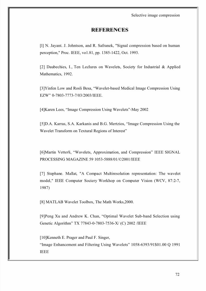
8/8/2019 Image Compression Black Book3
http://slidepdf.com/reader/full/image-compression-black-book3 72/73
Selective image compression
REFERENCES
[l] N. Jayant. J. Johntson, and R. Safranek, "Signal compression based on human
perception," Proc. IEEE, vo1.81, pp. 1385-1422, Oct. 1993.
[2] Daubechies, I., Ten LecIures on Wavelets, Society for Industrial & Applied
Mathematics, 1992.
[3]Yinfen Low and Rosli Besa, “Wavelet-based Medical Image Compression Using
EZW” 0-7803-7773-7/03/2003/IEEE.
[4]Karen Lees, “Image Compression Using Wavelets”-May 2002
[5]D.A. Karras, S.A. Karkanis and B.G. Mertzios, “Image Compression Using the
Wavelet Transform on Textural Regions of Interest”
[6]Martin Vetterli, “Wavelets, Approximation, and Compression” IEEE SIGNALPROCESSING MAGAZINE 59 1053-5888/01/©2001/IEEE
[7] Stephane. Mallat, "A Compact Multiresolution representation: The wavelet
model," IEEE Computer Sociery Workhop on Computer Vision (WCV, 87:2-7,
1987)
[8] MATLAB Wavelet Toolbox, The Math Works,2000.
[9]Peng Xu and Andrew K. Chan, “Optimal Wavelet Sub-band Selection using
Genetic Algorithm” TX 77843-0-7803-7536-X/ (C) 2002 /IEEE
[10]Kenneth E. Prager and Paul F. Singer,
“Image Enhancement and Filtering Using Wavelets” 1058-6393/91$01.00 Q 1991
IEEE
72
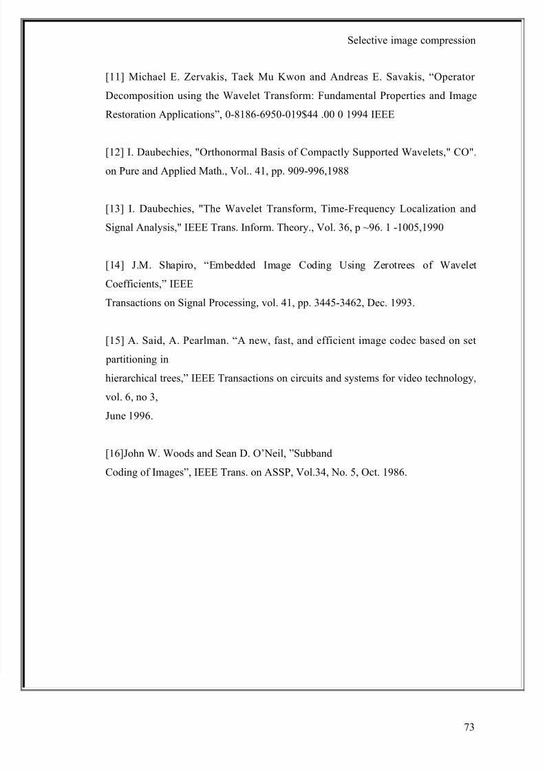
8/8/2019 Image Compression Black Book3
http://slidepdf.com/reader/full/image-compression-black-book3 73/73
Selective image compression
[11] Michael E. Zervakis, Taek Mu Kwon and Andreas E. Savakis, “Operator
Decomposition using the Wavelet Transform: Fundamental Properties and Image
Restoration Applications”, 0-8186-6950-019$44 .00 0 1994 IEEE
[12] I. Daubechies, "Orthonormal Basis of Compactly Supported Wavelets," CO".
on Pure and Applied Math., Vol.. 41, pp. 909-996,1988
[13] I. Daubechies, "The Wavelet Transform, Time-Frequency Localization and
Signal Analysis," IEEE Trans. Inform. Theory., Vol. 36, p ~96. 1 -1005,1990
[14] J.M. Shapiro, “Embedded Image Coding Using Zerotrees of WaveletCoefficients,” IEEE
Transactions on Signal Processing, vol. 41, pp. 3445-3462, Dec. 1993.
[15] A. Said, A. Pearlman. “A new, fast, and efficient image codec based on set
partitioning in
hierarchical trees,” IEEE Transactions on circuits and systems for video technology,
vol. 6, no 3,
June 1996.
[16]John W. Woods and Sean D. O’Neil, ”Subband
Coding of Images”, IEEE Trans. on ASSP, Vol.34, No. 5, Oct. 1986.