iMAc 17inc
156
© 20 02 Apple Comput er , In c. All ri gh ts re se rved. Service Source iMac (17-inch Flat Panel) Updated 18 March 2003
-
Upload
agruel-mendez-juan-ruperto -
Category
Documents
-
view
241 -
download
0
Transcript of iMAc 17inc
7/28/2019 iMAc 17inc
http://slidepdf.com/reader/full/imac-17inc 1/156
© 2002 Apple Computer Inc Al l rights reserved
Service Source
iMac (17-inch Flat Panel) Updated 18 March 2003

7/28/2019 iMAc 17inc
http://slidepdf.com/reader/full/imac-17inc 2/156
© 2002 Apple Computer Inc Al l rights reserved
Service Source
Take Apart
iMac (17-inch Flat Panel)
7/28/2019 iMAc 17inc
http://slidepdf.com/reader/full/imac-17inc 3/156
iM (17 i h Fl t P l) T k A t 1T l
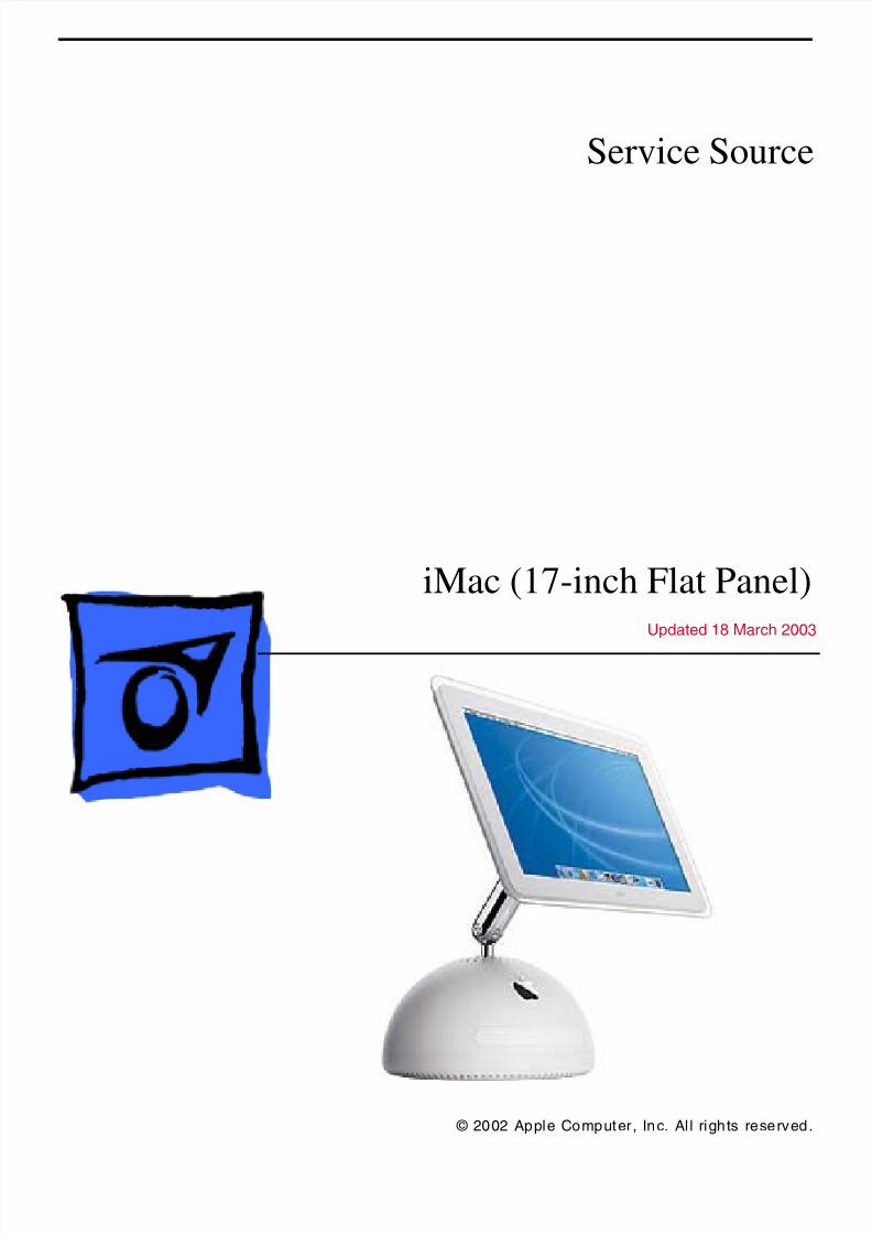
Tools
The following tools are recommended for the take apart procedures.
• service repair kit (076-0900) includes:
– the service stand (076-0898)
– diagnostic cables (076-0897)
• thermal paste (922-4757)
• torque dr iver (076-0899)
• 1.5 mm hex driver (for LCD bezel screws)
• phillips #0 screwdriver)
• torx screwdriver set (6, 8, 10, 15, 25)
• plastic flatblade screwdriver or stylus
• needlenose pliers
• ESD wriststrap and mat
Service Stand
7/28/2019 iMAc 17inc
http://slidepdf.com/reader/full/imac-17inc 4/156
2 iM (17 i h Fl t P l) T k A t T l
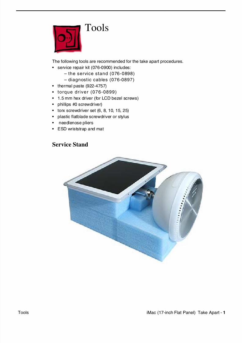
1. Support the computer by neck and the base (A). Gently position the computer in the
service stand with the flat panel facing up (B).
2. Note: The base of the computer can be rotated when servicing internal parts.
7/28/2019 iMAc 17inc
http://slidepdf.com/reader/full/imac-17inc 5/156
iM (17 i h Fl t P l) T k A t 3U A Pl t
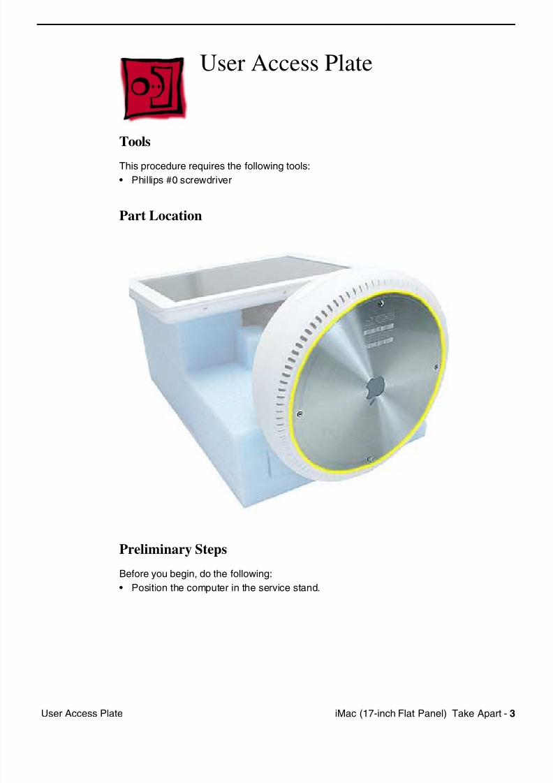
User Access Plate
Tools
This procedure requires the following tools:
• Phillips #0 screwdriver
Part Location
Preliminary Steps
Before you begin, do the following:
• Position the computer in the service stand.
7/28/2019 iMAc 17inc
http://slidepdf.com/reader/full/imac-17inc 6/156
4 iM (17 i h Fl t P l) T k A t U A Pl t
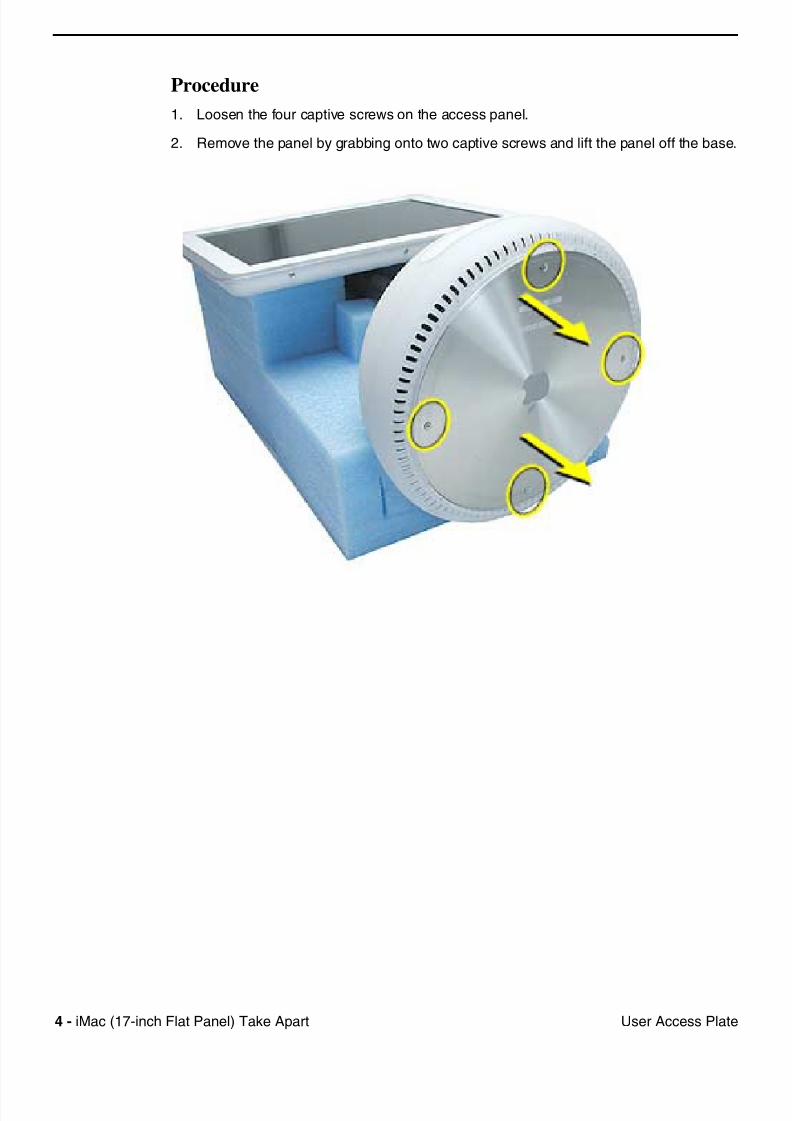
Procedure
1. Loosen the four captive screws on the access panel.
2. Remove the panel by grabbing onto two captive screws and lift the panel off the base.
7/28/2019 iMAc 17inc
http://slidepdf.com/reader/full/imac-17inc 7/156
iM (17 i h Fl t P l) T k A t 5Ai P t C d
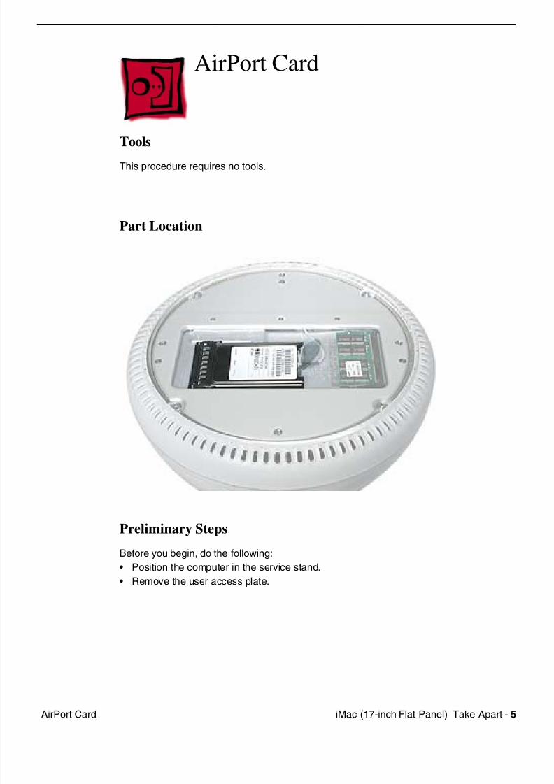
AirPort Card
Tools
This procedure requires no tools.
Part Location
Preliminary Steps
Before you begin, do the following:
• Position the computer in the service stand.
• Remove the user access plate.
7/28/2019 iMAc 17inc
http://slidepdf.com/reader/full/imac-17inc 8/156
6 iM (17 i h Fl t P l) T k A t Ai P t C d
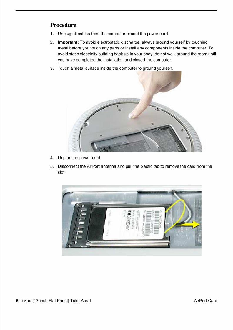
Procedure
1. Unplug all cables from the computer except the power cord.
2. Important: To avoid electrostatic discharge, always ground yourself by touching
metal before you touch any parts or install any components inside the computer. To
avoid static electricity building back up in your body, do not walk around the room until
you have completed the installation and closed the computer.
3. Touch a metal surface inside the computer to ground yourself.
4. Unplug the power cord.
5. Disconnect the AirPort antenna and pull the plastic tab to remove the card from the
slot.
7/28/2019 iMAc 17inc
http://slidepdf.com/reader/full/imac-17inc 9/156
iM (17 i h Fl t P l) T k A t 7M SO DIMM ( i t ll bl )
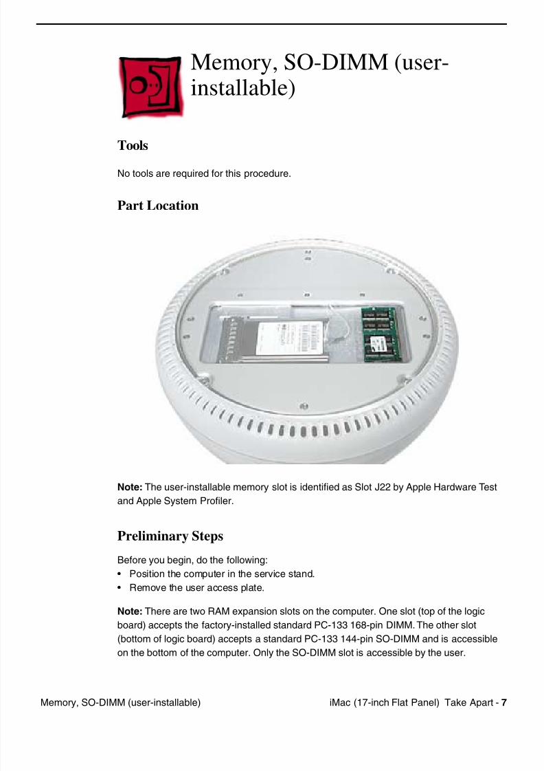
Memory, SO-DIMM (user-installable)
Tools
No tools are required for this procedure.
Part Location
Note: The user-installable memory slot is identified as Slot J22 by Apple Hardware Test
and Apple System Profiler.
Preliminary StepsBefore you begin, do the following:
• Position the computer in the service stand.
• Remove the user access plate.
Note: There are two RAM expansion slots on the computer. One slot (top of the logic
board) accepts the factory-installed standard PC-133 168-pin DIMM. The other slot
(bottom of logic board) accepts a standard PC-133 144-pin SO-DIMM and is accessible
on the bottom of the computer. Only the SO-DIMM slot is accessible by the user.
7/28/2019 iMAc 17inc
http://slidepdf.com/reader/full/imac-17inc 10/156
8 iM (17 i h Fl t P l) T k A t M SO DIMM ( i t ll bl )
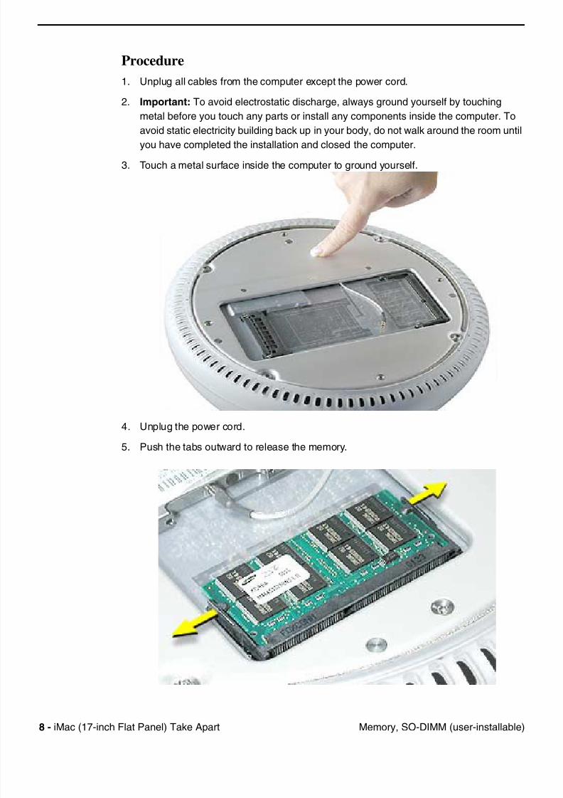
Procedure
1. Unplug all cables from the computer except the power cord.
2. Important: To avoid electrostatic discharge, always ground yourself by touching
metal before you touch any parts or install any components inside the computer. To
avoid static electricity building back up in your body, do not walk around the room until
you have completed the installation and closed the computer.
3. Touch a metal surface inside the computer to ground yourself.
4. Unplug the power cord.
5. Push the tabs outward to release the memory.
7/28/2019 iMAc 17inc
http://slidepdf.com/reader/full/imac-17inc 11/156
iM (17 i h Fl t P l) T k A t 9M SO DIMM ( i t ll bl )
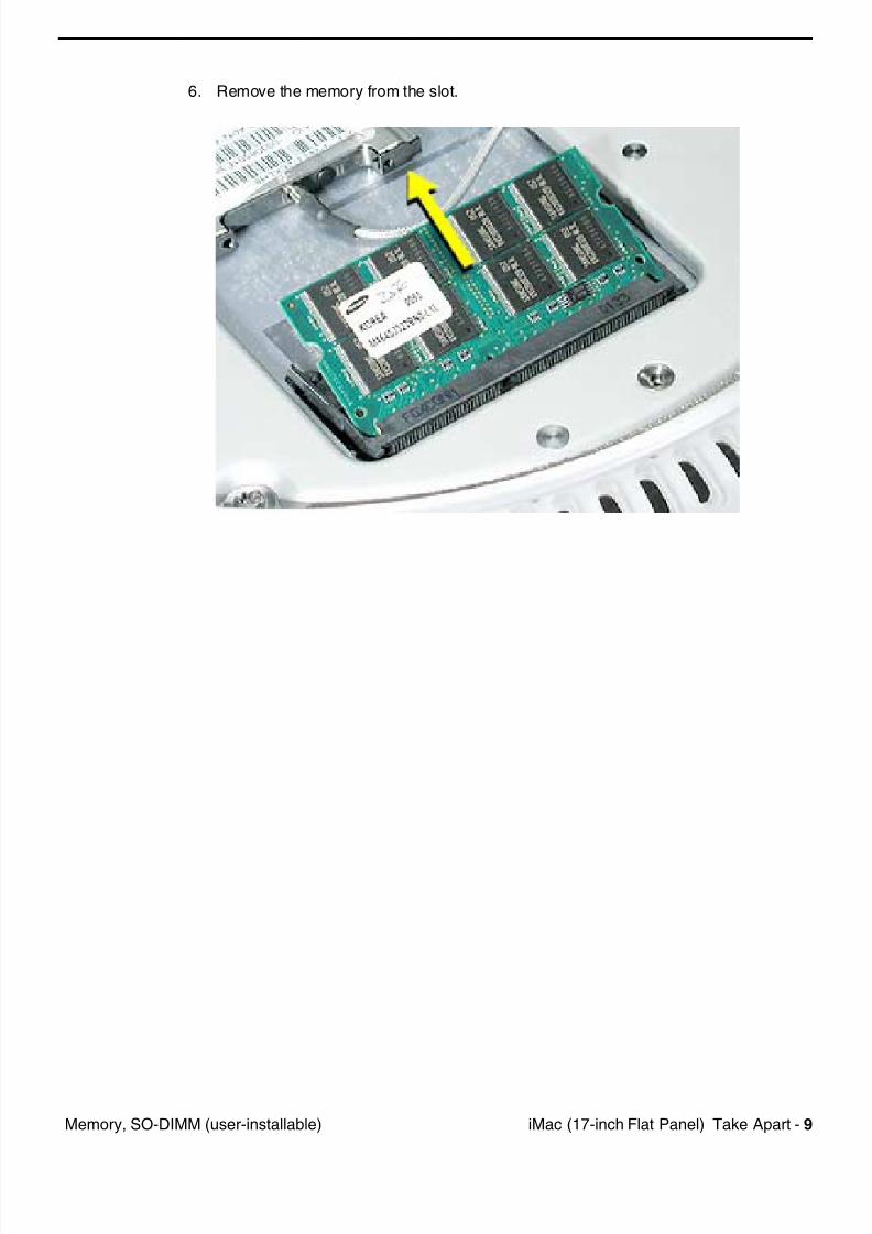
6. Remove the memory from the slot.
7/28/2019 iMAc 17inc
http://slidepdf.com/reader/full/imac-17inc 12/156
10 iM (17 i h Fl t P l) T k A t B tt H i
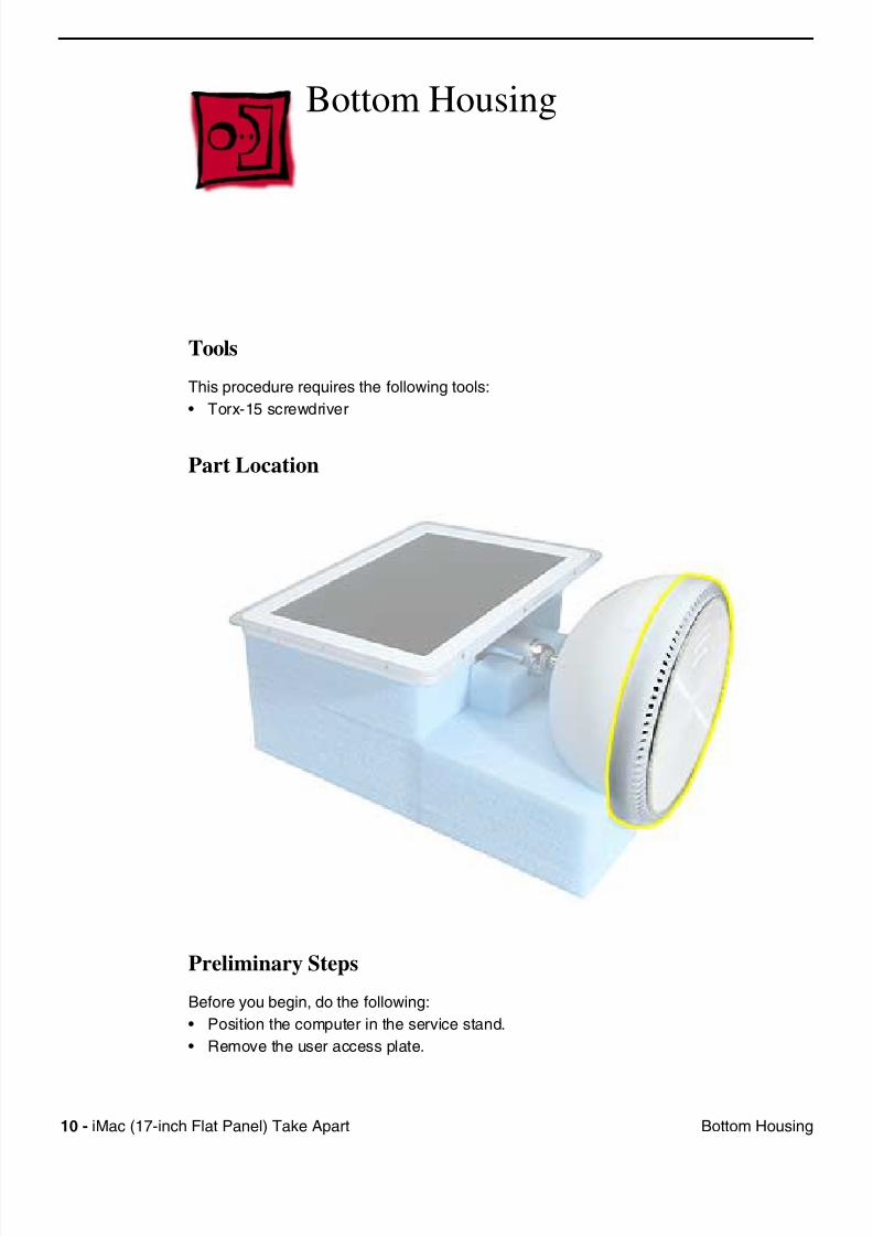
Bottom Housing
Tools
This procedure requires the following tools:
• Torx-15 screwdriver
Part Location
Preliminary Steps
Before you begin, do the following:
• Position the computer in the service stand.
• Remove the user access plate.
7/28/2019 iMAc 17inc
http://slidepdf.com/reader/full/imac-17inc 13/156
iM (17 i h Fl t P l) T k A t 11
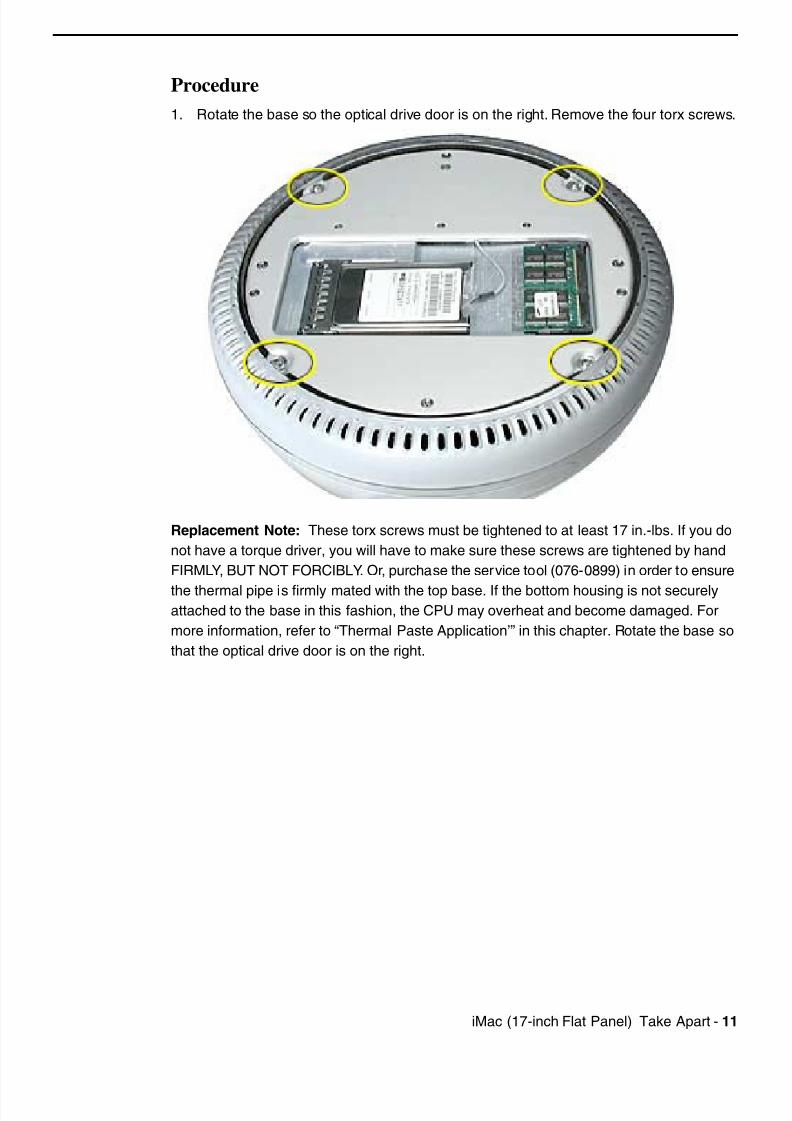
Procedure
1. Rotate the base so the optical drive door is on the right. Remove the four torx screws.
Replacement Note: These torx screws must be tightened to at least 17 in.-lbs. If you do
not have a torque driver, you will have to make sure these screws are tightened by hand
FIRMLY, BUT NOT FORCIBLY. Or, purchase the service tool (076-0899) in order to ensure
the thermal pipe is firmly mated with the top base. If the bottom housing is not securelyattached to the base in this fashion, the CPU may overheat and become damaged. For
more information, refer to “Thermal Paste Application’” in this chapter. Rotate the base so
that the optical drive door is on the right.
7/28/2019 iMAc 17inc
http://slidepdf.com/reader/full/imac-17inc 14/156
12 iM (17 i h Fl t P l) T k A t
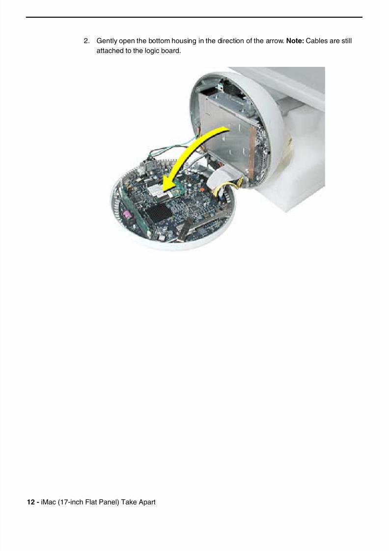
2. Gently open the bottom housing in the direction of the arrow. Note: Cables are still
attached to the logic board.
7/28/2019 iMAc 17inc
http://slidepdf.com/reader/full/imac-17inc 15/156
iM (17 i h Fl t P l) T k A t 13
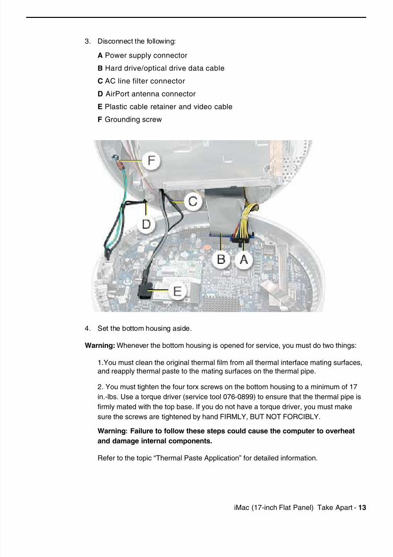
3. Disconnect the following:
A Power supply connector
B Hard drive/optical drive data cable
C AC line filter connector
D AirPort antenna connectorE Plastic cable retainer and video cable
F Grounding screw
4. Set the bottom housing aside.
Warning: Whenever the bottom housing is opened for service, you must do two things:
1.You must clean the original thermal film from all thermal interface mating surfaces,
and reapply thermal paste to the mating surfaces on the thermal pipe.
2. You must tighten the four torx screws on the bottom housing to a minimum of 17in.-lbs. Use a torque driver (service tool 076-0899) to ensure that the thermal pipe is
firmly mated with the top base. If you do not have a torque driver, you must make
sure the screws are tightened by hand FIRMLY, BUT NOT FORCIBLY.
Warning: Failure to follow these steps could cause the computer to overheat
and damage internal components.
Refer to the topic “Thermal Paste Application” for detailed information.
7/28/2019 iMAc 17inc
http://slidepdf.com/reader/full/imac-17inc 16/156
14 iM (17 i h Fl t P l) T k A t Th l P t A li ti
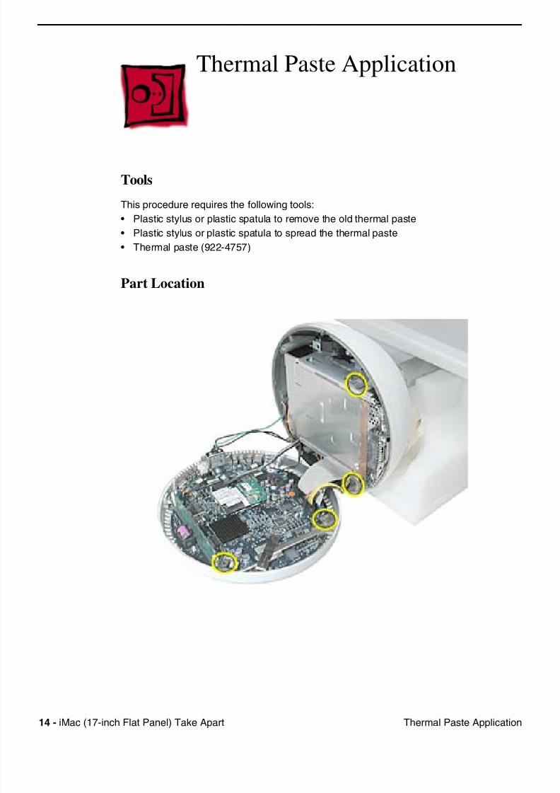
Thermal Paste Application
Tools
This procedure requires the following tools:
• Plastic stylus or plastic spatula to remove the old thermal paste
• Plastic stylus or plastic spatula to spread the thermal paste
• Thermal paste (922-4757)
Part Location
7/28/2019 iMAc 17inc
http://slidepdf.com/reader/full/imac-17inc 17/156
iM (17 i h Fl t P l) T k A t 15Th l P t A li ti
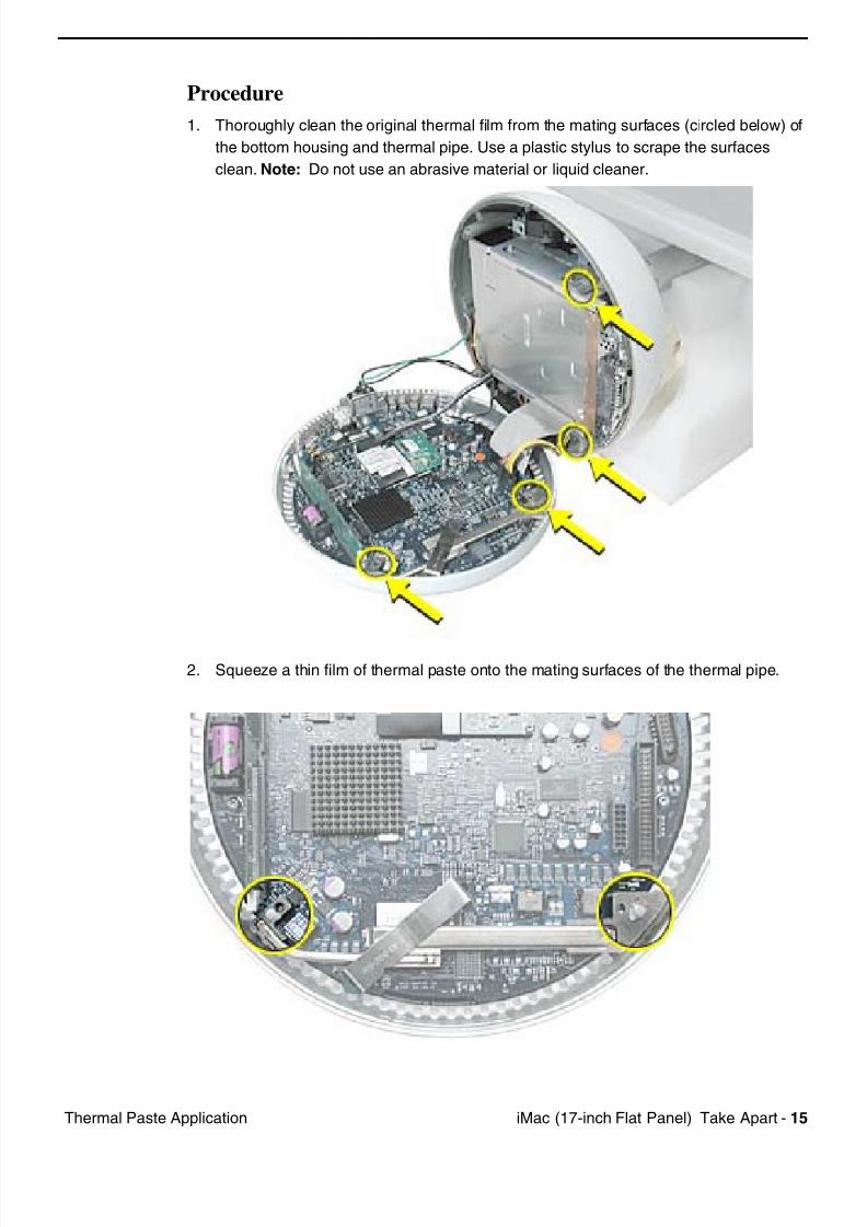
Procedure
1. Thoroughly clean the original thermal film from the mating surfaces (circled below) of
the bottom housing and thermal pipe. Use a plastic stylus to scrape the surfaces
clean. Note: Do not use an abrasive material or liquid cleaner.
2. Squeeze a thin film of thermal paste onto the mating surfaces of the thermal pipe.

7/28/2019 iMAc 17inc
http://slidepdf.com/reader/full/imac-17inc 18/156
16 iM (17 i h Fl t P l) T k A t Th l P t A li ti
3. Replace the bottom housing.
Warning: The bottom housing has four torx screws that must be tightened to at least
17 in.-lbs. Use a torque driver (service tool 076-0899) to ensure that the thermal pipe
is firmly mated with the top base. If you do not have a torque driver, you must make
sure the screws are tightened by hand FIRMLY, BUT NOT FORCIBLY.
Warning: Failure to apply the thermal paste as described in this procedure, and
failure to tighten the torx screws as directed, could cause the computer to
overheat and damage internal components.
Refer to the topic “Thermal Paste Application” for detailed information.
7/28/2019 iMAc 17inc
http://slidepdf.com/reader/full/imac-17inc 19/156
iM (17 i h Fl t P l) T k A t 17RJ 11 M d Filt B d
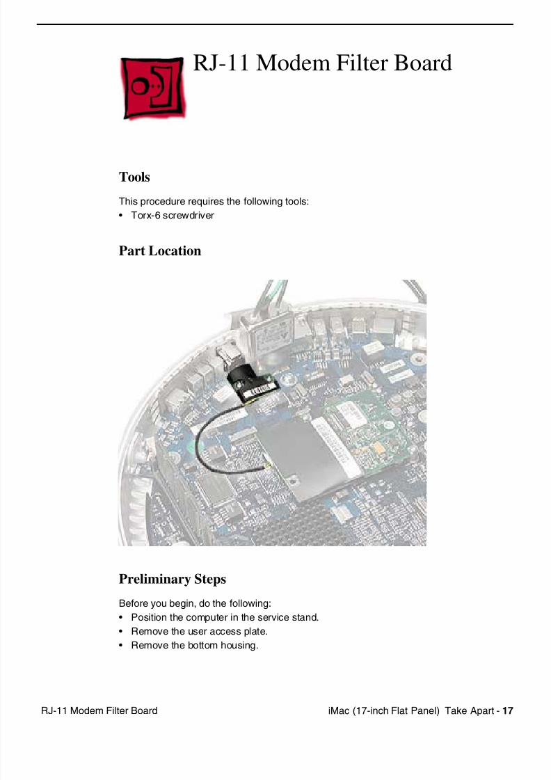
RJ-11 Modem Filter Board
Tools
This procedure requires the following tools:
• Torx-6 screwdriver
Part Location
Preliminary Steps
Before you begin, do the following:
• Position the computer in the service stand.
• Remove the user access plate.
• Remove the bottom housing.
7/28/2019 iMAc 17inc
http://slidepdf.com/reader/full/imac-17inc 20/156
18 iM (17 i h Fl t P l) T k A t RJ 11 M d Filt B d
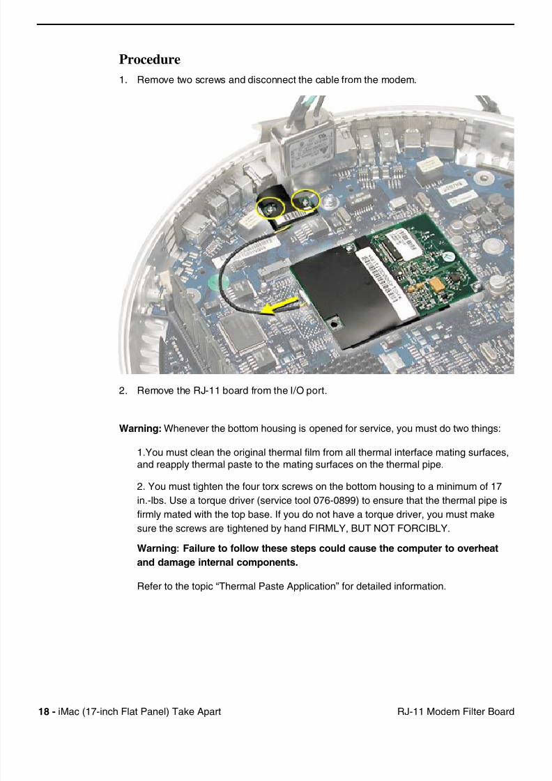
Procedure
1. Remove two screws and disconnect the cable from the modem.
2. Remove the RJ-11 board from the I/O port.
Warning: Whenever the bottom housing is opened for service, you must do two things:
1.You must clean the original thermal film from all thermal interface mating surfaces,
and reapply thermal paste to the mating surfaces on the thermal pipe.
2. You must tighten the four torx screws on the bottom housing to a minimum of 17
in.-lbs. Use a torque driver (service tool 076-0899) to ensure that the thermal pipe is
firmly mated with the top base. If you do not have a torque driver, you must make
sure the screws are tightened by hand FIRMLY, BUT NOT FORCIBLY.
Warning: Failure to follow these steps could cause the computer to overheatand damage internal components.
Refer to the topic “Thermal Paste Application” for detailed information.
7/28/2019 iMAc 17inc
http://slidepdf.com/reader/full/imac-17inc 21/156
iM (17 i h Fl t P l) T k A t 19M d
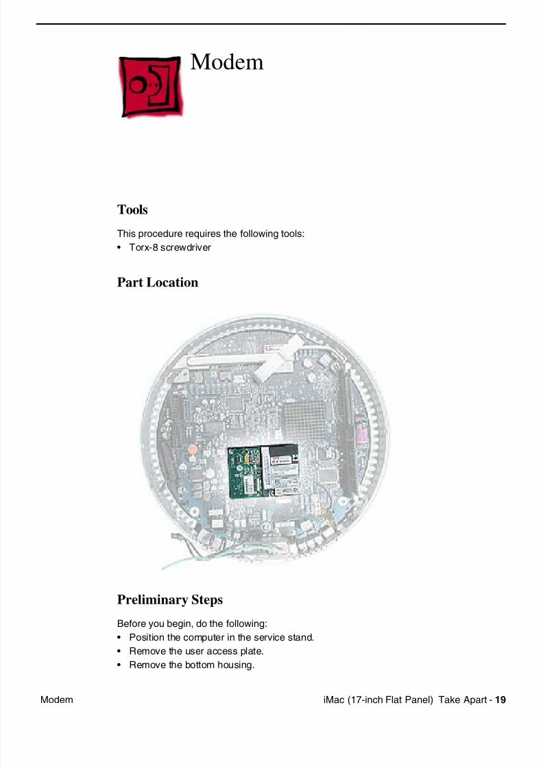
Modem
Tools
This procedure requires the following tools:
• Torx-8 screwdriver
Part Location
Preliminary Steps
Before you begin, do the following:
• Position the computer in the service stand.
• Remove the user access plate.
• Remove the bottom housing.
7/28/2019 iMAc 17inc
http://slidepdf.com/reader/full/imac-17inc 22/156
20 iM (17 i h Fl t P l) T k A t M d
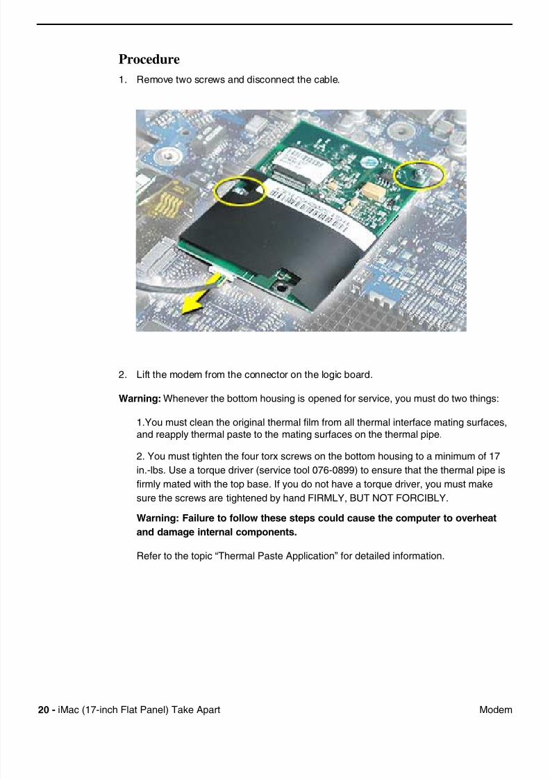
Procedure
1. Remove two screws and disconnect the cable.
2. Lift the modem from the connector on the logic board.
Warning: Whenever the bottom housing is opened for service, you must do two things:
1.You must clean the original thermal film from all thermal interface mating surfaces,
and reapply thermal paste to the mating surfaces on the thermal pipe.
2. You must tighten the four torx screws on the bottom housing to a minimum of 17
in.-lbs. Use a torque driver (service tool 076-0899) to ensure that the thermal pipe is
firmly mated with the top base. If you do not have a torque driver, you must make
sure the screws are tightened by hand FIRMLY, BUT NOT FORCIBLY.
Warning: Failure to follow these steps could cause the computer to overheat
and damage internal components.
Refer to the topic “Thermal Paste Application” for detailed information.
7/28/2019 iMAc 17inc
http://slidepdf.com/reader/full/imac-17inc 23/156
iM (17 i h Fl t P l) T k A t 21M (f t i t ll d)
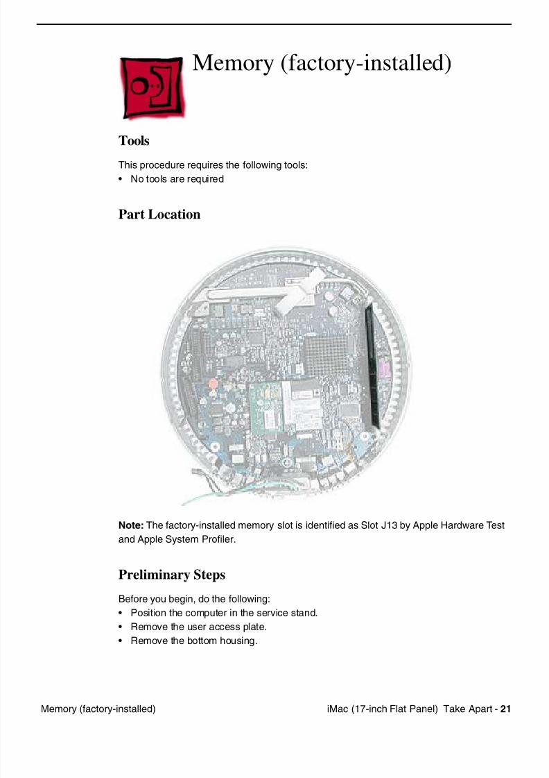
Memory (factory-installed)
Tools
This procedure requires the following tools:
• No tools are required
Part Location
Note: The factory-installed memory slot is identified as Slot J13 by Apple Hardware Test
and Apple System Profiler.
Preliminary Steps
Before you begin, do the following:
• Position the computer in the service stand.
• Remove the user access plate.
• Remove the bottom housing.
7/28/2019 iMAc 17inc
http://slidepdf.com/reader/full/imac-17inc 24/156
22 iM (17 i h Fl t P l) T k A t M (f t i t ll d)
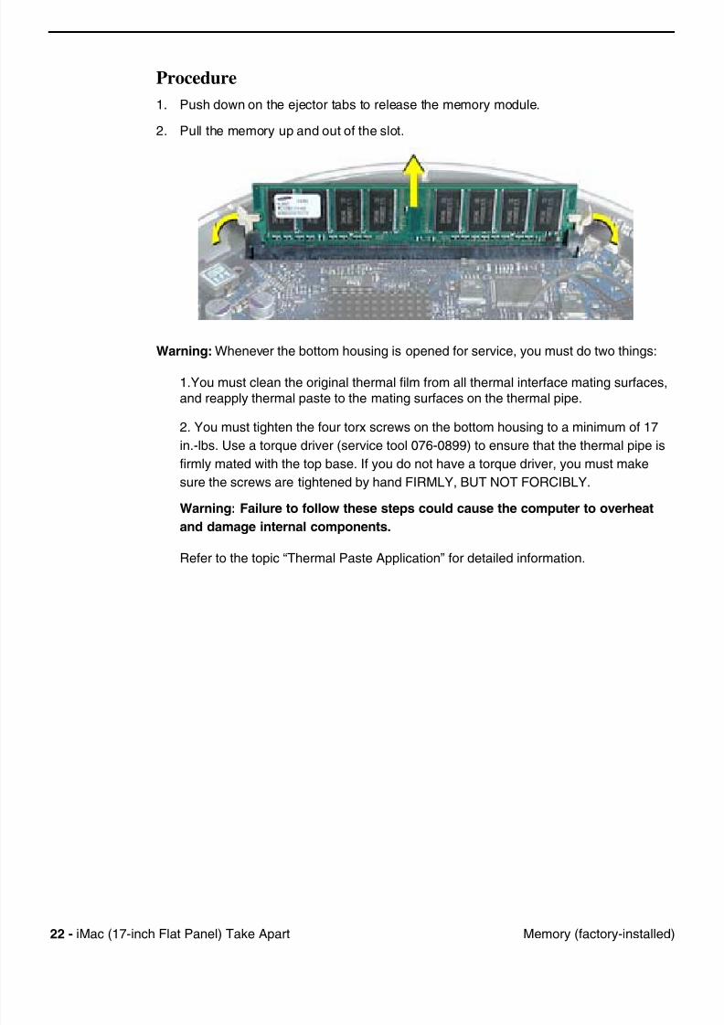
Procedure
1. Push down on the ejector tabs to release the memory module.
2. Pull the memory up and out of the slot.
Warning: Whenever the bottom housing is opened for service, you must do two things:
1.You must clean the original thermal film from all thermal interface mating surfaces,
and reapply thermal paste to the mating surfaces on the thermal pipe.
2. You must tighten the four torx screws on the bottom housing to a minimum of 17
in.-lbs. Use a torque driver (service tool 076-0899) to ensure that the thermal pipe is
firmly mated with the top base. If you do not have a torque driver, you must make
sure the screws are tightened by hand FIRMLY, BUT NOT FORCIBLY.
Warning: Failure to follow these steps could cause the computer to overheat
and damage internal components.
Refer to the topic “Thermal Paste Application” for detailed information.
7/28/2019 iMAc 17inc
http://slidepdf.com/reader/full/imac-17inc 25/156
iM (17 i h Fl t P l) T k A t 23B tt
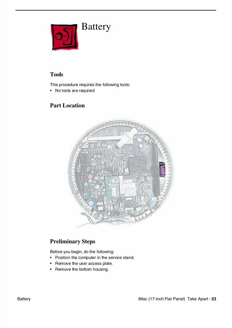
Battery
Tools
This procedure requires the following tools:
• No tools are required
Part Location
Preliminary Steps
Before you begin, do the following:
• Position the computer in the service stand.
• Remove the user access plate.
• Remove the bottom housing.
7/28/2019 iMAc 17inc
http://slidepdf.com/reader/full/imac-17inc 26/156
24 iM (17 i h Fl t P l) T k A t B tt
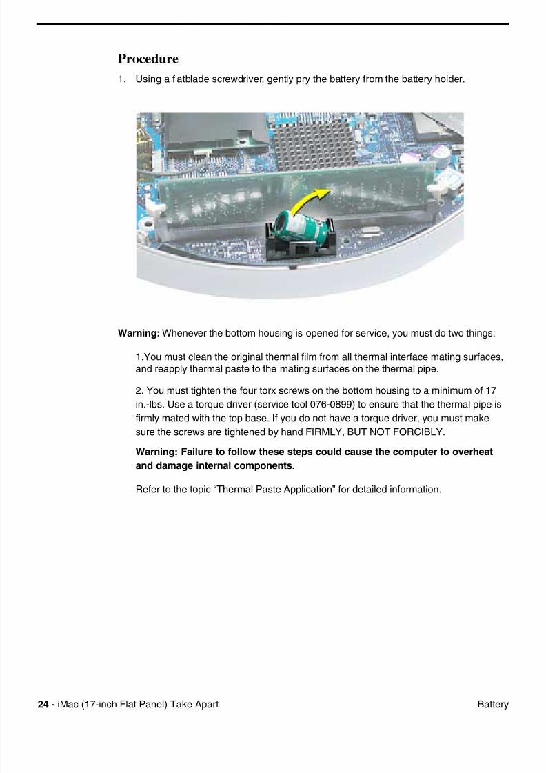
Procedure
1. Using a flatblade screwdriver, gently pry the battery from the battery holder.
Warning: Whenever the bottom housing is opened for service, you must do two things:
1.You must clean the original thermal film from all thermal interface mating surfaces,
and reapply thermal paste to the mating surfaces on the thermal pipe.
2. You must tighten the four torx screws on the bottom housing to a minimum of 17
in.-lbs. Use a torque driver (service tool 076-0899) to ensure that the thermal pipe isfirmly mated with the top base. If you do not have a torque driver, you must make
sure the screws are tightened by hand FIRMLY, BUT NOT FORCIBLY.
Warning: Failure to follow these steps could cause the computer to overheat
and damage internal components.
Refer to the topic “Thermal Paste Application” for detailed information.
7/28/2019 iMAc 17inc
http://slidepdf.com/reader/full/imac-17inc 27/156
iM (17 i h Fl t P l) T k A t 25L i B d
Logic Board
Tools
This procedure requires the following tools:
• Phillips #2 screwdriver (for the plastic screw)
• Torx-15 screwdriver
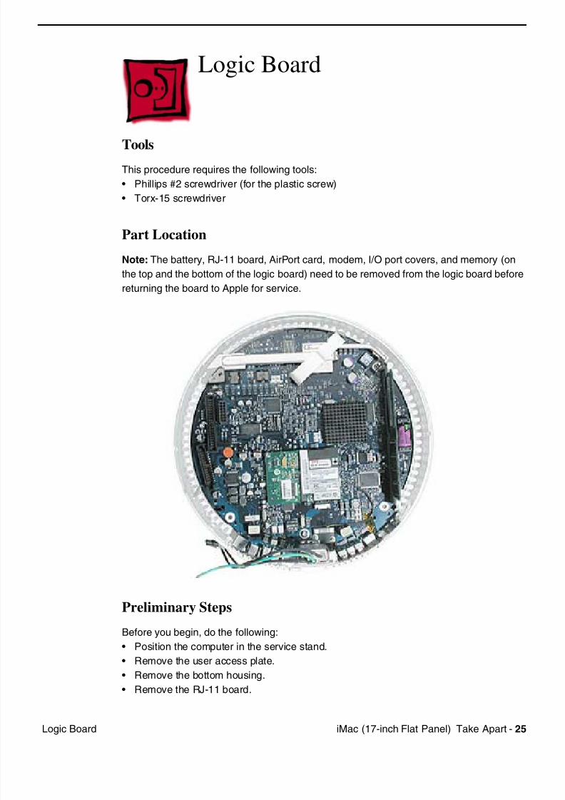
Part Location
Note: The battery, RJ-11 board, AirPort card, modem, I/O port covers, and memory (on
the top and the bottom of the logic board) need to be removed from the logic board before
returning the board to Apple for service.
Preliminary Steps
Before you begin, do the following:
• Position the computer in the service stand.
• Remove the user access plate.
• Remove the bottom housing.
• Remove the RJ-11 board.
7/28/2019 iMAc 17inc
http://slidepdf.com/reader/full/imac-17inc 28/156
26 iM (17 i h Fl t P l) T k A t L i B d
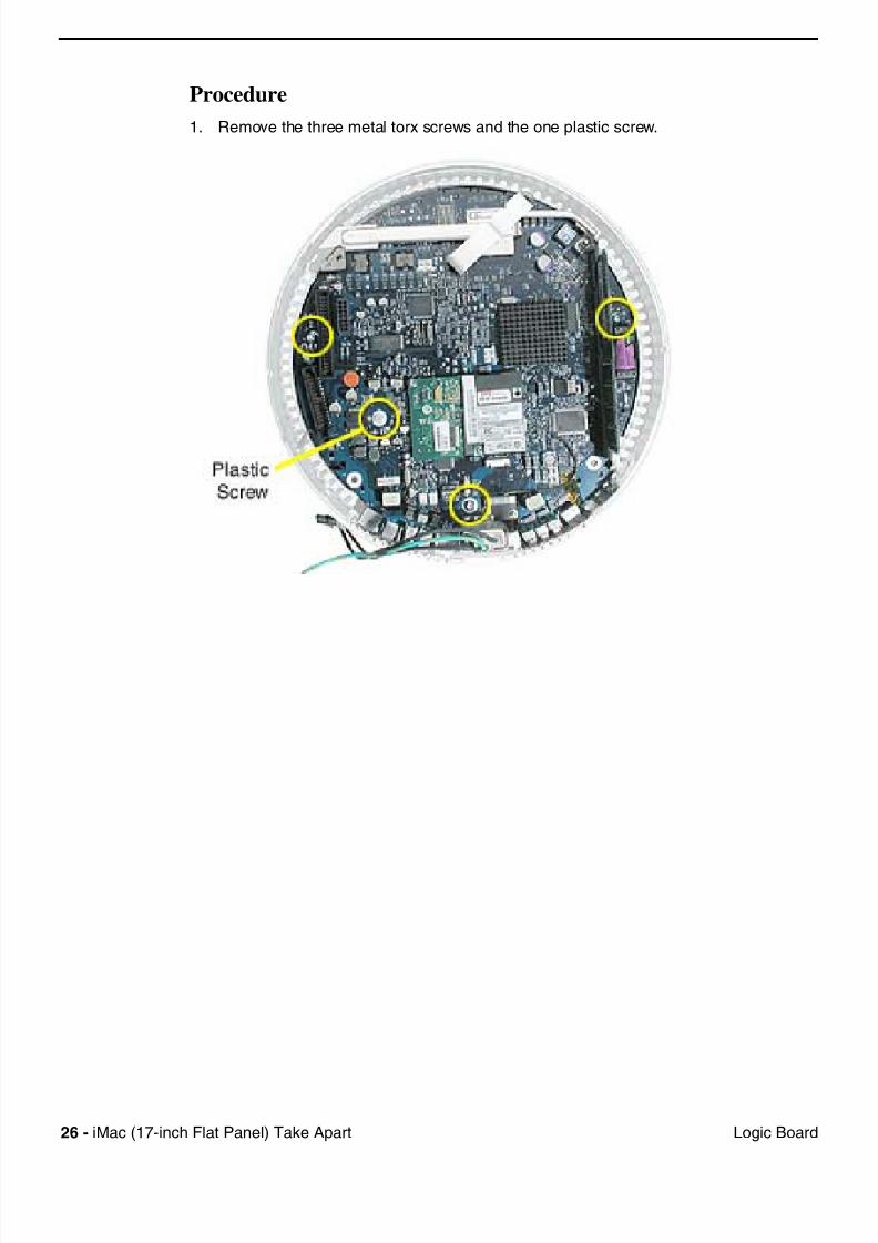
Procedure
1. Remove the three metal torx screws and the one plastic screw.
7/28/2019 iMAc 17inc
http://slidepdf.com/reader/full/imac-17inc 29/156
iM (17 i h Fl t P l) T k A t 27L i B d
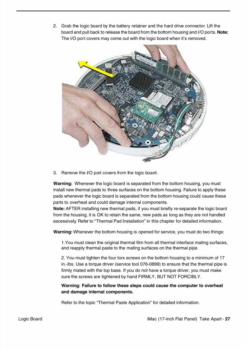
2. Grab the logic board by the battery retainer and the hard drive connector. Lift the
board and pull back to release the board from the bottom housing and I/O ports. Note:
The I/O port covers may come out with the logic board when it’s removed.
3. Remove the I/O port covers from the logic board.
Warning: Whenever the logic board is separated from the bottom housing, you mustinstall new thermal pads to three surfaces on the bottom housing. Failure to apply these
pads whenever the logic board is separated from the bottom housing could cause these
parts to overheat and could damage internal components.
Note: AFTER installing new thermal pads, if you must briefly re-separate the logic board
from the housing, it is OK to retain the same, new pads as long as they are not handled
excessively. Refer to “Thermal Pad Installation” in this chapter for detailed information.
Warning: Whenever the bottom housing is opened for service, you must do two things:
1.You must clean the original thermal film from all thermal interface mating surfaces,
and reapply thermal paste to the mating surfaces on the thermal pipe.
2. You must tighten the four torx screws on the bottom housing to a minimum of 17
in.-lbs. Use a torque driver (service tool 076-0899) to ensure that the thermal pipe is
firmly mated with the top base. If you do not have a torque driver, you must make
sure the screws are tightened by hand FIRMLY, BUT NOT FORCIBLY.
Warning: Failure to follow these steps could cause the computer to overheat
and damage internal components.
Refer to the topic “Thermal Paste Application” for detailed information.
7/28/2019 iMAc 17inc
http://slidepdf.com/reader/full/imac-17inc 30/156
28 iM (17 i h Fl t P l) T k A t I/O P t C
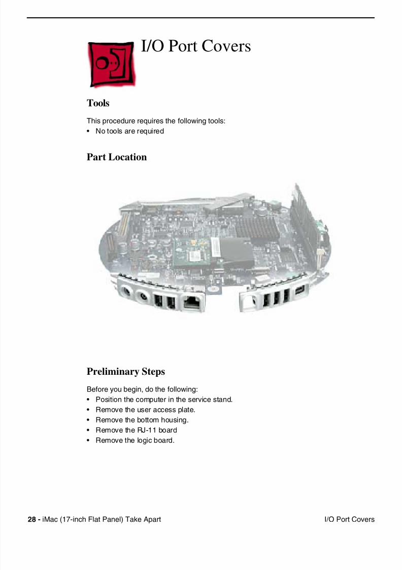
I/O Port Covers
Tools
This procedure requires the following tools:
• No tools are required
Part Location
Preliminary Steps
Before you begin, do the following:
• Position the computer in the service stand.• Remove the user access plate.
• Remove the bottom housing.
• Remove the RJ-11 board
• Remove the logic board.
7/28/2019 iMAc 17inc
http://slidepdf.com/reader/full/imac-17inc 31/156
iM (17 i h Fl t P l) T k A t 29I/O P t C
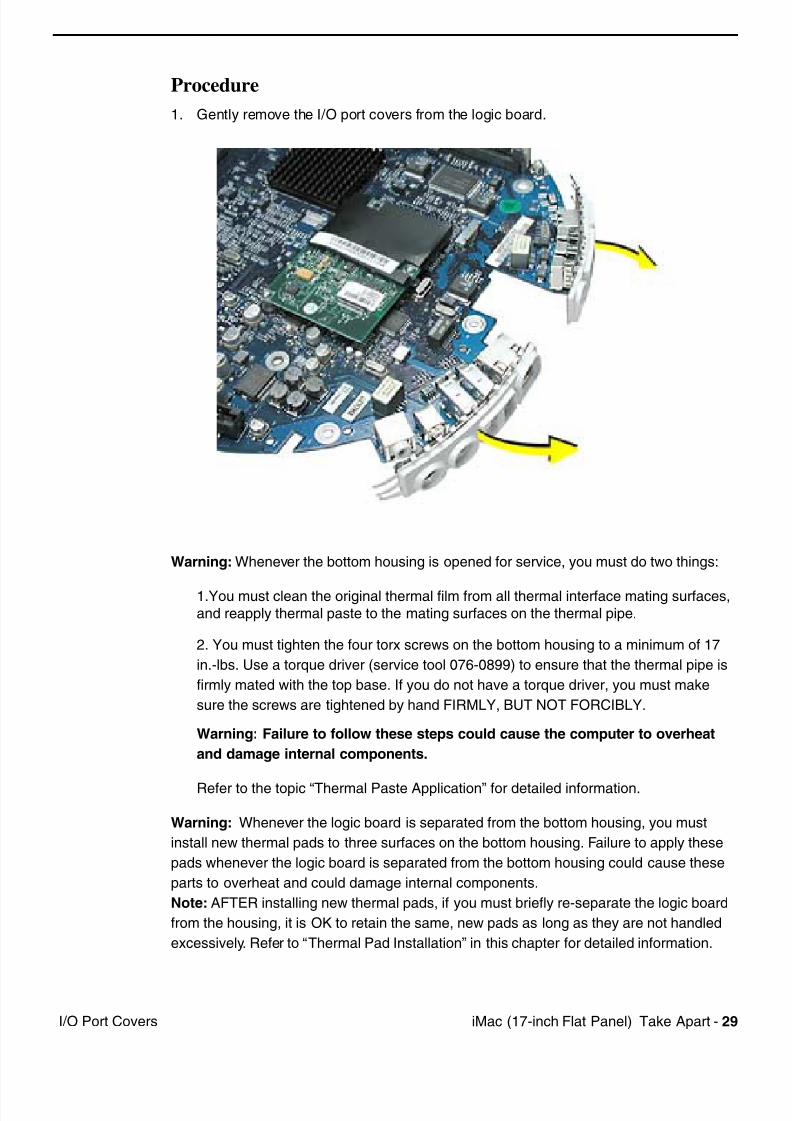
Procedure
1. Gently remove the I/O port covers from the logic board.
Warning: Whenever the bottom housing is opened for service, you must do two things:
1.You must clean the original thermal film from all thermal interface mating surfaces,
and reapply thermal paste to the mating surfaces on the thermal pipe.
2. You must tighten the four torx screws on the bottom housing to a minimum of 17
in.-lbs. Use a torque driver (service tool 076-0899) to ensure that the thermal pipe is
firmly mated with the top base. If you do not have a torque driver, you must make
sure the screws are tightened by hand FIRMLY, BUT NOT FORCIBLY.
Warning: Failure to follow these steps could cause the computer to overheat
and damage internal components.
Refer to the topic “Thermal Paste Application” for detailed information.
Warning: Whenever the logic board is separated from the bottom housing, you must
install new thermal pads to three surfaces on the bottom housing. Failure to apply these
pads whenever the logic board is separated from the bottom housing could cause these
parts to overheat and could damage internal components.
Note: AFTER installing new thermal pads, if you must briefly re-separate the logic board
from the housing, it is OK to retain the same, new pads as long as they are not handled
excessively. Refer to “Thermal Pad Installation” in this chapter for detailed information.
7/28/2019 iMAc 17inc
http://slidepdf.com/reader/full/imac-17inc 32/156
30 iM (17 i h Fl t P l) T k A t A t E t i C bl
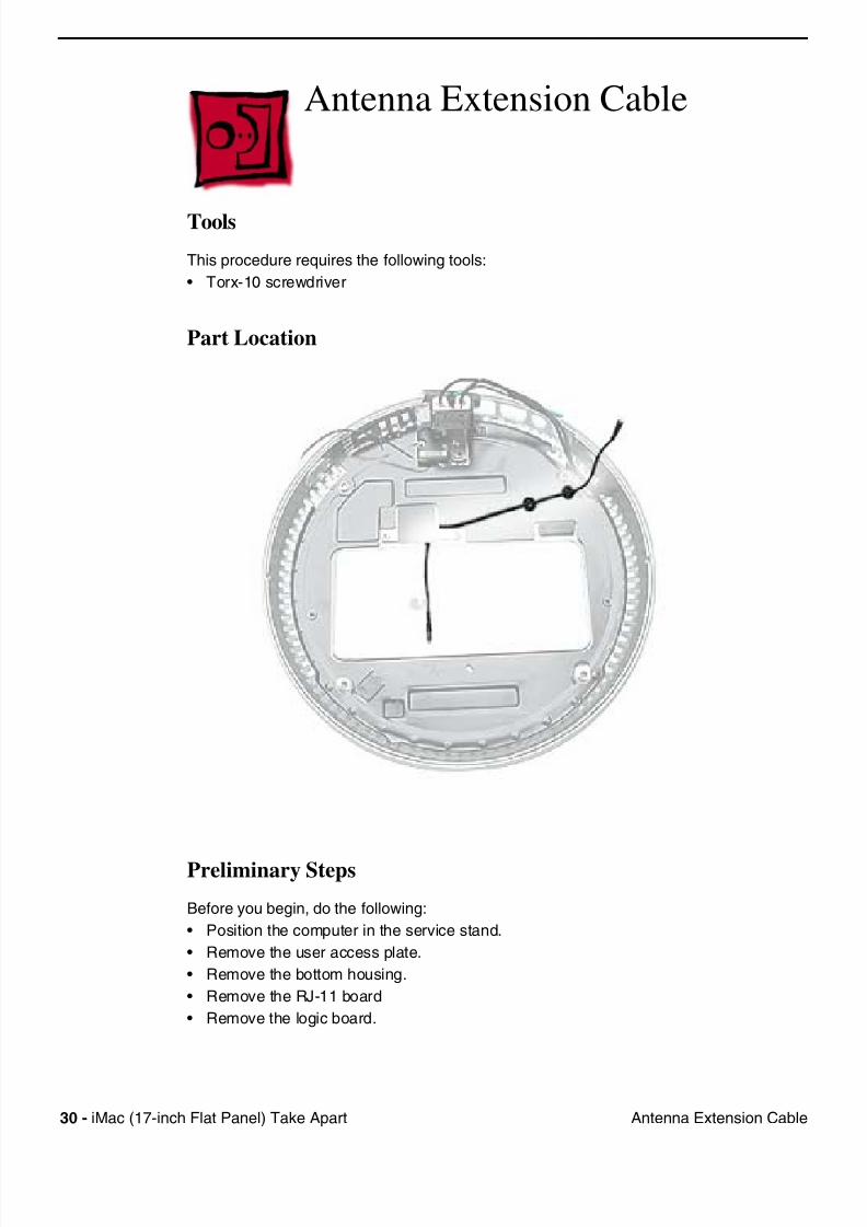
Antenna Extension Cable
Tools
This procedure requires the following tools:
• Torx-10 screwdriver
Part Location
Preliminary Steps
Before you begin, do the following:
• Position the computer in the service stand.
• Remove the user access plate.
• Remove the bottom housing.
• Remove the RJ-11 board
• Remove the logic board.
7/28/2019 iMAc 17inc
http://slidepdf.com/reader/full/imac-17inc 33/156
iM (17 i h Fl t P l) T k A t 31A t E t i C bl
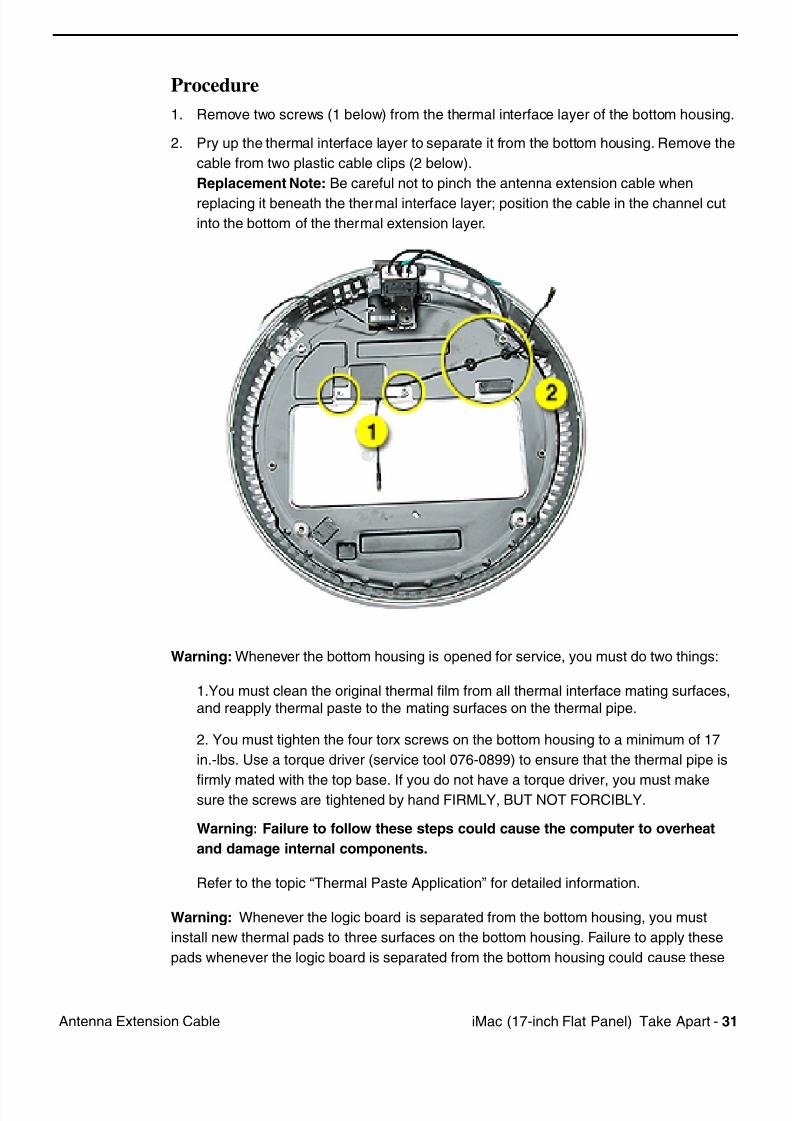
Procedure
1. Remove two screws (1 below) from the thermal interface layer of the bottom housing.
2. Pry up the thermal interface layer to separate it from the bottom housing. Remove the
cable from two plastic cable clips (2 below).
Replacement Note: Be careful not to pinch the antenna extension cable when
replacing it beneath the thermal interface layer; position the cable in the channel cut
into the bottom of the thermal extension layer.
Warning: Whenever the bottom housing is opened for service, you must do two things:
1.You must clean the original thermal film from all thermal interface mating surfaces,
and reapply thermal paste to the mating surfaces on the thermal pipe.
2. You must tighten the four torx screws on the bottom housing to a minimum of 17
in.-lbs. Use a torque driver (service tool 076-0899) to ensure that the thermal pipe is
firmly mated with the top base. If you do not have a torque driver, you must makesure the screws are tightened by hand FIRMLY, BUT NOT FORCIBLY.
Warning: Failure to follow these steps could cause the computer to overheat
and damage internal components.
Refer to the topic “Thermal Paste Application” for detailed information.
Warning: Whenever the logic board is separated from the bottom housing, you must
install new thermal pads to three surfaces on the bottom housing. Failure to apply these
pads whenever the logic board is separated from the bottom housing could cause these

7/28/2019 iMAc 17inc
http://slidepdf.com/reader/full/imac-17inc 34/156
32 iM (17 i h Fl t P l) T k A t A t E t i C bl
parts to overheat and could damage internal components.
Note: AFTER installing new thermal pads, if you must briefly re-separate the logic board
from the housing, it is OK to retain the same, new pads as long as they are not handled
excessively. Refer to “Thermal Pad Installation” in this chapter for detailed information.
7/28/2019 iMAc 17inc
http://slidepdf.com/reader/full/imac-17inc 35/156
iM (17 i h Fl t P l) T k A t 33Th l P d I t ll ti
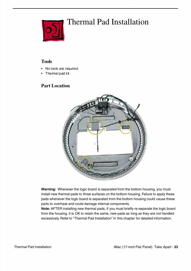
Thermal Pad Installation
Tools
• No tools are required.
• Thermal pad kit
Part Location
Warning: Whenever the logic board is separated from the bottom housing, you mustinstall new thermal pads to three surfaces on the bottom housing. Failure to apply these
pads whenever the logic board is separated from the bottom housing could cause these
parts to overheat and could damage internal components.
Note: AFTER installing new thermal pads, if you must briefly re-separate the logic board
from the housing, it is OK to retain the same, new pads as long as they are not handled
excessively. Refer to “Thermal Pad Installation” in this chapter for detailed information.
7/28/2019 iMAc 17inc
http://slidepdf.com/reader/full/imac-17inc 36/156
34 iM (17 i h Fl t P l) T k A t Th l P d I t ll ti
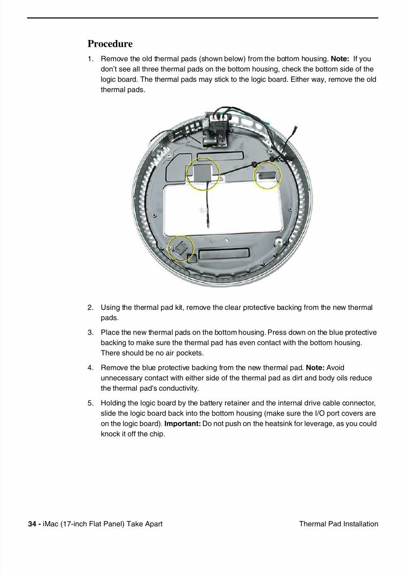
Procedure
1. Remove the old thermal pads (shown below) from the bottom housing. Note: If you
don’t see all three thermal pads on the bottom housing, check the bottom side of the
logic board. The thermal pads may stick to the logic board. Either way, remove the old
thermal pads.
2. Using the thermal pad kit, remove the clear protective backing from the new thermal
pads.
3. Place the new thermal pads on the bottom housing. Press down on the blue protective
backing to make sure the thermal pad has even contact with the bottom housing.
There should be no air pockets.
4. Remove the blue protective backing from the new thermal pad. Note: Avoid
unnecessary contact with either side of the thermal pad as dirt and body oils reduce
the thermal pad's conductivity.
5. Holding the logic board by the battery retainer and the internal drive cable connector,slide the logic board back into the bottom housing (make sure the I/O port covers are
on the logic board). Important: Do not push on the heatsink for leverage, as you could
knock it off the chip.
7/28/2019 iMAc 17inc
http://slidepdf.com/reader/full/imac-17inc 37/156
iM (17 i h Fl t P l) T k A t 35AC Li Filt
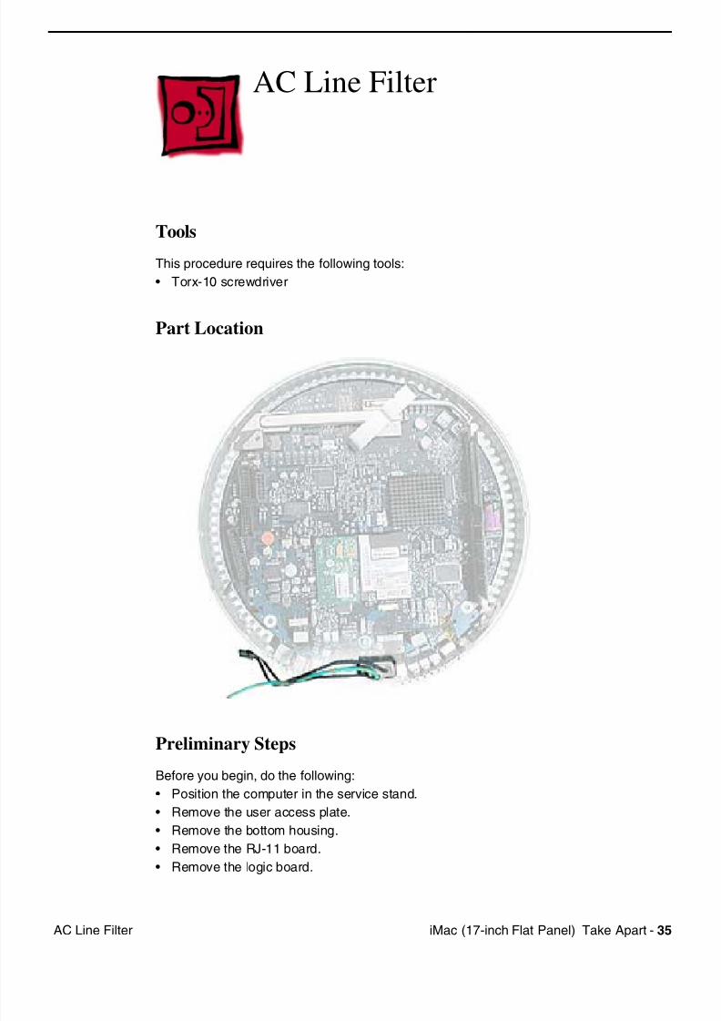
AC Line Filter
Tools
This procedure requires the following tools:
• Torx-10 screwdriver
Part Location
Preliminary Steps
Before you begin, do the following:
• Position the computer in the service stand.
• Remove the user access plate.
• Remove the bottom housing.
• Remove the RJ-11 board.
• Remove the logic board.
7/28/2019 iMAc 17inc
http://slidepdf.com/reader/full/imac-17inc 38/156
36 iM (17 i h Fl t P l) T k A t AC Li Filt
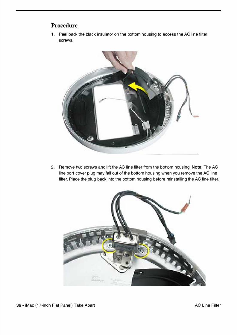
Procedure
1. Peel back the black insulator on the bottom housing to access the AC line filter
screws.
2. Remove two screws and lift the AC line filter from the bottom housing. Note: The AC
line port cover plug may fall out of the bottom housing when you remove the AC line
filter. Place the plug back into the bottom housing before reinstalling the AC line filter.
7/28/2019 iMAc 17inc
http://slidepdf.com/reader/full/imac-17inc 39/156
iM (17 i h Fl t P l) T k A t 37AC Li Filt
Warning: Whenever the bottom housing is opened for service, you must do two things:
1.You must clean the original thermal film from all thermal interface mating surfaces,
and reapply thermal paste to the mating surfaces on the thermal pipe.
2. You must tighten the four torx screws on the bottom housing to a minimum of 17
in.-lbs. Use a torque driver (service tool 076-0899) to ensure that the thermal pipe is
firmly mated with the top base. If you do not have a torque driver, you must make
sure the screws are tightened by hand FIRMLY, BUT NOT FORCIBLY.
Warning: Failure to follow these steps could cause the computer to overheat
and damage internal components.
Refer to the topic “Thermal Paste Application” for detailed information.
Warning: Whenever the logic board is separated from the bottom housing, you must
install new thermal pads to three surfaces on the bottom housing. Failure to apply these
pads whenever the logic board is separated from the bottom housing could cause these
parts to overheat and could damage internal components.
Note: AFTER installing new thermal pads, if you must briefly re-separate the logic board
from the housing, it is OK to retain the same, new pads as long as they are not handled
excessively. Refer to “Thermal Pad Installation” in this chapter for detailed information.
7/28/2019 iMAc 17inc
http://slidepdf.com/reader/full/imac-17inc 40/156
38 iM (17 i h Fl t P l) T k A t D i C i A bl (O ti l d H d D i )
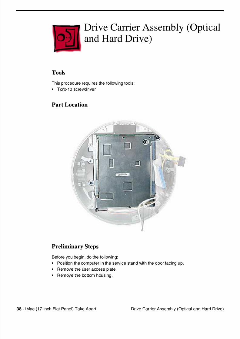
Drive Carrier Assembly (Opticaland Hard Drive)
Tools
This procedure requires the following tools:
• Torx-10 screwdriver
Part Location
Preliminary Steps
Before you begin, do the following:
• Position the computer in the service stand with the door facing up.
• Remove the user access plate.
• Remove the bottom housing.
7/28/2019 iMAc 17inc
http://slidepdf.com/reader/full/imac-17inc 41/156
iM (17 i h Fl t P l) T k A t 39D i C i A bl (O ti l d H d D i )
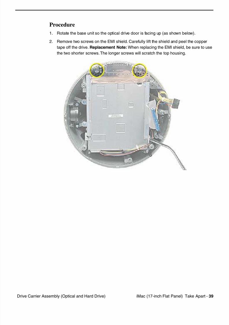
Procedure
1. Rotate the base unit so the optical drive door is facing up (as shown below).
2. Remove two screws on the EMI shield. Carefully lift the shield and peel the copper
tape off the drive. Replacement Note: When replacing the EMI shield, be sure to use
the two shorter screws. The longer screws will scratch the top housing.
7/28/2019 iMAc 17inc
http://slidepdf.com/reader/full/imac-17inc 42/156
40 iM (17 i h Fl t P l) T k A t D i C i A bl (O ti l d H d D i )
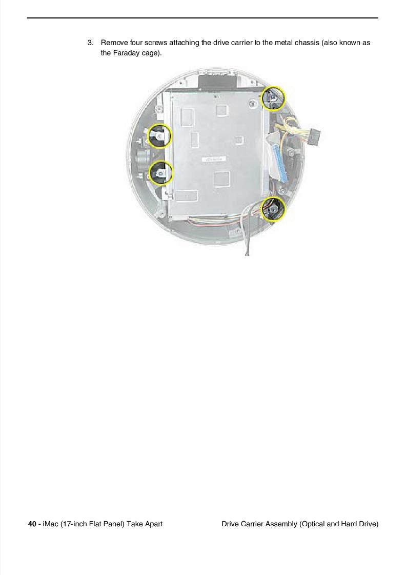
3. Remove four screws attaching the drive carrier to the metal chassis (also known as
the Faraday cage).
7/28/2019 iMAc 17inc
http://slidepdf.com/reader/full/imac-17inc 43/156
iM (17 i h Fl t P l) T k A t 41D i C i A bl (O ti l d H d D i )
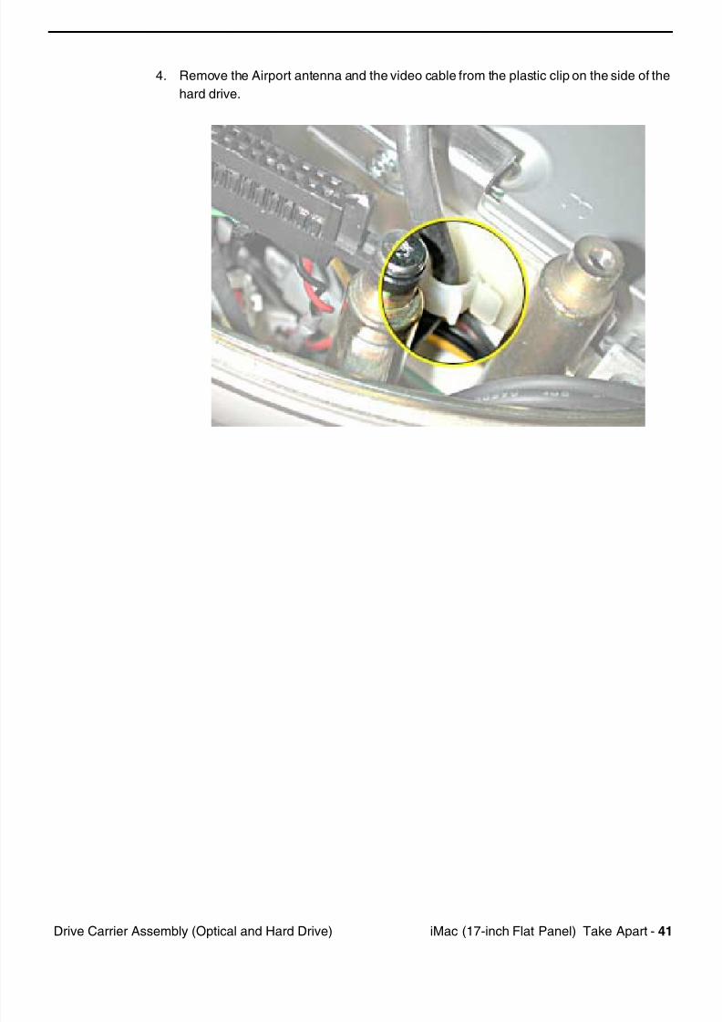
4. Remove the Airport antenna and the video cable from the plastic clip on the side of the
hard drive.
7/28/2019 iMAc 17inc
http://slidepdf.com/reader/full/imac-17inc 44/156
42 iM (17 i h Fl t P l) T k A t D i C i A bl (O ti l d H d D i )
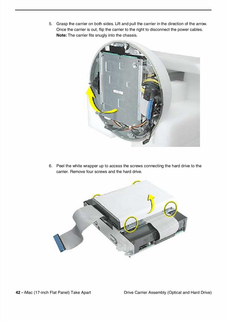
5. Grasp the carrier on both sides. Lift and pull the carrier in the direction of the arrow.
Once the carrier is out, flip the carrier to the right to disconnect the power cables.
Note: The carrier fits snugly into the chassis.
6. Peel the white wrapper up to access the screws connecting the hard drive to the
carrier. Remove four screws and the hard drive.
7/28/2019 iMAc 17inc
http://slidepdf.com/reader/full/imac-17inc 45/156
iM (17 i h Fl t P l) T k A t 43D i C i A bl (O ti l d H d D i )
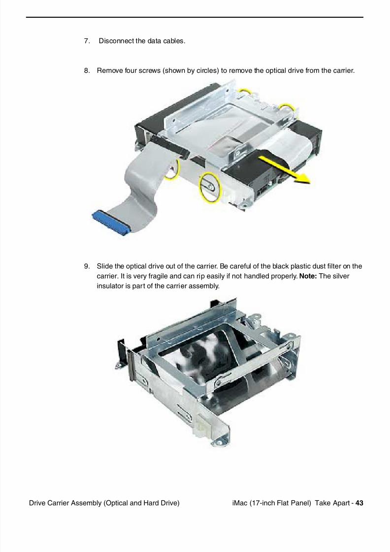
7. Disconnect the data cables.
8. Remove four screws (shown by circles) to remove the optical drive from the carrier.
9. Slide the optical drive out of the carrier. Be careful of the black plastic dust filter on the
carrier. It is very fragile and can rip easily if not handled properly. Note: The silver
insulator is part of the carrier assembly.

7/28/2019 iMAc 17inc
http://slidepdf.com/reader/full/imac-17inc 46/156
44 iM (17 i h Fl t P l) T k A t
Warning: Whenever the bottom housing is opened for service, you must do two things:
1.You must clean the original thermal film from all thermal interface mating surfaces,
and reapply thermal paste to the mating surfaces on the thermal pipe.
2. You must tighten the four torx screws on the bottom housing to a minimum of 17
in.-lbs. Use a torque driver (service tool 076-0899) to ensure that the thermal pipe is
firmly mated with the top base. If you do not have a torque driver, you must make
sure the screws are tightened by hand FIRMLY, BUT NOT FORCIBLY.
Warning: Failure to follow these steps could cause the computer to overheat
and damage internal components.
Refer to the topic “Thermal Paste Application” for detailed information.
7/28/2019 iMAc 17inc
http://slidepdf.com/reader/full/imac-17inc 47/156
iM (17 i h Fl t P l) T k A t 45P S l
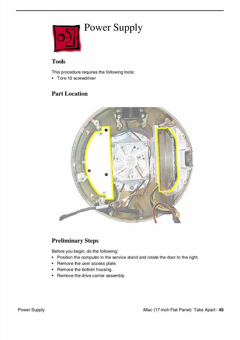
Power Supply
Tools
This procedure requires the following tools:
• Torx-10 screwdriver
Part Location
Preliminary Steps
Before you begin, do the following:
• Position the computer in the service stand and rotate the door to the right.
• Remove the user access plate.
• Remove the bottom housing.
• Remove the drive carrier assembly.
7/28/2019 iMAc 17inc
http://slidepdf.com/reader/full/imac-17inc 48/156
46 iM (17 i h Fl t P l) T k A t P S l
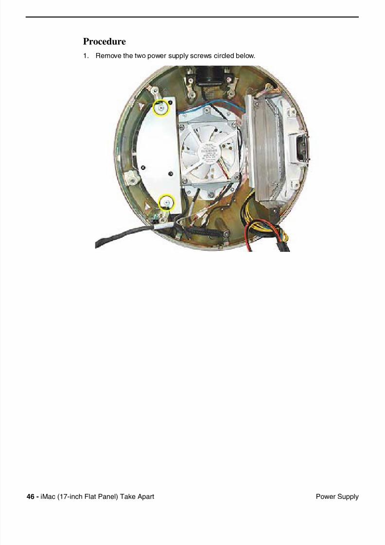
Procedure
1. Remove the two power supply screws circled below.
7/28/2019 iMAc 17inc
http://slidepdf.com/reader/full/imac-17inc 49/156
iM (17 i h Fl t P l) T k A t 47P S l
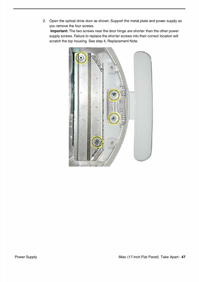
2. Open the optical drive door as shown. Support the metal plate and power supply as
you remove the four screws.
Important: The two screws near the door hinge are shorter than the other power
supply screws. Failure to replace the shorter screws into their correct location will
scratch the top housing. See step 4, Replacement Note.
7/28/2019 iMAc 17inc
http://slidepdf.com/reader/full/imac-17inc 50/156
48
iM (17 i h Fl t P l) T k A t P S l
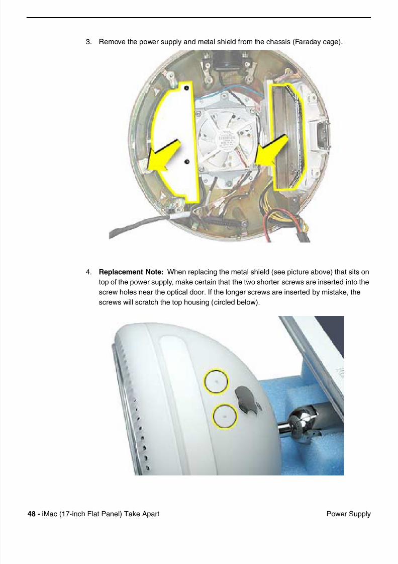
3. Remove the power supply and metal shield from the chassis (Faraday cage).
4.
Replacement Note:
When replacing the metal shield (see picture above) that sits on
top of the power supply, make certain that the two shorter screws are inserted into the
screw holes near the optical door. If the longer screws are inserted by mistake, the
screws will scratch the top housing (circled below).

7/28/2019 iMAc 17inc
http://slidepdf.com/reader/full/imac-17inc 51/156
iM (17 i h Fl t P l) T k A t 49
P S l
Warning:
Whenever the bottom housing is opened for service, you must do two things:
1.You must clean the original thermal film from all thermal interface mating surfaces,
and reapply thermal paste to the mating surfaces on the thermal pipe.
2. You must tighten the four torx screws on the bottom housing to a minimum of 17
in.-lbs. Use a torque driver (service tool 076-0899) to ensure that the thermal pipe is
firmly mated with the top base. If you do not have a torque driver, you must make
sure the screws are tightened by hand FIRMLY, BUT NOT FORCIBLY.
Warning:
Failure to follow these steps could cause the computer to overheat
and damage internal components.
Refer to the topic “Thermal Paste Application” for detailed information.
7/28/2019 iMAc 17inc
http://slidepdf.com/reader/full/imac-17inc 52/156
50
iM (17 i h Fl t P l) T k A t O ti l D i D
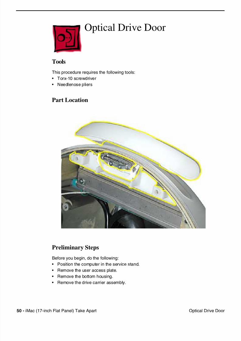
Optical Drive Door
Tools
This procedure requires the following tools:
• Torx-10 screwdriver
• Needlenose pliers
Part Location
Preliminary Steps
Before you begin, do the following:
• Position the computer in the service stand.
• Remove the user access plate.
• Remove the bottom housing.
• Remove the drive carrier assembly.
7/28/2019 iMAc 17inc
http://slidepdf.com/reader/full/imac-17inc 53/156
iM (17 i h Fl t P l) T k A t 51
O ti l D i D
Procedure
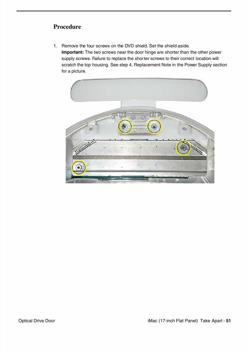
1. Remove the four screws on the DVD shield. Set the shield aside.
Important:
The two screws near the door hinge are shorter than the other power
supply screws. Failure to replace the shorter screws to their correct location will
scratch the top housing. See step 4, Replacement Note in the Power Supply section
for a picture.
7/28/2019 iMAc 17inc
http://slidepdf.com/reader/full/imac-17inc 54/156
52
iM (17 i h Fl t P l) T k A t O ti l D i D
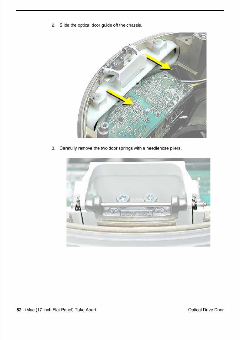
2. Slide the optical door guide off the chassis.
3. Carefully remove the two door springs with a needlenose pliers.
7/28/2019 iMAc 17inc
http://slidepdf.com/reader/full/imac-17inc 55/156
iM (17 i h Fl t P l) T k A t 53O ti l D i D
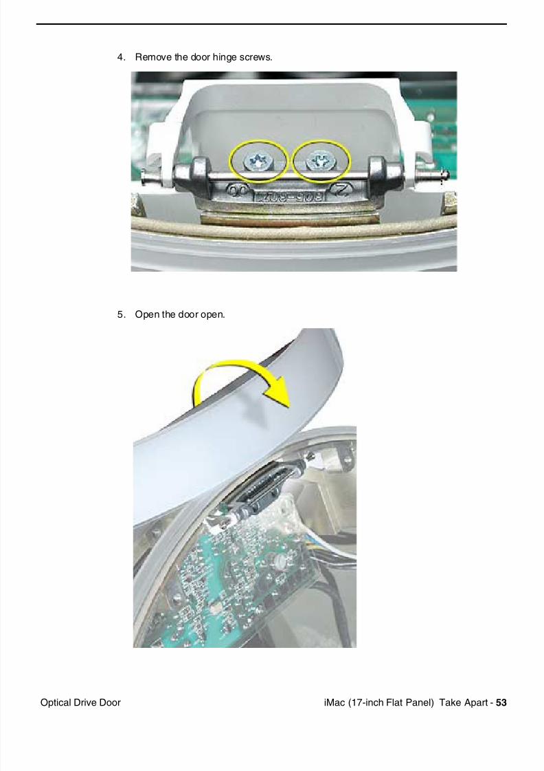
4. Remove the door hinge screws.
5. Open the door open.
7/28/2019 iMAc 17inc
http://slidepdf.com/reader/full/imac-17inc 56/156
54 iM (17 i h Fl t P l) T k A t O ti l D i D
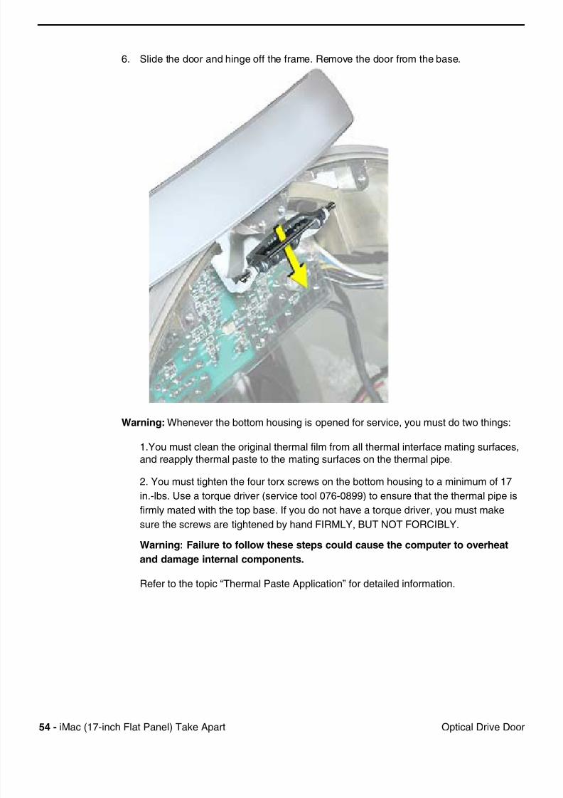
6. Slide the door and hinge off the frame. Remove the door from the base.
Warning: Whenever the bottom housing is opened for service, you must do two things:
1.You must clean the original thermal film from all thermal interface mating surfaces,
and reapply thermal paste to the mating surfaces on the thermal pipe.
2. You must tighten the four torx screws on the bottom housing to a minimum of 17
in.-lbs. Use a torque driver (service tool 076-0899) to ensure that the thermal pipe is
firmly mated with the top base. If you do not have a torque driver, you must make
sure the screws are tightened by hand FIRMLY, BUT NOT FORCIBLY.
Warning: Failure to follow these steps could cause the computer to overheat
and damage internal components.
Refer to the topic “Thermal Paste Application” for detailed information.
7/28/2019 iMAc 17inc
http://slidepdf.com/reader/full/imac-17inc 57/156
iM (17 i h Fl t P l) T k A t 55S k I t l
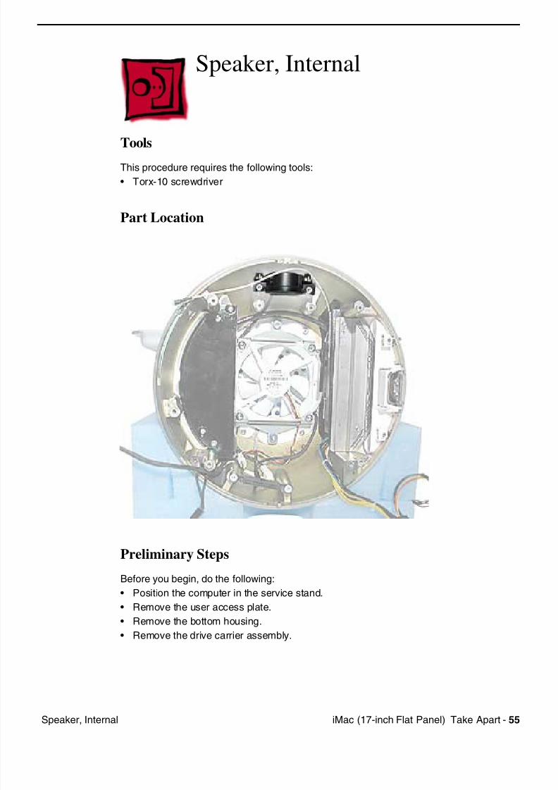
Speaker, Internal
Tools
This procedure requires the following tools:
• Torx-10 screwdriver
Part Location
Preliminary Steps
Before you begin, do the following:
• Position the computer in the service stand.
• Remove the user access plate.
• Remove the bottom housing.
• Remove the drive carrier assembly.
7/28/2019 iMAc 17inc
http://slidepdf.com/reader/full/imac-17inc 58/156
56 iM (17 i h Fl t P l) T k A t S k I t l
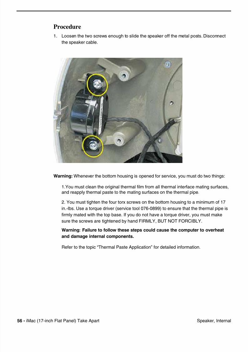
Procedure
1. Loosen the two screws enough to slide the speaker off the metal posts. Disconnect
the speaker cable.
Warning: Whenever the bottom housing is opened for service, you must do two things:
1.You must clean the original thermal film from all thermal interface mating surfaces,and reapply thermal paste to the mating surfaces on the thermal pipe.
2. You must tighten the four torx screws on the bottom housing to a minimum of 17
in.-lbs. Use a torque driver (service tool 076-0899) to ensure that the thermal pipe is
firmly mated with the top base. If you do not have a torque driver, you must make
sure the screws are tightened by hand FIRMLY, BUT NOT FORCIBLY.
Warning: Failure to follow these steps could cause the computer to overheat
and damage internal components.
Refer to the topic “Thermal Paste Application” for detailed information.
7/28/2019 iMAc 17inc
http://slidepdf.com/reader/full/imac-17inc 59/156
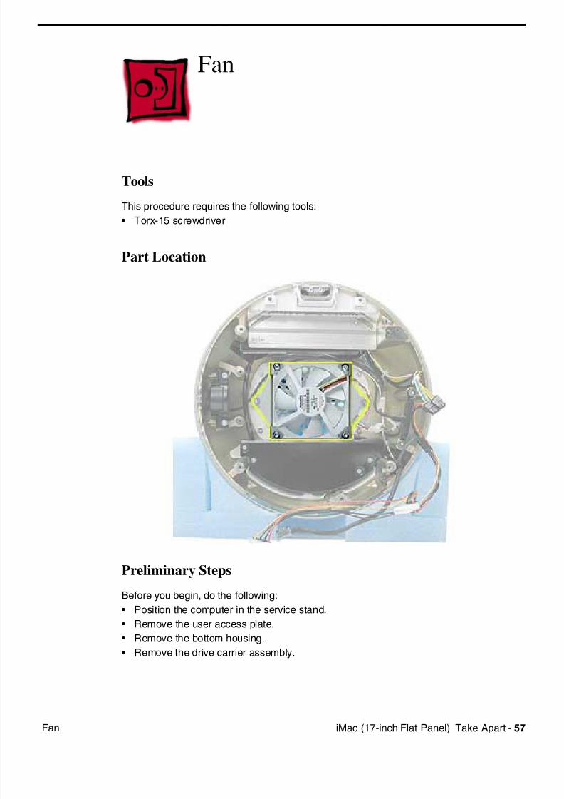
iM (17 i h Fl t P l) T k A t 57F
Fan
Tools
This procedure requires the following tools:
• Torx-15 screwdriver
Part Location
Preliminary Steps
Before you begin, do the following:
• Position the computer in the service stand.
• Remove the user access plate.
• Remove the bottom housing.
• Remove the drive carrier assembly.
7/28/2019 iMAc 17inc
http://slidepdf.com/reader/full/imac-17inc 60/156
58 iM (17 i h Fl t P l) T k A t F
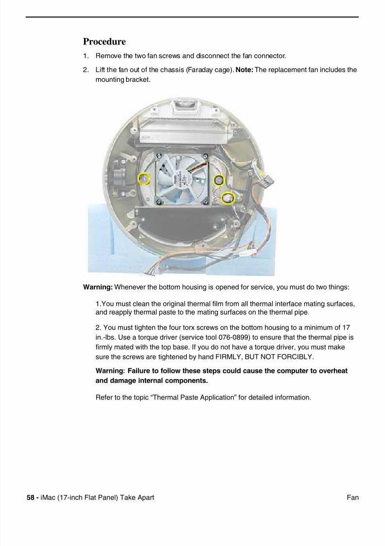
Procedure
1. Remove the two fan screws and disconnect the fan connector.
2. Lift the fan out of the chassis (Faraday cage). Note:The replacement fan includes the
mounting bracket.
Warning: Whenever the bottom housing is opened for service, you must do two things:
1.You must clean the original thermal film from all thermal interface mating surfaces,and reapply thermal paste to the mating surfaces on the thermal pipe.
2. You must tighten the four torx screws on the bottom housing to a minimum of 17
in.-lbs. Use a torque driver (service tool 076-0899) to ensure that the thermal pipe is
firmly mated with the top base. If you do not have a torque driver, you must make
sure the screws are tightened by hand FIRMLY, BUT NOT FORCIBLY.
Warning: Failure to follow these steps could cause the computer to overheat
and damage internal components.
Refer to the topic “Thermal Paste Application” for detailed information.
7/28/2019 iMAc 17inc
http://slidepdf.com/reader/full/imac-17inc 61/156
iM (17 i h Fl t P l) T k A t 59P S l I l t
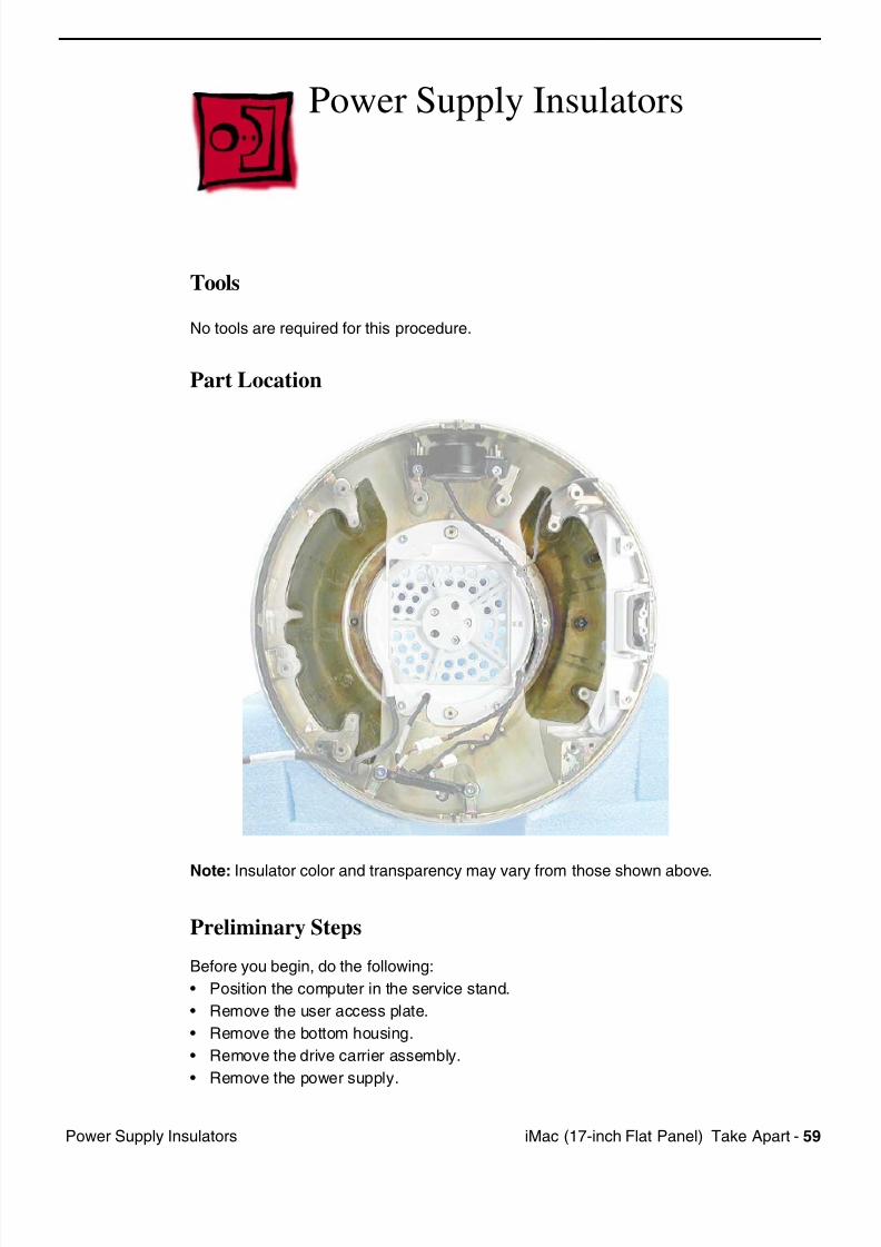
Power Supply Insulators
Tools
No tools are required for this procedure.
Part Location
Note: Insulator color and transparency may vary from those shown above.
Preliminary Steps
Before you begin, do the following:
• Position the computer in the service stand.
• Remove the user access plate.
• Remove the bottom housing.
• Remove the drive carrier assembly.
• Remove the power supply.
7/28/2019 iMAc 17inc
http://slidepdf.com/reader/full/imac-17inc 62/156
60 iM (17 i h Fl t P l) T k A t P S l I l t
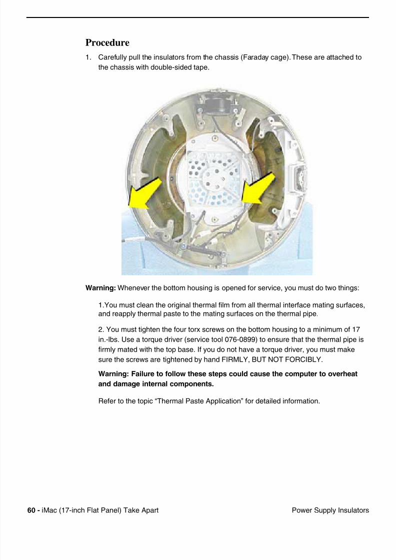
Procedure
1. Carefully pull the insulators from the chassis (Faraday cage). These are attached to
the chassis with double-sided tape.
Warning: Whenever the bottom housing is opened for service, you must do two things:
1.You must clean the original thermal film from all thermal interface mating surfaces,
and reapply thermal paste to the mating surfaces on the thermal pipe.
2. You must tighten the four torx screws on the bottom housing to a minimum of 17
in.-lbs. Use a torque driver (service tool 076-0899) to ensure that the thermal pipe is
firmly mated with the top base. If you do not have a torque driver, you must make
sure the screws are tightened by hand FIRMLY, BUT NOT FORCIBLY.
Warning: Failure to follow these steps could cause the computer to overheat
and damage internal components.
Refer to the topic “Thermal Paste Application” for detailed information.
7/28/2019 iMAc 17inc
http://slidepdf.com/reader/full/imac-17inc 63/156
iM (17 i h Fl t P l) T k A t 61F B k t ( d f )
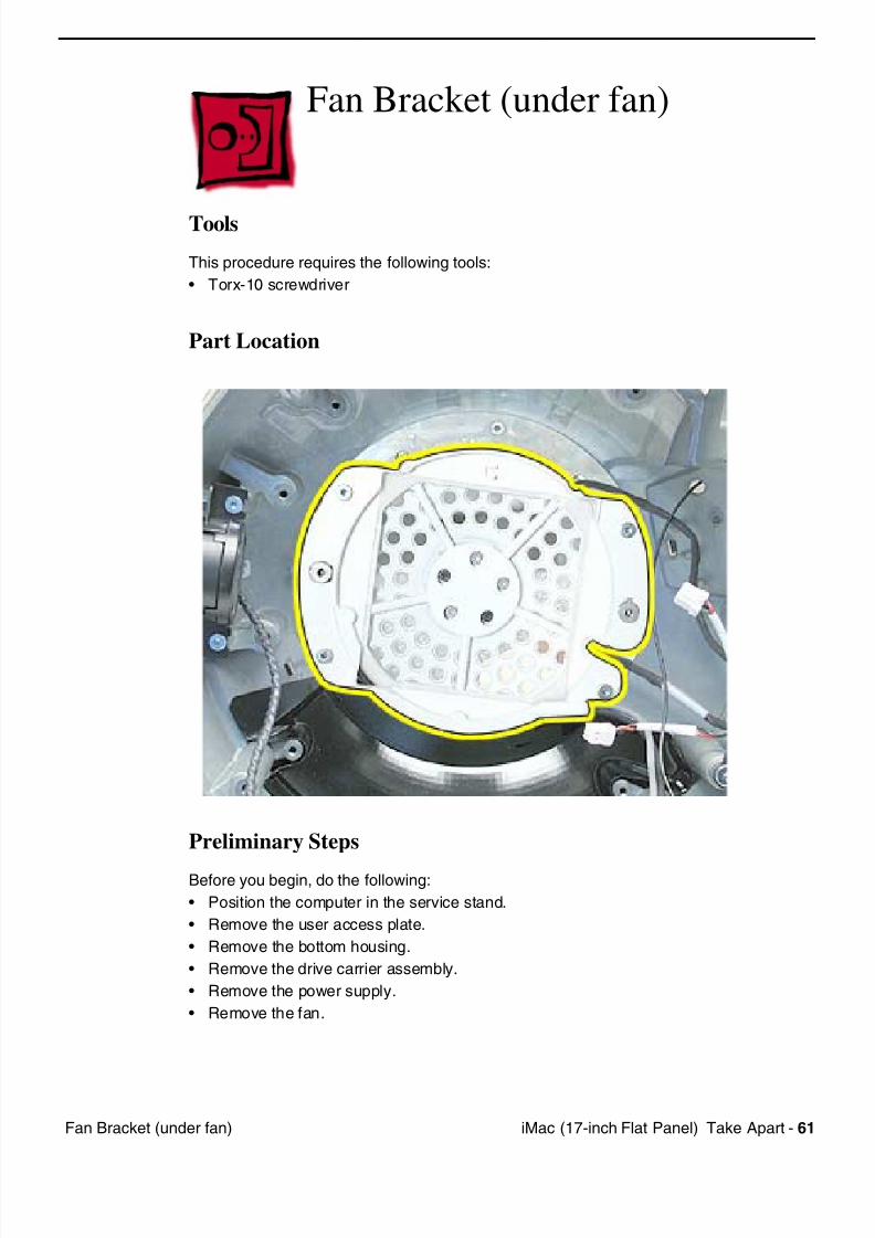
Fan Bracket (under fan)
Tools
This procedure requires the following tools:
• Torx-10 screwdriver
Part Location
Preliminary Steps
Before you begin, do the following:
• Position the computer in the service stand.
• Remove the user access plate.
• Remove the bottom housing.
• Remove the drive carrier assembly.
• Remove the power supply.
• Remove the fan.
7/28/2019 iMAc 17inc
http://slidepdf.com/reader/full/imac-17inc 64/156
62 iM (17 i h Fl t P l) T k A t F B k t ( d f )
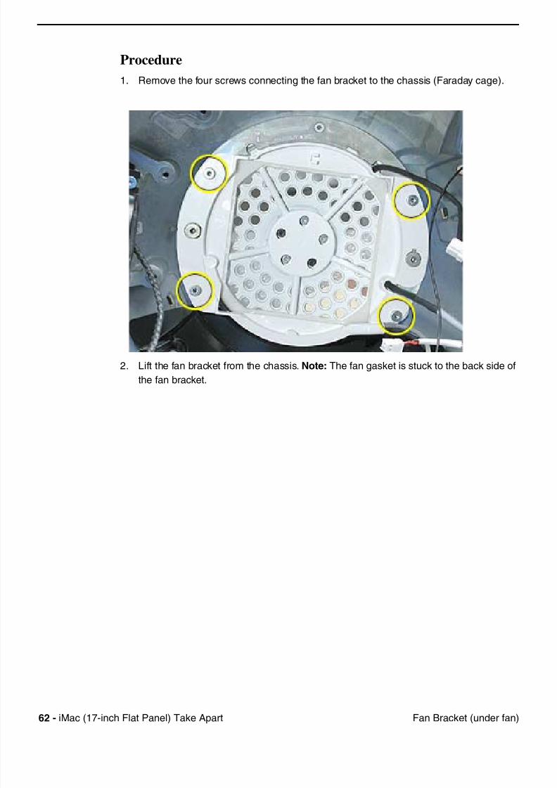
Procedure
1. Remove the four screws connecting the fan bracket to the chassis (Faraday cage).
2. Lift the fan bracket from the chassis. Note: The fan gasket is stuck to the back side of
the fan bracket.
7/28/2019 iMAc 17inc
http://slidepdf.com/reader/full/imac-17inc 65/156
iM (17 i h Fl t P l) T k A t 63F B k t ( d f )
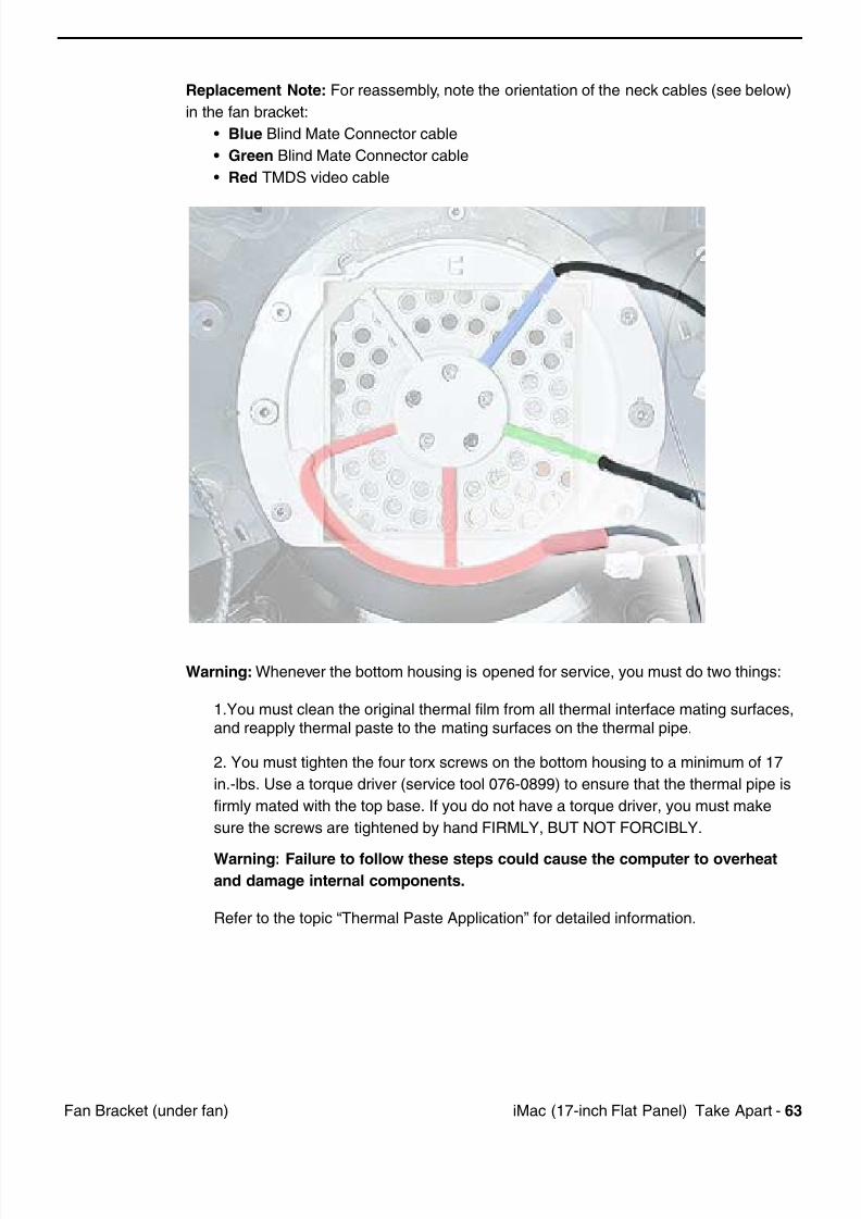
Replacement Note: For reassembly, note the orientation of the neck cables (see below)
in the fan bracket:
• Blue Blind Mate Connector cable
• Green Blind Mate Connector cable
• Red TMDS video cable
Warning: Whenever the bottom housing is opened for service, you must do two things:
1.You must clean the original thermal film from all thermal interface mating surfaces,and reapply thermal paste to the mating surfaces on the thermal pipe.
2. You must tighten the four torx screws on the bottom housing to a minimum of 17
in.-lbs. Use a torque driver (service tool 076-0899) to ensure that the thermal pipe is
firmly mated with the top base. If you do not have a torque driver, you must make
sure the screws are tightened by hand FIRMLY, BUT NOT FORCIBLY.
Warning: Failure to follow these steps could cause the computer to overheat
and damage internal components.
Refer to the topic “Thermal Paste Application” for detailed information.
7/28/2019 iMAc 17inc
http://slidepdf.com/reader/full/imac-17inc 66/156
64 iM (17 i h Fl t P l) T k A t F G k t
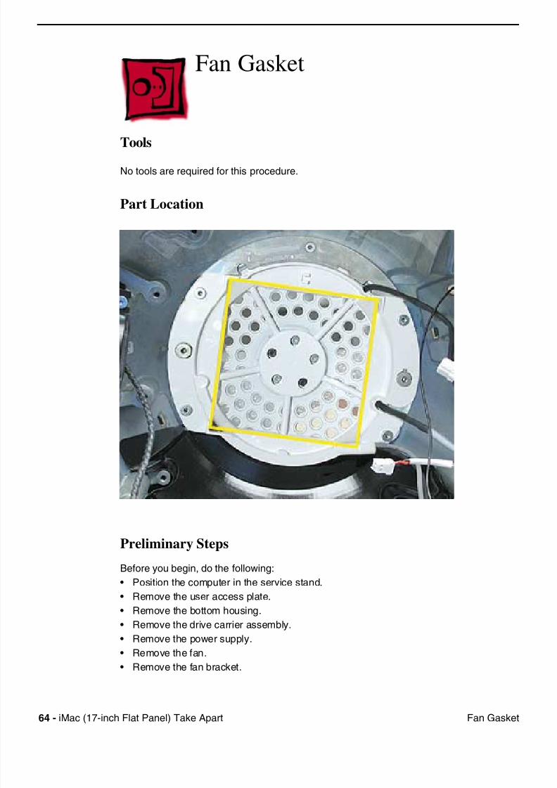
Fan Gasket
Tools
No tools are required for this procedure.
Part Location
Preliminary Steps
Before you begin, do the following:
• Position the computer in the service stand.
• Remove the user access plate.
• Remove the bottom housing.
• Remove the drive carrier assembly.
• Remove the power supply.
• Remove the fan.
• Remove the fan bracket.
7/28/2019 iMAc 17inc
http://slidepdf.com/reader/full/imac-17inc 67/156
iM (17 i h Fl t P l) T k A t 65F G k t
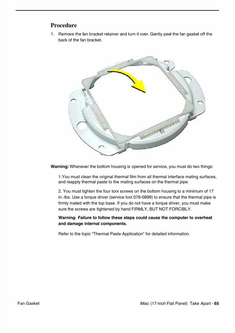
Procedure
1. Remove the fan bracket retainer and turn it over. Gently peel the fan gasket off the
back of the fan bracket.
Warning: Whenever the bottom housing is opened for service, you must do two things:
1.You must clean the original thermal film from all thermal interface mating surfaces,and reapply thermal paste to the mating surfaces on the thermal pipe.
2. You must tighten the four torx screws on the bottom housing to a minimum of 17
in.-lbs. Use a torque driver (service tool 076-0899) to ensure that the thermal pipe is
firmly mated with the top base. If you do not have a torque driver, you must make
sure the screws are tightened by hand FIRMLY, BUT NOT FORCIBLY.
Warning: Failure to follow these steps could cause the computer to overheat
and damage internal components.
Refer to the topic “Thermal Paste Application” for detailed information.
7/28/2019 iMAc 17inc
http://slidepdf.com/reader/full/imac-17inc 68/156
66 iM (17 i h Fl t P l) T k A t C N k S k R t i
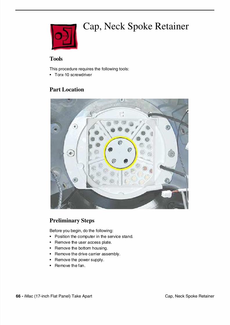
Cap, Neck Spoke Retainer
Tools
This procedure requires the following tools:
• Torx-10 screwdriver
Part Location
Preliminary Steps
Before you begin, do the following:
• Position the computer in the service stand.
• Remove the user access plate.
• Remove the bottom housing.
• Remove the drive carrier assembly.
• Remove the power supply.
• Remove the fan.
7/28/2019 iMAc 17inc
http://slidepdf.com/reader/full/imac-17inc 69/156
iM (17 i h Fl t P l) T k A t 67C N k S k R t i
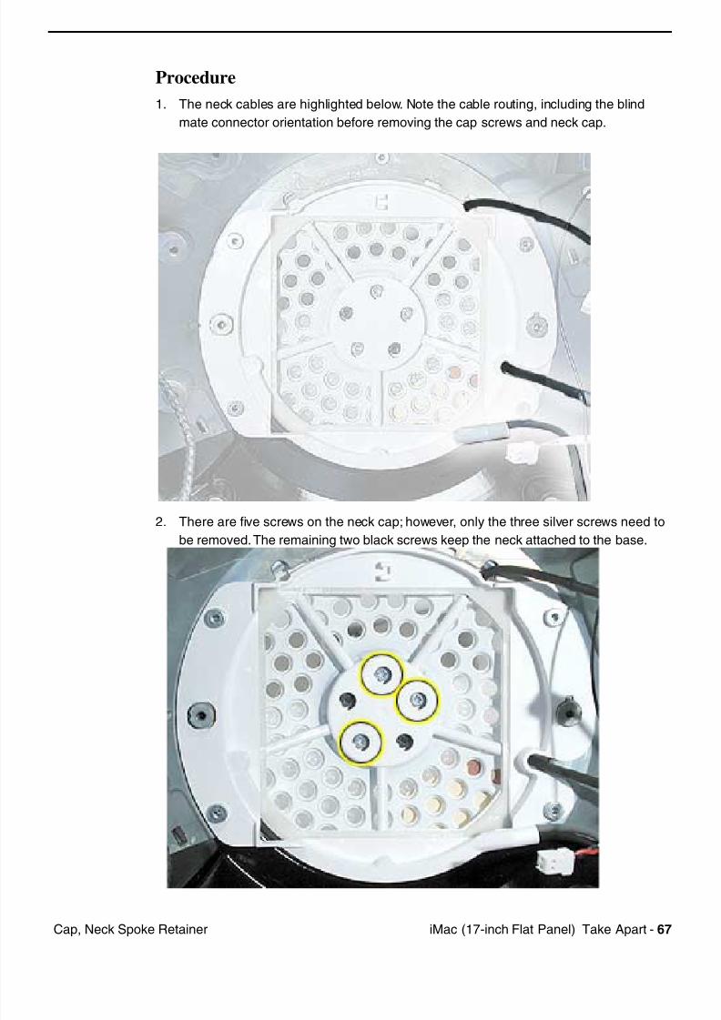
Procedure
1. The neck cables are highlighted below. Note the cable routing, including the blind
mate connector orientation before removing the cap screws and neck cap.
2. There are five screws on the neck cap; however, only the three silver screws need to
be removed. The remaining two black screws keep the neck attached to the base.
7/28/2019 iMAc 17inc
http://slidepdf.com/reader/full/imac-17inc 70/156
68 iM (17 i h Fl t P l) T k A t C N k S k R t i
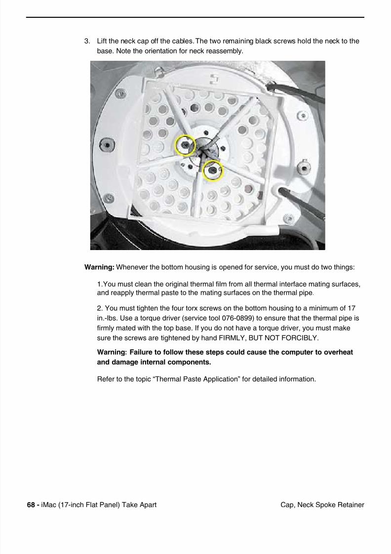
3. Lift the neck cap off the cables. The two remaining black screws hold the neck to the
base. Note the orientation for neck reassembly.
Warning: Whenever the bottom housing is opened for service, you must do two things:
1.You must clean the original thermal film from all thermal interface mating surfaces,
and reapply thermal paste to the mating surfaces on the thermal pipe.
2. You must tighten the four torx screws on the bottom housing to a minimum of 17
in.-lbs. Use a torque driver (service tool 076-0899) to ensure that the thermal pipe is
firmly mated with the top base. If you do not have a torque driver, you must make
sure the screws are tightened by hand FIRMLY, BUT NOT FORCIBLY.
Warning: Failure to follow these steps could cause the computer to overheat
and damage internal components.
Refer to the topic “Thermal Paste Application” for detailed information.
7/28/2019 iMAc 17inc
http://slidepdf.com/reader/full/imac-17inc 71/156
iM (17 i h Fl t P l) T k A t 69Bli d M t C t
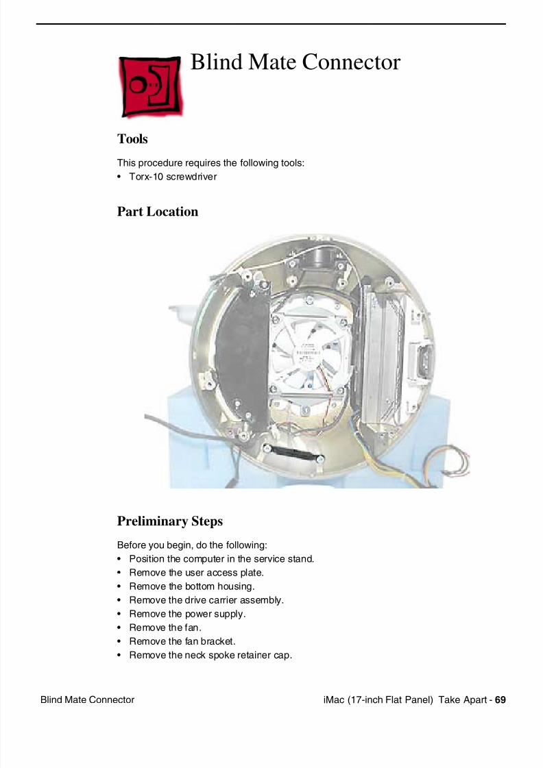
Blind Mate Connector
Tools
This procedure requires the following tools:
• Torx-10 screwdriver
Part Location
Preliminary Steps
Before you begin, do the following:
• Position the computer in the service stand.
• Remove the user access plate.
• Remove the bottom housing.
• Remove the drive carrier assembly.
• Remove the power supply.
• Remove the fan.
• Remove the fan bracket.
• Remove the neck spoke retainer cap.
7/28/2019 iMAc 17inc
http://slidepdf.com/reader/full/imac-17inc 72/156
70 iM (17 i h Fl t P l) T k A t Bli d M t C t
Procedure
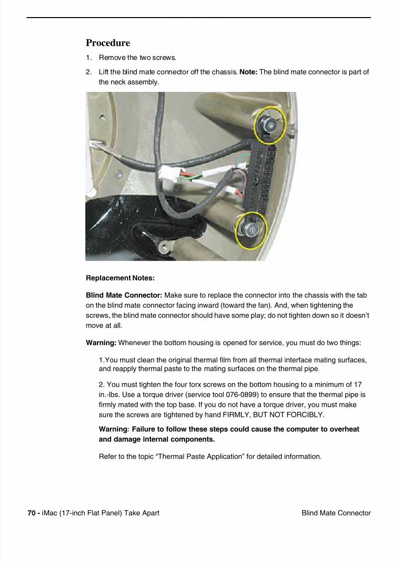
1. Remove the two screws.
2. Lift the blind mate connector off the chassis. Note: The blind mate connector is part of
the neck assembly.
Replacement Notes:
Blind Mate Connector: Make sure to replace the connector into the chassis with the tabon the blind mate connector facing inward (toward the fan). And, when tightening the
screws, the blind mate connector should have some play; do not tighten down so it doesn’t
move at all.
Warning: Whenever the bottom housing is opened for service, you must do two things:
1.You must clean the original thermal film from all thermal interface mating surfaces,
and reapply thermal paste to the mating surfaces on the thermal pipe.
2. You must tighten the four torx screws on the bottom housing to a minimum of 17
in.-lbs. Use a torque driver (service tool 076-0899) to ensure that the thermal pipe isfirmly mated with the top base. If you do not have a torque driver, you must make
sure the screws are tightened by hand FIRMLY, BUT NOT FORCIBLY.
Warning: Failure to follow these steps could cause the computer to overheat
and damage internal components.
Refer to the topic “Thermal Paste Application” for detailed information.
7/28/2019 iMAc 17inc
http://slidepdf.com/reader/full/imac-17inc 73/156
iM (17 i h Fl t P l) T k A t 71Ch i (F d C )
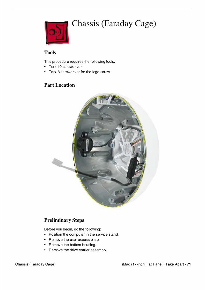
Chassis (Faraday Cage)
Tools
This procedure requires the following tools:
• Torx-10 screwdriver
• Torx-8 screwdriver for the logo screw
Part Location
Preliminary Steps
Before you begin, do the following:
• Position the computer in the service stand.
• Remove the user access plate.
• Remove the bottom housing.
• Remove the drive carrier assembly.
7/28/2019 iMAc 17inc
http://slidepdf.com/reader/full/imac-17inc 74/156
72 iM (17 i h Fl t P l) T k A t Ch i (F d C )
• Remove the power supply.
• Remove the fan.
• Remove the plastic cable retainer (under the fan).
• Remove the neck spoke retainer cap.
• Remove the blind mate connector screws.
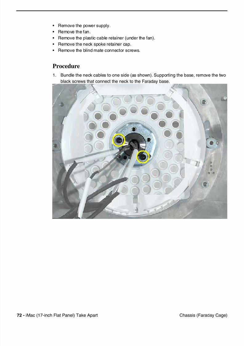
Procedure
1. Bundle the neck cables to one side (as shown). Supporting the base, remove the two
black screws that connect the neck to the Faraday base.
7/28/2019 iMAc 17inc
http://slidepdf.com/reader/full/imac-17inc 75/156
iM (17 i h Fl t P l) T k A t 73Ch i (F d C )
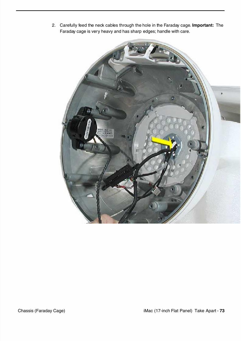
2. Carefully feed the neck cables through the hole in the Faraday cage. Important: The
Faraday cage is very heavy and has sharp edges; handle with care.
7/28/2019 iMAc 17inc
http://slidepdf.com/reader/full/imac-17inc 76/156
74 iM (17 i h Fl t P l) T k A t Ch i (F d C )
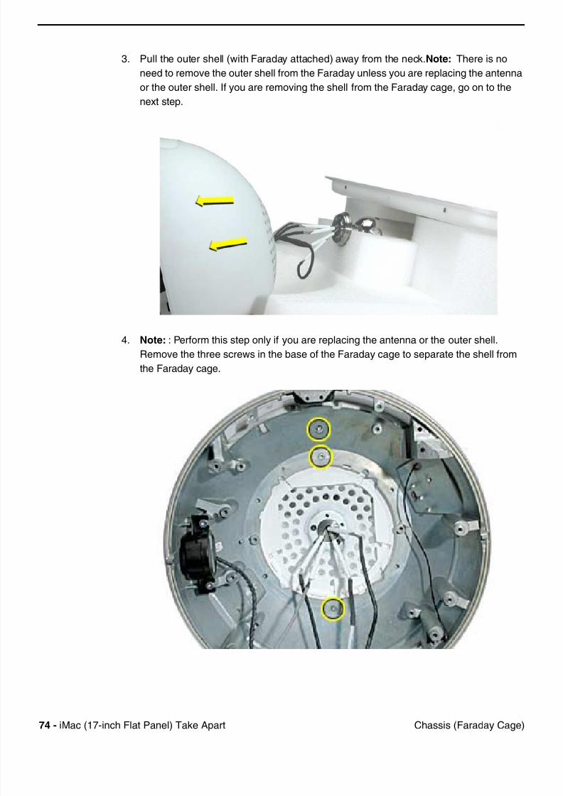
3. Pull the outer shell (with Faraday attached) away from the neck.Note: There is no
need to remove the outer shell from the Faraday unless you are replacing the antenna
or the outer shell. If you are removing the shell from the Faraday cage, go on to the
next step.
4. Note: : Perform this step only if you are replacing the antenna or the outer shell.
Remove the three screws in the base of the Faraday cage to separate the shell from
the Faraday cage.
7/28/2019 iMAc 17inc
http://slidepdf.com/reader/full/imac-17inc 77/156
iM (17 i h Fl t P l) T k A t 75Ch i (F d C )
Replacement Notes:
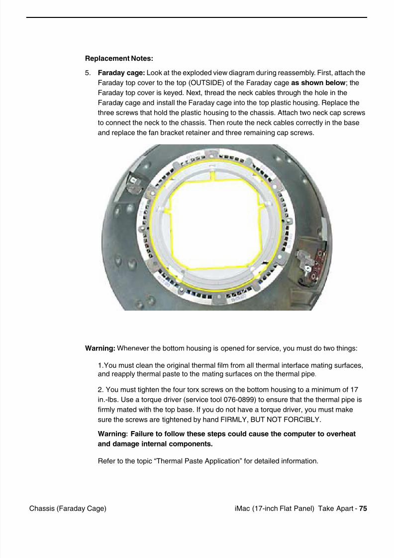
5. Faraday cage: Look at the exploded view diagram during reassembly. First, attach the
Faraday top cover to the top (OUTSIDE) of the Faraday cage as shown below; the
Faraday top cover is keyed. Next, thread the neck cables through the hole in the
Faraday cage and install the Faraday cage into the top plastic housing. Replace the
three screws that hold the plastic housing to the chassis. Attach two neck cap screws
to connect the neck to the chassis. Then route the neck cables correctly in the base
and replace the fan bracket retainer and three remaining cap screws.
Warning: Whenever the bottom housing is opened for service, you must do two things:
1.You must clean the original thermal film from all thermal interface mating surfaces,and reapply thermal paste to the mating surfaces on the thermal pipe.
2. You must tighten the four torx screws on the bottom housing to a minimum of 17in.-lbs. Use a torque driver (service tool 076-0899) to ensure that the thermal pipe is
firmly mated with the top base. If you do not have a torque driver, you must make
sure the screws are tightened by hand FIRMLY, BUT NOT FORCIBLY.
Warning: Failure to follow these steps could cause the computer to overheat
and damage internal components.
Refer to the topic “Thermal Paste Application” for detailed information.
7/28/2019 iMAc 17inc
http://slidepdf.com/reader/full/imac-17inc 78/156
76 iM (17 i h Fl t P l) T k A t Ai P t A t
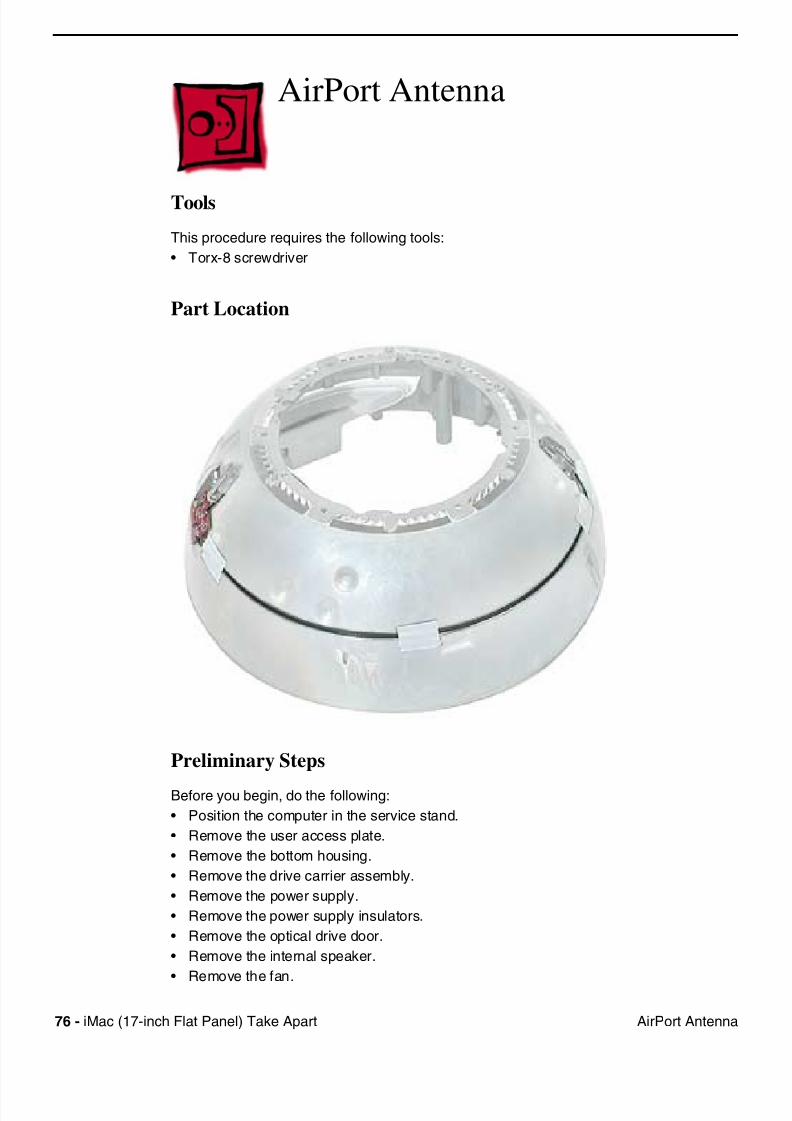
AirPort Antenna
Tools
This procedure requires the following tools:
• Torx-8 screwdriver
Part Location
Preliminary Steps
Before you begin, do the following:
• Position the computer in the service stand.
• Remove the user access plate.
• Remove the bottom housing.
• Remove the drive carrier assembly.
• Remove the power supply.
• Remove the power supply insulators.
• Remove the optical drive door.
• Remove the internal speaker.
• Remove the fan.
7/28/2019 iMAc 17inc
http://slidepdf.com/reader/full/imac-17inc 79/156
iM (17 i h Fl t P l) T k A t 77Ai P t A t
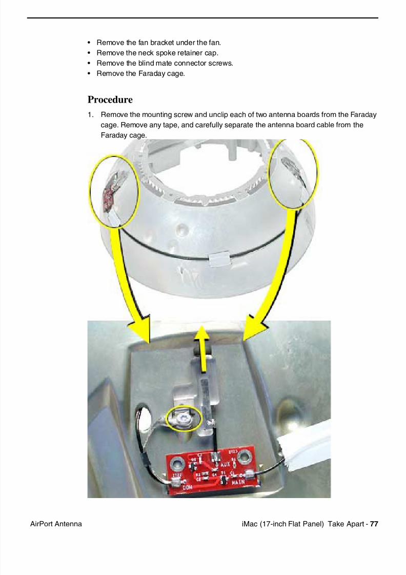
• Remove the fan bracket under the fan.
• Remove the neck spoke retainer cap.
• Remove the blind mate connector screws.
• Remove the Faraday cage.
Procedure1. Remove the mounting screw and unclip each of two antenna boards from the Faraday
cage. Remove any tape, and carefully separate the antenna board cable from the
Faraday cage.

7/28/2019 iMAc 17inc
http://slidepdf.com/reader/full/imac-17inc 80/156
78 iM (17 i h Fl t P l) T k A t Ai P t A t
Warning: Whenever the bottom housing is opened for service, you must do two things:
1.You must clean the original thermal film from all thermal interface mating surfaces,
and reapply thermal paste to the mating surfaces on the thermal pipe.
2. You must tighten the four torx screws on the bottom housing to a minimum of 17
in.-lbs. Use a torque driver (service tool 076-0899) to ensure that the thermal pipe is
firmly mated with the top base. If you do not have a torque driver, you must make
sure the screws are tightened by hand FIRMLY, BUT NOT FORCIBLY.
Warning: Failure to follow these steps could cause the computer to overheat
and damage internal components.
Refer to the topic “Thermal Paste Application” for detailed information.
7/28/2019 iMAc 17inc
http://slidepdf.com/reader/full/imac-17inc 81/156
iM (17 i h Fl t P l) T k A t 79H i O t Sh ll Pl ti
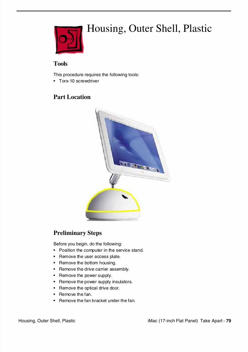
Housing, Outer Shell, Plastic
Tools
This procedure requires the following tools:
• Torx-10 screwdriver
Part Location
Preliminary Steps
Before you begin, do the following:
• Position the computer in the service stand.
• Remove the user access plate.
• Remove the bottom housing.
• Remove the drive carrier assembly.
• Remove the power supply.
• Remove the power supply insulators.
• Remove the optical drive door.
• Remove the fan.
• Remove the fan bracket under the fan.

7/28/2019 iMAc 17inc
http://slidepdf.com/reader/full/imac-17inc 82/156
80 iM (17 i h Fl t P l) T k A t H i O t Sh ll Pl ti
• Remove the neck spoke retainer cap.
• Remove the blind mate connector screws.
7/28/2019 iMAc 17inc
http://slidepdf.com/reader/full/imac-17inc 83/156
iM (17 i h Fl t P l) T k A t 81H i O t Sh ll Pl ti
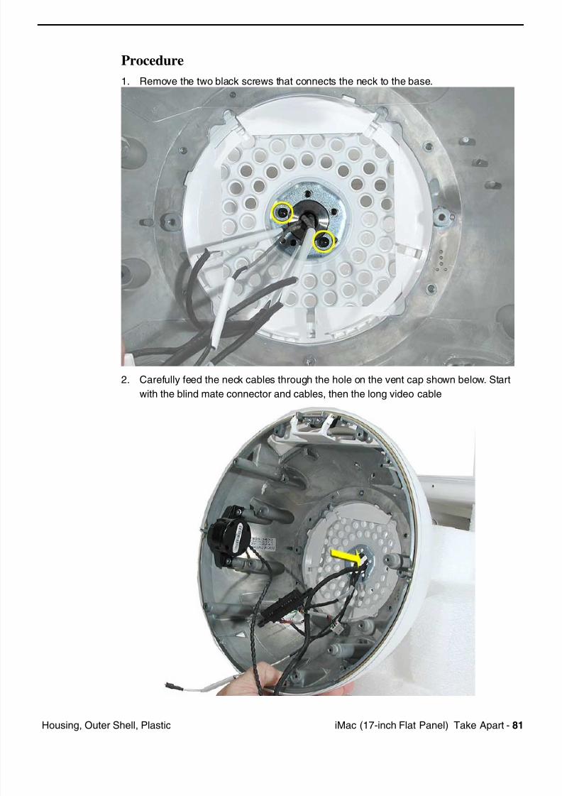
Procedure
1. Remove the two black screws that connects the neck to the base.
2. Carefully feed the neck cables through the hole on the vent cap shown below. Start
with the blind mate connector and cables, then the long video cable
7/28/2019 iMAc 17inc
http://slidepdf.com/reader/full/imac-17inc 84/156
82 iM (17 i h Fl t P l) T k A t H i O t Sh ll Pl ti
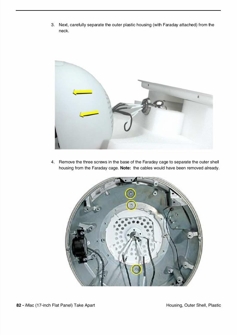
3. Next, carefully separate the outer plastic housing (with Faraday attached) from the
neck.
4. Remove the three screws in the base of the Faraday cage to separate the outer shell
housing from the Faraday cage. Note: the cables would have been removed already.

7/28/2019 iMAc 17inc
http://slidepdf.com/reader/full/imac-17inc 85/156
iM (17 i h Fl t P l) T k A t 83H i O t Sh ll Pl ti
Warning: Whenever the bottom housing is opened for service, you must do two things:
1.You must clean the original thermal film from all thermal interface mating surfaces,
and reapply thermal paste to the mating surfaces on the thermal pipe.
2. You must tighten the four torx screws on the bottom housing to a minimum of 17
in.-lbs. Use a torque driver (service tool 076-0899) to ensure that the thermal pipe is
firmly mated with the top base. If you do not have a torque driver, you must make
sure the screws are tightened by hand FIRMLY, BUT NOT FORCIBLY.
Warning: Failure to follow these steps could cause the computer to overheat
and damage internal components.
Refer to the topic “Thermal Paste Application” for detailed information.
7/28/2019 iMAc 17inc
http://slidepdf.com/reader/full/imac-17inc 86/156
84 iM (17 i h Fl t P l) T k A t Di l Fl t P l
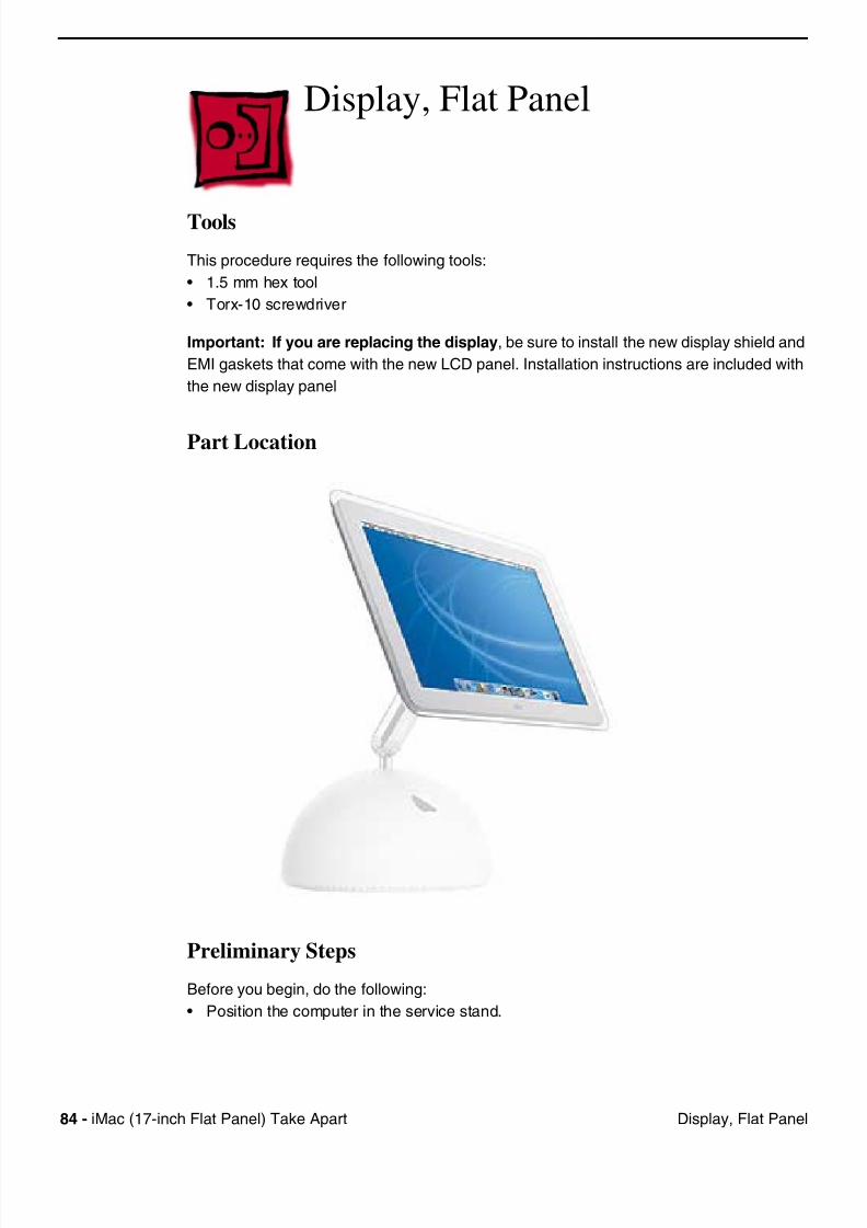
Display, Flat Panel
Tools
This procedure requires the following tools:
• 1.5 mm hex tool
• Torx-10 screwdriver
Important: If you are replacing the display, be sure to install the new display shield and
EMI gaskets that come with the new LCD panel. Installation instructions are included with
the new display panel
Part Location
Preliminary Steps
Before you begin, do the following:
• Position the computer in the service stand.
7/28/2019 iMAc 17inc
http://slidepdf.com/reader/full/imac-17inc 87/156
iM (17 i h Fl t P l) T k A t 85Di l Fl t P l
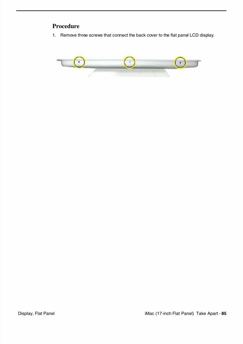
Procedure
1. Remove three screws that connect the back cover to the flat panel LCD display.
7/28/2019 iMAc 17inc
http://slidepdf.com/reader/full/imac-17inc 88/156
86 iM (17 i h Fl t P l) T k A t Di l Fl t P l
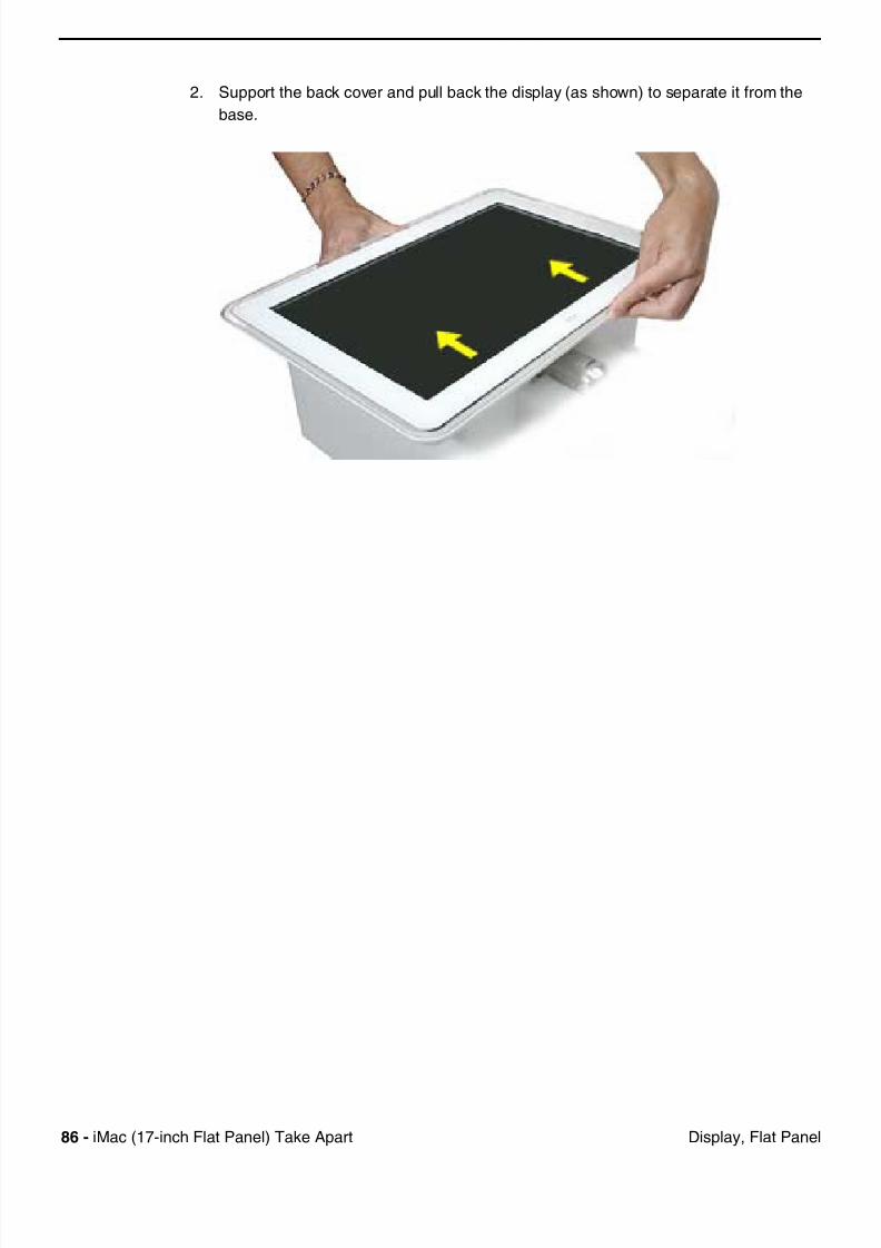
2. Support the back cover and pull back the display (as shown) to separate it from the
base.
7/28/2019 iMAc 17inc
http://slidepdf.com/reader/full/imac-17inc 89/156
iM (17 i h Fl t P l) T k A t 87Di l Fl t P l
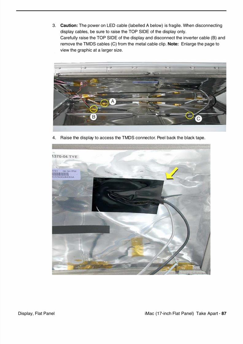
3. Caution: The power on LED cable (labelled A below) is fragile. When disconnecting
display cables, be sure to raise the TOP SIDE of the display only.
Carefully raise the TOP SIDE of the display and disconnect the inverter cable (B) and
remove the TMDS cables (C) from the metal cable clip. Note: Enlarge the page to
view the graphic at a larger size.
4. Raise the display to access the TMDS connector. Peel back the black tape.
7/28/2019 iMAc 17inc
http://slidepdf.com/reader/full/imac-17inc 90/156
88 iM (17 i h Fl t P l) T k A t Di l Fl t P l
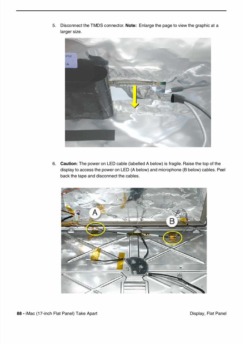
5. Disconnect the TMDS connector. Note: Enlarge the page to view the graphic at a
larger size.
6. Caution: The power on LED cable (labelled A below) is fragile. Raise the top of the
display to access the power on LED (A below) and microphone (B below) cables. Peel
back the tape and disconnect the cables.
7/28/2019 iMAc 17inc
http://slidepdf.com/reader/full/imac-17inc 91/156
iM (17 i h Fl t P l) T k A t 89Di l Fl t P l
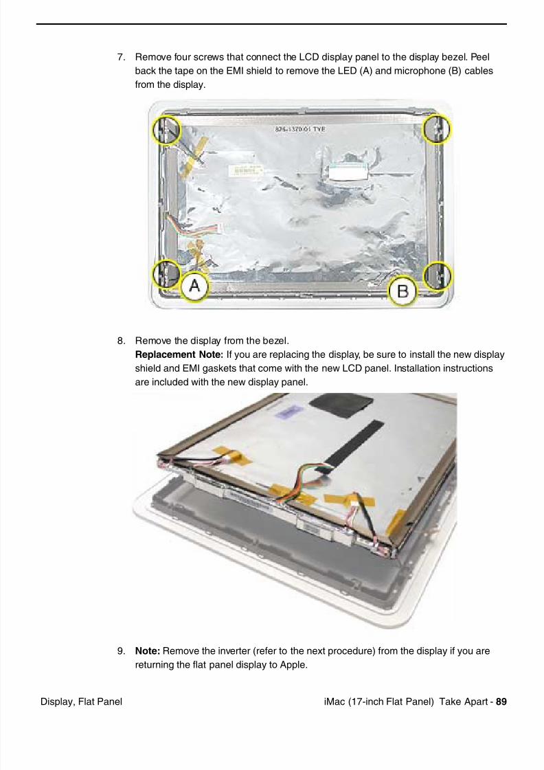
7. Remove four screws that connect the LCD display panel to the display bezel. Peel
back the tape on the EMI shield to remove the LED (A) and microphone (B) cables
from the display.
8. Remove the display from the bezel.
Replacement Note: If you are replacing the display, be sure to install the new display
shield and EMI gaskets that come with the new LCD panel. Installation instructions
are included with the new display panel.
9. Note: Remove the inverter (refer to the next procedure) from the display if you are
returning the flat panel display to Apple.
7/28/2019 iMAc 17inc
http://slidepdf.com/reader/full/imac-17inc 92/156
90 iM (17 i h Fl t P l) T k A t Di l Fl t P l
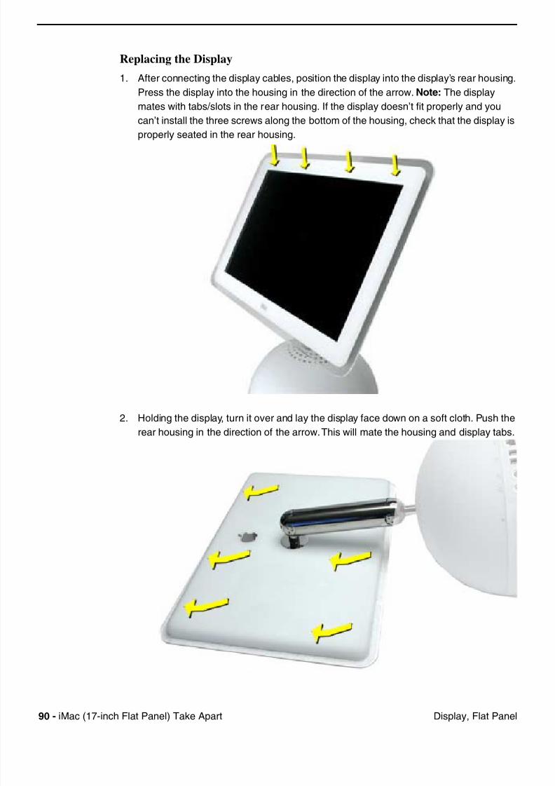
Replacing the Display
1. After connecting the display cables, position the display into the display’s rear housing.
Press the display into the housing in the direction of the arrow. Note: The display
mates with tabs/slots in the rear housing. If the display doesn’t fit properly and you
can’t install the three screws along the bottom of the housing, check that the display is
properly seated in the rear housing.
2. Holding the display, turn it over and lay the display face down on a soft cloth. Push the
rear housing in the direction of the arrow. This will mate the housing and display tabs.
7/28/2019 iMAc 17inc
http://slidepdf.com/reader/full/imac-17inc 93/156
iM (17 i h Fl t P l) T k A t 91Di l Fl t P l
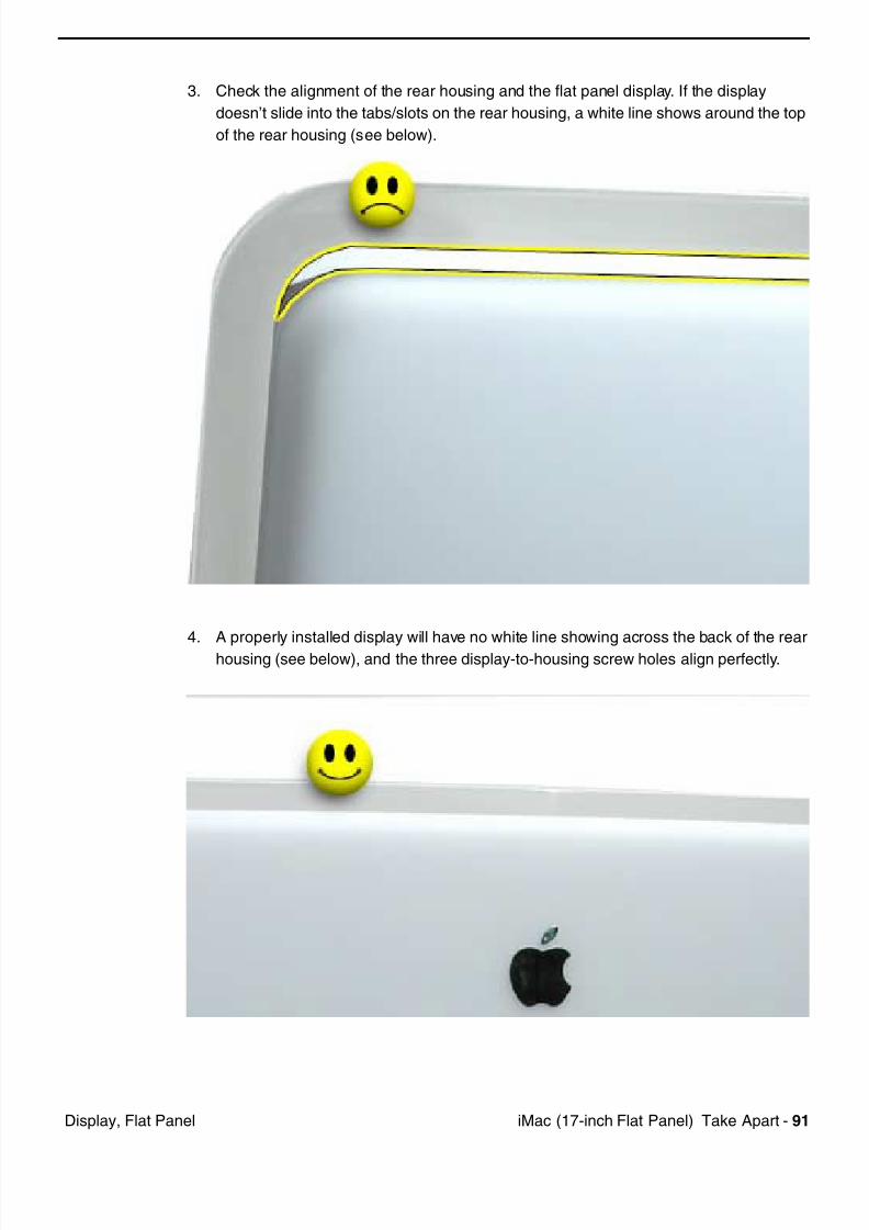
3. Check the alignment of the rear housing and the flat panel display. If the display
doesn’t slide into the tabs/slots on the rear housing, a white line shows around the top
of the rear housing (see below).
4. A properly installed display will have no white line showing across the back of the rear
housing (see below), and the three display-to-housing screw holes align perfectly.
7/28/2019 iMAc 17inc
http://slidepdf.com/reader/full/imac-17inc 94/156
92 iM (17 i h Fl t P l) T k A t I t
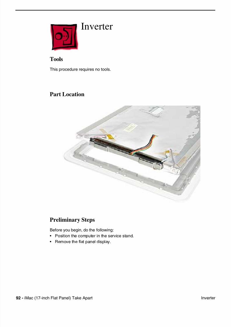
Inverter
Tools
This procedure requires no tools.
Part Location
Preliminary Steps
Before you begin, do the following:• Position the computer in the service stand.
• Remove the flat panel display.
7/28/2019 iMAc 17inc
http://slidepdf.com/reader/full/imac-17inc 95/156
iM (17 i h Fl t P l) T k A t 93I t
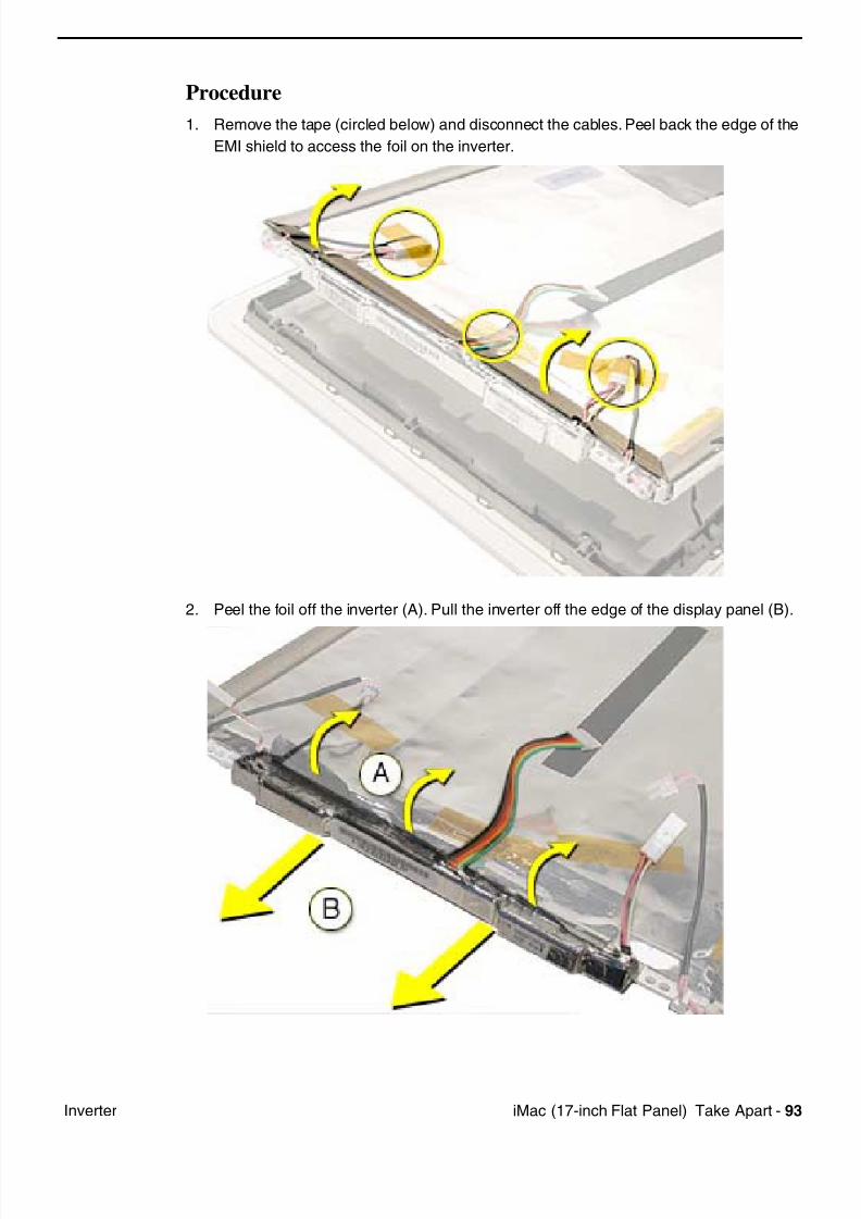
Procedure
1. Remove the tape (circled below) and disconnect the cables. Peel back the edge of the
EMI shield to access the foil on the inverter.
2. Peel the foil off the inverter (A). Pull the inverter off the edge of the display panel (B).
7/28/2019 iMAc 17inc
http://slidepdf.com/reader/full/imac-17inc 96/156
94 iM (17 i h Fl t P l) T k A t LED
LED
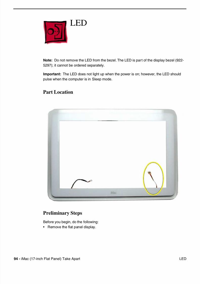
Note: Do not remove the LED from the bezel. The LED is part of the display bezel (922-
5297); it cannot be ordered separately.
Important: The LED does not light up when the power is on; however, the LED should
pulse when the computer is in Sleep mode.
Part Location
Preliminary Steps
Before you begin, do the following:
• Remove the flat panel display.
7/28/2019 iMAc 17inc
http://slidepdf.com/reader/full/imac-17inc 97/156
iM (17 i h Fl t P l) T k A t 95Mi h
Microphone
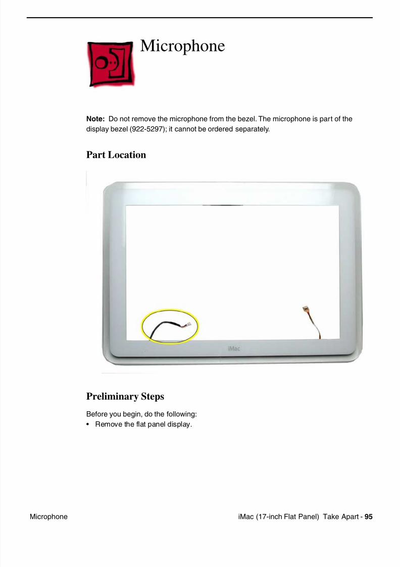
Note: Do not remove the microphone from the bezel. The microphone is part of the
display bezel (922-5297); it cannot be ordered separately.
Part Location
Preliminary Steps
Before you begin, do the following:
• Remove the flat panel display.
7/28/2019 iMAc 17inc
http://slidepdf.com/reader/full/imac-17inc 98/156
96 iM (17 i h Fl t P l) T k A t B k C Di l
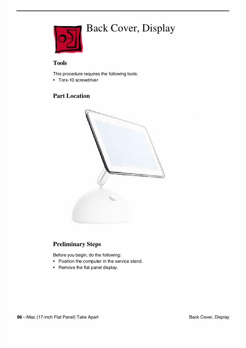
Back Cover, Display
Tools
This procedure requires the following tools:
• Torx-10 screwdriver
Part Location
Preliminary Steps
Before you begin, do the following:
• Position the computer in the service stand.
• Remove the flat panel display.
7/28/2019 iMAc 17inc
http://slidepdf.com/reader/full/imac-17inc 99/156
iM (17 i h Fl t P l) T k A t 97B k C Di l
Procedure
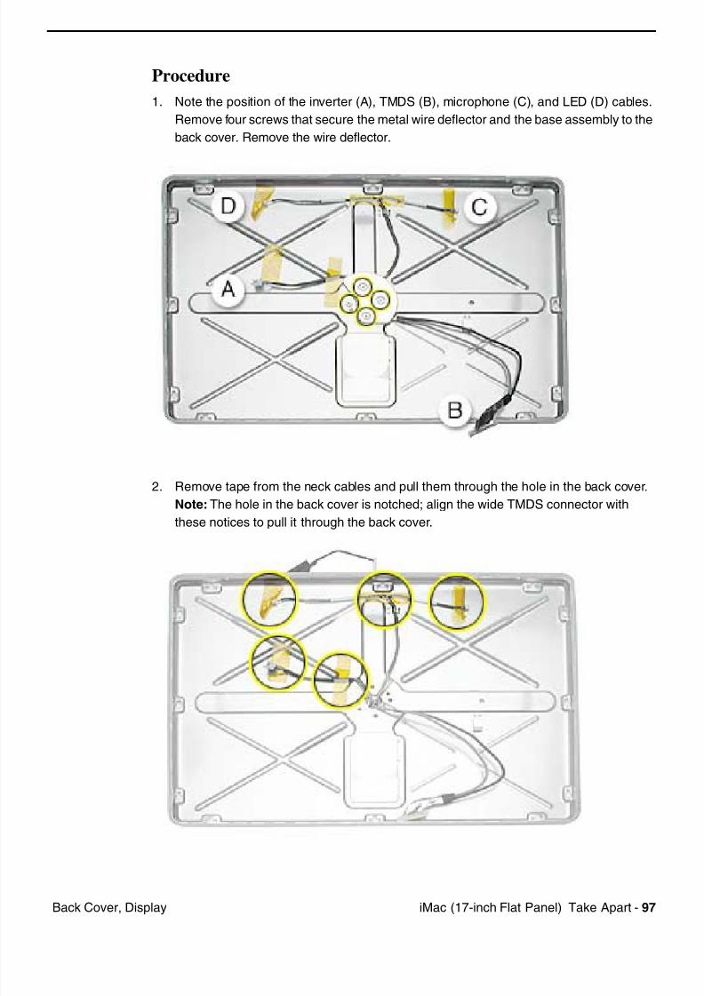
1. Note the position of the inverter (A), TMDS (B), microphone (C), and LED (D) cables.
Remove four screws that secure the metal wire deflector and the base assembly to the
back cover. Remove the wire deflector.
2. Remove tape from the neck cables and pull them through the hole in the back cover.
Note: The hole in the back cover is notched; align the wide TMDS connector with
these notices to pull it through the back cover.
7/28/2019 iMAc 17inc
http://slidepdf.com/reader/full/imac-17inc 100/156
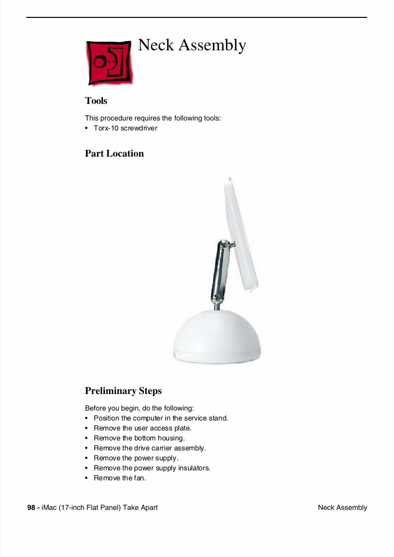
98 iM (17 i h Fl t P l) T k A t N k A bl
Neck Assembly
Tools
This procedure requires the following tools:
• Torx-10 screwdriver
Part Location
Preliminary Steps
Before you begin, do the following:
• Position the computer in the service stand.
• Remove the user access plate.
• Remove the bottom housing.
• Remove the drive carrier assembly.
• Remove the power supply.
• Remove the power supply insulators.
• Remove the fan.
7/28/2019 iMAc 17inc
http://slidepdf.com/reader/full/imac-17inc 101/156
iM (17 i h Fl t P l) T k A t 99N k A bl
• Remove the fan bracket.
• Remove the neck spoke retainer cap.
• Remove the blind mate connector screws.
• Remove the Faraday cage.
• Remove the outer plastic housing.
• Remove the flat panel display.
• Remove the back cover
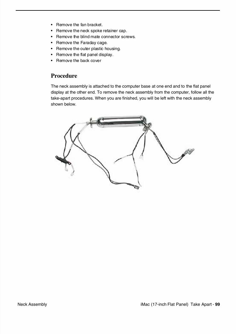
Procedure
The neck assembly is attached to the computer base at one end and to the flat panel
display at the other end. To remove the neck assembly from the computer, follow all the
take-apart procedures. When you are finished, you will be left with the neck assembly
shown below.
7/28/2019 iMAc 17inc
http://slidepdf.com/reader/full/imac-17inc 102/156
© 2002 Apple Computer Inc Al l rights reserved
Service Source
Troubleshooting
iMac (17-inch Flat Panel)
7/28/2019 iMAc 17inc
http://slidepdf.com/reader/full/imac-17inc 103/156
iM (17 i h Fl t P l) T bl h ti 1G l I f ti
General Information
What’s New and Different:1. Important: If you are replacing the display, be sure to install the new display shield and EMI gaskets that
come with the new LCD panel. Installation instructions are included with the new display panel.
Additional display shields/gasket kits are also available separately as a kit, part #076-0958.
2. The LED and microphone are part of the display bezel (922-5297); they cannot be ordered separately.
3. The LED functions differently on the iMac (17-inch Flat Panel). The LED does not light up when the
power is on; however, the LED should pulse when the computer is in Sleep mode.
4. Diagnostic test points have been added to the logic board. They are accessed through the user access
door. Use the test points to check the following:
• Battery
• 5V
• Main
• 12V
For more information, refer to the “Logic Board Battery” and “No Power” topics later in this
chapter.
5. Important: The CPU uses a thermal pipe to transfer heat away. This pipe makes a thermal connection to
the top metal chassis (Faraday cage) at two locations. These connecting points must be cleaned and
have new thermal paste applied each time the bottom housing is removed. If the mating surfaces are notcleaned and thermal paste is not used, the CPU may overheat and become damaged. There is no
exception to this. Note: Most service procedures require that the bottom housing is removed.
Refer to “Thermal Paste Application” mentioned later in this chapter or in the Take Apart
chapter.
6. The procedures for removing and replacing the display panel and the inverter board are new and
different. Refer to the Take Apart chapter for additional information. Important: Whenever the LCD
display (661-2715) is replaced, a display shield/gasket kit (076-0958) must be installed on the new panel.
Instructions for installing the shield/gasket kit are included with the new LCD panel.
7. The AirPort antenna cable is no longer bundled in the neck assembly. The antenna is now clipped to theoutside of the Faraday cage. Refer to the Take Apart chapter for additional information.
Important Things to Remember:
Service items that still apply to all flat-panel iMac computers:
1. Important: Whenever the logic board is separated from the bottom housing, you must install new
thermal pads to three surfaces on the bottom housing. The thermal pads help cool components on the
logic board. Failure to apply these pads whenever the logic board is separated from the bottom housing

7/28/2019 iMAc 17inc
http://slidepdf.com/reader/full/imac-17inc 104/156
2 iM (17 i h Fl t P l) T bl h ti G l I f ti
could cause these parts to overheat. Short term separation, where the thermal pads are not handled
excessively ( an exception would be if you are simply testing the logic board and only detach it for a few
minutes), does not require replacement. Refer to “Thermal Pad Installation” in this chapter for detailed
information.
Refer to the Take Apart chapter, “Thermal Pad Installation.”
2. Whenever the bottom housing is opened for service, you must do two things:
1.You must clean the original thermal film from the surfaces joining the thermal interface layer and
reapply thermal paste to the thermal pipe.
2. You must tighten the four torx screws on the bottom housing to a minimum of 17 in.-lbs. If you do
not have a torque driver, you will have to make sure these screws are tightened by hand FIRMLY,
BUT NOT FORCIBLY. Or, purchase the service tool (076-0899) in order to ensure the thermal pipe is
firmly mated with the top base. If the bottom housing is not securely attached to the base in this
fashion, the CPU may overheat and become damaged. Failure to follow either of these steps could
cause the computer to overheat and damage internal components.
Refer to the topic, “Thermal Paste Application” for detailed information.
3. Special service tools are required to perform some procedures. A service stand, 076-0898, to hold the
unit during take apart, and service cables, 076-0897, that allow the unit to be powered on while the
bottom housing is open. Important: The unit should not be powered on for more than five minutes with
the bottom housing open. If it is open longer, the CPU may overheat and become damaged.
7/28/2019 iMAc 17inc
http://slidepdf.com/reader/full/imac-17inc 105/156
iM (17 i h Fl t P l) T bl h ti 3G l I f ti
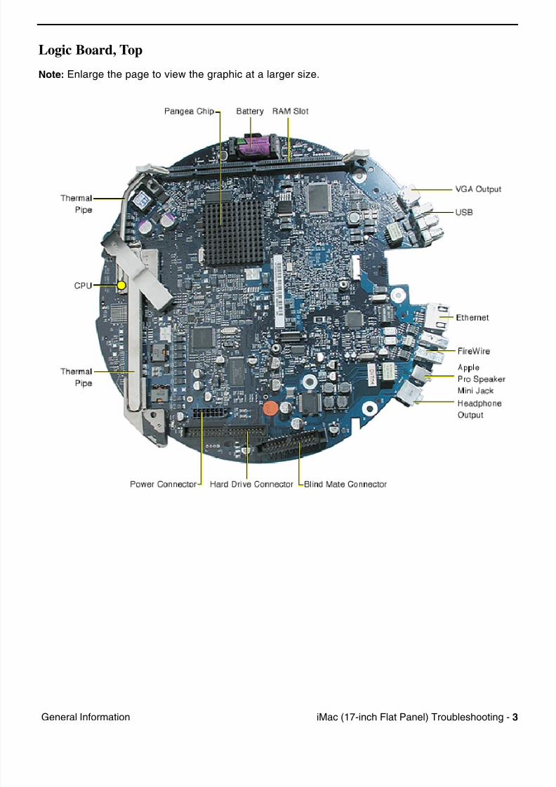
Logic Board, Top
Note: Enlarge the page to view the graphic at a larger size.
7/28/2019 iMAc 17inc
http://slidepdf.com/reader/full/imac-17inc 106/156
4 iM (17 i h Fl t P l) T bl h ti G l I f ti
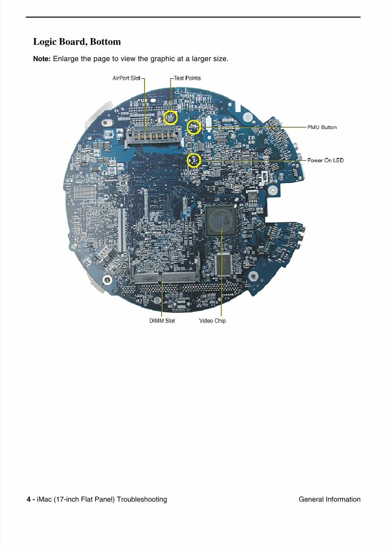
Logic Board, Bottom
Note: Enlarge the page to view the graphic at a larger size.
7/28/2019 iMAc 17inc
http://slidepdf.com/reader/full/imac-17inc 107/156
iM (17 i h Fl t P l) T bl h ti 5G l I f ti
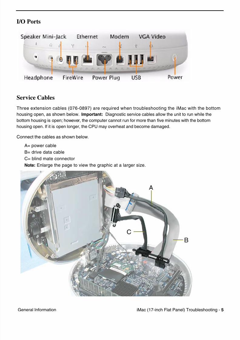
I/O Ports
Service Cables
Three extension cables (076-0897) are required when troubleshooting the iMac with the bottom
housing open, as shown below. Important: Diagnostic service cables allow the unit to run while the
bottom housing is open; however, the computer cannot run for more than five minutes with the bottom
housing open. If it is open longer, the CPU may overheat and become damaged.
Connect the cables as shown below.
A= power cable
B= drive data cable
C= blind mate connector
Note: Enlarge the page to view the graphic at a larger size.
7/28/2019 iMAc 17inc
http://slidepdf.com/reader/full/imac-17inc 108/156
6 iM (17 i h Fl t P l) T bl h ti G l I f ti
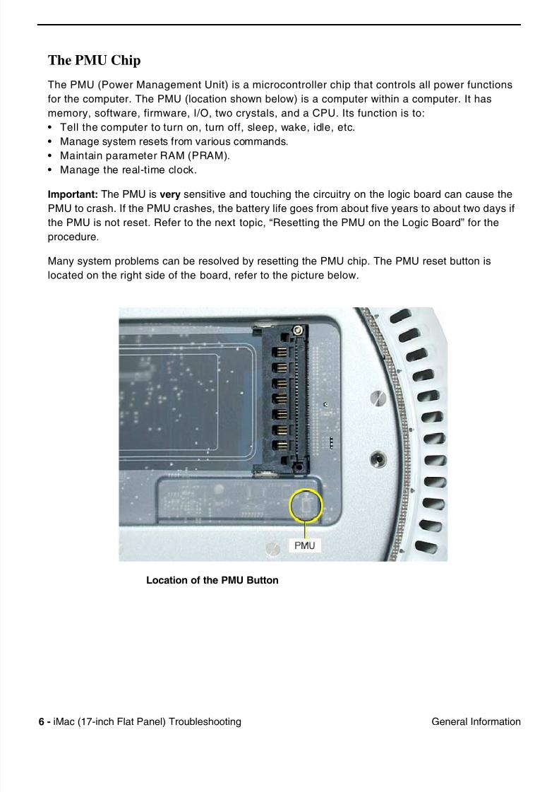
The PMU Chip
The PMU (Power Management Unit) is a microcontroller chip that controls all power functions
for the computer. The PMU (location shown below) is a computer within a computer. It has
memory, software, firmware, I/O, two crystals, and a CPU. Its function is to:
• Tell the computer to turn on, turn off, sleep, wake, idle, etc.
• Manage system resets from various commands.
• Maintain parameter RAM (PRAM).
• Manage the real-time clock.
Important: The PMU is very sensitive and touching the circuitry on the logic board can cause the
PMU to crash. If the PMU crashes, the battery life goes from about five years to about two days if
the PMU is not reset. Refer to the next topic, “Resetting the PMU on the Logic Board” for the
procedure.
Many system problems can be resolved by resetting the PMU chip. The PMU reset button is
located on the right side of the board, refer to the picture below.
Location of the PMU Button
7/28/2019 iMAc 17inc
http://slidepdf.com/reader/full/imac-17inc 109/156
iM (17 i h Fl t P l) T bl h ti 7G l I f ti
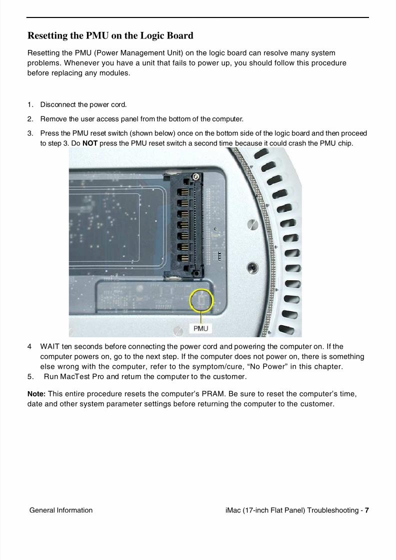
Resetting the PMU on the Logic Board
Resetting the PMU (Power Management Unit) on the logic board can resolve many system
problems. Whenever you have a unit that fails to power up, you should follow this procedure
before replacing any modules.
1. Disconnect the power cord.
2. Remove the user access panel from the bottom of the computer.
3. Press the PMU reset switch (shown below) once on the bottom side of the logic board and then proceed
to step 3. Do NOT press the PMU reset switch a second time because it could crash the PMU chip.
4 WAIT ten seconds before connecting the power cord and powering the computer on. If the
computer powers on, go to the next step. If the computer does not power on, there is something
else wrong with the computer, refer to the symptom/cure, “No Power” in this chapter.
5. Run MacTest Pro and return the computer to the customer.
Note: This entire procedure resets the computer’s PRAM. Be sure to reset the computer’s time,date and other system parameter settings before returning the computer to the customer.
7/28/2019 iMAc 17inc
http://slidepdf.com/reader/full/imac-17inc 110/156
8 iM (17 i h Fl t P l) T bl h ti G l I f ti
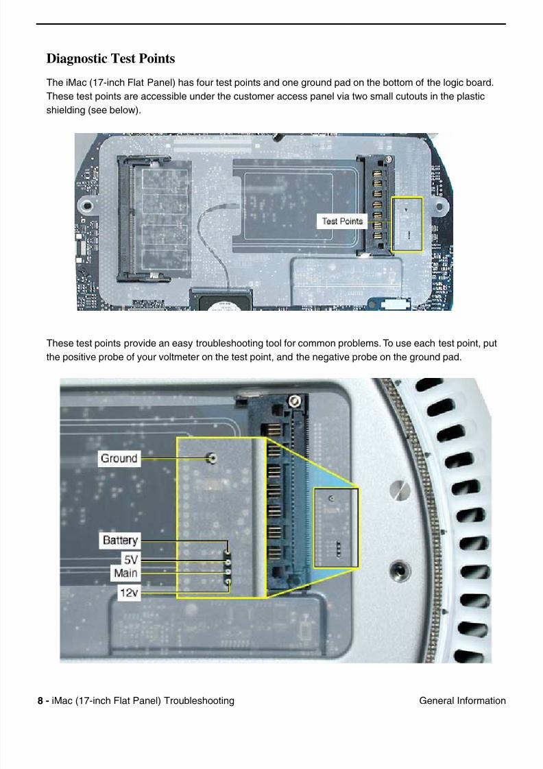
Diagnostic Test Points
The iMac (17-inch Flat Panel) has four test points and one ground pad on the bottom of the logic board.
These test points are accessible under the customer access panel via two small cutouts in the plastic
shielding (see below).
These test points provide an easy troubleshooting tool for common problems. To use each test point, put
the positive probe of your voltmeter on the test point, and the negative probe on the ground pad.
7/28/2019 iMAc 17inc
http://slidepdf.com/reader/full/imac-17inc 111/156
iM (17 i h Fl t P l) T bl h ti 9G l I f ti
Logic Board Battery
Important: Apple highly recommends removing the battery when handling the logic board. Make
sure to use proper ESD protection when handling modules.
The battery on the logic board controls the stored system settings, such as date and time. It is only
necessary to test the battery when you can’t power on the computer, or the date and time are reset
every time the AC power is removed.
The battery is also used to power the PMU chip (because the PMU chip keeps time and must always
be running) when the computer is unplugged from the wall (AC power). The PMU is very sensitive
and touching any circuitry that is connected to the PMU can cause it to crash. If the PMU crashes,
the battery life goes from about five years to about two days if the PMU is not reset. Once the
battery goes dead, the PMU will reset the time and date every time the AC power is removed. To fix
this situation, replace the battery and reset the PMU (refer to “Resetting the PMU on the Logic
Board” mentioned earlier in this chapter).
If the computer has a “No Power” situation, check the battery before replacing modules.
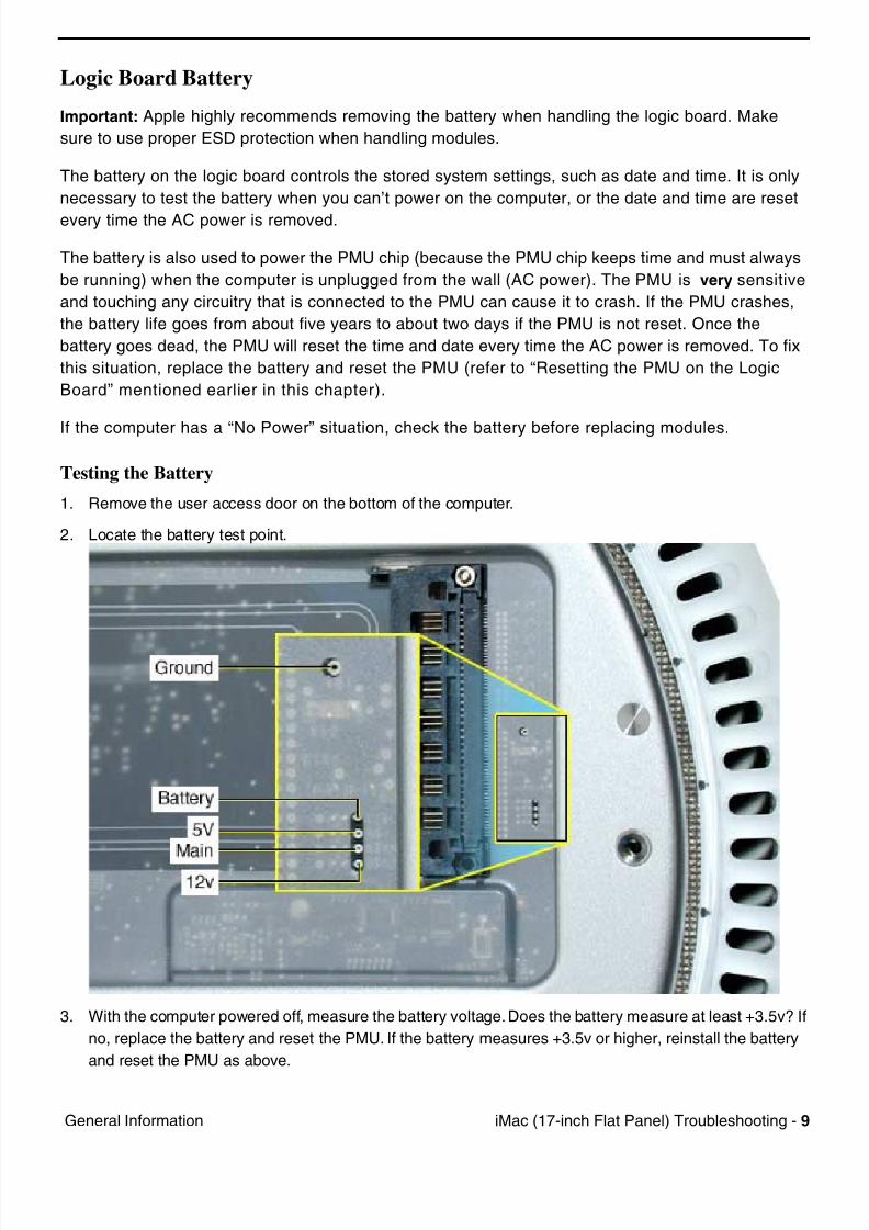
Testing the Battery
1. Remove the user access door on the bottom of the computer.
2. Locate the battery test point.
3. With the computer powered off, measure the battery voltage. Does the battery measure at least +3.5v? If
no, replace the battery and reset the PMU. If the battery measures +3.5v or higher, reinstall the battery
and reset the PMU as above.

7/28/2019 iMAc 17inc
http://slidepdf.com/reader/full/imac-17inc 112/156
10 iM (17 i h Fl t P l) T bl h ti G l I f ti
4. Connect the power cord and power up the system again.
Warning: Whenever the bottom housing is opened for service, you must do two things:
1. You must clean and reapply thermal paste to the thermal pipe surface.
2. You must tighten the four torx bolts on the base unit to a minimum of 17 in.– lbs. Failure to follow
either of these steps could cause the computer to overheat nd damage internal components.
Refer to the next topic, “Thermal Paste Application” for detailed information.
7/28/2019 iMAc 17inc
http://slidepdf.com/reader/full/imac-17inc 113/156
iM (17 i h Fl t P l) T bl h ti 11G l I f ti
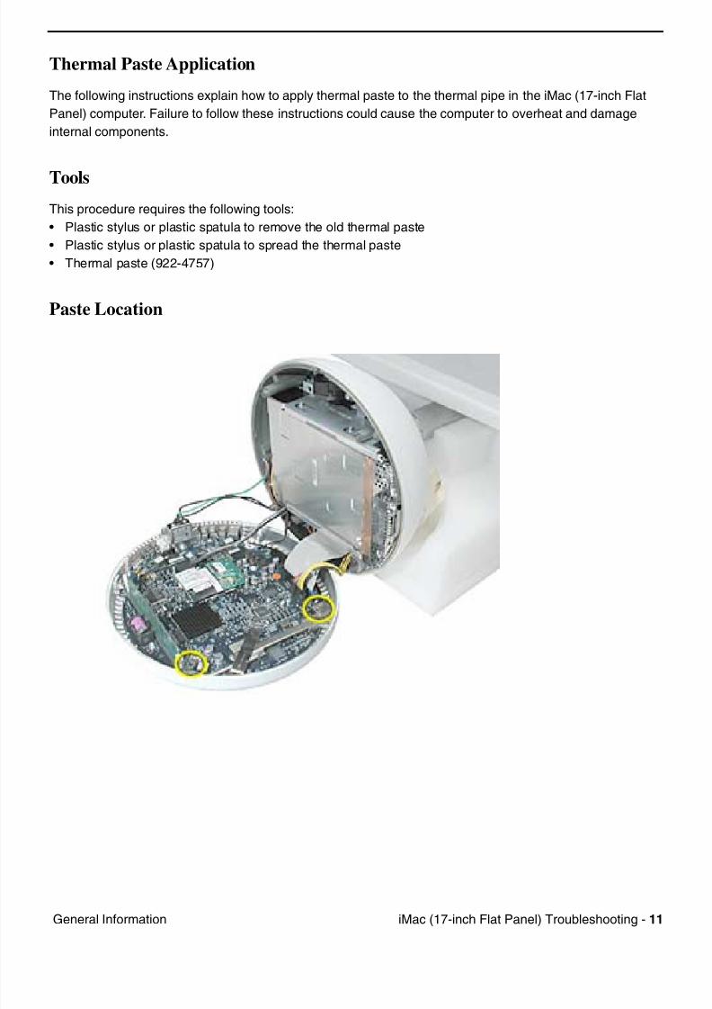
Thermal Paste Application
The following instructions explain how to apply thermal paste to the thermal pipe in the iMac (17-inch Flat
Panel) computer. Failure to follow these instructions could cause the computer to overheat and damage
internal components.
Tools
This procedure requires the following tools:
• Plastic stylus or plastic spatula to remove the old thermal paste
• Plastic stylus or plastic spatula to spread the thermal paste
• Thermal paste (922-4757)
Paste Location
7/28/2019 iMAc 17inc
http://slidepdf.com/reader/full/imac-17inc 114/156
12 iM (17 i h Fl t P l) T bl h ti G l I f ti
Procedure
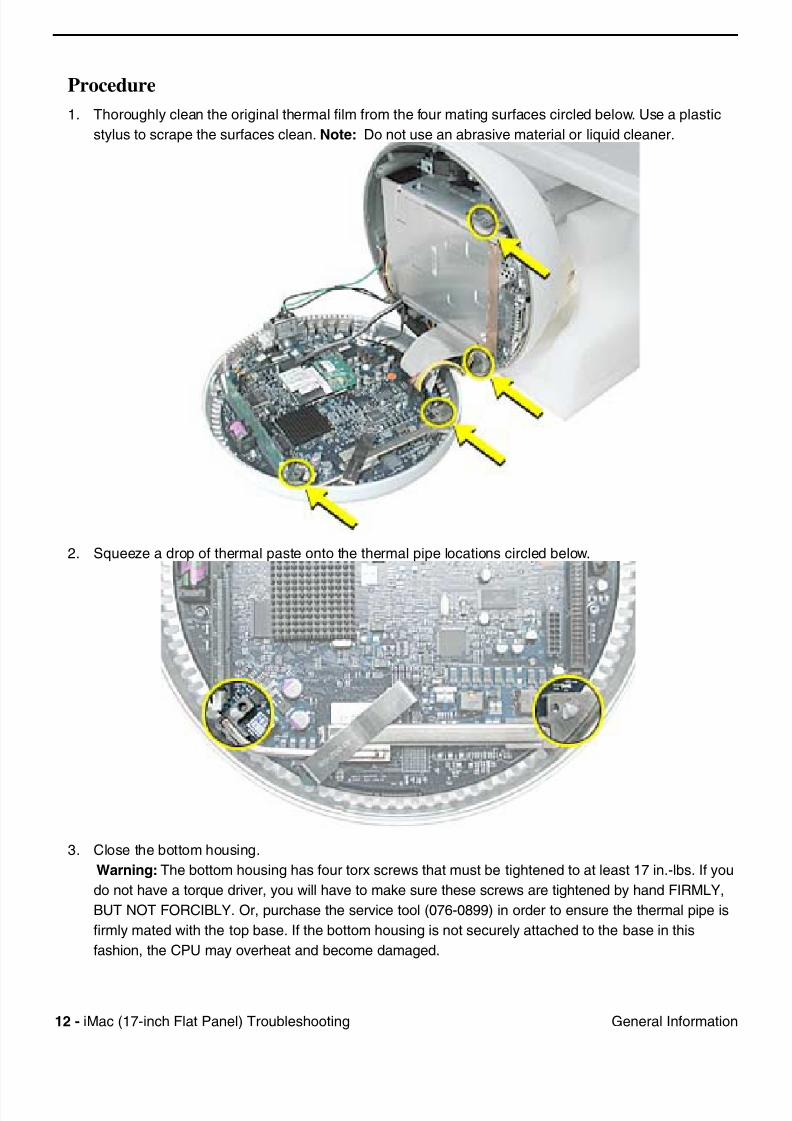
1. Thoroughly clean the original thermal film from the four mating surfaces circled below. Use a plastic
stylus to scrape the surfaces clean. Note: Do not use an abrasive material or liquid cleaner.
2. Squeeze a drop of thermal paste onto the thermal pipe locations circled below.
3. Close the bottom housing.
Warning: The bottom housing has four torx screws that must be tightened to at least 17 in.-lbs. If you
do not have a torque driver, you will have to make sure these screws are tightened by hand FIRMLY,
BUT NOT FORCIBLY. Or, purchase the service tool (076-0899) in order to ensure the thermal pipe is
firmly mated with the top base. If the bottom housing is not securely attached to the base in this
fashion, the CPU may overheat and become damaged.
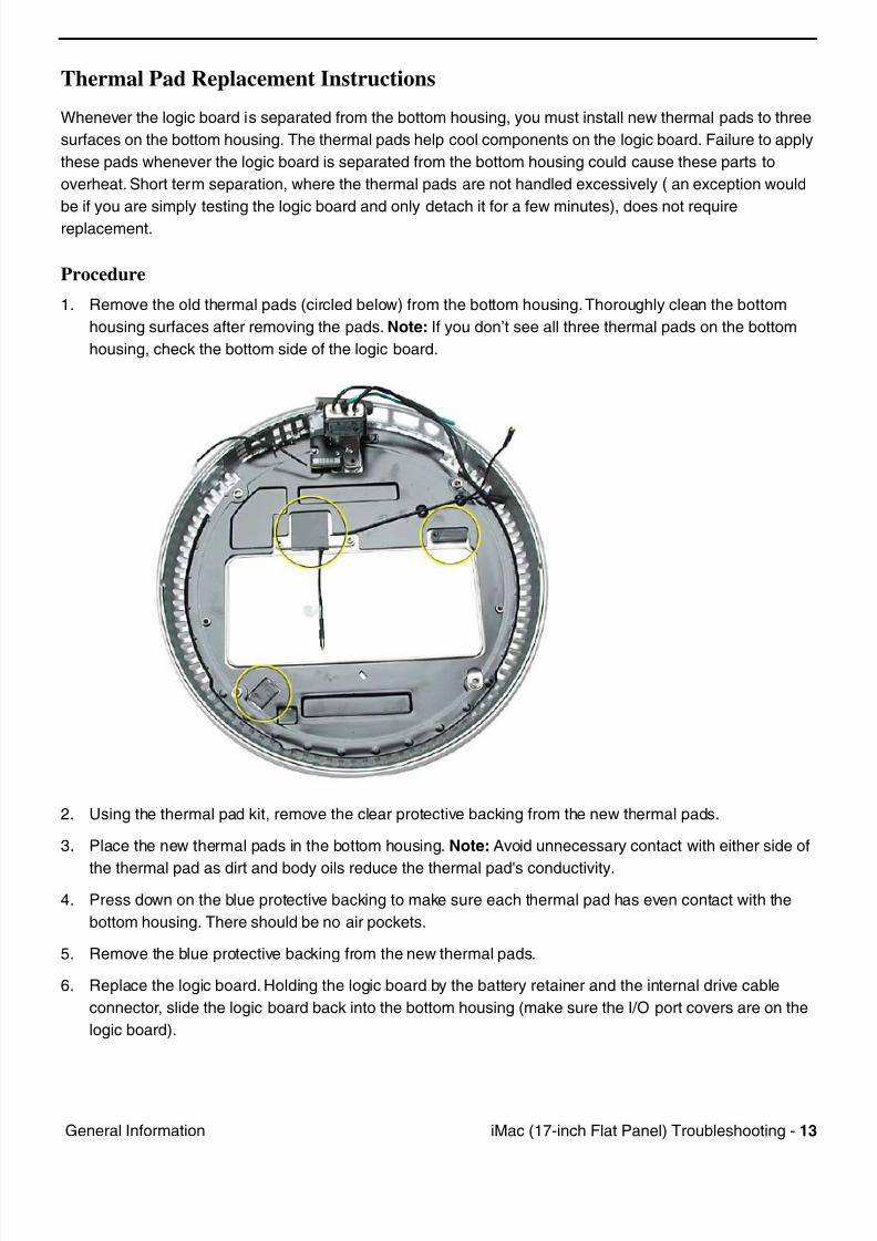
7/28/2019 iMAc 17inc
http://slidepdf.com/reader/full/imac-17inc 115/156
iM (17 i h Fl t P l) T bl h ti 13G l I f ti
Thermal Pad Replacement Instructions
Whenever the logic board is separated from the bottom housing, you must install new thermal pads to three
surfaces on the bottom housing. The thermal pads help cool components on the logic board. Failure to apply
these pads whenever the logic board is separated from the bottom housing could cause these parts to
overheat. Short term separation, where the thermal pads are not handled excessively ( an exception would
be if you are simply testing the logic board and only detach it for a few minutes), does not require
replacement.
Procedure
1. Remove the old thermal pads (circled below) from the bottom housing. Thoroughly clean the bottom
housing surfaces after removing the pads. Note: If you don’t see all three thermal pads on the bottom
housing, check the bottom side of the logic board.
2. Using the thermal pad kit, remove the clear protective backing from the new thermal pads.
3. Place the new thermal pads in the bottom housing. Note: Avoid unnecessary contact with either side of
the thermal pad as dirt and body oils reduce the thermal pad's conductivity.
4. Press down on the blue protective backing to make sure each thermal pad has even contact with the
bottom housing. There should be no air pockets.
5. Remove the blue protective backing from the new thermal pads.
6. Replace the logic board. Holding the logic board by the battery retainer and the internal drive cable
connector, slide the logic board back into the bottom housing (make sure the I/O port covers are on the
logic board).
7/28/2019 iMAc 17inc
http://slidepdf.com/reader/full/imac-17inc 116/156
14 iM (17 i h Fl t P l) T bl h ti S t Ch t
Symptom Charts
How to Use the Symptom Charts
The Symptom Charts included in this chapter will help you diagnose specific symptoms related to the
product. Because cures are listed on the charts in the order of most likely solution, try the cures in the
order presented. Verify whether or not the product continues to exhibit the symptom. If the symptom
persists, try the next cure.
Note: If you have replaced a module, reinstall the original module before you proceed to the next cure.
Apple Hardware TestApple Hardware Test is a diagnostic tool for detecting problems with Apple internal hardware components
such as logic board, memory, modem, video RAM, and Apple AirPort Card. The test does not check
externally connected hardware components such as USB or FireWire devices; it also does not check non-
Apple devices such as third-party PCI cards.
Note: The most recent Apple Hardware Test software can be downloaded from the CD Images page on
AppleCare Service Source; go to the Service Source home page and select ‘Disc Images’ from the quick-
click table.
Error Codes
If Apple Hardware Test detects a problem with a computer, it displays an error code, which is defined in the
product's Error Code List. Consult the list for appropriate repair procedures associated with the code.
All Error Code Lists are included in the Service Diagnostics Matrix, Knowledge Base article 112125. You
can also access this matrix by clicking the Service Diagnostics rollover link under any of the product areas
on the Service Source home page.
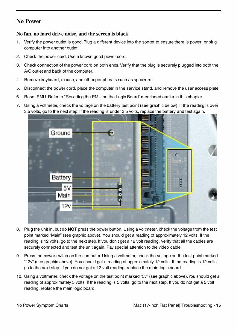
7/28/2019 iMAc 17inc
http://slidepdf.com/reader/full/imac-17inc 117/156
iM (17 i h Fl t P l) T bl h ti 15N P S t Ch t
No Power
No fan, no hard drive noise, and the screen is black.
1. Verify the power outlet is good. Plug a different device into the socket to ensure there is power, or plug
computer into another outlet.
2. Check the power cord. Use a known good power cord.3. Check connection of the power cord on both ends. Verify that the plug is securely plugged into both the
A/C outlet and back of the computer.
4. Remove keyboard, mouse, and other peripherals such as speakers.
5. Disconnect the power cord, place the computer in the service stand, and remove the user access plate.
6. Reset PMU. Refer to “Resetting the PMU on the Logic Board” mentioned earlier in this chapter.
7. Using a voltmeter, check the voltage on the battery test point (see graphic below). If the reading is over
3.5 volts, go to the next step. If the reading is under 3.5 volts, replace the battery and test again.
8. Plug the unit in, but do NOT press the power button. Using a voltmeter, check the voltage from the test
point marked “Main” (see graphic above). You should get a reading of approximately 12 volts. If thereading is 12 volts, go to the next step. If you don’t get a 12 volt reading, verify that all the cables are
securely connected and test the unit again. Pay special attention to the video cable.
9. Press the power switch on the computer. Using a voltmeter, check the voltage on the test point marked
“12v” (see graphic above). You should get a reading of approximately 12 volts. If the reading is 12 volts,
go to the next step. If you do not get a 12 volt reading, replace the main logic board.
10. Using a voltmeter, check the voltage on the test point marked “5v” (see graphic above). You should get a
reading of approximately 5 volts. If the reading is 5 volts, go to the next step. If you do not get a 5 volt
reading, replace the main logic board.
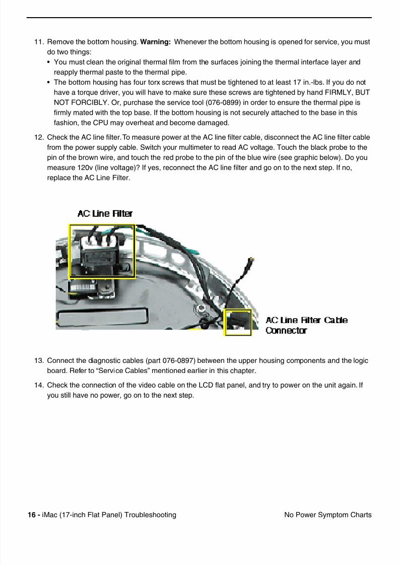
7/28/2019 iMAc 17inc
http://slidepdf.com/reader/full/imac-17inc 118/156
16 iM (17 i h Fl t P l) T bl h ti N P S t Ch t
11. Remove the bottom housing. Warning: Whenever the bottom housing is opened for service, you must
do two things:
• You must clean the original thermal film from the surfaces joining the thermal interface layer and
reapply thermal paste to the thermal pipe.
• The bottom housing has four torx screws that must be tightened to at least 17 in.-lbs. If you do not
have a torque driver, you will have to make sure these screws are tightened by hand FIRMLY, BUT
NOT FORCIBLY. Or, purchase the service tool (076-0899) in order to ensure the thermal pipe is
firmly mated with the top base. If the bottom housing is not securely attached to the base in this
fashion, the CPU may overheat and become damaged.
12. Check the AC line filter. To measure power at the AC line filter cable, disconnect the AC line filter cable
from the power supply cable. Switch your multimeter to read AC voltage. Touch the black probe to the
pin of the brown wire, and touch the red probe to the pin of the blue wire (see graphic below). Do you
measure 120v (line voltage)? If yes, reconnect the AC line filter and go on to the next step. If no,
replace the AC Line Filter.
13. Connect the diagnostic cables (part 076-0897) between the upper housing components and the logic
board. Refer to “Service Cables” mentioned earlier in this chapter.
14. Check the connection of the video cable on the LCD flat panel, and try to power on the unit again. If
you still have no power, go on to the next step.
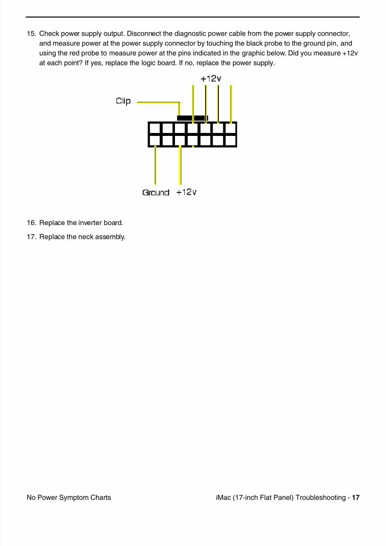
7/28/2019 iMAc 17inc
http://slidepdf.com/reader/full/imac-17inc 119/156
iM (17 i h Fl t P l) T bl h ti 17N P S t Ch t
15. Check power supply output. Disconnect the diagnostic power cable from the power supply connector,
and measure power at the power supply connector by touching the black probe to the ground pin, and
using the red probe to measure power at the pins indicated in the graphic below. Did you measure +12v
at each point? If yes, replace the logic board. If no, replace the power supply.
16. Replace the inverter board.
17. Replace the neck assembly.
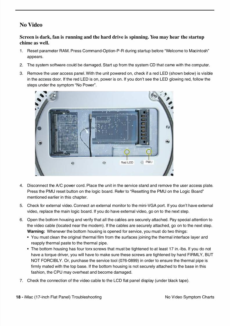
7/28/2019 iMAc 17inc
http://slidepdf.com/reader/full/imac-17inc 120/156
18 iM (17 i h Fl t P l) T bl h ti N Vid S t Ch t
No Video
Screen is dark, fan is running and the hard drive is spinning. You may hear the startup
chime as well.
1. Reset parameter RAM. Press Command-Option-P-R during startup before “Welcome to Macintosh”
appears.
2. The system software could be damaged. Start up from the system CD that came with the computer.
3. Remove the user access panel. With the unit powered on, check if a red LED (shown below) is visible
in the access door. If the red LED is on, power is on. If you don’t see the LED glowing red, follow the
steps under the symptom “No Power”.
4. Disconnect the A/C power cord. Place the unit in the service stand and remove the user access plate.
Press the PMU reset button on the logic board. Refer to “Resetting the PMU on the Logic Board”
mentioned earlier in this chapter.
5. Check for external video. Connect an external monitor to the mini-VGA port. If you don’t have external
video, replace the main logic board. If you do have external video, go on to the next step.
6. Open the bottom housing and verify that all the cables are securely attached. Pay special attention to
the video cable (located near the modem). If the cables are securely attached, go on to the next step.
Warning: Whenever the bottom housing is opened for service, you must do two things:
• You must clean the original thermal film from the surfaces joining the thermal interface layer and
reapply thermal paste to the thermal pipe.
• The bottom housing has four torx screws that must be tightened to at least 17 in.-lbs. If you do not
have a torque driver, you will have to make sure these screws are tightened by hand FIRMLY, BUT
NOT FORCIBLY. Or, purchase the service tool (076-0899) in order to ensure the thermal pipe is
firmly mated with the top base. If the bottom housing is not securely attached to the base in this
fashion, the CPU may overheat and become damaged.
7. Check the connection of the video cable to the LCD flat panel display (under black tape).

7/28/2019 iMAc 17inc
http://slidepdf.com/reader/full/imac-17inc 121/156
iM (17 i h Fl t P l) T bl h ti 19N Vid S t Ch t
8. Replace the inverter board.
9. Replace the LCD display. Important: If you are replacing the display, be sure to install the new display
shield and EMI gaskets that come with the new LCD panel. Installation instructions are included with the
new display panel. Additional display shields/gasket kits are also available separately as a kit, part #076-
0958.
10. Replace the neck assembly
11. Replace the logic board.
12. Replace the power supply board.
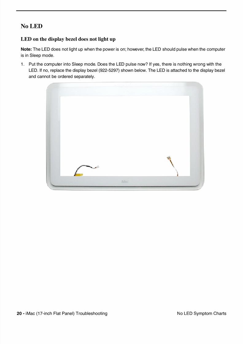
7/28/2019 iMAc 17inc
http://slidepdf.com/reader/full/imac-17inc 122/156
20 iM (17 i h Fl t P l) T bl h ti N LED S t Ch t
No LED
LED on the display bezel does not light up
Note: The LED does not light up when the power is on; however, the LED should pulse when the computer
is in Sleep mode.
1. Put the computer into Sleep mode. Does the LED pulse now? If yes, there is nothing wrong with the
LED. If no, replace the display bezel (922-5297) shown below. The LED is attached to the display bezel
and cannot be ordered separately.
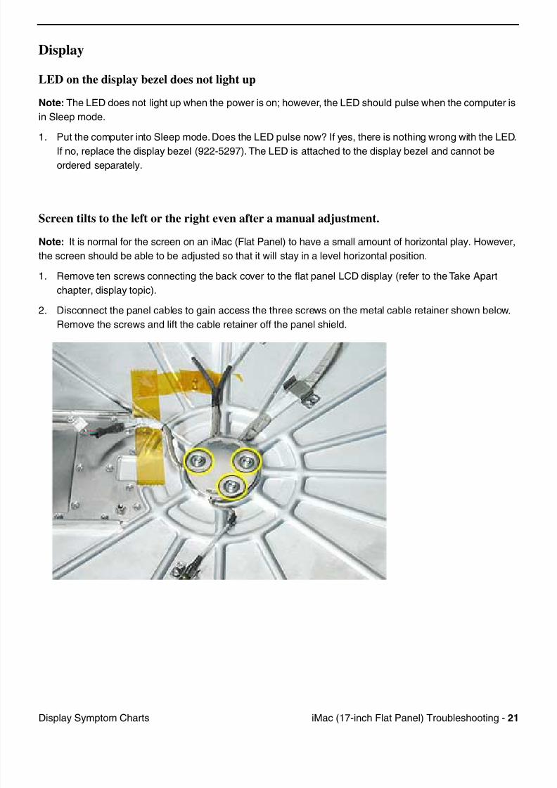
7/28/2019 iMAc 17inc
http://slidepdf.com/reader/full/imac-17inc 123/156
iM (17 i h Fl t P l) T bl h ti 21Di l S t Ch t
Display
LED on the display bezel does not light up
Note: The LED does not light up when the power is on; however, the LED should pulse when the computer is
in Sleep mode.
1. Put the computer into Sleep mode. Does the LED pulse now? If yes, there is nothing wrong with the LED.If no, replace the display bezel (922-5297). The LED is attached to the display bezel and cannot be
ordered separately.
Screen tilts to the left or the right even after a manual adjustment.
Note: It is normal for the screen on an iMac (Flat Panel) to have a small amount of horizontal play. However,
the screen should be able to be adjusted so that it will stay in a level horizontal position.
1. Remove ten screws connecting the back cover to the flat panel LCD display (refer to the Take Apartchapter, display topic).
2. Disconnect the panel cables to gain access the three screws on the metal cable retainer shown below.
Remove the screws and lift the cable retainer off the panel shield.
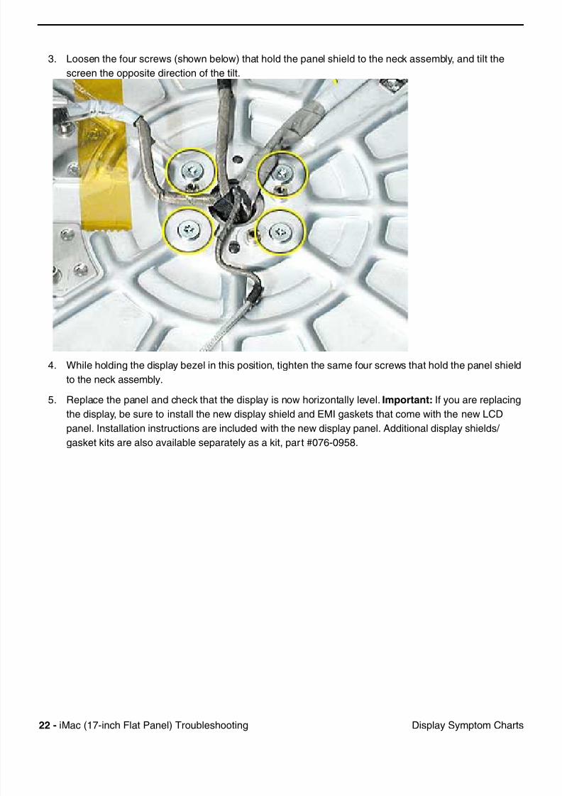
7/28/2019 iMAc 17inc
http://slidepdf.com/reader/full/imac-17inc 124/156
22 iM (17 i h Fl t P l) T bl h ti Di l S t Ch t
3. Loosen the four screws (shown below) that hold the panel shield to the neck assembly, and tilt the
screen the opposite direction of the tilt.
4. While holding the display bezel in this position, tighten the same four screws that hold the panel shield
to the neck assembly.
5. Replace the panel and check that the display is now horizontally level. Important: If you are replacing
the display, be sure to install the new display shield and EMI gaskets that come with the new LCDpanel. Installation instructions are included with the new display panel. Additional display shields/
gasket kits are also available separately as a kit, part #076-0958.
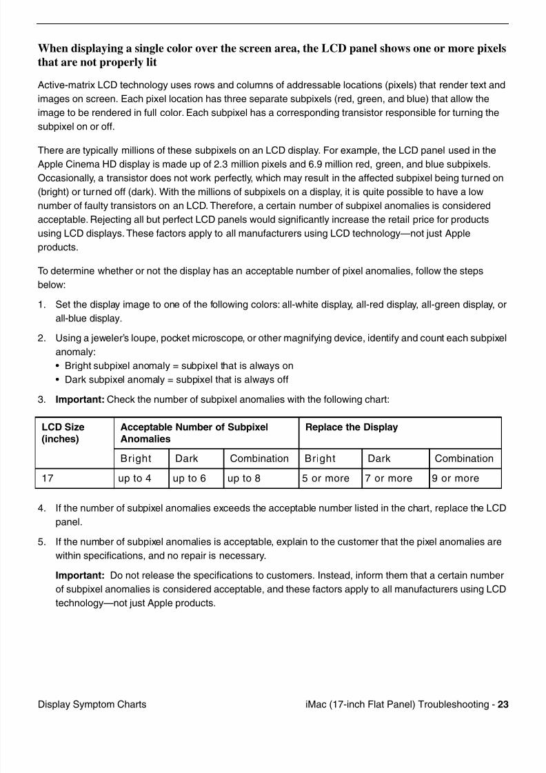
7/28/2019 iMAc 17inc
http://slidepdf.com/reader/full/imac-17inc 125/156
iM (17 i h Fl t P l) T bl h ti 23Di l S t Ch t
When displaying a single color over the screen area, the LCD panel shows one or more pixels
that are not properly lit
Active-matrix LCD technology uses rows and columns of addressable locations (pixels) that render text and
images on screen. Each pixel location has three separate subpixels (red, green, and blue) that allow the
image to be rendered in full color. Each subpixel has a corresponding transistor responsible for turning the
subpixel on or off.
There are typically millions of these subpixels on an LCD display. For example, the LCD panel used in the
Apple Cinema HD display is made up of 2.3 million pixels and 6.9 million red, green, and blue subpixels.
Occasionally, a transistor does not work perfectly, which may result in the affected subpixel being turned on
(bright) or turned off (dark). With the millions of subpixels on a display, it is quite possible to have a low
number of faulty transistors on an LCD. Therefore, a certain number of subpixel anomalies is considered
acceptable. Rejecting all but perfect LCD panels would significantly increase the retail price for products
using LCD displays. These factors apply to all manufacturers using LCD technology—not just Apple
products.
To determine whether or not the display has an acceptable number of pixel anomalies, follow the stepsbelow:
1. Set the display image to one of the following colors: all-white display, all-red display, all-green display, or
all-blue display.
2. Using a jeweler’s loupe, pocket microscope, or other magnifying device, identify and count each subpixel
anomaly:
• Bright subpixel anomaly = subpixel that is always on
• Dark subpixel anomaly = subpixel that is always off
3. Important: Check the number of subpixel anomalies with the following chart:
4. If the number of subpixel anomalies exceeds the acceptable number listed in the chart, replace the LCD
panel.
5. If the number of subpixel anomalies is acceptable, explain to the customer that the pixel anomalies arewithin specifications, and no repair is necessary.
Important: Do not release the specifications to customers. Instead, inform them that a certain number
of subpixel anomalies is considered acceptable, and these factors apply to all manufacturers using LCD
technology—not just Apple products.
LCD Size(inches)
Acceptable Number of SubpixelAnomalies
Replace the Display
Bright Dark Combination Bright Dark Combination
17 up to 4 up to 6 up to 8 5 or more 7 or more 9 or more

7/28/2019 iMAc 17inc
http://slidepdf.com/reader/full/imac-17inc 126/156
24 iM (17 i h Fl t P l) T bl h ti H d D i S t Ch t
Hard Drive
Hard Drive won’t mount to the desktop
1. Disconnect any connected peripherals.
2. Boot from the system CD that came with the computer and see if the hard drive mounts on the
desktop.
3. Launch Drive Setup and update the hard drive driver.
4. If no hard drive is found in Drive Setup, verify the hard drive cable connections.
5. Replace the hard drive cable.
6. Replace the hard drive.
7. Replace the logic board.
Flashing question mark appears on the screen1. Boot from the system CD that came with the computer and see if the hard drive mounts on the
desktop.
2. Launch Drive Setup and update the hard drive driver.
3. If no hard drive is found in Drive Setup, verify the hard drive cable connections.
4. Replace the hard drive cable.
5. Reinstall the software drivers for the hard drive.
6. Reinstall system software. Backup the data first.
7. Reinitiation the hard drive.
8. Replace the hard drive.
9. Replace the logic board.
System hangs during normal startup process
1. Boot from the system CD that came with the computer and see if the hard drive mounts on the
desktop.
2. Using Drive Setup, reinstall the system software drivers for the hard drive.
3. Using Drive Setup, reinitiation the hard drive.
4. Check all cable connections to and from the hard drive.
5. Replace the hard drive cable.
6. Replace the hard drive.
7. Replace the logic board.
7/28/2019 iMAc 17inc
http://slidepdf.com/reader/full/imac-17inc 127/156
iM (17 i h Fl t P l) T bl h ti 25O ti l D i S t Ch t
Optical Drive
Optical drive won’t mount to the desktop
1. Try cleaning the disc. If it is dirty or scratched, it may not mount.
2. Try a different disc.
3. Boot from Apple Hardware Test (hold down the “C” key at startup) or boot from the system install CD(use Startup Manager, hold down the Option key at startup).
4. Perform a clean install with the CD that came with the computer.
5. Replace the optical drive cable.
6. Replace the optical drive.
7. Replace the logic board.
Can’t boot from the optical drive
1. Try cleaning the disc. If it is dirty or scratched, it may not mount.
2. Try a different disc.
3. Boot from Apple Hardware Test (hold down the “C” key at startup) or boot from the system install CD
(use Startup Manager, hold down the Option key at startup).
4. Perform a clean install with the CD that came with the computer.
5. Replace the optical drive cable.
6. Replace the optical drive.
7. Replace the logic board.
Optical disc constantly ejects
1. Disconnect all peripheral devices, especially the mouse in cases where the disc is constantly ejecting.
2. Try cleaning the disc. If it is dirty or scratched, it may not mount.
3. Try a different disc.
4. Boot from Apple Hardware Test (hold down the “C” key at startup) or boot from the system install CD
(use Startup Manager, hold down the Option key at startup).
5. Perform a clean install with the CD that came with the computer.
6. Replace the optical drive cable.
7. Replace the optical drive.
8. Replace the logic board.

7/28/2019 iMAc 17inc
http://slidepdf.com/reader/full/imac-17inc 128/156
26 iM (17 i h Fl t P l) T bl h ti S d O t S t Ch t
Sound Out
No sound from either internal or external speakers
1. Verify volume setting is correct in system preferences.
2. Replace the external speakers or headphone in question with a known-good device.
3. Reset parameter RAM. Press Command-Option-P-R during startup before “Welcome to Macintosh”
appears.
4. Verify internal speaker cable is connected.
5. Replace the internal speaker.
6. Replace the logic board.

7/28/2019 iMAc 17inc
http://slidepdf.com/reader/full/imac-17inc 129/156
iM (17 i h Fl t P l) T bl h ti 27S d I S t Ch t
Sound In
No sound is recorded
1. Check setup of the system preferences for the microphone.
2. Check the microphone cable connection.
3. Replace the internal microphone.
4. Replace the neck assembly.

7/28/2019 iMAc 17inc
http://slidepdf.com/reader/full/imac-17inc 130/156
28 iM (17 i h Fl t P l) T bl h ti E B ( ) S t Ch t
Error Beep(s)
Computer beeps at startup.
1. RAM expansion DIMMs for the iMac must be PC133 compliant and use SDRAM devices. If the user
installs a DIMM that uses EDO or SGRAM devices, the computer will beep several times when the
user attempts to restart the computer.
2. Refer to “Power-On Self Test” mentioned earlier in this chapter.
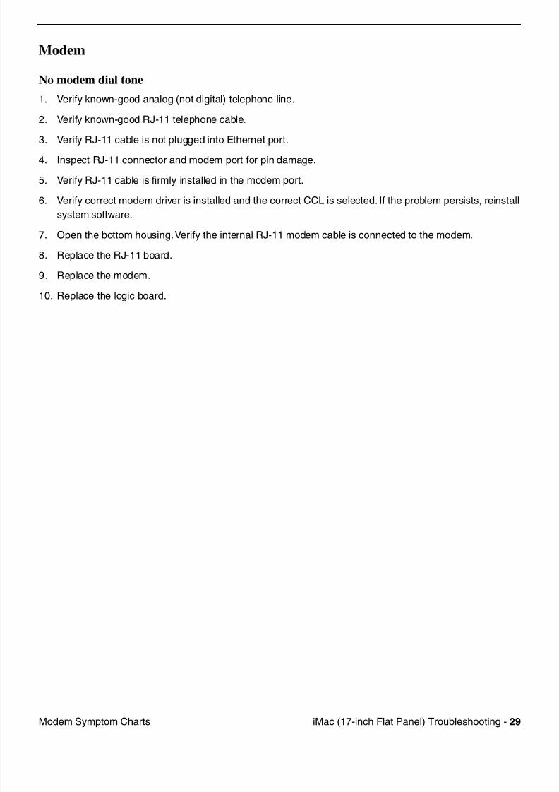
7/28/2019 iMAc 17inc
http://slidepdf.com/reader/full/imac-17inc 131/156
iM (17 i h Fl t P l) T bl h ti 29M d S t Ch t
Modem
No modem dial tone
1. Verify known-good analog (not digital) telephone line.
2. Verify known-good RJ-11 telephone cable.
3. Verify RJ-11 cable is not plugged into Ethernet port.
4. Inspect RJ-11 connector and modem port for pin damage.
5. Verify RJ-11 cable is firmly installed in the modem port.
6. Verify correct modem driver is installed and the correct CCL is selected. If the problem persists, reinstall
system software.
7. Open the bottom housing. Verify the internal RJ-11 modem cable is connected to the modem.
8. Replace the RJ-11 board.
9. Replace the modem.
10. Replace the logic board.
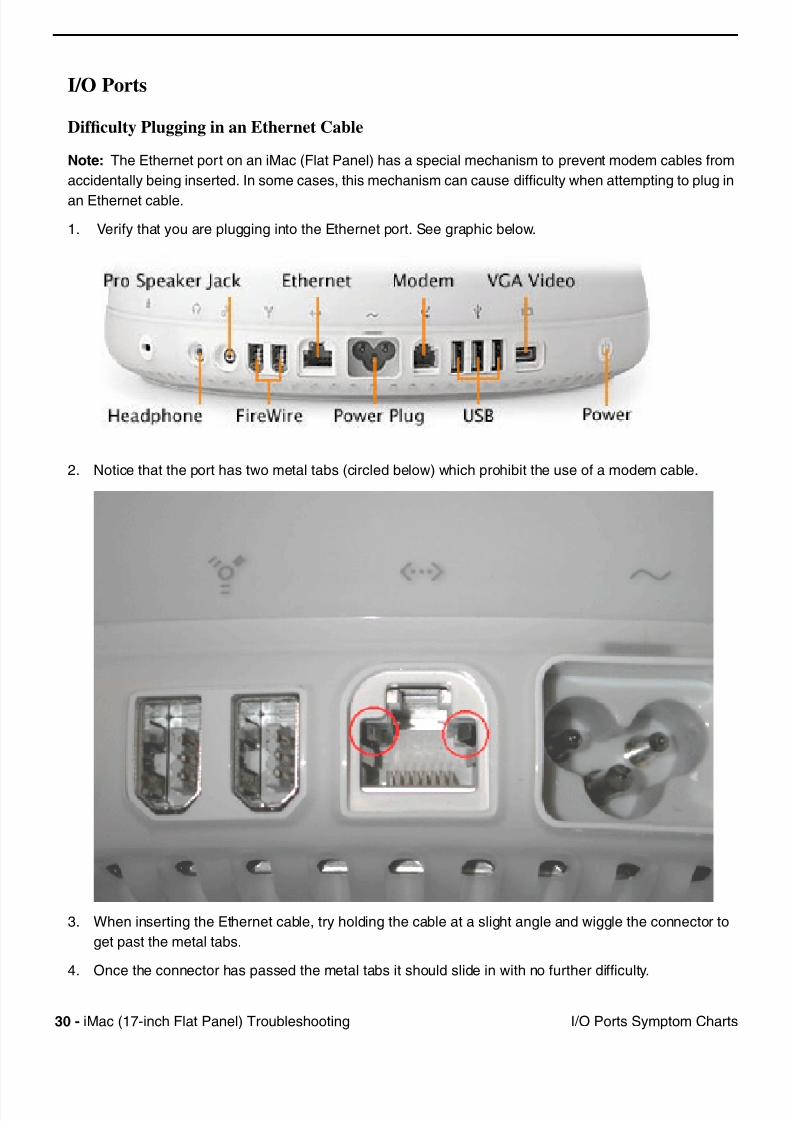
7/28/2019 iMAc 17inc
http://slidepdf.com/reader/full/imac-17inc 132/156
30 iM (17 i h Fl t P l) T bl h ti I/O P t S t Ch t
I/O Ports
Difficulty Plugging in an Ethernet Cable
Note: The Ethernet port on an iMac (Flat Panel) has a special mechanism to prevent modem cables from
accidentally being inserted. In some cases, this mechanism can cause difficulty when attempting to plug in
an Ethernet cable.
1. Verify that you are plugging into the Ethernet port. See graphic below.
2. Notice that the port has two metal tabs (circled below) which prohibit the use of a modem cable.
3. When inserting the Ethernet cable, try holding the cable at a slight angle and wiggle the connector to
get past the metal tabs.
4. Once the connector has passed the metal tabs it should slide in with no further difficulty.

7/28/2019 iMAc 17inc
http://slidepdf.com/reader/full/imac-17inc 133/156
iM (17 i h Fl t P l) T bl h ti 31USB P i ti P bl S t Ch t
USB Printing Problems
iMac cannot print to attached known-good printer.
1. Verify that the printer is Macintosh compatible.
2. Verify that you have setup the printer correctly in OS X.
3. Reinstall the printer driver.
4. Switch the printer to another USB port.
5. Replace the printer interface cable.
6. System software is corrupted. Reinstall the system software.
7. Replace the logic board.
7/28/2019 iMAc 17inc
http://slidepdf.com/reader/full/imac-17inc 134/156
© 2002 Apple Computer Inc Al l rights reserved
Service Source
Upgrades
iMac (17-inch Flat Panel)
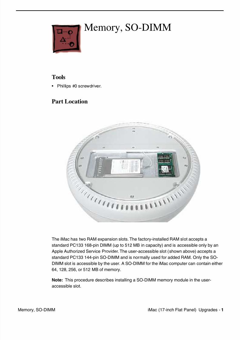
7/28/2019 iMAc 17inc
http://slidepdf.com/reader/full/imac-17inc 135/156
iM (17 i h Fl t P l) U d 1M SO DIMM
Memory, SO-DIMM
Tools
• Phillips #0 screwdriver.
Part Location
The iMac has two RAM expansion slots. The factory-installed RAM slot accepts astandard PC133 168-pin DIMM (up to 512 MB in capacity) and is accessible only by an
Apple Authorized Service Provider. The user-accessible slot (shown above) accepts a
standard PC133 144-pin SO-DIMM and is normally used for added RAM. Only the SO-
DIMM slot is accessible by the user. A SO-DIMM for the iMac computer can contain either
64, 128, 256, or 512 MB of memory.
Note: This procedure describes installing a SO-DIMM memory module in the user-
accessible slot.
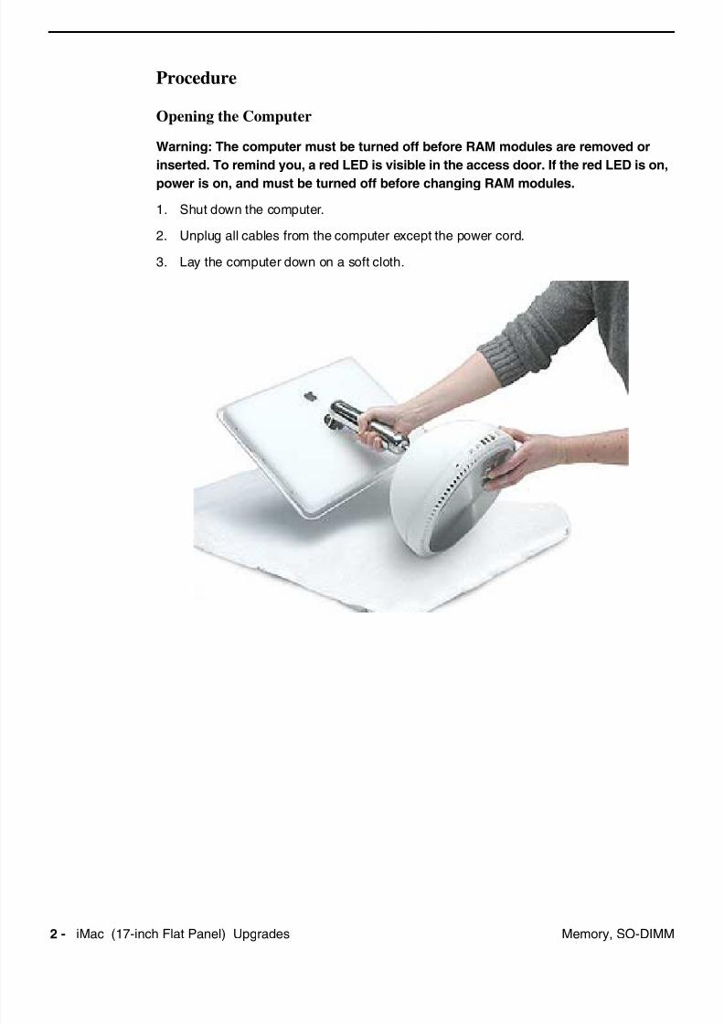
7/28/2019 iMAc 17inc
http://slidepdf.com/reader/full/imac-17inc 136/156
2 iM (17 i h Fl t P l) U d M SO DIMM
Procedure
Opening the Computer
Warning: The computer must be turned off before RAM modules are removed or
inserted. To remind you, a red LED is visible in the access door. If the red LED is on,
power is on, and must be turned off before changing RAM modules.
1. Shut down the computer.
2. Unplug all cables from the computer except the power cord.
3. Lay the computer down on a soft cloth.
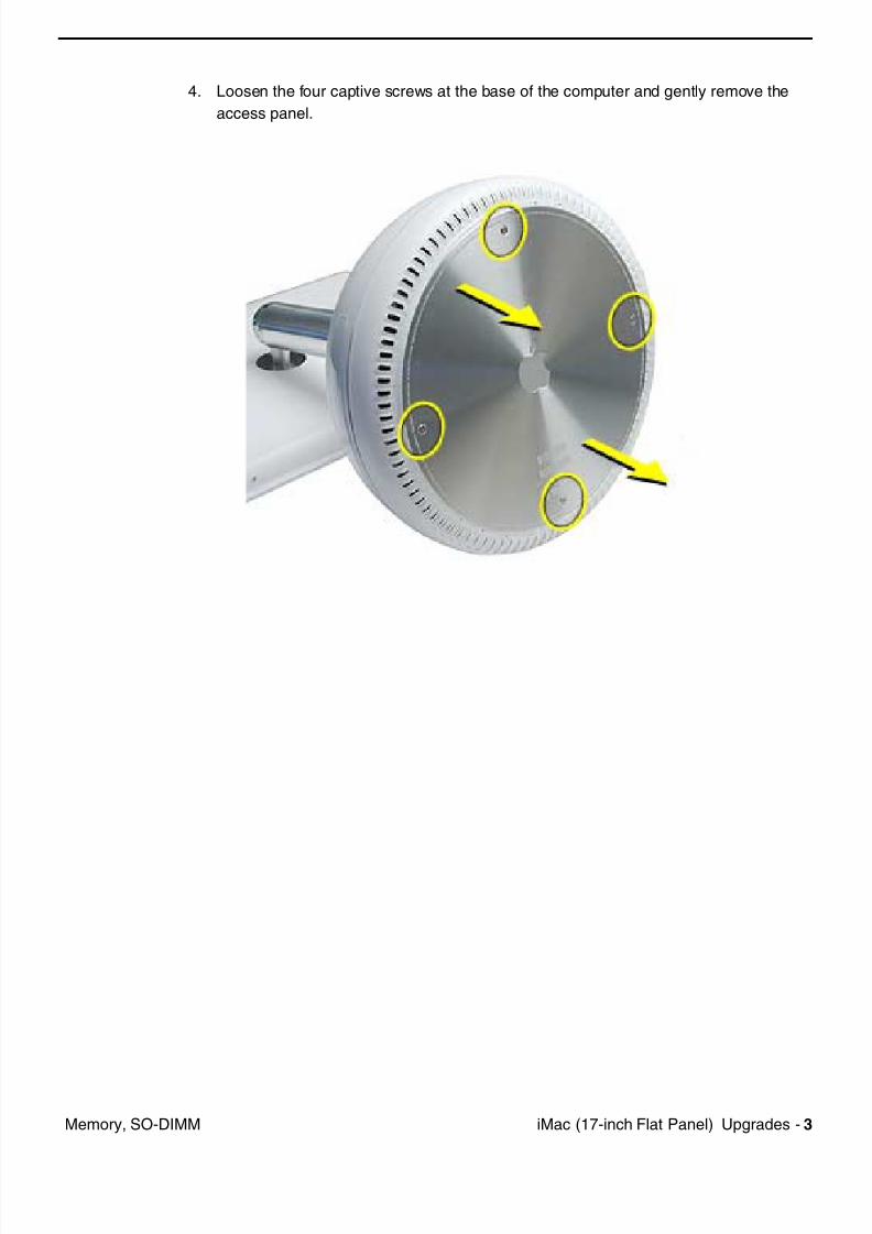
7/28/2019 iMAc 17inc
http://slidepdf.com/reader/full/imac-17inc 137/156
iM (17 i h Fl t P l) U d 3M SO DIMM
4. Loosen the four captive screws at the base of the computer and gently remove the
access panel.
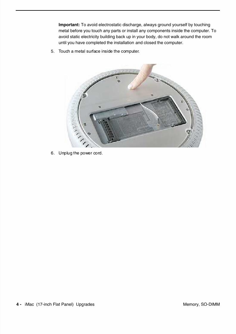
7/28/2019 iMAc 17inc
http://slidepdf.com/reader/full/imac-17inc 138/156
4 iM (17 i h Fl t P l) U d M SO DIMM
Important: To avoid electrostatic discharge, always ground yourself by touching
metal before you touch any parts or install any components inside the computer. To
avoid static electricity building back up in your body, do not walk around the room
until you have completed the installation and closed the computer.
5. Touch a metal surface inside the computer.
6. Unplug the power cord.
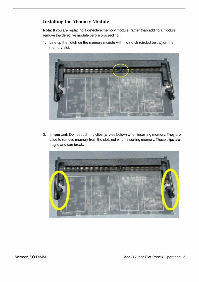
7/28/2019 iMAc 17inc
http://slidepdf.com/reader/full/imac-17inc 139/156
iM (17 i h Fl t P l) U d 5M SO DIMM
Installing the Memory Module
Note: If you are replacing a defective memory module, rather than adding a module,
remove the defective module before proceeding.
1. Line up the notch on the memory module with the notch (circled below) on the
memory slot.
2. Important: Do not push the clips (circled below) when inserting memory. They are
used to remove memory from the slot, not when inserting memory. These clips are
fragile and can break.
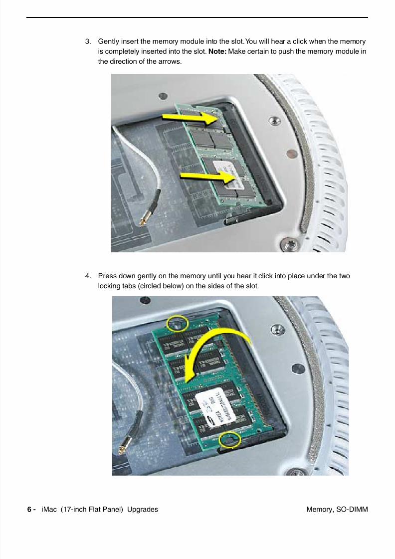
7/28/2019 iMAc 17inc
http://slidepdf.com/reader/full/imac-17inc 140/156
6 iM (17 i h Fl t P l) U d M SO DIMM
3. Gently insert the memory module into the slot. You will hear a click when the memory
is completely inserted into the slot. Note: Make certain to push the memory module in
the direction of the arrows.
4. Press down gently on the memory until you hear it click into place under the two
locking tabs (circled below) on the sides of the slot.
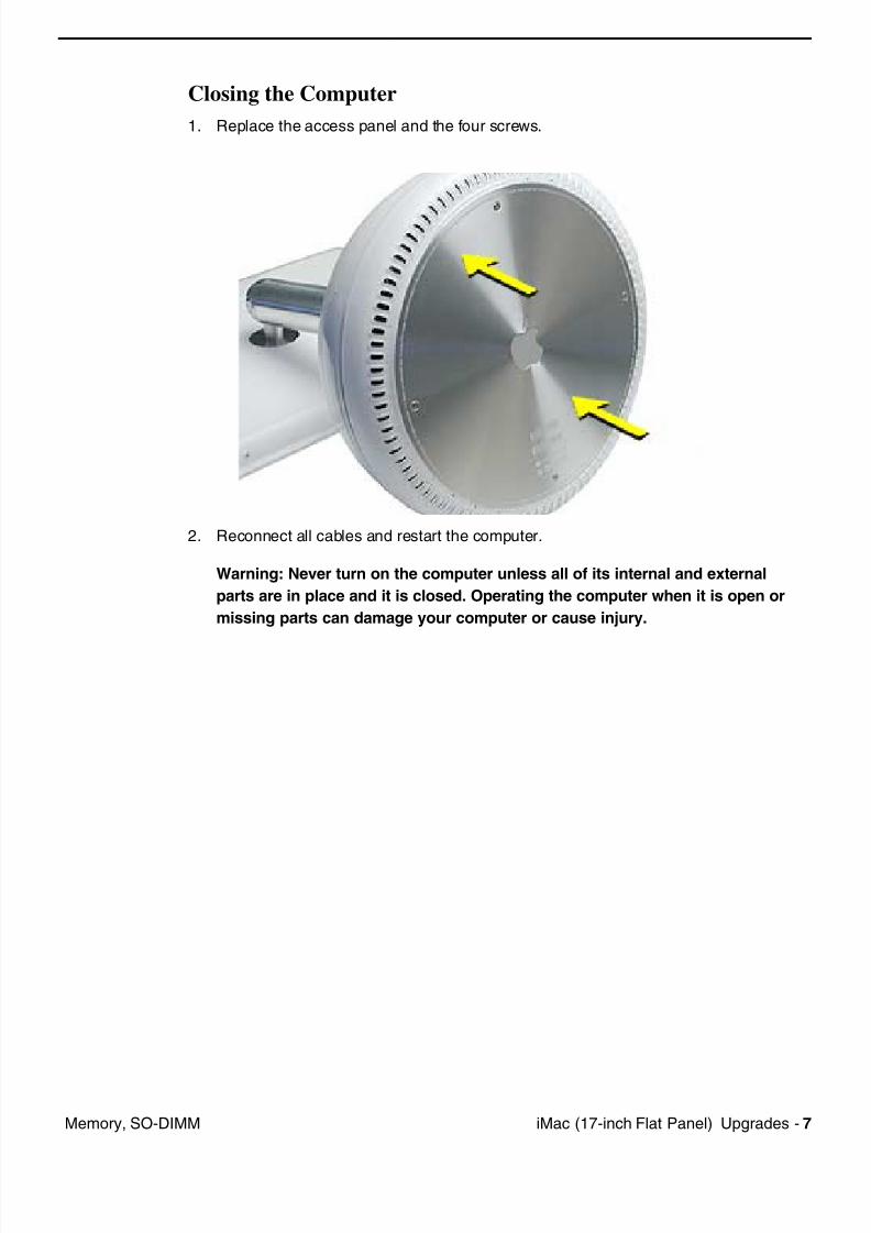
7/28/2019 iMAc 17inc
http://slidepdf.com/reader/full/imac-17inc 141/156
iM (17 i h Fl t P l) U d 7M SO DIMM
Closing the Computer
1. Replace the access panel and the four screws.
2. Reconnect all cables and restart the computer.
Warning: Never turn on the computer unless all of its internal and external
parts are in place and it is closed. Operating the computer when it is open or
missing parts can damage your computer or cause injury.

7/28/2019 iMAc 17inc
http://slidepdf.com/reader/full/imac-17inc 142/156
8 iM (17 i h Fl t P l) U d Ai P t C d
AirPort Card
Tools
• Phillips #0 screwdriver to remove the user access panel.
Part Location
Note: Written and video instructions covering customer-insatiable parts are available athttp://www.info.apple.com/installparts/.
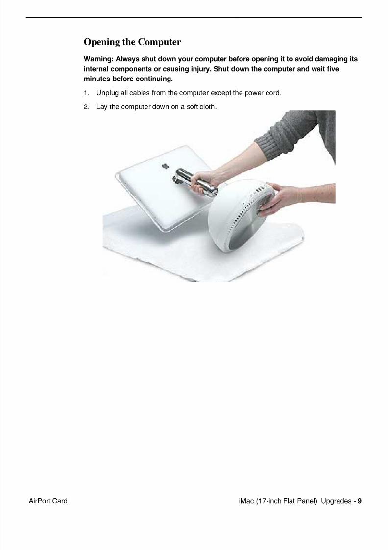
7/28/2019 iMAc 17inc
http://slidepdf.com/reader/full/imac-17inc 143/156
iM (17 i h Fl t P l) U d 9Ai P t C d
Opening the Computer
Warning: Always shut down your computer before opening it to avoid damaging its
internal components or causing injury. Shut down the computer and wait five
minutes before continuing.
1. Unplug all cables from the computer except the power cord.2. Lay the computer down on a soft cloth.
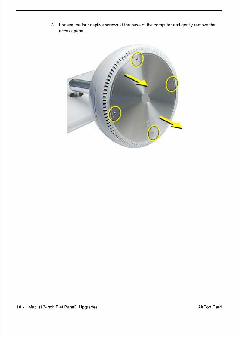
7/28/2019 iMAc 17inc
http://slidepdf.com/reader/full/imac-17inc 144/156
10 iM (17 i h Fl t P l) U d Ai P t C d
3. Loosen the four captive screws at the base of the computer and gently remove the
access panel.
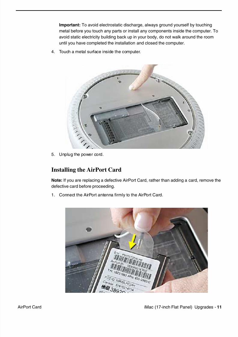
7/28/2019 iMAc 17inc
http://slidepdf.com/reader/full/imac-17inc 145/156
iM (17 i h Fl t P l) U d 11Ai P t C d
Important: To avoid electrostatic discharge, always ground yourself by touching
metal before you touch any parts or install any components inside the computer. To
avoid static electricity building back up in your body, do not walk around the room
until you have completed the installation and closed the computer.
4. Touch a metal surface inside the computer.
5. Unplug the power cord.
Installing the AirPort Card
Note: If you are replacing a defective AirPort Card, rather than adding a card, remove the
defective card before proceeding.
1. Connect the AirPort antenna firmly to the AirPort Card.
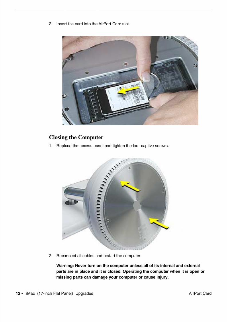
7/28/2019 iMAc 17inc
http://slidepdf.com/reader/full/imac-17inc 146/156
12 iM (17 i h Fl t P l) U d Ai P t C d
2. Insert the card into the AirPort Card slot.
Closing the Computer
1. Replace the access panel and tighten the four captive screws.
2. Reconnect all cables and restart the computer.
Warning: Never turn on the computer unless all of its internal and external
parts are in place and it is closed. Operating the computer when it is open or
missing parts can damage your computer or cause injury.
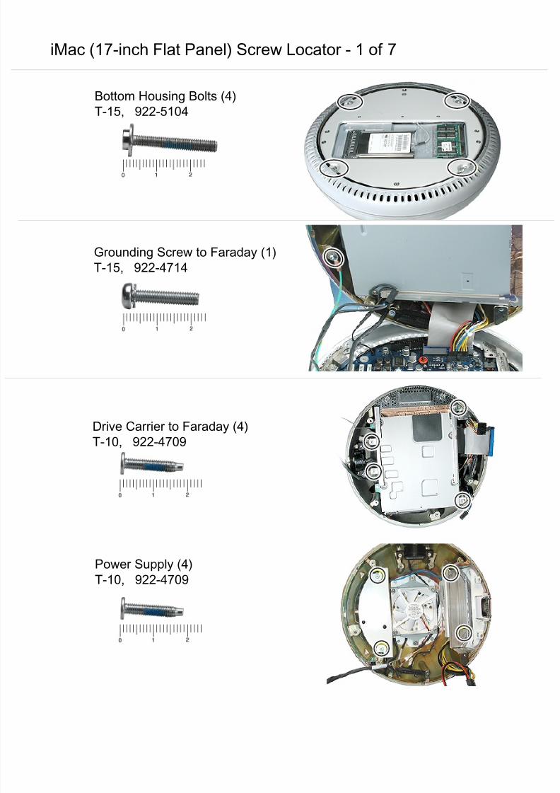
7/28/2019 iMAc 17inc
http://slidepdf.com/reader/full/imac-17inc 147/156
iMac (17-inch Flat Panel) Screw Locator - 1 of 7
Bottom Housing Bolts (4)
T-15, 922-5104
Grounding Screw to Faraday (1)
T-15, 922-4714
Drive Carrier to Faraday (4)
T-10, 922-4709
Power Supply (4)
T-10, 922-4709
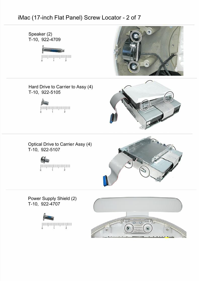
7/28/2019 iMAc 17inc
http://slidepdf.com/reader/full/imac-17inc 148/156
iMac (17-inch Flat Panel) Screw Locator - 2 of 7
Speaker (2)
T-10, 922-4709
Hard Drive to Carrier to Assy (4)
T-10, 922-5105
Optical Drive to Carrier Assy (4)
T-10, 922-5107
Power Supply Shield (2)T-10, 922-4707
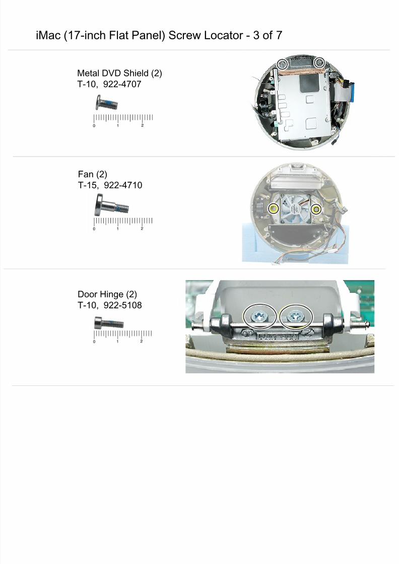
7/28/2019 iMAc 17inc
http://slidepdf.com/reader/full/imac-17inc 149/156
iMac (17-inch Flat Panel) Screw Locator - 3 of 7
Metal DVD Shield (2)
T-10, 922-4707
Fan (2)
T-15, 922-4710
Door Hinge (2)T-10, 922-5108
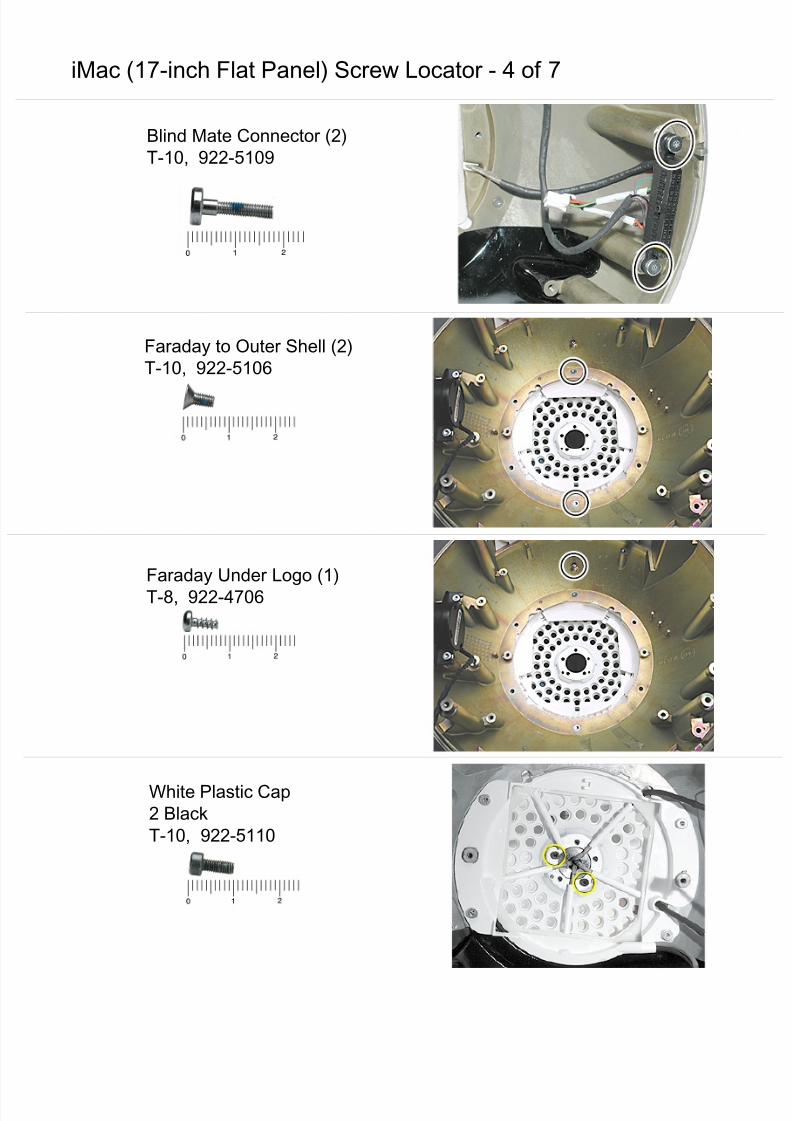
7/28/2019 iMAc 17inc
http://slidepdf.com/reader/full/imac-17inc 150/156
iMac (17-inch Flat Panel) Screw Locator - 4 of 7
Blind Mate Connector (2)
T-10, 922-5109
Faraday to Outer Shell (2)
T-10, 922-5106
Faraday Under Logo (1)
T-8, 922-4706
White Plastic Cap2 Black
T-10, 922-5110
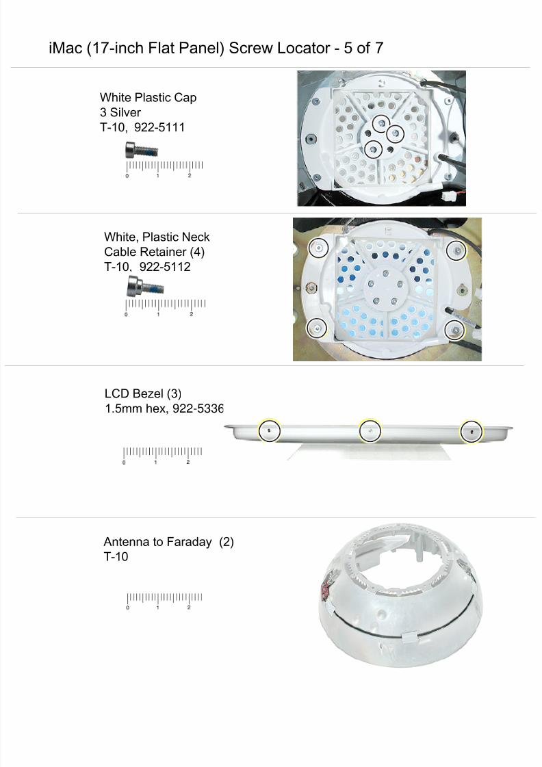
7/28/2019 iMAc 17inc
http://slidepdf.com/reader/full/imac-17inc 151/156
iMac (17-inch Flat Panel) Screw Locator - 5 of 7
White, Plastic Neck
Cable Retainer (4)
T-10, 922-5112
LCD Bezel (3)
1.5mm hex, 922-5336
Antenna to Faraday (2)T-10
White Plastic Cap
3 Silver
T-10, 922-5111
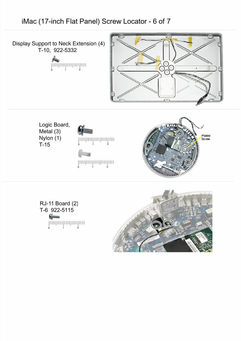
7/28/2019 iMAc 17inc
http://slidepdf.com/reader/full/imac-17inc 152/156
iMac (17-inch Flat Panel) Screw Locator - 6 of 7
Display Support to Neck Extension (4)
T-10, 922-5332
Logic Board,
Metal (3)
Nylon (1)
T-15
RJ-11 Board (2)
T-6 922-5115
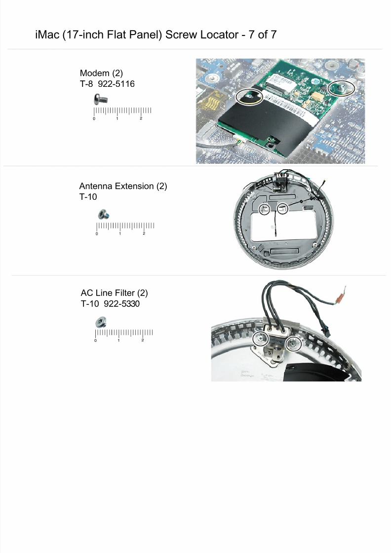
7/28/2019 iMAc 17inc
http://slidepdf.com/reader/full/imac-17inc 153/156
iMac (17-inch Flat Panel) Screw Locator - 7 of 7
Modem (2)
T-8 922-5116
AC Line Filter (2)T-10 922-5330
Antenna Extension (2)
T-10
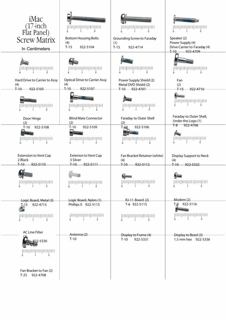
7/28/2019 iMAc 17inc
http://slidepdf.com/reader/full/imac-17inc 154/156
Bottom Housing Bolts
(4)
T-15 922-5104
Blind Mate Connector
(2)
T-10 922-5109
Fan
(2)
T-15 922-4710
Extension to Vent Cap
2 Black
T-10 922-5110
Extenion to Vent Cap
3 Silver
T-10 922-5111
Door Hinge
(2)
T-10 922-5108
Faraday to Outer Shell,
Under the Logo (1)
T-8 922-4706
Faraday to Outer Shell
(2)
T-10 922-5106
Grounding Screw to Faraday
(1)
T-15 922-4714
Hard Drive to Carrier to Assy
(4)
T-10 922-5105
Speaker (2)
Power Supply (4)
Drive Carrier to Faraday (4)
T-10 922-4709
Display Support to Neck
(4)
T-10 922-5332
Power Supply Shield (2)
Metal DVD Shield (2)
T-10 922-4707
Logic Board, Nylon (1)
Phillips 0 922-5113Logic Board, Metal (3)
T-15 922-4715
Modem (2)
T-8 922-5116
Optical Drive to Carrier Assy
(4)
T-10 922-5107
RJ-11 Board (2)
T-6 922-5115
Fan Bracket Retainer (white)
(4)
T-10 922-5112
iMac(17-inch
Flat Panel)Screw Matrix
In Centimeters
AC Line Filter
(2)
T-10 922-5330
Antenna (2)
T-10Display to Frame (4)
T-10 922-5331
Display to Bezel (3)
1.5 mm hex 922-5336
Fan Bracket to Fan (2)
T-25 922-4708
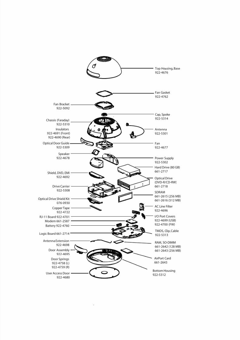
7/28/2019 iMAc 17inc
http://slidepdf.com/reader/full/imac-17inc 155/156
Top Housing, Base
922-4676
Fan Gasket
922-4762
Fan Bracket
922-5092
Cap, Spoke
922-5314Chassis (Faraday)922-5310
Antenna
922-5301
Fan
922-4677
TMDS, Clip, Cable
922-5313
Speaker
922-4678 Power Supply
922-5302
Hard Drive (80 GB)
661-2717
Optical Drive(DVD-R/CD-RW)
661-2718
Shield, DVD, EMI
922-4692
Drive Carrier
922-5308
Optical Drive Shield Kit
076-0930
Copper Tape
922-4722
User Access Door
922-4680
Bottom Housing
922-5312
Door Assembly
922-4695
Antenna Extension
922-4698
SDRAM
661-2615 (256 MB)
661-2616 (512 MB)
Battery 922-4760
Logic Board 661-2714
Modem 661-2587
RJ-11 Board 922-4701
AC Line Filter
922-4696
I/O Port Covers
922-4699 (USB)
922-4700 (FW)
RAM, SO-DIMM
661-2642 (128 MB)
661-2643 (256 MB)
AirPort Card
661-2643
Optical Door Guide
922-5309
Insulators
922-4691 (Front)
922-4690 (Rear)
Door Springs
922-4758 (L)
922-4759 (R)
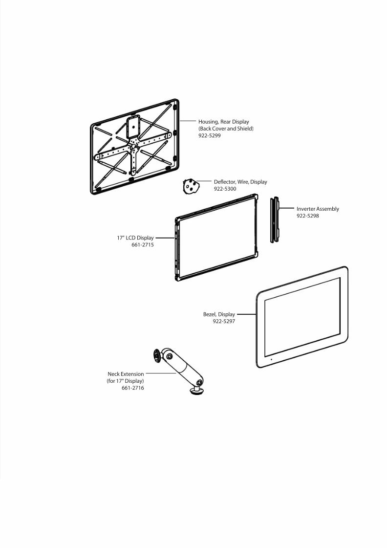
7/28/2019 iMAc 17inc
http://slidepdf.com/reader/full/imac-17inc 156/156
17" LCD Display
661-2715
Housing, Rear Display
(Back Cover and Shield)
922-5299
Inverter Assembly
922-5298
Deflector, Wire, Display
922-5300