Im Pury P Tgmu A (Wt04452 X01)%20 Aug%202005
16
Air-Conditioners For Building Application OUTDOOR UNIT PURY-P-TGMU-A GB F INSTALLATION MANUAL For safe and correct use, please read this installation manual thoroughly before installing the air-conditioner unit. MANUEL D’INSTALLATION Veuillez lire le manuel d’installation en entier avant d’installer ce climatiseur pour éviter tout accident et vous assurer d’une utilisation correcte. For use with R410A
-
Upload
guestab690d -
Category
Business
-
view
677 -
download
2
Transcript of Im Pury P Tgmu A (Wt04452 X01)%20 Aug%202005

Air-Conditioners For Building ApplicationOUTDOOR UNIT
PURY-P-TGMU-A
GB
F
INSTALLATION MANUALFor safe and correct use, please read this installation manual thoroughly before installing the air-conditioner unit.
MANUEL D’INSTALLATIONVeuillez lire le manuel d’installation en entier avant d’installer ce climatiseur pour éviter tout accident et vous assurer d’une utilisation correcte.
For use with R410A
2
(Unit : mm [in])
L1 L2
450 [17-23/32] 450 [17-23/32]
5 [Fig. 5.0.1]
[Fig. 6.0.1]
1 P72 ~ P144
6
7[Fig. 7.1.1]
<B>(2)
C
45°=>
300[11-13/16]
=>1000[39-3/8]
=>
<A>
A
L2=>
L1=>
(1)
A
650
[25-
19/3
2]
325
[2-1
3/16
]
A
Hh
Hh
L1=>
L1=> L2=>
L2=>
<A> <B>
(3)
(4)
E
AA
D D
E
L2* =>
L1* =>
1000 [39-3/8]=>
ED
D
E
A A A A A
L1* => L1=> L1=> L1=> L1=>
L2* =>
E
AA
E
D D
1000 [39-3/8]=>
L2=>
L2=>
900 [35-7/16]=>
E
A
D
A
D1000 [39-3/8]=>1000 [39-3/8]=>
900 [35-7/16]
L2=>
=>
A A
F
A
L1=>L1=>
(5)
B
A
<A> : Top view
<B> : Side view
<C> : When there is little space up to an obstruction
A : Front
B : No restrictions on wall height (left and right)
C : Air outlet guide (Procured at the site)
D : Must be open
E : Wall height (H)
F : No restrictions on wall height
A : M10 anchor bolt procured at the site.
B : Corner is not seated.
<A> <B>
A
A
B
H H’
h
L2=>
L1=>
L1=> L2=>
<C>
8m[26ft]
=<
8m [26ft]=<
40°=<
8m [26ft]=<
8m[26ft]
=<
40°=<2 P168 ~ P234
(Unit : mm [in])
(Unit : m [ft])

3
8 8.2[Fig. 8.2.1]
A : BC controller (standard)
B : BC controller (main)
C : BC controller (sub)
D : indoor unit (06 ~ 54)
E : indoor unit (72, 96)
A (Unit : mm [in])
B (Unit : mm [in])
a, b, c, d, e, j, k (Unit : mm [in])
Å Outdoor modelP72P96P108P126P144P168P192P204P216P234
ı High press. Sideø15.88 [5/8]ø19.05 [3/4]ø19.05 [3/4]ø19.05 [3/4]ø22.2 [7/8]ø22.2 [7/8]ø22.2 [7/8]
ø28.58 [1-1/8] (or ø25.4 [1])ø28.58 [1-1/8] (or ø25.4 [1])ø28.58 [1-1/8] (or ø25.4 [1])
Ç Low press. Sideø19.05 [3/4]ø22.2 [7/8]ø22.2 [7/8]
ø28.58 [1-1/8]ø28.58 [1-1/8]ø28.58 [1-1/8]ø28.58 [1-1/8]ø28.58 [1-1/8]ø28.58 [1-1/8]ø28.58 [1-1/8]
Î Total capacity of indoor units~ 54
55 ~ 72
‰ Liquid lineø9.52 [3/8]ø9.52 [3/8]
Ï Gas lineø15.88 [5/8]ø19.05 [3/4]
Ô Model number06,08,12,15,18
24,27,30,36,48,547296
‰ Liquid lineø6.35 [1/4]ø9.52 [3/8]ø9.52 [3/8]ø9.52 [3/8]
Ï Gas lineø12.7 [1/2]
ø15.88 [5/8]ø19.05 [3/4]ø22.2 [7/8]
C, D (Unit : mm [in])
~ 7273 ~ 108109 ~ 126
Ì High press.gas pipe
ø15.88 [5/8]ø19.05 [3/4]ø19.05 [3/4]
¬ Liquid pipe
ø9.52 [3/8]ø9.52 [3/8]ø12.7 [1/2]
Ó Low press.gas pipe
ø19.05 [3/4]ø22.2 [7/8]
ø28.58 [1-1/8]
f, g, h, i (Unit : mm [in])
Ô Model number
7296
‰ Liquid line Ï Gas linef
ø9.52 [3/8]ø9.52 [3/8]
hø19.05 [3/4]ø22.2 [7/8]
gø9.52 [3/8]ø9.52 [3/8]
iø15.88 [5/8]ø15.88 [5/8]
[Fig. 9.2.2]
9.29[Fig. 9.2.1]
A
B1
3
<A> [Ball valve (Low press. side/flanged type)] <B> [Ball valve(High press. side/flared type)]
[Fig. 9.2.3]
A : Close-packed packing
B : Hollow packing
<C> [Ball valve(High press. side/flanged type)]
<D> This figure shows the valvein the fully open state.
A: Valve stem
B: Stopper pin
C: Packing (Accessory)
D: Connecting pipe (Accessory)
E: Open (Operate slowly)
F: Cap
G: Service port
H: Flare nut
I: ø15.88 [5/8] (PURY-P72)ø19.05 [3/4] (PURY-P96 ~ P126)
J: ø19.05 [3/4] (PURY-P72)ø22.2 [7/8] (PURY-P96, P108)ø28.58 [1-1/8] (PURY-P126 ~ P234)
K: Field piping
L: ø22.2 [7/8] (PURY-P144 ~ P192)ø28.58 [1-1/8] (PURY-P204 ~ P234)
(*Note1)
(*Note1)
(*Note1)
B
A
C
C
D
D
D
D
D
D
D
D
D
D
E
A B C
D
D D
No.2
No.2
No.1
No.1
No.3
No.3
No.4
No.4
No.5
No.5
No.6
No.7 No.8
a
a
b
b
c
c
d e
e
fhi
g
kj
f
A
A
B
B
C
D
d
I
E
O S
SO SO
K K
J L
H
G
F
F
E E
D
D
C
C
BB
A
A
[Fig. 8.2.2]
(Unit : mm [in])
4
10
[Fig. 9.4.4]
[Fig. 9.4.3][Fig. 9.4.2]
CAB
D E
[Fig. 9.4.1]
[Fig. 10.2.1]
BA
D
C
E
EE
D
AB
D
F
G
B
<D> Floor (waterproofing)
E
I
B
<C> Outer wall (exposed)
A B
<A> Inner wall (concealed)
A BD
C
<B> Outer wall
F
H
DB
G
<E> Roof pipe shaft
I
A
J
1000[39-3/8]
1000[39-3/8]
<F> Penetrating portion on firelimit and boundary wall
10.2
A BC
L1 L2 L3 M1M2 M1M2 S
TB3 TB7TB1
A : Steel wire B : Piping
C : Asphaltic oily mastic or asphalt
D : Heat insulation material A
E : Outer covering B
A : High press. pipe B : Low press. pipe
C : Electric wire D : Finishing tape
E : Insulator
A : Sleeve B : Heat insulating material
C : Lagging D : Caulking material
E : Band F : Waterproofing laye
G : Sleeve with edge H : Lagging material
I : Mortar or other incombustible caulking
J : Incombustible heat insulation material
A : Power source
B : Transmission line
C : Ground screw
D
C
C
B
B
E
F
G
H
I
JA
LO HI
LO HI
B
A
K
J
L
H
M
C
D
EN
OF
G
I
[Fig. 9.3.1]
[Fig. 9.3.3]
[Fig. 9.3.2]
9.3
A
A : Nitrogen gas
B : To indoor unit
C : System analyzer
D : Lo knob
E : Hi knob
F : Ball valve
G : Low press. pipe
H : High press. pipe
I : Outdoor unit
J : Service port
A : System analyzer
B : Lo knob
C : Hi knob
D : Ball valve
E : Low press. pipe
F : High press. pipe
G : Service port
H : Three-way joint
I : Valve
J : Valve
K : R410A cylinder
L : Scale
M : Vacuum pump
N : To indoor unit
O : Outdoor unit
A : Syphon pipe
B In case of the cylinder having no syphon pipe.
9.4
(Unit : mm [in])

5
[Fig. 10.3.2]
[Fig. 10.3.1]
A : Group 1
B : Group 4
C : Group 5
D : Shielded wire
E : Sub remotecontroller
( ): Address
[Fig. 10.3.3]
<A> Change the jumper connectorfrom CN41 to CN40
<B> SW2-1:ON
<C> Keep the jumper connector onCN41
<B> SW2-1:ON
<A> Change the jumper connectorfrom CN41 to CN40
<B> SW2-1:ON
<C> Keep the jumper connector onCN41
<B> SW2-1:ON
A
B
C
E
D
M1 M2M1 M2 STB7
TB3
IC
(51)
M1 M2 STB5
RC
(01)
IC
M1 M2 STB5
(03)
IC
M1 M2 STB5
(02)
IC
M1 M2 STB5
(04)
IC
M1 M2 STB5
(05)
IC
M1 M2 STB5
(07)
IC
M1 M2 STB5
(06)
L2
L1
(101)
RC
(105)
RC
(104)
RC
(155)
OC
M1 M2M1 M2 STB7
TB3
(53)
OC
r3
BC
M1 M2 S
(52)
BS
M1 M2 S
(55)
BC
M1 M2 S
(54)
M1M2S
System controller
L3
L6
L4
L5
r2
r4
r1
A B A B A B
A B
CN40
CN40
A
B
C
E
D
M1 M2M1 M2 STB7
TB3
IC
(51)
M1 M2 1 2STB5 TB15
1 2TB15
1 2TB15
1 2TB15
1 2TB15
1 2TB15
1 2TB15
MA
(01)
IC
M1 M2 STB5
(03)
IC
M1 M2 STB5
(02)
IC
M1 M2 STB5
(04)
IC
M1 M2 STB5
(05)
IC
M1 M2 STB5
(07)
IC
M1 M2 STB5
(06)
L2
L1
MA
MA
MA
OC
M1 M2M1 M2 STB7
TB3
CN40
(53)
OC
c1
c4
c3
BC
M1 M2 S
(52)
BS
M1 M2 S
(55)
BC
M1 M2 S
(54)
S
System controller
L3
L6
L4
c3
A BA B A B
M1M2
c1
c1
c2 c2
A B
CN40
M1 M2TB3
RC
N1 N2
IC
M1M2 STB5
IC
M1M2 STB5
RP
A B
A BA B
S
TB2
A B S
TB3
Ground
L4r
1
OC
L7r
1
BC
M1M2 S
RC
IC
M1M2 STB5
IC
M1M2 STB5
L6L5L3L2L1L8
10.3
10.4[Fig. 10.4.1]
A : Switch (breakers for wiring and cur-rent leakage)
B : Outdoor unit
C : BC controller (main)
C' : BC controller (sub)
D : Pull box
E : Indoor unit
F : Breakers for current leakage E E
D
A
E E
AB
C C'
F
F
~208 - 230 V
~208 - 230 V

6
GB
DF
EI
NL
PG
RR
UT
RC
ZS
VS
LH
GP
O
Contents
1. Safety precautions
1.1. Before installation and electric work
s Before installing the unit, make sure you read all the “Safetyprecautions”.
s The “Safety precautions” provide very important points re-garding safety. Make sure you follow them.
Symbols used in the text
Warning:Describes precautions that should be observed to prevent danger of injuryor death to the user.
Caution:Describes precautions that should be observed to prevent damage to theunit.
Symbols used in the illustrations
: Indicates an action that must be avoided.
: Indicates that important instructions must be followed.
: Indicates a part which must be grounded.
: Beware of electric shock. (This symbol is displayed on the main unit label.)
Warning:Carefully read the labels affixed to the main unit.
Warning:• Ask the dealer or an authorized technician to install the air conditioner.
- Improper installation by the user may result in water leakage, electric shock,or fire.
• Install the unit at a place that can withstand its weight.- Inadequate strength may cause the unit to fall down, resulting in injuries.
• Use the specified cables for wiring. Make the connections securely sothat the outside force of the cable is not applied to the terminals.- Inadequate connection and fastening may generate heat and cause a fire.
• Prepare for strong winds and earthquakes and install the unit at the speci-fied place.- Improper installation may cause the unit to topple and result in injury.
• Always use an filter and other accessories specified by Mitsubishi Elec-tric.- Ask an authorized technician to install the accessories. Improper installation
by the user may result in water leakage, electric shock, or fire.• Never repair the unit. If the air conditioner must be repaired, consult the
dealer.- If the unit is repaired improperly, water leakage, electric shock, or fire may
result.• Do not touch the heat exchanger fins.
- Improper handling may result in injury.• If refrigerant gas leaks during installation work, ventilate the room.
- If the refrigerant gas comes into contact with a flame, poisonous gases willbe released.
• Install the air conditioner according to this Installation Manual.- If the unit is installed improperly, water leakage, electric shock, or fire may
result.
• Have all electric work done by a licensed electrician according to “Elec-tric Facility Engineering Standard” and “Interior Wire Regulations”andthe instructions given in this manual and always use a special circuit.- If the power source capacity is inadequate or electric work is performed im-
properly, electric shock and fire may result.• Securely install the outdoor unit terminal cover (panel).
- If the terminal cover (panel) is not installed properly, dust or water may enterthe outdoor unit and fire or electric shock may result.
• When installing and moving the air conditioner to another site, do notcharge it with a refrigerant different from the refrigerant specified on theunit.- If a different refrigerant or air is mixed with the original refrigerant, the refrig-
erant cycle may malfunction and the unit may be damaged.• If the air conditioner is installed in a small room, measures must be taken
to prevent the refrigerant concentration from exceeding the safety limit ifthe refrigerant should leak.- Consult the dealer regarding the appropriate measures to prevent the safety
limit from being exceeded. Should the refrigerant leak and cause the safetylimit to be exceeded, hazards due to lack of oxygen in the room could result.
• When moving and reinstalling the air conditioner, consult the dealer oran authorized technician.- If the air conditioner is installed improperly, water leakage, electric shock, or
fire may result.• After completing installation work, make sure that refrigerant gas is not
leaking.- If the refrigerant gas leaks and is exposed to a fan heater, stove, oven, or
other heat source, it may generate noxious gases.• Do not reconstruct or change the settings of the protection devices.
- If the pressure switch, thermal switch, or other protection device is shortedand operated forcibly, or parts other than those specified by Mitsubishi Elec-tric are used, fire or explosion may result.
• To dispose of this product, consult your dealer.• The installer and system specialist shall secure safety against leakage
according to local regulation or standards.- Following standards may be applicable if local regulation are not available.
• Pay special attention to the place of installation, such as a basement, etc.where refrigeration gas can accumulate, since refrigeration is heavierthan the air.
• With Freshair intake type, the installation site must be carefully chosenbecause outdoor air can directly blow into the room when the thermostatis turned off.- Direct exposure to outdoor air may have harmful effects on people or food.
1.2. Precautions for devices that use R410Arefrigerant
Caution:• Do not use existing refrigerant piping.
- The old refrigerant and refrigerator oil in the existing piping contains a largeamount of chlorine which may cause the refrigerator oil of the new unit todeteriorate.
- R410A is a high-pressure refrigerant and can cause the existing piping toburst.
• Use refrigerant piping made of phosphorus deoxidized copper and cop-per alloy seamless pipes and tubes. In addition, be sure that the innerand outer surfaces of the pipes are clean and free of hazardous sulphur,oxides, dust/dirt, shaving particles, oils, moisture, or any other contami-nant.- Contaminants on the inside of the refrigerant piping may cause the refriger-
ant residual oil to deteriorate.
1. Safety precautions ...................................................................................... 61.1. Before installation and electric work .......................................... 61.2. Precautions for devices that use R410A refrigerant .................. 61.3. Before installation ...................................................................... 71.4. Before installation - electrical work ............................................ 71.5. Before starting the test run ........................................................ 7
2. About the product ....................................................................................... 73. Specifications .............................................................................................. 84. Confirmation of parts attached ................................................................... 85. Space required around unit ........................................................................ 86. Lifting method ............................................................................................. 87. Installation of unit ........................................................................................ 9
7.1. Installation ................................................................................. 98. Refrigerant piping installation ..................................................................... 9
8.1. Caution ...................................................................................... 98.2. Refrigerant piping system .......................................................... 9
9. Additional refrigerant charge ..................................................................... 109.1. Calculation of additional refrigerant charge ............................. 109.2. Precautions concerning piping connection and valve
operation ................................................................................. 109.3. Airtight test, evacuation, and refrigerant charging ................... 119.4. Thermal insulation of refrigerant piping ................................... 12
10. Wiring ........................................................................................................ 1210.1. Caution .................................................................................... 1210.2. Control box and connecting position of wiring ......................... 1210.3. Wiring transmission cables ...................................................... 1210.4. Wiring of main power supply and equipment capacity ............ 14
11. Test run ..................................................................................................... 1511.1. The following phenomena do not represent trouble
(emergency) ............................................................................ 1512. Information on rating plate ........................................................................ 15

7
GB
DF
EI
NL
PG
RR
UT
RC
ZS
VS
LH
GP
O
• Install the power cable so that tension is not applied to the cable.- Tension may cause the cable to break and generate heat and cause a fire.
• Install a leak circuit breaker, as required.- If a leak circuit breaker is not installed, electric shock may result.
• Use power line cables of sufficient current carrying capacity and rating.- Cables that are too small may leak, generate heat, and cause a fire.
• Use only a circuit breaker and fuse of the specified capacity.- A fuse or circuit breaker of a larger capacity, a steel or copper wire may result
in a general unit failure or fire.• Do not wash the air conditioner units.
- Washing them may cause an electric shock.• Be careful that the installation base is not damaged by long use.
- If the damage is left uncorrected, the unit may fall and cause personal injuryor property damage.
• Install the drain piping according to this Installation Manual to ensureproper drainage. Wrap thermal insulation around the pipes to preventcondensation.- Improper drain piping may cause water leakage causing damage to furniture
and other possessions.• Be very careful about transporting the product.
- One person should not carry the product as it weighs more than 20 kg [45LBS].- Some products use PP bands for packaging. Do not use any PP bands as a
means of transportation. It is dangerous.- Do not touch the heat exchanger fins. Doing so may cut your fingers.- When transporting the outdoor unit, support it at the specified positions on
the unit base. Also support the outdoor unit at four points so that it cannotslip sideways.
• Safely dispose of the packing materials.- Packing materials, such as nails and other metal or wooden parts, may cause
stabs or other injuries.- Tear apart and throw away plastic packaging bags so that children will not
play with them. If children play with a plastic bag which was not torn apart,they face the risk of suffocation.
1.5. Before starting the test run Caution:
• Turn on the power at least 12 hours before starting operation.- Starting operation immediately after turning on the main power switch can
result in irreversible damage to internal parts. Keep the power switch turnedon during the operational season.
• Do not touch the switches with wet fingers.- Touching a switch with wet fingers can cause electric shock.
• Do not touch the refrigerant pipes during and immediately after opera-tion.- During and immediately after operation, the refrigerant pipes may be hot or
cold, depending on the condition of the refrigerant flowing through the refrig-erant piping, compressor, and other refrigerant cycle parts. Your hands maysuffer burns or frostbite if you touch the refrigerant pipes.
• Do not operate the air conditioner with the panels and guards removed.- Rotating, hot, or high-voltage parts can cause injuries.
• Do not turn off the power immediately after stopping operation.- Always wait at least five minutes before turning off the power. Otherwise,
water leakage and trouble may occur.• Do not touch the surface of the compressor during servicing.
- If unit is connected to the supply and not running, crank case heater at com-pressor base is operating.
• Store the piping to be used during installation indoors and keep bothends of the piping sealed until just before brazing. (Store elbows andother joints in a plastic bag.)- If dust, dirt, or water enters the refrigerant cycle, deterioration of the oil and
compressor trouble may result.• Use ester oil, ether oil or alkylbenzene (small amount) as the refrigerator
oil to coat flares and flange connections.- The refrigerator oil will degrade if it is mixed with a large amount of mineral
oil.• Use liquid refrigerant to fill the system.
- If gas refrigerant is used to seal the system, the composition of the refriger-ant in the cylinder will change and performance may drop.
• Do not use a refrigerant other than R410A.- If another refrigerant (R22, etc.) is mixed with R410A, the chlorine in the
refrigerant may cause the refrigerator oil to deteriorate.• Use a vacuum pump with a reverse flow check valve.
- The vacuum pump oil may flow back into the refrigerant cycle and cause therefrigerator oil to deteriorate.
• Do not use the following tools that are used with conventional refriger-ants.(Gauge manifold, charge hose, gas leak detector, reverse flow check valve,refrigerant charge base, refrigerant recovery equipment)- If the conventional refrigerant and refrigerator oil are mixed in the R410A,
the refrigerant may deteriorated.- If water is mixed in the R410A, the refrigerator oil may deteriorate.- Since R410A does not contain any chlorine, gas leak detectors for conven-
tional refrigerants will not react to it.• Do not use a charging cylinder.
- Using a charging cylinder may cause the refrigerant to deteriorate.• Be especially careful when managing the tools.
- If dust, dirt, or water gets into the refrigerant cycle, the refrigerant may dete-riorate.
1.3. Before installation Caution:
• Do not install the unit where combustible gas may leak.- If the gas leaks and accumulates around the unit, an explosion may result.
• Do not use the air conditioner where food, pets, plants, precision instru-ments, or artwork are kept.- The quality of the food, etc. may deteriorate.
• Do not use the air conditioner in special environments.- Oil, steam, sulfuric smoke, etc. can significantly reduce the performance of
the air conditioner or damage its parts.• When installing the unit in a hospital, communication station, or similar
place, provide sufficient protection against noise.- Inverter equipment, private power generator, high-frequency medical equip-
ment, or radio communication equipment may cause the air conditioner tooperate erroneously, or fail to operate. On the other hand, the air conditionermay affect such equipment by creating noise that disturbs medical treatmentor image broadcasting.
• Do not install the unit on a structure that may cause leakage.- When the room humidity exceeds 80 % or when the drain pipe is clogged,
condensation may drip from the indoor unit. Perform collective drainage worktogether with the outdoor unit, as required.
1.4. Before installation - electrical work Caution:
• Ground the unit.- Do not connect the ground wire to gas or water pipes, lightning rods, or
telephone ground lines. Improper grounding may result in electric shock.
2. About the product• This unit uses R410A-type refrigerant
• Piping for systems using R410A may be different from that for systems usingconventional refrigerant because the design pressure in systems using R410Ais higher. Refer to Data Book for more information.
• Some of the tools and equipment used for installation with systems that useother types of refrigerant cannot be used with the systems using R410A. Referto Data Book for more information.
• Do not use the existing piping, as it contains chlorine, which is found in con-ventional refrigerating machine oil and refrigerant. This chlorine will deterioratethe refrigerant machine oil in the new equipment. The existing piping must notbe used as the design pressure in systems using R410A is higher than that inthe systems using other types of refrigerant and the existing pipes may burst.

8
GB
DF
EI
NL
PG
RR
UT
RC
ZS
VS
LH
GP
O
3. Specifications
ModelNoise level (50/60 Hz)External static pressure
Cooling mode: – 5 °CDB ~ 43 °CDB [23 °FDB ~ 109 °FDB] (0 °CDB ~ 43 °CDB [32 °FDB ~ 109 °FDB] with outdoor unit at lower position)Heating mode: – 20 °CWB ~ 15.5 °CWB [– 4 °FWB ~ 60 °FWB]Cooling mode: 21 °CDB ~ 43 °CDB [70 °FDB ~ 109 °FDB]Heating mode: – 12.5 °CWB ~ 20 °CWB [10 °FWB ~ 68 °FWB]
5. Space required around unit
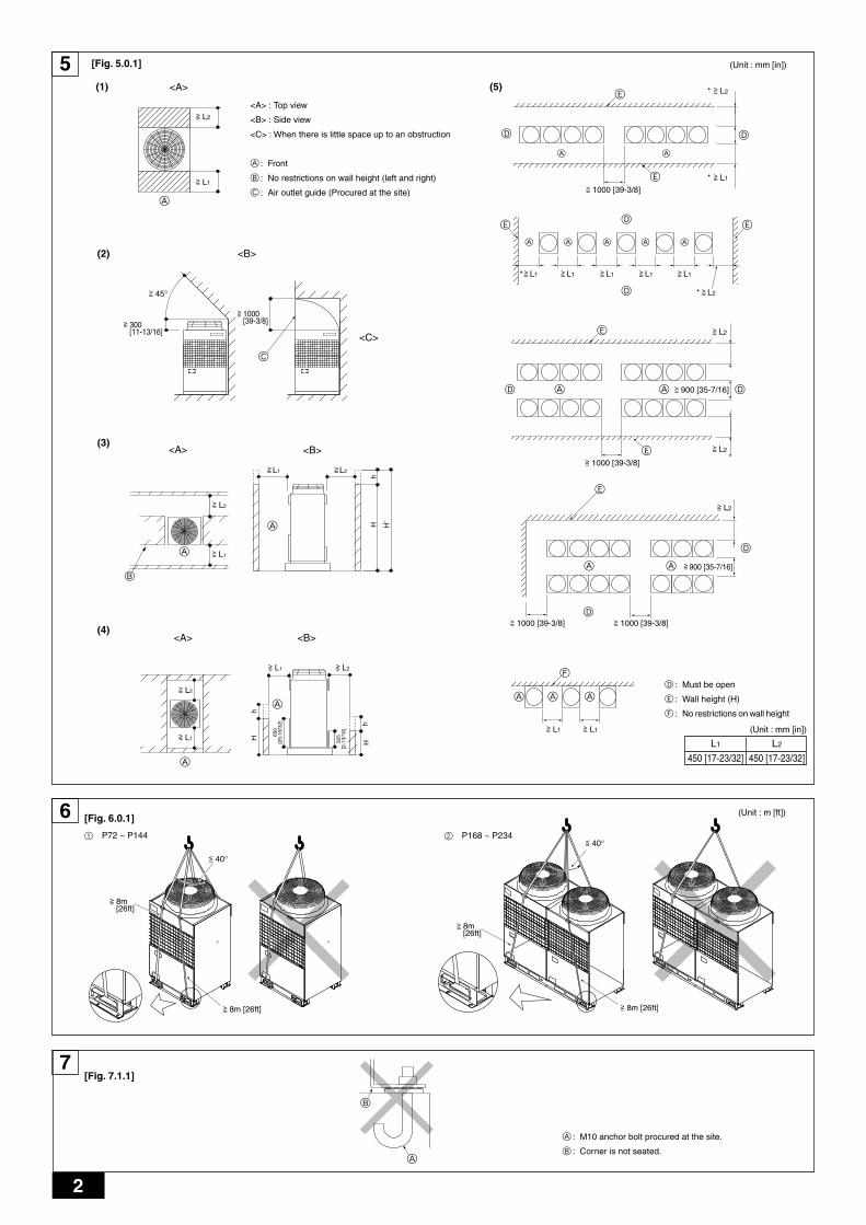
[Fig. 5.0.1] (P.2)
<A> Top view <B> Side view
<C> When there is little space up to an obstruction
A Front B No restrictions on wall height (left and right)
C Air outlet guide (Procured at the site) D Must be open
E Wall height (H) F No restrictions on wall height
(Unit : mm [in])
L1 L2
450 [17-23/32] 450 [17-23/32]
(1) Basic space required
(2) When there is an obstruction above the unit
(3) When inlet air enters from right and left sides of unit
• Wall heights “H” of the front and the back sides shall be within total height ofunit.
• When wall height “H” exceeds total height of unit, add “h” dimension to L1 andL2 of the Fig. 5.0.1.
“h” = wall height “H'” – total height of unit
(4) When unit is surrounded by walls
Note:• Wall heights “H” of the front and the back sides shall be lower than either
the front or the back panel.• If the panel height is exceeded, add the “h” dimension of the Fig. 5.0.1 to
L1 and L2.
(Unit : mm [in])
L1 L2
450 [17-23/32] 450 [17-23/32]
Example: When the “h” dimension is 100 mm [3-15/16in],the L1 dimension becomes 450 [17-23/32] + 100 [3-15/16] = 550 mm [21-21/32in].
(5) Collective installation and continuous installation
• Space required for collective installation and continuous installation:When installing several units, provide the space between each block consider-ing passage for air and people.
• Open in two directions.
• In case of wall height “H” exceeds total height of unit, add “h” dimension (h =wall height “H'” – total height of unit) to * marked dimension.
• If there is a wall at both the front and the rear of the unit, install up to four units(Every three units in the case of P168 ~ P234) consecutively in the side direc-tion and provide a space of 1000 mm [39-3/8in] or more as inlet space/pas-sage space for each four units (Every three units in the case of P168 ~ P234).
6. Lifting method
[Fig. 6.0.1] (P.2)
Caution:Be very careful to carry product.- Do not have only one person to carry product if it weighs more than 20 kg [46LBS].- PP bands are used to pack some products. Do not use them as a mean for transportation because they are dangerous.- Do not touch heat exchanger fins with your bare hands. Otherwise you may cut your hands.- Tear plastic packaging bag and scrap it so that children cannot play with it. Otherwise plastic packaging bag may suffocate children to death.- When carrying outdoor unit, be sure to support it at four points. Carrying with 3-point support may make outdoor unit unstable, resulting in it falling.
4. Confirmation of parts attached
Total capacityModelQuantityStandard type
Fresh air intaketype
Indoor unit
Operationtemperature
PURY-P7256 dB<A>
1 ~ 15
PURY-P9657 dB<A>
1 ~ 16
PURY-P10860 dB<A>
1 ~ 16
PURY-P12661 dB<A>
1 ~ 20
PURY-P14461 dB<A>
1 ~ 24
0 Pa50 ~150 %
06 ~ 96
ModelNoise level (50/60 Hz)External static pressure
Cooling mode:– 5 °CDB ~ 43 °CDB [23 °FDB ~ 109 °FDB] (0 °CDB ~ 43 °CDB [32 °FDB ~ 109 °FDB] with outdoor unit at lower position)Heating mode: – 20 °CWB ~ 15.5 °CWB [– 4 °FWB ~ 60 °FWB]Cooling mode: 21 °CDB ~ 43 °CDB [70 °FDB ~ 109 °FDB]Heating mode: – 12.5 °CWB ~ 20 °CWB [10 °FWB ~ 68 °FWB]
Total capacityModelQuantityStandard type
Fresh air intaketype
Indoor units
Operationtemperature
PURY-P16861 dB<A>
1 ~ 24
PURY-P19262 dB<A>
1 ~ 24
PURY-P20462 dB<A>
1 ~ 24
PURY-P21662.5 dB<A>
1 ~ 32
PURY-P23463 dB<A>
1 ~ 32
0 Pa50 ~150 %
06 ~ 96
Model
Model
Model
P72 ~ P108P126 ~ P144P168 ~ P234
P72 ~ P108P126 ~ P144P168 ~ P234
P72 ~ P108P126 ~ P144P168 ~ P234
1 Conduit mounting plate (ø53 [2-3/32])-
1pc.1pc.
4 Conduit mounting plate (ø27 [1-3/32])1pc.
--
7 Connecting pipe (Low pressure)1pc.1pc.1pc.
2 Conduit mounting plate (ø46 [1-13/16])-
1pc.1pc.
5 Tappinng screw M42pcs.2pcs.2pcs.
8 Packing (Low press. pipe)1pc.1pc.1pc.
3 Conduit mounting plate (ø33 [1-5/16])1pc.
--
6 Connecting pipe (High pressure)1pc. (Flare)
2pcs. (Flange)1pc. (Flange)
9 Packing (High press. pipe)-
1pc.1pc.
(Unit : mm [in])

9
GB
DF
EI
NL
PG
RR
UT
RC
ZS
VS
LH
GP
O
7. Installation of unit
7.1. Installation[Fig. 7.1.1] (P.2)
A M10 anchor bolt procured at the site. B Corner is not seated.
• Fix unit tightly with bolts so that unit will not fall down due to earthquake or gustof wind.
• Use concrete or angle bracket for foundation of unit.
• Vibration may be transmitted to the installation section and noise and vibrationmay be generated from the floor and walls, depending on the installation con-ditions. Therefore, provide ample vibrationproofing (cushion pads, cushionframe, etc.).
• Be sure that the corners are firmly seated. If the corners are not firmly seated,the installation feet may be bent.
Warning:• Be sure to install unit in a place strong enough to withstand its weight.
Any lack of strength may cause unit to fall down, resulting in a personalinjury.
• Have installation work in order to protect against a strong wind and earth-quake.Any installation deficiency may cause unit to fall down, resulting in apersonal injury.
When building the foundation, give full attention to the floor strength, drain waterdisposal <during operation, drain water flows out of the unit>, and piping and wir-ing routes.
Down piping and down wiring precautionsWhen down piping and down wiring are performed, be sure that foundation andbase work does not block the base through holes. When down piping is performed,make the foundation at least 100 mm [3-15/16in] high so that the piping can passunder the bottom of the unit.
8. Refrigerant piping installationCity Multi R2 Series is constituted by an end branching system in which the refrig-erant piping from outdoor unit is branched at BC controller and connected to eachindoor unit.The connection method adapted is brazing connection for high pressure pipe andlow pressure pipe between outdoor unit and BC controller, and flare connectionbetween BC controller and indoor unit. Brazing connection is employed for jointpipe set and branch pipe set.
Warning:Always use extreme care to prevent the refrigerant gas from leaking whileusing fire or flame. If the refrigerant gas comes into contact with a flamefrom any source, such as a gas stove, it breaks down and generates a poi-sonous gas which can cause gas poisoning. Never weld in an unventilatedroom. Always conduct an inspection for gas leakage after installation of therefrigerant piping has been completed.
8.1. CautionThis unit uses refrigerant R410A. Follow the local regulations on materials andpipe thickness when selecting pipes.
1 Use the following materials for refrigeration piping.• Material: Use refrigerant piping made of phosphorus deoxidized copper.
In addition, be sure that the inner and outer surfaces of the pipes are cleanand free of hazardous sulphur, oxides, dust/dirt, shaving particles, oils,moisture, or any other contaminant.
2 Commercially available piping often contains dust and other materials. Alwaysblow it clean with a dry inert gas.
3 Use care to prevent dust, water or other contaminants from entering the pipingduring installation.
4 Reduce the number of bending portions as much as possible, and make bend-ing radius as big as possible.
5 Always observe the restrictions on the refrigerant piping (such as rated length,the difference between high/low pressures, and piping diameter). Failure to doso can result in equipment failure or a decline in heating/cooling performance.
6 Either a lack or an excess of refrigerant causes the unit to make an emergencystop. Charge the system with an appropriate amount of refrigerant. At such atime, always properly charge the unit. When servicing, always check the notesconcerning pipe length and amount of additional refrigerant at both locations,the refrigerant volume calculation table on the back of the service panel andthe additional refrigerant section on the labels for the combined number ofindoor units.
7 Use liquid refrigerant to fill the system.
8 Never use refrigerant to perform an air purge. Always evacuate using a vacuumpump.
9 Always insulate the piping properly. Insufficient insulation will result in a de-cline in heating/cooling performance, water drops from condensation and othersuch problems.
0 When connecting the refrigerant piping, make sure the ball valve of the out-door unit is completely closed (the factory setting) and do not operate it untilthe refrigerant piping for the outdoor and indoor units has been connected, arefrigerant leakage test has been performed and the evacuation process hasbeen completed.
A Residues in commercially available antioxidants may have adverse effects onthe equipment. Braze only with non-oxide brazing material. The use of otherbrazing material may result in compressor damage.(Refer to item 9.2. for detailed information on pipe connections and valve op-erations.)
B Never perform outdoor unit piping connection work when it is raining.
WarningWhen installing and moving the unit, do not charge it with refrigerant otherthan the refrigerant specified on the unit.- Mixing of a different refrigerant, air, etc. may cause the refrigerant cycle to mal-
function and result in severe damage.
Caution:• Use a vacuum pump with a reverse flow check valve.
- If the vacuum pump does not have a reverse flow check valve, the vacuumpump oil may flow back into the refrigerant cycle and cause deterioration ofthe refrigerator oil and other trouble.
• Do not use the tools shown below used with conventional refrigerant.(Gauge manifold, charge hose, gas leak detector, check valve, refrigerantcharge base, vacuum gauge, refrigerant recovery equipment)- Mixing of conventional refrigerant and refrigerator oil may cause the refrig-
erator oil to deteriorate.- Mixing of water will cause the refrigerator oil to deteriorate.- R410A refrigerant does not contain any chlorine. Therefore, gas leak detec-
tors for conventional refrigerants will not react to it.• Manage the tools more carefully than normal.
- If dust, dirt, or water gets in the refrigerant cycle, the refrigerator oil will dete-riorate.
• Never use existing refrigerant piping.- The large amount of chlorine in conventional refrigerant and refrigerator oil
in the existing piping will cause the new refrigerant to deteriorate.• Store the piping to be used during installation indoors and keep both
ends of the piping sealed until just before brazing.- If dust, dirt, or water gets into the refrigerant cycle, the oil will deteriorate and
the compressor may fail.• Do not use a charging cylinder.
- Using a charging cylinder may cause the refrigerant to deteriorate.• Do not use special detergents for washing piping.
8.2. Refrigerant piping systemConnection Example
[Fig. 8.2.1] [Fig. 8.2.2] (P.3)Å Outdoor model ı High press. side
Ç Low press. side Î Total capacity of indoor units
‰ Liquid line Ï Gas line
Ì High press. gas pipe Ó Low press. gas pipe
¬ Liquid pipe Ô Model number
A BC controller (standard) B BC controller (main)
C BC controller (sub) D Indoor unit (06 ~ 54)
E Indoor unit (72, 96)

10
GB
DF
EI
NL
PG
RR
UT
RC
ZS
VS
LH
GP
O
9. Additional refrigerant chargeAt the time of shipping, the outdoor unit is charged with the refrigerant. As thischarge does not include the amount needed for extended piping, additional charg-ing for each refrigerant line will be required on site. In order that future servicingmay be properly provided, always keep a record of the size and length of eachrefrigerant line and the amount of additional charge by writing it in the space pro-vided on the outdoor unit.
9.1. Calculation of additional refrigerantcharge
• Calculate the amount of additional charge based on the length of the pipingextension and the size of the refrigerant line.
• Use the table to the below as a guide to calculating the amount of additionalcharging and charge the system accordingly.
• If the calculation results in a fraction of less than 0.1 kg [4oz], round up to thenext 0.1 kg [4oz]. For example, if the result of the calculation was 10.62 kg[373.3oz], round the result up to 10.7 kg [376oz].
<Additional Charge>
= + + +
Value of α2
α 2BC controller (standard, main only) 0 kg [0oz]BC controller (sub) connected (one) 1.0 kg [36oz]BC controller (sub) connected (two) 2.0 kg [71oz]
9.2. Precautions concerning piping connec-tion and valve operation
• Conduct piping connection and valve operation accurately.
• Flange type side connecting pipe is assembled in factory before shipment.
1 For brazing to the connecting pipe with flange, remove the connecting pipewith flange from the ball valve, and braze it outside of the unit.
2 During the time when removing the connecting pipe with flange, removethe seal attached on the rear side of this sheet and paste it onto the flangesurface of the ball valve to prevent the entry of dust into the valve.
3 The refrigerant circuit is closed with a round, close-packed packing uponshipment to prevent gas leak between flanges. As no operation can bedone under this state, be sure to replace the packing with the hollow pack-ing attached at the piping connection.
4 At the mounting of the hollow packing, wipe off dust attached on the flangesheet surface and the packing. Coat refrigerating machine oil (Ester oil,ether oil or alkylbenzene [small amount]) onto both surfaces of the pack-ing.
[Fig. 9.2.1] (P.3)A Close-packed packing
B Hollow packing
• After evacuation and refrigerant charge, ensure that the handle is fully open. Ifoperating with the valve closed, abnormal pressure will be imparted to thehigh- or low-pressure side of the refrigerant circuit, giving damage to the com-pressor, four-way valve, etc.
• Determine the amount of additional refrigerant charge by using the formula,and charge refrigerant additionally through the service port after completingpiping connection work.
• After completing work, tighten the service port and cap securely not to gener-ate gas leak.
• Flare machining dimension for systems using R410A is larger than that forsystems using other types of refrigerant in order to increase the air tightness.
• Refer to the table on the below for flare machining dimensions, and follow theregulations set forth by the local authorities. Seal off the opening of the pipewith a closure material (not supplied) to keep small animals from entering thepipe if that is a concern.
flare machining dimension (mm)
Additionalrefrigerantcharge
(kg)
High pressurepipe sizeTotal length ofø25.4 [1]
(m) × 0.31 (kg/m)
(in) × 3.33 (oz/ft)
<Example 1>[Fig. 8.2.1] (P.3)Indoor No. 1: 15 A: ø19.05 [3/4] 40 m [131ft] a: ø6.35 [1/4] 10 m [32ft]
No. 2: 72 B: ø9.52 [3/8] 10 m [32ft] b: ø9.52 [3/8] 5 m [16ft]No. 3: 15 c: ø6.35 [1/4] 10 m [32ft]No. 4: 12 d: ø6.35 [1/4] 10 m [32ft]No. 5: 24 e: ø9.52 [3/8] 10 m [32ft]
The total length of each liquid line is as follows:ø19.05 [3/4]: A = 40 m [131ft]ø9.52 [3/8]: B + b + e = 10 [32] + 5 [16] + 10 [32] = 25 m [80ft]ø6.35 [1/4]: a + c + d = 10 [32] + 10 [32] + 10 [32] = 30 m [96ft]
Therefore,<Calculation example>Additional refrigerant charge
= 40 [131] × 0.16 [1.72] + 25 [80] × 0.06 [0.65]+ 30 [96] × 0.024 [0.26] + 2.0 [71oz] = 10.7 kg [376oz]
<Example 2>[Fig. 8.2.2] (P.3)Indoor No. 1: 15 A: ø22.2 [7/8] 40 m [131ft] a: ø6.35 [1/4] 10 m [32ft]
No. 2: 36 B: ø9.52 [3/8] 10 m [32ft] b: ø9.52 [3/8] 5 m [16ft]No. 3: 15 C: ø12.7 [1/2] 10 m [32ft] c: ø6.35 [1/4] 10 m [32ft]No. 4: 12 D: ø12.7 [1/2] 10 m [32ft] d: ø6.35 [1/4] 10 m [32ft]No. 5: 24 e: ø9.52 [3/8] 10 m [32ft]No. 6: 72 f: ø9.52 [3/8] 10 m [32ft]No. 7: 12 g: ø6.35 [1/4] 5 m [16ft]No. 8: 12 h: ø6.35 [1/4] 5 m [16ft]
The total length of each liquid line is as follows:ø22.2 [7/8]: A = 40 m [131ft]ø12.7 [1/2]: C + D = 10 [32] + 10 [32] = 20 m [64ft]ø9.52 [3/8]: B + b + e + f = 10 [32] + 5 [16] + 10 [32] + 10 [32] = 35 m [112ft]ø6.35 [1/4]: a + c + d + g + h = 10 [32] + 10 [32] + 10 [32] + 5 [16] + 5 [16] = 40 m [128ft]
Therefore,<Calculation example>Additional refrigerant charge
= 40 [131] × 0.23 [2.47] + 20 [64] × 0.12 [1.29] + 35 [112] × 0.06 [0.65]+ 40 [128] × 0.024 [0.26] + 3.0 [106] + 2.0 [71] = 19.7 kg [689oz]
Value of α1
Total capacity of connecting indoor units α 1to Model 30 1.0 kg [36oz]
Models 31 to 60 1.5 kg [53oz]Models 61 to 126 2.0 kg [71oz]Models 127 to 180 2.5 kg [89oz]Models 181 to 234 3.0 kg [106oz]Models 235 to 264 4.0 kg [142oz]Models 265 to 366 5.0 kg [178oz]Models 367 to 468 6.0 kg [212oz]
[Fig. 9.2.2] (P.3)<A> [Ball valve (Low press. side/flanged type)]
<B> [Ball valve (High press. side/flared type)]
<C> [Ball valve (High press. side/flanged type)]
<D>This figure shows the valve in the fully open state.
A Valve stem[Fully closed at the factory, when connecting the piping, when evacuating, andwhen charging additional refrigerant. Open fully after the operations above arecompleted.]
B Stopper pin [Prevents the valve stem from turning 90° or more.]
C Packing (Accessory)[Manufacturer: Nichiasu corporation][Type: T/#1991-NF]
D Connecting pipe (Accessory)[Use packing and securely install this pipe to the valve flange so that gas leakagewill not occur. (Tightening torque:40 N·m [400 kg·cm]) Coat both surfaces of thepacking with refrigerating machine oil. (Ester oil, ether oil or alkylbenzene [smallamount])]
High pressurepipe sizeTotal length ofø22.2 [7/8]
(m) × 0.23 (kg/m)
(in) × 2.47 (oz/ft)
High pressurepipe sizeTotal length ofø19.05 [3/4]
(m) × 0.16 (kg/m)
(in) × 1.72(oz/ft)
High pressurepipe sizeTotal length ofø15.88 [5/8]
(m) × 0.11 (kg/m)
(in) × 1.18 (oz/ft)
+ + + + + α1 + α2
High pressurepipe sizeTotal length ofø12.7 [1/2]
(m) × 0.12 (kg/m)
(in) × 1.29 (oz/ft)
High pressurepipe sizeTotal length ofø9.52 [3/8]
(m) × 0.06 (kg/m)
(in) × 0.65 (oz/ft)
High pressurepipe sizeTotal length ofø6.35 [1/4]
(m) × 0.024 (kg/m)
(in) × 0.26 (oz/ft)
flare nut size (mm)
outer diameter
ø6.35ø9.52ø12.70ø15.88ø19.05
size in inches
1/4"3/8"1/2"5/8"3/4"
dimension AR410A
9.113.216.619.724.0
A
B
outer diameter
ø6.35ø9.52ø12.70ø15.88ø19.05
size in inches
1/4"3/8"1/2"5/8"3/4"
dimension BR410A
17.022.026.029.036.0
At theconditionsbelow:
At theconditionsbelow:
High pressurepipe sizeTotal length ofø28.58 [1-1/8]
(m) × 0.36 (kg/m)
(in) × 3.90 (oz/ft)

11
GB
DF
EI
NL
PG
RR
UT
RC
ZS
VS
LH
GP
O
E Open (Operate slowly)
F Cap, copper packing[Remove the cap and operate the valve stem. Always reinstall the cap after op-eration is completed. (Valve stem cap tightening torque: 23 ~ 27 N·m [230 ~270 kg·cm])]
G Service port[Use this port to evacuate the refrigerant piping and add an additional charge atthe site.Open and close the port using a double-ended wrench.Always reinstall the cap after operation is completed. (Service port cap tighteningtorque: 12 ~ 15 N·m [120 ~ 150 kg·cm])]
H Flare nut[Tightening torque: Refer to the following table.Loosen and tighten this nut using a double-ended wrench.Coat the flare contact surface with refrigerating machine oil (Ester oil, ether oil oralkylbenzene [small amount])]
I ø15.88 [5/8] (PURY-P72)ø19.05 [3/4] (PURY-P96 ~ P126)
J ø19.05 [3/4] (PURY-P72)ø22.2 [7/8] (PURY-P96, P108)ø28.58 [1-1/8] (PURY-P126 ~ P234)
K Field piping
L ø22.2 [7/8] (PURY-P144 ~ P192)ø28.58 [1-1/8] (PURY-P204 ~ P234)
Appropriate tightening torque by torque wrench:
Copper pipe external dia. (mm [in]) Tightening torque (N·m / kg·cm)ø6.35 [1/4] 14 to 18 / 140 to 180ø9.52 [3/8] 35 to 42 / 350 to 420ø12.7 [1/2] 50 to 57.5 / 500 to 575ø15.88 [5/8] 75 to 80 / 750 to 800ø19.05 [3/4] 100 to 140 / 1000 to 1400
Tightening angle standard:
Pipe diameter (mm [in]) Tightening angle (°)ø6.35 [1/4], ø9.52 [3/8] 60 to 90ø12.7 [1/2], ø15.88 [5/8] 30 to 60
ø19.05 [3/4] 20 to 35
[Fig. 9.2.3] (P.3)
Note:If a torque wrench is not available, use the following method as a standard:When you tighten the flare nut with a wrench, you will reach a point wherethe tightening torque will abruptly increase. Turn the flare nut beyond thispoint by the angle shown in the table above.
Caution:• Always remove the connecting pipe from the ball valve and braze it out-
side the unit.- Brazing the connecting pipe while it is installed will heat the ball valve and
cause trouble or gas leakage. The piping, etc. inside the unit may also beburned.
• Use ester oil, ether oil or alkylbenzene (small amount) as the refrigerat-ing machine oil to coat flares and flange connections.- The refrigerating machine oil will degrade if it is mixed with a large amount of
mineral oil.• Keep the ball valve closed until refrigerant charging to the pipes to be
added on site has been completed. Opening the valve before chargingthe refrigerant may result in unit damage.
• Do not use a leak detection additive.
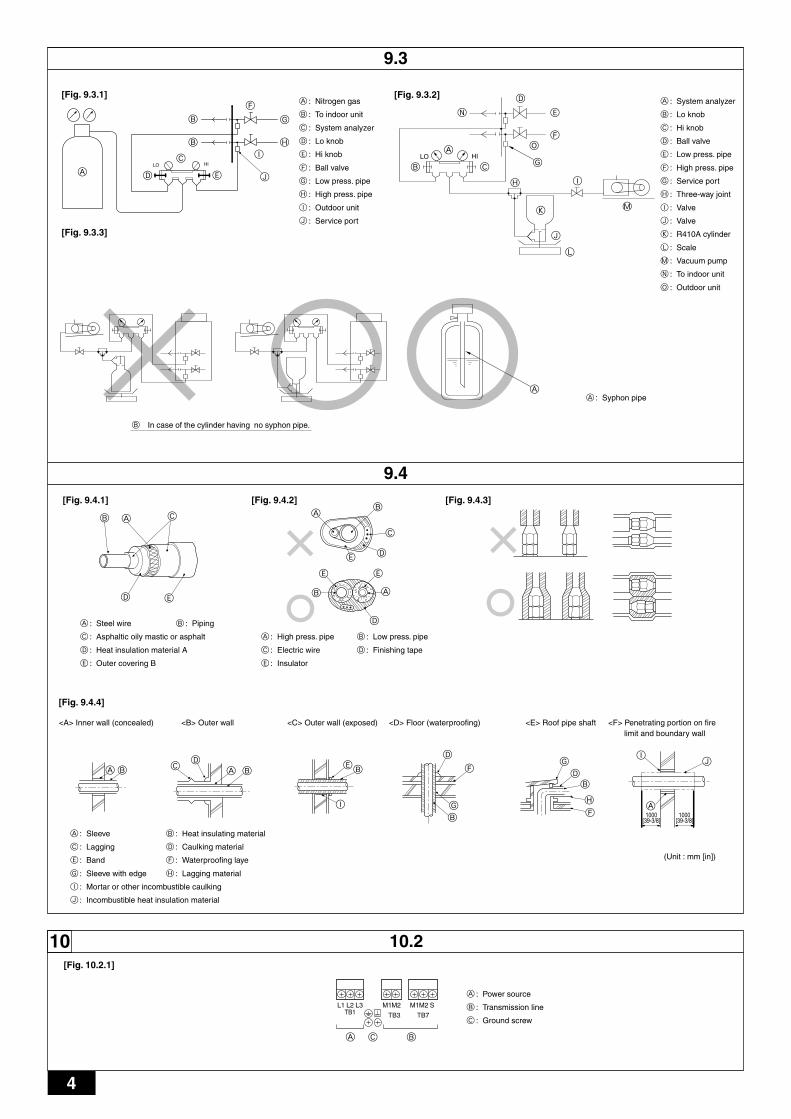
9.3. Airtight test, evacuation, and refrigerantcharging
1 Airtight testPerform with the ball valve of the outdoor unit closed, and pressurize the con-nection piping and the indoor unit from the service port provided on the ballvalve of the outdoor unit. (Always pressurize from both the high press pipe andthe low press pipe service ports.)
[Fig. 9.3.1] (P.4)
A Nitrogen gas B To indoor unit C System analyzer
D Lo knob E Hi knob F Ball valve
G Low press. pipe H High press. pipe I Outdoor unit
J Service port
Observe the following restrictions when conducting an air tightness test to preventnegative effects on the refrigerating machine oil. Also, with nonazeotropic refriger-ant (R410A), gas leakage causes the composition to change and affects perform-ance. Therefore, perform the airtightness test cautiously.
Caution:Only use refrigerant R410A.- The use of other refrigerant such as R22 or R407C, which contains chlorine, will
deteriorate the refrigerating machine oil or cause the compressor to malfunction.
2 EvacuationEvacuate with the ball valve of the outdoor unit closed and evacuate both theconnection piping and the indoor unit from the service port provided on the ballvalve of the outdoor unit using a vacuum pump. (Always evacuate from theservice port of both the high press pipe and the low press pipe.) After thevacuum reaches 650 Pa [abs] [0.0943 psi/5Torr], continue evacuation for atleast one hour or more.* Never perform air purging using refrigerant.
[Fig. 9.3.2] (P.4)
A System analyzer B Lo knob C Hi knob
D Ball valve E Low press. pipe F High press. pipe
G Service port H Three-way joint I Valve
J Valve K R410A cylinder L Scale
M Vacuum pump N To indoor unit O Outdoor unit
Note:• Always add an appropriate amount of refrigerant. Also always seal the
system with liquid refrigerant. Too much or too little refrigerant will causetrouble.
• Use a gauge manifold, charging hose, and other parts for the refrigerantindicated on the unit.
• Use a graviometer. (One that can measure down to 0.1 kg [3oz].)• Use a vacuum pump with a reverse flow check valve.
(Recommended vacuum gauge: ROBINAIR 14830A Thermistor VacuumGauge)Also use a vacuum gauge that reaches 65 Pa [abs] [0.00943 psi / 0.5 Torr]or below after operating for five minutes.
3 Refrigerant ChargingSince the refrigerant used with the unit is nonazerotropic, it must be charged inthe liquid state. Consequently, when charging the unit with refrigerant from acylinder, if the cylinder does not have a syphon pipe, charge the liquid refriger-ant by turning the cylinder upside-down as shown in Fig.9.3.3. If the cylinderhas a syphon pipe like that shown in the picture on the right, the liquid refriger-ant can be charged with the cylinder standing upright. Therefore, give carefulattention to the cylinder specifications. If the unit should be charged with gasrefrigerant, replace all the refrigerant with new refrigerant. Do not use the re-frigerant remaining in the cylinder.
Restriction
• If a flammable gas or air (oxygen) is used as the pressurizationgas, it may catch fire or explode.
• Do not use a refrigerant other than that indicated on the unit.• Sealing with gas from a cylinder will cause the composition of
the refrigerant in the cylinder to change.• Use a pressure gauge, charging hose, and other parts especially
for R410A.• An electric leak detector for R22 cannot detect leaks of R410A.• Do not use a haloid torch. (Leaks cannot be detected.)
Airtight test procedure
1. Nitrogen gas pressurization(1) After pressurizing to the design pressure (4.15 MPa [602 psi]) using nitrogen gas, allow it to
stand for about one day. If the pressure does not drop, airtightness is good.However, if the pressure drops, since the leaking point is unknown, the following bubble testmay also be performed.
(2) After the pressurization described above, spray the flare connection parts, brazed parts, flanges,and other parts that may leak with a bubbling agent (Kyuboflex, etc.) and visually check forbubbles.
(3) After the airtight test, wipe off the bubbling agent.
2. Pressurization using refrigerant gas and nitrogen gas(1) Pressurizing to a gas pressure of approximately 0.2 MPa [29 psi], pressurize to the design
pressure (4.15 MPa [602 psi]) using nitrogen gas.However, do not pressurize at one time. Stop during pressurization and check that the pres-sure does not drop.
(2) Check for gas leaks by checking the flare connection parts, brazed parts, flanges, and otherparts which may leak using an R410A compatible electric leak detector.
(3) This test may be used together the with bubble type gas leak test.

12
GB
DF
EI
NL
PG
RR
UT
RC
ZS
VS
LH
GP
O
[Fig. 9.3.3] (P.4)A Syphon pipe B In case of the cylinder having no syphon pipe.
9.4. Thermal insulation of refrigerant pipingBe sure to give insulation work to refrigerant piping by covering liquid pipe and gaspipe separately with enough thickness heat-resistant polyethylene, so that no gapis observed in the joint between indoor unit and insulating material, and insulatingmaterials themselves. When insulation work is insufficient, there is a possibility ofcondensation drip, etc. Pay special attention to insulation work to ceiling plenum.
[Fig. 9.4.1] (P.4)
A Steel wire B Piping
C Asphaltic oily mastic or asphalt D Heat insulation material A
E Outer covering B
Glass fiber + Steel wire
Adhesive + Heat - resistant polyethylene foam + Adhesive tape
Indoor Vinyl tapeFloor exposed Water-proof hemp cloth + Bronze asphaltOutdoor Water-proof hemp cloth + Zinc plate + Oily paint
Note:• When using polyethylene cover as covering material, asphalt roofing shall
not be required.• No heat insulation must be provided for electric wires.
[Fig. 9.4.2] (P.4)
A High press. pipe B Low press. pipe C Electric wire
D Finishing tape E Insulator
[Fig. 9.4.3] (P.4)
10. Wiring
10.1. Caution1 Follow ordinance of your governmental organization for technical standard re-
lated to electrical equipment, wiring regulations and guidance of each electricpower company.
2 Wiring for control (hereinafter referred to as transmission line) shall be (5 cm ormore [2in or more]) apart from power source wiring so that it is not influencedby electric noise from power source wiring. (Do not insert transmission lineand power source wire in the same conduit.)
3 Be sure to provide designated grounding work to outdoor unit.
4 Give some allowance to wiring for electrical part box of indoor and outdoorunits, because the box is sometimes removed at the time of service work.
5 Never connect the main power source to terminal block of transmission line. Ifconnected, electrical parts will be burnt out.
6 Use 2-core shield cable for transmission line. If transmission lines of differentsystems are wired with the same multiplecore cable, the resultant poor trans-mitting and receiving will cause erroneous operations.
7 Only the transmission line specified should be connected to the terminal blockfor outdoor unit transmission.(Transmission line to be connected with indoor unit : Terminal block TB3 fortransmission line, Other : Terminal block TB7 for centralized control)Erroneous connection does not allow the system to operate.
8 In the case of connecting with an upper class controller or to conduct groupoperation in different refrigerant systems, the control line for transmission isrequired between the outdoor units.Connect this control line between the terminal blocks for centralized control.(2-wire line with no polarity)When conducting group operation in different refrigerant systems without con-necting to the upper class controller, replace the insertion of the short circuitconnector from CN41 of one outdoor unit to CN40.
9 Group is set by operating the remote controller.
10.2. Control box and connecting position ofwiring
1. Connect the indoor unit transmission line to transmission terminal block (TB3),or connect the wiring between outdoor units or the wiring with the central controlsystem to the central control terminal block (TB7).When using shielded wiring, connect shield ground of the indoor unit transmis-sion line to the ground screw ( ) and connect shield ground of the line betweenoutdoor units and the central control system transmission line to the shield (S)terminal of the central control terminal block (TB7) shield (S) terminal. In addi-tion, in the case of outdoor units whose power supply connector CN41 has beenreplaced by CN40, the shield terminal (S) of terminal block (TB7) of the centralcontrol system should also be connected to the ground screw ( ).
Fix the wiring securely in place with the cable strap at the bottom of the termi-nal block so that the external force if not applied to the terminal block. Externalforce applied to the terminal block may damage the block and short-circuit,ground fault, or fire may result.
[Fig. 10.2.1] (P.4)A Power source B Transmission line
C Ground screw
2. Conduit mounting plates (ø27 mm [1-3/32 in], ø33 mm [1-5/16 in], ø46 mm [1-13/16 in], ø53 mm [2-3/32 in]) are being provided. Pass the power supply andtransmission wires through the appropriate knock-out holes, then remove theknock-out piece from the bottom of the terminal box and connect the wires.
3. Fix power source wiring to terminal box by using buffer bushing for tensileforce (PG connection or the like).
4. Narrow the opening by using a conduit to keep small animals out.
10.3. Wiring transmission cables1 Types of control cables
1. Wiring transmission cables
• Types of transmission cables: Shielding wire CVVS or CPEVS
• Cable diameter: More than 1.25 mm2 [AWG16]
• Maximum wiring length: Within 200 m [655ft]
• Maximum length of transmission lines for centralized control and indoor/out-door transmission lines (Maximum length via indoor units): 500 m [1640ft] MAX
The maximum length of the wiring between power supply unit for transmissionlines (on the transmission lines for centralized control) and each outdoor unitand system controller is 200 m [655ft].
2. Remote control cables
• M-NET Remote Controller
Penetrations[Fig. 9.4.4] (P.4)
<A> Inner wall (concealed) <B> Outer wall
<C> Outer wall (exposed) <D> Floor (waterproofing)
<E> Roof pipe shaft
<F> Penetrating portion on fire limit and boundary wall
A Sleeve B Heat insulating material
C Lagging D Caulking material
E Band F Waterproofing laye
G Sleeve with edge H Lagging material
I Mortar or other incombustible caulking
J Incombustible heat insulation material
When filling a gap with mortar, cover the penetration part with steel plate so thatthe insulation material will not be caved in. For this part, use incombustible materi-als for both insulation and covering. (Vinyl covering should not be used.)
• Insulation materials for the pipes to be added on site must meet the followingspecifications:
* Installation of pipes in a high-temperature high-humidity environment, such asthe top floor of a building, may require the use of insulation materials thickerthan the ones specified in the chart above.
* When certain specifications presented by the client must be met, ensure thatthey also meet the specifications on the chart above.
Heatinsulationmaterial A
Outercovering B
ThicknessTemperature Resistance
Pipe sizeø6.35 to 25.4 mm [1/4 to 1 in]
10 mm min. [13/32 in min]ø28.58 to 38.1 mm [1-1/8 to 1-1/2 in]
15 mm min. [19/32 in min]100 °C min.
Kind of remote control cableCable diameter
Remarks
Sheathed 2-core cable (unshielded)0.3 to 1.25 mm2 [AWG22 to 16](0.75 to 1.25 mm2 [AWG18 to 16])*When 10 m [32ft] is exceeded, use cable withthe same specifications as 1. Wiring transmis-sion cables.
Kind of remote control cableCable diameter
Remarks
Sheathed 2-core cable (unshielded) CVV0.3 to 1.25 mm2 [AWG22 to 16](0.75 to 1.25 mm2 [AWG18 to 16])*Within 200 m [656ft]
• MA Remote Controller
* Connected with simple remote controller.

13
GB
DF
EI
NL
PG
RR
UT
RC
ZS
VS
LH
GP
Oh. The group setting operations among the multiple indoor units is done by the remote controller (RC) after the electrical power has been turned on.
<Permissible Lengths>
1 M-NET Remote controller
• Max length via outdoor units: L1 + L2 + L3 + L4 and L1 + L2 + L3 + L5 and L1 + L2 + L6 = 500 m [1640ft] (1.25 mm2 [AWG16] or more)
• Max transmission cable length: L1 and L3 + L4 and L3 + L5 and L6 and L2 + L6 = 200 m [656ft] (1.25 mm2 [AWG16] or more)
• Remote controller cable length:r1, r2, r3, r4 = 10 m [32ft] (0.3 to 1.25 mm2 [AWG22 to 16])If the length exceeds 10 m [32ft], use a 1.25 mm2 [AWG16] shielded wire. The length of this section (L8) should be included in thecalculation of the maximum length and overall length.
2 MA Remote controller
• Max length via outdoor unit (M-NET cable): L1 + L2 + L3 + L4 and L1 + L2 + L6 = 500 m [1640ft] (1.25 mm2 [AWG16] or more)
• Max transmission cable length (M-NET cable): L1 and L3 + L4 and L6 and L2 + L6 = 200 m [656ft] (1.25 mm2 [AWG16] or more)
• Remote controller cable length:c1 and c1 + c2 + c3 and c1 + c2 + c3 + c4 = 200 m [656ft] (0.3 to 1.25 mm2 [AWG22 to 16])
3 Transmission booster
• Max transmission cable length (M-NET cable): 1 L8 + L1 + L2 + L3 + L5 + L6 = 200 m [656ft] (1.25 mm2 [AWG16])
2 L8 + L1 + L2 + L3 + L5 + L7 = 200 m [656ft] (1.25 mm2 [AWG16])
3 L8 + L1 + L2 + L4 = 200 m [656ft] (1.25 mm2 [AWG16])
4 L6 + L5 + L3 + L4, L4 + L3 + L5 + L7 = 200 m [656ft] (1.25 mm2 [AWG16])
• Remote controller cable length: r1, r2 = 10 m [32ft] (0.3 to 1.25 mm2 [AWG22 to 16])If the length exceeds 10 m [32ft], use 1.25 mm2 [AWG16] shielded cable and calculate the length of that portion (L4 and L7) as within thetotal extended length and the longest remote length.
Example of a group operation system with multiple outdoor units (Shielding wires and address setting arenecessary.)<Examples of transmission cable wiring>
[Fig. 10.3.1] M-NET Remote Controller (P.5)
[Fig. 10.3.2] MA Remote Controller (P.5)
[Fig. 10.3.3] Transmission booster unit (P.5)<A> Change the jumper connector from CN41 to CN40.
<B> SW2-1:ON
<C> Keep the jumper connector on CN41.
A Group 1 B Group 4 C Group 5 D Shielded wire E Sub remote controller
( ) Address
<Wiring Method and Address Settings>
a. Always use shielded wire when making connections between the outdoor unit (OC) and the indoor unit (IC), as well for all OC-OC, and IC-IC wiring intervals.
b. Use feed wiring to connect terminals M1 and M2 and the earth terminal on the transmission cable terminal block (TB3) of each outdoor unit (OC) to terminals M1, M2 andterminal S on the transmission cable block of the indoor unit (IC).
c. Connect terminals 1 (M1) and 2 (M2) on the transmission cable terminal block of the indoor unit (IC) that has the most recent address within the same group to theterminal block on the remote controller (RC).
d. Connect together terminals M1, M2 and terminal S on the terminal block for central control (TB7) for the outdoor unit (OC).
e. On one outdoor unit only, change the jumper connector on the control panel from CN41 to CN40.
f. Connect the terminal S on the terminal block for central control (TB7) for the outdoor unit (OC) for the unit into which the jumper connector was inserted into CN40 in Stepabove to the ground terminal in the electrical component box.
g. Set the address setting switch as follows.* To set the outdoor unit address to 100, the outdoor address setting switch must be set to 50.
2 Wiring examples
• Controller name, symbol and allowable number of controllers.
*1 A transmission booster (RP) may be required depending on the number of connected indoor unit controllers.
NameOutdoor unit controllerBC Controller (main)BC Controller (sub)Transmission booster unitIndoor Unit ControllerRemote Controller
SymbolOCBCBSRPICRC
Allowable number of controllers
One controller for one OCZero, one or two controllers for one OCZero or one unit for one OC (*1)Two to twenty four controllers for one OC (*1)Maximum of two per group
Unit Range Setting Method
IC (Main) 01 to 50
Use the most recent address within the same group of indoor units. With an R2 system with sub BC controllers, set theindoor unit address in the following order:1 Indoor units connected to the main BC controller2 Indoor units connected to BC sub controller 13 Indoor units connected to BC sub controller 2Set the indoor unit addresses so that all the addresses of 1 are smaller than those of 2, and that all the addresses of 2are smaller than those of 3.
IC (Sub) 01 to 50Use an address, other than that of the IC (Main) from among the units within the same group of indoor units. This must bein sequence with the IC (Main)
Outdoor Unit 51 to 100 Use the most recent address of all the indoor units plus 50
BC controller (Main) 51 to 100Outdoor unit address plus 1. When the set indoor unit address duplicates the address of another indoor unit, set the newaddress to a vacant address within the setting range.
BC controller (Sub) 51 to 100 Lowest address within the indoor units connected to the BC controller (sub) plus 50M-NET R/C (Main) 101 to 150 Set at an IC (Main) address within the same group plus 100M-NET R/C (Sub) 151 to 200 Set at an IC (Main) address within the same group plus 150
MA R/C – Unnecessary address setting (Necessary main/sub setting)
14
GB
DF
EI
NL
PG
RR
UT
RC
ZS
VS
LH
GP
O
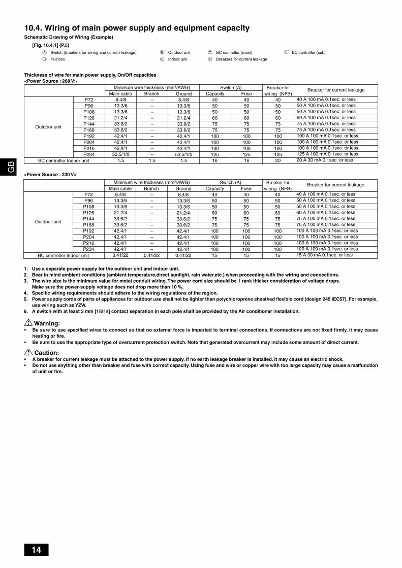
Warning:• Be sure to use specified wires to connect so that no external force is imparted to terminal connections. If connections are not fixed firmly, it may cause
heating or fire.• Be sure to use the appropriate type of overcurrent protection switch. Note that generated overcurrent may include some amount of direct current.
Caution:• A breaker for current leakage must be attached to the power supply. If no earth leakage breaker is installed, it may cause an electric shock.• Do not use anything other than breaker and fuse with correct capacity. Using fuse and wire or copper wire with too large capacity may cause a malfunction
of unit or fire.
1. Use a separate power supply for the outdoor unit and indoor unit.2. Bear in mind ambient conditions (ambient temperature,direct sunlight, rain water,etc.) when proceeding with the wiring and connections.3. The wire size is the minimum value for metal conduit wiring. The power cord size should be 1 rank thicker consideration of voltage drops.
Make sure the power-supply voltage does not drop more than 10 %.4. Specific wiring requirements should adhere to the wiring regulations of the region.5. Power supply cords of parts of appliances for outdoor use shall not be lighter than polychloroprene sheathed flexible cord (design 245 IEC57). For example,
use wiring such as YZW.6. A switch with at least 3 mm [1/8 in] contact separation in each pole shall be provided by the Air conditioner installation.
10.4. Wiring of main power supply and equipment capacitySchematic Drawing of Wiring (Example)
[Fig. 10.4.1] (P.5)
A Switch (breakers for wiring and current leakage) B Outdoor unit C BC controller (main) C' BC controller (sub)
D Pull box E Indoor unit F Breakers for current leakage
Thickness of wire for main power supply, On/Off capacities<Power Source : 208 V>
Outdoor unit
BC controller Indoor unit
40 A 100 mA 0.1sec. or less50 A 100 mA 0.1sec. or less50 A 100 mA 0.1sec. or less60 A 100 mA 0.1sec. or less75 A 100 mA 0.1sec. or less75 A 100 mA 0.1sec. or less100 A 100 mA 0.1sec. or less100 A 100 mA 0.1sec. or less100 A 100 mA 0.1sec. or less125 A 100 mA 0.1sec. or less20 A 30 mA 0.1sec. or less
Breaker for current leakage
40505060757510010010012520
40505060757510010010012516
40505060757510010010012516
8.4/813.3/613.3/621.2/433.6/233.6/242.4/142.4/142.4/1
53.5/1/01.5
8.4/813.3/613.3/621.2/433.6/233.6/242.4/142.4/142.4/1
53.5/1/01.5
Switch (A)Minimum wire thickness (mm2/AWG)Capacity Fuse
P72P96P108P126P144P168P192P204P216P234
––––––––––
1.5
Breaker forwiring (NFB)Main cable Branch Ground
<Power Source : 230 V>
Outdoor unit
BC controller Indoor unit
40 A 100 mA 0.1sec. or less50 A 100 mA 0.1sec. or less50 A 100 mA 0.1sec. or less60 A 100 mA 0.1sec. or less75 A 100 mA 0.1sec. or less75 A 100 mA 0.1sec. or less100 A 100 mA 0.1sec. or less100 A 100 mA 0.1sec. or less100 A 100 mA 0.1sec. or less100 A 100 mA 0.1sec. or less15 A 30 mA 0.1sec. or less
Breaker for current leakage
40505060757510010010010015
40505060757510010010010015
40505060757510010010010015
8.4/813.3/613.3/621.2/433.6/233.6/242.4/142.4/142.4/142.4/10.41/22
8.4/813.3/613.3/621.2/433.6/233.6/242.4/142.4/142.4/142.4/1
0.41/22
Switch (A)Minimum wire thickness (mm2/AWG)Capacity Fuse
P72P96P108P126P144P168P192P204P216P234
––––––––––
0.41/22
Breaker forwiring (NFB)Main cable Branch Ground

15
GB
DF
EI
NL
PG
RR
UT
RC
ZS
VS
LH
GP
O
11. Test run
11.1. The following phenomena do not represent trouble (emergency)
12. Information on rating plate
P7210.5 [23 LBS 3oz]
243 [536]
ModelRefrigerant (R410A) kgAllowable pressure (Ps)Net weight kg [LBS]
P9613.0 [28 LBS 11oz]
260 [574]
P10813.0 [28 LBS 11oz]
260 [574]
P12616.5 [36 LBS 7oz]
304 [672]
P14416.5 [36 LBS 7oz]
304 [672]
P16822.0 [48 LBS 9oz]
494 [1090]
P19222.0 [48 LBS 9oz]
494 [1090]
P20422.0 [48 LBS 9oz]
494 [1090]
P21622.0 [48 LBS 9oz]
494 [1090]
P23422.0 [48 LBS 9oz]
494 [1090]
MANUFACTURER: MITSUBISHI ELECTRIC CORPORATIONAIR-CONDITIONING & REFRIGERATION SYSTEMS WORKS 5-66, TEBIRA, 6-CHOME, WAKAYAMA CITY, JAPAN
HP: 4.15 MPa [601 psi], LP: 2.21 MPa [320 psi]
Display of remote controllerNormal display
“Cooling (heating)” flashes
Normal display
Normal display
Defrost displayNo lighting
Heat ready
Normal display
“HO” or “PLEASE WAIT” flashes
Light out
CauseThis is not a trouble as it is just a selecting sound.
When multiple indoor units (max. 3) are connected to the same branch of the BCcontroller, the heating (cooling) operation cannot be performed while anotherindoor unit is performing a cooling (heating) operation.Because of the control operation of auto vane, it may change over to horizontalblow automatically from the downward blow in cooling in case the downwardblow operation has been continued for 1 hour. At defrosting in heating, hot adjust-ing and thermostat OFF, it automatically changes over to horizontal blow.Ultra-low speed operation is commenced at thermostat OFF.Light air automatically changes over to set value by time or piping temperature atthermostat ON.The fan is to stop during defrosting.Fan is to run for 1 minute after stopping to exhaust residual heat (only in heating).
Ultra low-speed operation for 5 minutes after SW ON or until piping temperaturebecomes 35°C [95°F], low speed operation for 2 minutes thereafter, and then setnotch is commenced. (Hot adjust control)When the outdoor unit is being cooled and the refrigerant is resting, warming upoperation is performed for at least 30 minutes to warm the compressor (onlyP72).During this time, only the fan operates.System is being driven.Operate remote controller again after “HO” or “PLEASE WAIT” disappear.
After a stop of cooling operation, unit continues to operate drain pump for threeminutes and then stops it.Unit continues to operate drain pump if drainage is generated, even during astop.
PhenomenonIndoor unit and BC controller generate soundat the cooling/heating change over sometime.Indoor unit does not perform cooling (heat-ing) operation.
The auto vane runs freely.
Fan setting changes during heating.
Fan stops during heating operation.Fan does not stop while operation has beenstopped.No setting of fan while start SW has beenturned on.
Outdoor unit does not operate by turningswitch on.
Indoor unit remote controller shows “HO” or“PLEASE WAIT” indicator for about five min-utes when turning ON universal power supply.Drain pump does not stop while unit has beenstopped.Drain pump continues to operate while unithas been stopped.

WT04552X01
HEAD OFFICE: MITSUBISHI DENKI BLDG., 2-2-3, MARUNOUCHI, CHIYODA-KU, TOKYO 100-8310, JAPAN
Please be sure to put the contact address/telephone number onthis manual before handing it to the customer.
This product is designed and intended for use in the residential, commer-cial and light-industrial environment.
Printed in Japan