Illumi Shower Fan Complete - Free Instruction Manuals
12
1 Xpelair Simply Silent TM Illumi Shower Fan Complete Installation and Maintenance Instructions SSISFC100 (93087AW) IMPORTANT - PLEASE READ Do read the entire instruction leaflet before commencing installation. Do check that the electrical rating shown on the unit matches the mains supply. Rating label is located inside the back-plate. This appliance is intended for connection to fixed wiring only, WITH A MAXIMUM FUSE RATING 5A. Do install the product with a means for disconnection in all poles in the fixed wiring. Do ensure the mains supply is switched off before attempting to make electrical connections or carry out any maintenance or cleaning. All installations must be supervised by a qualified electrician. Installations and wiring must conform to current IEE Regulations (UK), local or appropriate regulations (other countries). Please leave this leaflet with the product for the benefit of the user UK customers: If you have any queries before or after installing this product call the Xpelair Helpline on +44 [0]344 879 3588. Our engineers are there to help you during normal office hours. Customers outside the UK: Please contact your local Xpelair distributor.
Transcript of Illumi Shower Fan Complete - Free Instruction Manuals

1
Xpelair Simply SilentTM
Illumi Shower Fan Complete
Installation and Maintenance Instructions
SSISFC100 (93087AW)
IMPORTANT - PLEASE READ
Do read the entire instruction leaflet before commencing installation.
Do check that the electrical rating shown on the unit matches the mains supply. Rating label is located inside the back-plate.
This appliance is intended for connection to fixed wiring only, WITH A MAXIMUM FUSE RATING 5A.
Do install the product with a means for disconnection in all poles in the fixed wiring.
Do ensure the mains supply is switched off before attempting to make electrical connections or carry out any maintenance or cleaning.
All installations must be supervised by a qualified electrician. Installations and wiring must conform to current IEE Regulations (UK), local or appropriate regulations (other countries).
Please leave this leaflet with the product for the benefit of the user
UK customers:
If you have any queries before or after installing this product call the Xpelair Helpline on +44 [0]344
879 3588. Our engineers are there to help you during normal office hours.
Customers outside the UK: Please contact your local Xpelair distributor.

2
The Xpelair Simply SilentTM Illumi Shower Fan Complete has the following features:
Single speed extraction
12 V (ac) fan operation
12 V (dc) light operation
When switched off, the fan continues to run for a pre-set delay from 30 seconds to 30 minutes
A transformer provides a Safety Extra Low Voltage (SELV) power supply.
THE APPLIANCE IS DOUBLE INSULATED AND DOES NOT REQUIRE AN EARTH CONNECTION.
The contents of this kit includes:
1x Xpelair Simply SilentTM Illumi Shower Fan Complete unit
1x Safety Extra Low Voltage (SELV) Transformer
1x 3m flexible duct
1x External Wall Grill
2x Tie wraps
7x Screws and wall plugs
This appliance can be used by children aged from 8 years and above and persons with reduced physical, sensory capabilities or lack of experience and knowledge, if they have been given supervision or instruction concerning the use of the appliance in a safe way and understand the hazards involved. Children shall not play with the appliance. Cleaning and maintenance of the appliance shall not be made by children.
Before any cleaning or maintenance, isolate the fan completely from the mains supply. A means of disconnection in all poles must be provided in the fixed wiring in accordance with the wiring rules. When the fan is installed in a room containing a fuel burning appliance, precautions must be taken to avoid the backflow of
gasses into the room from the open flue of the burning appliance.

3
C
FIGURE 2 - SELV Transformer Dimensions
Dimensions in mm
FIGURE 1 - Unit Dimensions
Dimensions in mm

4
FIGURE 3 – Opening the unit
FIGURE 4 - Fixing positions
Dimensions in mm

5
I2
FIGURE 5 - Ducting DOs and DON’Ts GOOD – Any condensation build-up will run towards external vent. BAD – Any condensation build-up will run back into the room. BAD – Any condensation will be trapped, causing collected water to stagnate, constrict or even block the air flow through the duct.
6
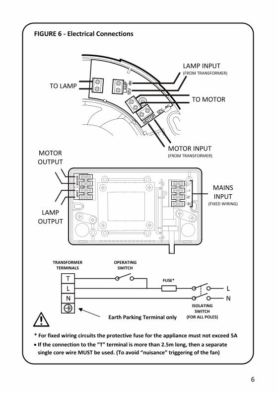
FIGURE 6 - Electrical Connections
* For fixed wiring circuits the protective fuse for the appliance must not exceed 5A
If the connection to the “T” terminal is more than 2.5m long, then a separate
single core wire MUST be used. (To avoid “nuisance” triggering of the fan)
LAMP INPUT (FROM TRANSFORMER)
TO LAMP
MOTOR INPUT (FROM TRANSFORMER)
TO MOTOR
TRANSFORMER TERMINALS
OPERATING SWITCH
FUSE*
ISOLATING SWITCH
(FOR ALL POLES)
MOTOR OUTPUT
MAINS INPUT
(FIXED WIRING)
LAMP OUTPUT
Earth Parking Terminal only

7
Where to locate the unit
Locate in the ceiling above the shower area or cubicle.
At least 110mm from the edges of the mounting surface to the centre of the hole.
Not where ambient temperatures are likely to exceed 50°C.
If installing in a room containing a fuel burning device which has a non-balanced flue, it is the installer's responsibility to ensure that there is enough replacement air to prevent fumes being drawn down the flue when the fan is operating up to maximum extract. Refer to Building Regulations for specific requirements.
Exhaust air must not be discharged into a flue used for exhausting of fumes from appliances supplied with energy other than electric. Requirements of all authorities concerned must be observed for exhaust air discharge and intake flow rates.
Not suitable for use in possible chemical corrosive atmospheres.
What the installer will need
3mm electrician’s screwdriver and No.1 or 2 Pozi-drive screwdriver.
Before you start, you will also need
A 100mm diameter prepared hole for the unit.
A 100mm diameter prepared hole for the external vent. Ideally positioned to allow condensation to run away from the first bend in the duct toward the external vent. Refer to Figure 5.
A planned route for the duct, please consider the following: - The duct is 3m in length. - The fan will perform best if ducting is kept as straight and as short as possible. Avoid sharp
corners. - From the back of unit the duct should protrude straight out for at least 60mm before the first
bend. This is to ensure that the backdraft flaps are free to open and close. - Laying the duct so that after the first bend the condensation runs out towards the external
vent. Refer to Figure 5.
Some suitable insulation for the duct, if the duct passes through a cold or unheated space. Alternatively you can use an insulated duct, available to purchase from Xpelair (Ref: 89847AA).
A means for disconnection of all poles (Isolating switch). This must be incorporated into the fixed wiring in accordance with the wiring regulations. If metal switch boxes are used, earthing regulations must be followed.
A suitable operating switch.
Two lengths of suitably rated 2 core cable for wiring from transformer to the unit. See Table 1 below.
Suitably rated 3 core cable for wiring from the mains supply to the transformer, via the isolating switch and operating switch, as necessary.
Table 1 - Guidelines for the maximum cable length between the transformer and unit:
Limited to 0.3 volts drop, corresponding to 1.5% reduction in fan performance.
Flexible Fixed
Conductor size (mm²) 0.75 1.00 1.50 2.50
Recommended max cable run (m) 4.50 6.00 9.00 15.00
Limited to 0.5 volts drop, corresponding to 3% reduction in fan performance.
Flexible Fixed
Conductor size (mm²) 0.75 1.00 1.50 2.50
Recommended max cable run (m) 7.50 10.00 15.00 25.00

8
INSTALLATION
Note: Installation assumes the unit and grille components can be installed before the ducting. If the ducting will be inaccessible after either of these are in place, the opening for that component should be increased to 110mm, this will allow the ducting to pass through the hole for attachment. The ducting can then be installed first.
Installing the isolating switch and cables
1. Check there are no buried pipes or cables (e.g. electricity, gas, water) in the wall or above the ceiling where the isolating switch and operating switch is to be located. If in doubt, seek professional advice.
WET ROOMS: THE OPERATING SWITCH MUST BE SITUATED SO THAT IT CANNOT BE TOUCHED BY PERSONS MAKING USE OF THE BATH OR SHOWER.
2. Isolate the mains supply.
WARNING: DO NOT MAKE ANY CONNECTIONS TO THE ELECTRICAL SUPPLY AT THIS STAGE.
3. Lay the cable from the isolating switch to the transformer location via an operating switch. 4. Lay the two lengths of suitably rated 2 core cable from the transformer to the unit location. 5. Lay the cable from the isolating switch to the point of connection to the mains supply. 6. Install the isolating switch and operating switch as per the manufacturer’s instructions. 7. Make all connections within the isolating switch and the operating switch only.
Installing the Simply SilentTM Illumi Shower Complete unit
1. Remove the front cover by depressing the latch through the slot on the side of the cover and pulling away. Refer to Figure 3.
IF WORKING ABOVE GROUND FLOOR LEVEL, SAFETY PRECAUTIONS MUST BE OBSERVED.
Mounting using the fixing screws and plugs: 2. Insert the back-plate into the 100mm hole in the desired orientation. Orientate so that the cover
latch release slot is easily accessible. 3. Mark the centres of the screw holes and cable entry. Refer to Figure 4. 4. Remove back-plate and drill holes to the appropriate sizes. 5. Fit wall plugs (supplied), as required. 6. Reposition back-plate and secure with screws (supplied). Take care not to overtighten.
Mounting using the clamping brackets:
7. Insert the back-plate into the 100mm hole in the desired orientation. 8. Tighten the two clamping brackets. Tighten both brackets a little at a time until secured.
9. To wire unit - Refer to Wiring the Simply SilentTM Illumi Shower Fan Complete unit. 10. To re-fit the front cover, first hook in the side opposite to the latch and swing closed until latch clips
into place. Ensure any wiring is not pinched when closing the unit. Do not press on the light unit or outer fascia cover; only apply pressure over the latch.
Installing the External Vent Grille
1. Insert the Vent Grille into the 100mm hole in the desired orientation. 2. Mark the centres of the screw holes. 3. Remove Vent Grille and drill holes to the appropriate sizes. 4. Fit wall plugs (supplied), as required. 5. Reposition Vent Grille and secure with screws (supplied).

9
Installing the Flexible Duct
1. Lay the duct from the back of the unit to the external vent grille. Please ensure: - Any bends are not kinked. - From the back of unit the duct should protrude out straight for at least 60mm before the first
bend. This is to ensure that the backdraft flaps are free to open and close. - After the first bend the duct runs downwards so that any condensation that occurs runs out
towards the external vent. Refer to Figure 5. - Duct is fairly taut but not overly stretched that there is risk of pulling itself away from either
end. 2. Push ducting over the back of the unit and secure with tie-wraps. 3. Push ducting over the back of the external grille and secure with tie-wraps.
Installing the Transformer
The transformer can be fixed directly to the wall or on a horizontal surface. IF FIXING TO A WALL, THE TRANSFORMER MUST BE ORIENTATED AS SHOWN IN FIGURE 2 TO FULFIL INGRESS PROTECTION REQUIREMENTS.
1. Remove the screws securing the cover, remove the cover. 2. Position transformer as desired. When wall mounting, the transformer must be orientated as
shown in Figure 2 to fulfil ingress protection requirements. 3. Mark the centres of the screw holes. Refer to Figure 4. 4. Remove and drill holes to the appropriate sizes. 5. Fit wall plugs (supplied), as required. 6. Open the knockouts for cable entry. 7. Reposition transformer and secure with screws (supplied). 8. Refer to Wiring the Transformer section. 9. Re-fit the cover with securing screws.
IMPORTANT: THE TRANSFORMER MUST NOT BE COVERED BY LOFT INSULATION
Wiring the Transformer
FULLY ISOLATE ELECTRICAL SUPPLY TO THE UNIT
1. Route the low voltage and mains supply cables through the appropriate knockouts. IMPORTANT: Take note of the limitations on the T terminal cable given in Figure 6.
2. Locate the cables in the cable clamps and make connections as shown in Figure 6. Ensure all connections are tight.
Wiring the Simply SilentTM Illumi Shower Fan Complete unit
FULLY ISOLATE ELECTRICAL SUPPLY TO THE UNIT
1. Route the cables leading from the transformer to the opening in the back-plate and connect as shown in Figure 6.
2. Route the cable from the light unit through and up the leg of the front cover and connect as shown in Figure 6.
Wiring mains connection
ONLY AFTER ALL COMPONENTS HAVE BEEN INSTALLED CORRECTLY, ELECTRICAL CONNECTIONS MADE AND CHECKED AND ALL COVERS ARE IN PLACE SHOULD YOU CONTINUE.
1. Connect the wiring from the isolating switch to the electrical supply. Refer to Figure 6. The
maximum rating for the fixed wiring circuit is 5A. 2. Switch on mains supply.

10
Using Simply SilentTM Illumi Shower Fan Complete
Operate the unit using an on/off switch (not supplied). When the switch has been operated, the light switches on immediately, however, the fan may take up to 10 seconds to turn on. When the switch is turned off, the light will switch off immediately, but the fan continues to operate for the set time delay.
Adjusting the fan overrun time
Control for the over-run timer is located on the transformer
To adjust the time turn the control clockwise to increase and anti-clockwise to decrease. Time can be set between 30 seconds and 30 minutes.
Bulb replacement (Tools required: 3mm electrician’s screwdriver and No.1 or 2 Pozi-drive screwdriver)
FULLY ISOLATE ELECTRICAL SUPPLY TO THE UNIT
1. Carefully remove the front cover by the latch through the slot on the side of the cover and pulling away. Refer to Figure 3.
2. Disconnect the wiring to the light unit from the terminal block. 3. Remove the screw on the top of the cone cover and remove cover. 4. Carefully pull the lamp housing from the front cover. 5. Remove the lamp by carefully opening the retaining hooks and pulling the lamp free. 6. Replace with new lamp. Avoid touching the individual LEDs or other components on the circuit
board. 7. Re-fit lamp housing to the front cover. Ensure gasket seal is correctly in place. 8. Ensure cable is routed correctly before re-fitting the cone cover and secure using the screw. 9. Re-connect the wires to the terminal block. Refer to Figure 6 if necessary. 10. To re-fit the front cover, first hook in the side opposite to the latch and swing closed until latch clips
into place. Ensure any wiring is not pinched when closing the unit. Do not press on the light unit or outer fascia cover; only apply pressure over the latch.
Cleaning
DO NOT USE STRONG DETERGENTS, SOLVENTS OR CHEMICAL CLEANERS.
DO NOT IMMERSE THE UNIT IN, OR SPRAY DIRECTLY WITH, WATER OR ANY OTHER LIQUIDS.
BEFORE CLEANING, FULLY ISOLATE ELECTRICAL SUPPLY TO THE UNIT
The unit should be periodically wiped clean in position with a damp cloth and mild detergent.
No other maintenance is required.

11
This page has been left blank for the addition of any notes you may wish to make.

12
UK Only: Xpelair products deliver reliable service for normal, household use in domestic settings. All Xpelair products are individually tested before leaving the factory.
If you are a consumer and you experience a problem with your Xpelair product, which is found to be defective due to faulty materials or workmanship within the Warranty Period, this Xpelair warranty will cover repair, or at the discretion of Xpelair, replacement with a functionally equivalent Xpelair product.
The Xpelair Warranty Period is two calendar years from the date of purchase of your Xpelair product, or the date of delivery of the product, if later. The Xpelair Warranty is conditional upon you providing the original purchase receipt as proof of purchase. Please therefore retain your receipt as proof of purchase.
If you do experience a problem with your Xpelair product please call the Helpline on +44 [0]344 879 3588 or at the address below. We will need
details of your Xpelair product, and a description of the fault which has occurred. Once we receive your information and proof of purchase we will contact you to make the necessary arrangements. Customers Outside UK – See international below. If your Xpelair product is not covered by this Xpelair Warranty there may be a charge to repair your product. However, we will contact you for an agreement to any charges before any chargeable service is carried out. What is not covered by an Xpelair Warranty? The Xpelair Warranty does not cover the following: • Any fault or damage to your Xpelair product due to faulty materials or workmanship occurring outside the two-year Warranty Period. • Any fault or damage occurring to any pre-owned product or to any other equipment or property. • Accidental damage to your Xpelair product or damage to your Xpelair product from external sources (for example, transit, weather, electrical outages or power surges). • Fault or damage to your Xpelair product which is: • Not due to faulty materials or workmanship or which is due to circumstances outside Xpelair’s control. • Caused by use of your Xpelair product for anything other than normal domestic household purposes in the country where it was purchased. • Caused by any misuse, abuse or neglect of the Xpelair product, including but not limited to any failure to use it in accordance with the Operating Instructions supplied with the product. • Caused by any failure to assemble, install, clean and maintain your Xpelair product in accordance with the Operating Instructions supplied with the product unless this was carried out by Xpelair or its authorised dealers. • Caused by repairs or alterations to your Xpelair product not carried out by Xpelair service personnel or its authorised dealer(s). • Caused by use of any consumables or spare parts for your Xpelair product which are not Xpelair specified. Terms and Conditions
• The Xpelair Warranty is valid for Xpelair from the date of purchase of your Xpelair product from a recognised retailer in the country of purchase and use, or the date of delivery of the product if later, always provided the original receipt has been retained and is produced as proof of purchase. • You must provide to Xpelair or its authorised agents on request the original receipt as proof of purchase and - if required by Xpelair - proof of delivery. If you are unable to provide this documentation, you will be required to pay for any repair work required. • Any repair work under the Xpelair Warranty will be carried out by Xpelair or its authorised dealer(s) and any parts that are replaced will become the property of Xpelair. Any repairs performed under the Xpelair Warranty will not extend the Warranty Period. • Any replacement of your Xpelair product by Xpelair during the Warranty Period will start the two-year Warranty Period afresh from the date of delivery of the replacement Xpelair product to you. • The Xpelair Warranty does not entitle you to recovery of any indirect or consequential loss or damage including but not limited to loss or damage to any other property. • The Xpelair Warranty is in addition to your statutory rights as a consumer and your statutory rights are not affected by this Xpelair Warranty. Contact Xpelair If you have any questions about what the Xpelair Warranty covers and does not cover or how to claim under the Xpelair Warranty, please contact us using the information below. Contact details Millbrook House, Grange Drive, Hedge End, Southampton, SO30 2DF
Telephone: +44 (0)344 879 3588
Email: [email protected]
http://www.xpelair.co.uk
International
Warranty: Contact your local distributor or Xpelair direct for details. Technical advice and service: Contact your local Xpelair distributor. Xpelair: A brand of GDC Group Limited, trading as Glen Dimplex Heating & Ventilation. Glen Dimplex. All rights reserved. Material contained in the publication may not be reproduced in whole or in part, without prior permission in writing of Glen Dimplex.
For electrical products sold within the European Community. At the end of the electrical products useful life it should not be disposed of with household waste. Please recycle where facilities exist. Check with a Local Authority or retailer for recycling advice in your country. Batteries should be disposed of or recycled in accordance with WEEE Directive 2012/19/EU. Packaging should be recycled where possible.
Part No: 25909AA (Revision F)
Part No: 25909AA (Revision F)