ILFORD 50/60 Hz OPERATING MANUAL ILFOLAB 1250 RC
26
IL882 VARIABLE SPEED PRINT DRYER FOR HIGH QUALITY BLACK AND WHITE PRINT DRYING 50/60 Hz OPERATING MANUAL ILFORD ILFOLAB 1250 RC 1st Proof rev A - March 1997
Transcript of ILFORD 50/60 Hz OPERATING MANUAL ILFOLAB 1250 RC

IL882
VARIABLE SPEED PRINT DRYERFOR HIGH QUALITYBLACK AND WHITE PRINT DRYING
50/60 Hz OPERATING MANUALILFORD
ILFOLAB1250RC
1st Proof rev A - March 1997

1
2
3
4
5
6
7
8
9
10
11
12
13
14
15
SAFETY PRECAUTIONSYour photographic equipment is powered by mains electricity,and is designed to comply with international electrical safetystandards. However, basic safety precautions must always befollowed when operating electrical equipment, including thefollowing, where applicable:
Read and understand all instructions and equipment labels.
Close supervision is necessary when the equipment is being usedby inexperienced personnel.
Take care to avoid burns. Some internal parts of the equipmentcan become very hot with continuous use.
Do not operate equipment that has been dropped or damaged,or has damaged electrical leads. Have the equipment examinedby qualified personnel.
Do not allow any electrical lead to touch hot surfaces.
Ensure the leads are arranged such that they cannot be pulled ortripped over.
Ensure extension leads are of a suitable current rating to preventthe lead overheating.
Always unplug or isolate the equipment when it is not in use.Never pull plugs out by holding the lead.
For equipment connected to the electrical mains supply by a plugand socket arrangement, ensure the socket is installed near to theequipment and is easily accessible at all times.
Do not touch electrical components with wet or damp hands.
Ensure the air flow through the vents is not obstructed whenequipment is switched on.
Do not dismantle the equipment unless you are qualified to doso. Incorrect assembly can cause hazards both to yourself and tothe equipment.
All equipment, no matter how well made, can break down and,therefore, must not be left unattended for long periods of timewhile it is switched on.
Always unplug or isolate the equipment before connecting ordisconnecting any plugs supplying electrical power to or from theequipment.
Always obey local codes of practice, particularly for installationrequirements.
Do not destroy these instructions

CONTENTS
1
22.12.22.32.4
33.13.23.33.4
4
5
66.16.26.36.46.5
7
8
1
PICTOGRAMS 2
INTRODUCTION 5
CONTROLS AND INDICATORS 7‘POWER’ light 7‘READY’ light 7Dryer control 7Speed control 7
INSTALLATION 9Print receive tray 9Location 9Electricity supply 9Removing yellow transit wedges 9
DRYING PRINTS 10
SWITCHING OFF 11
CLEANING AND SIMPLE REPAIRS 13Daily routine 13Cleaning the front roller assembly 13Replacing a mains fuse 14Replacing a roller tension spring 14Removing rear rollers/adjusting print exit guide 15
FAULT FINDING 18
SPECIFICATION 21
INSERTS94031.2A.GB Wall chart - Operating

PICTOGRAMS
2
The following pictograms are used on labels fixed to the dryer.Please ensure you understand their meaning.
Electrical hazard - refer to manual
Caution moving rollers
IL895

3

Figure 1.1 ILFOLAB 1250RC dryer - typical installation
ILFOLAB1250RC
ILFORD
IL883
4
1INTRODUCTION
5
See figure 1.1.
The ILFOLAB 1250RC variable speed dryer is designed to dryILFORD black and white resin coated papers to a very highstandard. The dryer will dry up to 380 20.3x25.4cm (8x10 inches) prints per hour, and has a maximum feed width of50.8cm (20 inches).
For uniform drying and greater efficiency, prints are dried byinfra-red, fan assisted heaters. The print transport speed isvariable for precise control of a wide range of drying conditionsand materials.
This manual gives full instructions for installing and operating theILFOLAB 1250RC dryer. For ease of description, it is assumedthe left and right hand sides of the dryer are determined whenfacing the dryer at the paper feed (front) end.

Figure 2.1 Controls and indicators
IL884A
ILFOLAB1250RC
ILFORD
1 2
6
2CONTROLS ANDINDICATORS
2.1
2.2
2.3
2.4
7
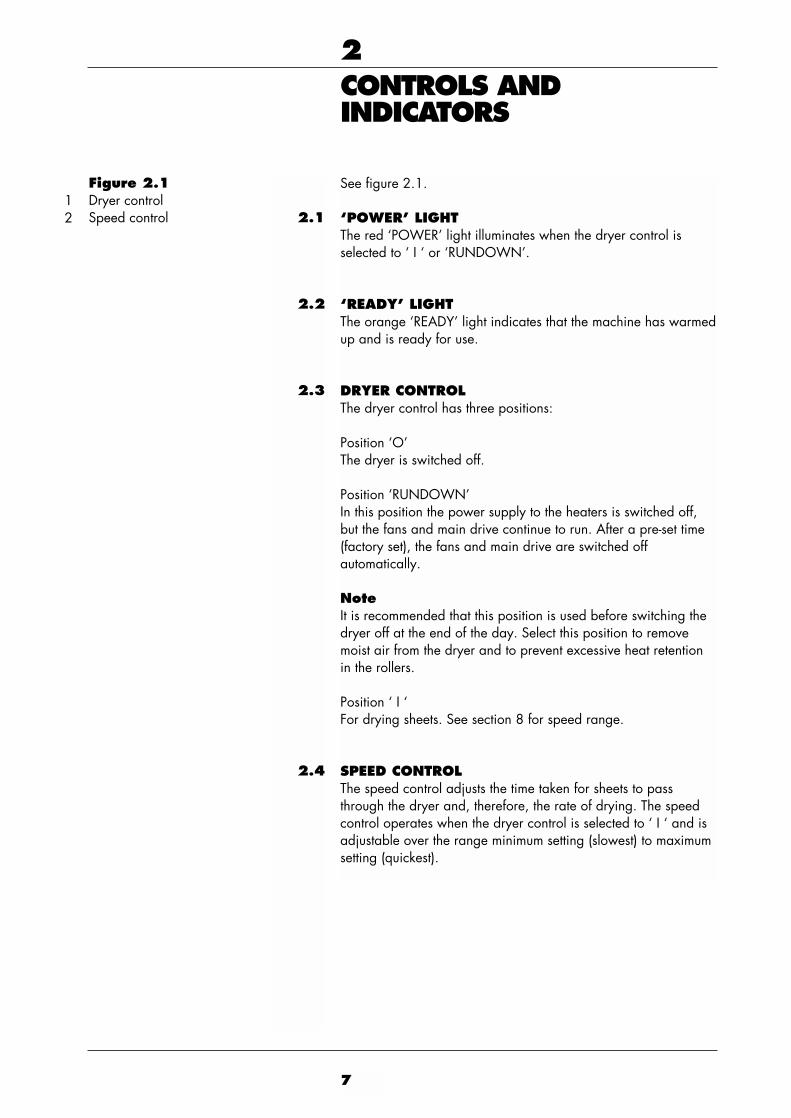
See figure 2.1.
‘POWER’ LIGHT The red ‘POWER’ light illuminates when the dryer control isselected to ‘ I ‘ or ‘RUNDOWN’.
‘READY’ LIGHT The orange ‘READY’ light indicates that the machine has warmedup and is ready for use.
DRYER CONTROL The dryer control has three positions:
Position ‘O’ The dryer is switched off.
Position ‘RUNDOWN’ In this position the power supply to the heaters is switched off,but the fans and main drive continue to run. After a pre-set time(factory set), the fans and main drive are switched offautomatically.
NoteIt is recommended that this position is used before switching thedryer off at the end of the day. Select this position to removemoist air from the dryer and to prevent excessive heat retentionin the rollers.
Position ‘ I ‘ For drying sheets. See section 8 for speed range.
SPEED CONTROLThe speed control adjusts the time taken for sheets to passthrough the dryer and, therefore, the rate of drying. The speedcontrol operates when the dryer control is selected to ‘ I ‘ and isadjustable over the range minimum setting (slowest) to maximumsetting (quickest).
Figure 2.1Dryer controlSpeed control
12

Figure 3.1 Installation
IL885A
A
B
300mm(12in)
300mm(12in)
350mm(13.8in)
3
2
2
1
6
10
4
8
9
5
7
8

3INSTALLATION
3.1
3.2
3.3
3.4
1
2
3
4
9
See figure 3.1.
PRINT RECEIVE TRAYSecure the tray with the screws supplied, as shown in detail B.
LOCATIONPosition the dryer on a firm bench or table at a convenientworking height. The dimensions shown in detail A are minimumrequirements to allow for adequate air circulation and for theprint receive tray. Position the wet-print dish under the dryer.
ELECTRICITY SUPPLYConnect the lead supplied to the dryer mains input plug and to astandard wall socket. The lead fits one way only.
REMOVING YELLOW TRANSIT WEDGESSee figures 3.1 and 3.2.
CAUTIONTo enable the dryer to operate correctly, it is important to removethe two yellow transit wedges prior to use.
Press the release button on the left hand side of the dryer andopen the dryer until the lid is held by the restraining arm.
Lift the four-roller assembly away.
Remove the two transit wedges from between the roller bearings.
Re-assemble the dryer and close the lid.
IL886
Figure 3.2 Location of transit wedges
Figure 3.1Release buttonYellow transit wedgesFour-roller assemblyRestraining armFeed trayMains fuseElectricity supply leadPrint receive trayPan head screwWet-print dish
123456789
10

4DRYING PRINTS
IL887A
IL888A
IL889
ILFOLAB1250RC
ILFORD
10
Fill the wet-print dish withenough cold water to coverthe washed prints. Switch theelectrical supply on. Turn thedryer control to ‘ I ‘. The red‘POWER’ light illuminates.
1
2
3
Allow about 11/2 minutes forthe orange ‘READY’ light toswitch on. During this time,transfer the washed prints tothe wet-print dish. As aguide, set the speed controlto position 6 to dry resincoated paper sheets.
Feed prints emulsion side up.Ensure prints are fedsquarely. Feed small printswith the short edge leading.Do not overlap one print withanother - allow 2 secondsbetween the trailing edge ofone print and the leadingedge of the next.

5SWITCHING OFF
IL890A
IL891A
11
Turn the dryer control to‘RUNDOWN’. If the dryer isto be used again later thesame day, the control can beleft in this position.
To switch the dryer offcompletely, carry outoperation 1 and wait for thefans and main drive to stop.Then turn the dryer control to‘O’. Switch the electricalsupply off.
1
2

Figure 6.1 Adjusting print exit guide
IL892A
A B
10
3
8
9
76
5
4
7
68
1
2
12

6CLEANING AND SIMPLEREPAIRS
6.1
1
2
6.2
1
2
3
4
5
13
See figure 6.1.
Cleaning is the only regular maintenance required on theILFOLAB 1250RC dryer. Regular cleaning will ensure correctoperation and consistently high drying quality.
CAUTIONDuring the following procedures, do not allow water to enterareas of the dryer containing electrical components. Please referto the Safety Precautions at the front of this manual.
DAILY ROUTINE
Change the water in the wet-print dish daily or more frequently ifnecessary.
Wipe the outside of the dryer with a damp cloth.
CLEANING THE FRONT ROLLER ASSEMBLYSee figure 3.1.
CAUTIONWhen cleaning the roller assembly, always take extreme carenot to damage the roller surfaces. Damaged roller surfaces willcause marks on subsequent prints.
If the four-roller assembly at the front of the dryer becomescontaminated, remove and clean it as follows:
Switch the electrical supply off.
Press the release button and open the dryer until the lid is heldsecurely by the restraining arm.
Lift the four-roller assembly away.
Thoroughly clean the rack with a soft lint free cloth and warmwater. More stubborn deposits on metal and plastic surfaces canbe removed using a soft bristle brush and warm water.
CAUTIONTo prevent a reduction in the quality of drying, particularly onglossy surfaces, do not use soap solutions or other cleaningagents on the rollers.
Refit the four-roller assembly and close the dryer.
Figure 6.1Upper roller, rearLower roller, rearLower coverRestraining armFront roller assemblyPrint exit guideVentilation grilleAlignment markWasherNut
123456789
10

6.3
1
2
3
4
6.4
1
2
3
14
REPLACING A MAINS FUSESee figure 6.2.
The mains fuse is located to the right of the dryer mains inputplug.
Switch the electrical supply off.
Remove the fuse by turning the fuseholder anti-clockwise with ascrewdriver.
Replace the fuse with one of the correct value (see section 8).
Refit the fuse by turning the fuseholder clockwise with ascrewdriver.
REPLACING A ROLLER TENSION SPRINGSee figure 6.3.
Roller tension springs are fitted on the four-roller assembly only.Springs are fitted to both ends of the roller pairs, as shown.
Switch the electrical supply off.
Press the release button and open the dryer until the lid is heldsecurely by the restraining arm.
Lift the four-roller assembly away.
IL893
Figure 6.2 Replacing a mains fuse

4
5
6
7
8
9
6.5
15
To remove a tension spring left hand side, release the socket setscrews and remove the gears and locating plate, as shown onDetail A.
Unhook and remove the spring from the end of the roller pair.
Fit a new spring around the roller bearings, as shown.
Refit the locating plate and gear. Secure each gear by tighteningthe socket set screw against the flat on the roller shaft.
To remove a tension spring right hand side as shown on Detail B, carry out operations 5 and 6.
Refit the roller assembly and close the dryer.
REMOVING REAR ROLLERS/ADJUSTING PRINT EXIT GUIDESee figure 6.1.
The gap between the print exit guide and the rear upper roller iscritical to ensure correct paper transport through the dryer.Initially, this gap is factory set. Under normal operatingconditions, the print exit guide must not be moved.
If, for any reason, the rear lower roller needs to be removed, theprint exit guide must first be moved to clear the way for theroller. This means that, when the rollers are replaced, the gapmust be reset as accurately as possible. To help with thisoperation, the print exit guide has an alignment mark at eachend as shown in detail A.
IL894
A
B
1
2 3 3
Figure 6.3 Replacing a roller tension spring
Figure 6.3GearLocating plateSpring
123

1
2
3
4
5
6
1
2
3
4
5
6
16
To remove the rear rollers, proceed as follows:
CAUTIONThis operation requires access to the electrical compartment.Please refer to the Safety Precautions at the front of this manual.
Switch the electrical supply off.
Press the release button and open the dryer until the lid is heldsecurely by the restraining arm.
Release the four screws and remove the lower cover.
Carefully remove the upper roller, complete with bearings.
Carry out the following operations only if the lower roller is to beremoved.
Slacken the four nuts securing the print exit guide to theventilation grille as shown in detail B and push the exit guidetowards the rear of the dryer.
Carefully lift the lower roller, complete with bearings and rollerdrive gear, away.
To replace the rear rollers, proceed as follows:
NoteCarry out operations 1, 2, 3, 7 and 8 only if the lower roller isbeing replaced.
Ensure the print exit guide is pushed towards the rear of thedryer and is not obstructing the lower roller.
Replace the lower roller, complete with bearings. Ensure theroller drive gear meshes with the idler gear.
Replace the upper roller, complete with bearings.
Carefully move the print exit guide towards the front of the dryeruntil the rear edge of the mark at each end of the guide isaligned with the front edge of the ventilation grille. Tighten thenuts securing the guide to the ventilation grille. Check thealignment is correct as shown in detail A.
Refit the lower cover. Secure the cover with the four screws andwashers.
Close the dryer.

7
8
17
Switch the electrical supply on.
When the dryer is ready, feed a number of wet sheets through,ensuring they exit the dryer without obstruction. If the sheets donot exit correctly, switch the electrical supply off and check thealignment of the print exit guide. Re-adjust the guide if necessary.

7FAULT FINDING
18
Sheet fed upside down Feed sheets emulsion side up
Prints pulled from the exit Leave prints to emerge fullyrollers from the dryer before handling
them
Dirty paper guides Remove roller assemblies and inspect guides. See figure 3.1. Clean guides as necessary
Dirty feed tray Clean feed tray. See figure 3.1
Paper guides bent Contact your local ILFORD Selling Company
Dryer speed too high Adjust speed control to a slowersetting
Faulty heater element Contact your local ILFORD Selling Company
Rollers operating incorrectly Replace any damaged or missing roller tension springs. See section 6.4. Clean rollers. See section 6.2. Ensure the yellow transit wedges have been removed. See section 3.4
Symptom Possible cause Remedy
Scratches on prints
Wet or damp prints
1
2
This section provides a list of checks to make should there be anyproblems with the dryer. If the problem persists, contact yournearest ILFORD Selling Company at the address shown on theback cover of this manual.
CAUTIONIf in doubt about making any of the checks consult a competentengineer. Any further repair work carried out by unqualifiedpersonnel could cause a hazard both to yourself and to theequipment, and may invalidate any guarantees applicable to theequipment.
NoteAn interlock switches off the fan motor, drive motor and heaters ifthe dryer lid is raised.

19
Dryer speed too high Adjust speed control to aslower setting
Prints not fully wetted before Ensure prints are completelydrying immersed in the wet-print dish
before drying
Dryer speed too low Adjust speed control to a faster setting
Dryer fan impeded Remove any obstruction from dryer air grille. Observe installation procedure. See section 3.2
Dryer speed too low Adjust speed control to a faster setting
Dryer speed too low Adjust speed control to a fastersetting
Dirty front roller assembly Clean front roller assembly.See section 6.2
Dryer not switched on or Connect dryer to electricalplugged in supply. Turn dryer control to
‘ I ‘
Dryer control set to Turn dryer control to ‘ I ‘‘RUNDOWN’
Dryer lid not closed correctly Ensure lid is closed and locked
Dryer mains fuse blown Replace mains fuse.See section 6.3
Faulty heater element Contact your local ILFORD Selling Company
Symptom Possible cause Remedy
Imperfect gloss onglossy prints
Excessive curl onprints
Surface blistering onprint
Glossy patches onmatt or pearl surfaces
Dull patches onsurfaces of driedprints
Dryer heaters and/orfan fail to operate
3
4
5
6
7
8
20
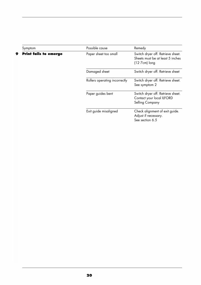
Paper sheet too small Switch dryer off. Retrieve sheet. Sheets must be at least 5 inches (12.7cm) long
Damaged sheet Switch dryer off. Retrieve sheet
Rollers operating incorrectly Switch dryer off. Retrieve sheet. See symptom 2
Paper guides bent Switch dryer off. Retrieve sheet. Contact your local ILFORD Selling Company
Exit guide misaligned Check alignment of exit guide. Adjust if necessary.See section 6.5
Symptom Possible cause Remedy
Print fails to emerge9

8SPECIFICATION
21
PERFORMANCE DATAControl switch selected to ‘ I ’Minimum speed setting : 17.5cm/min (7 inches/min)Maximum speed setting : 126cm/min (49.6 inches/min)
380 20.3x25.4cm (8x10 inches) prints per hour at speed setting12 and the control switch selected to ‘ I ‘
70 seconds
Typically 25 seconds for a 20.3x25.4cm (8x10 inches) printwith the speed setting at position 6 and the control switchselected to ‘ I ‘
PRINT SIZES ACCEPTED50.8cm (20 inches)
12.7cm (5 inches)
DRYER DIMENSIONS273mm (10.9 inches)
755mm (29.7 inches)
615mm (24.2 inches) including print receive tray
WEIGHT20kg (44lbs)
ELECTRICAL120V 230V60Hz 50HzSingle Single9A 4.25A1100W 1000W12A 6AFast blow Fast blow2x450W 2x450W
Dryer speedrange
Maximum output
Warm up time
Access time
Maximum width
Minimum length
Height
Width
Length
Dryer
VoltageFrequencyPhaseMaximum currentPower consumptionFuse valueFuse typeHeaters

22
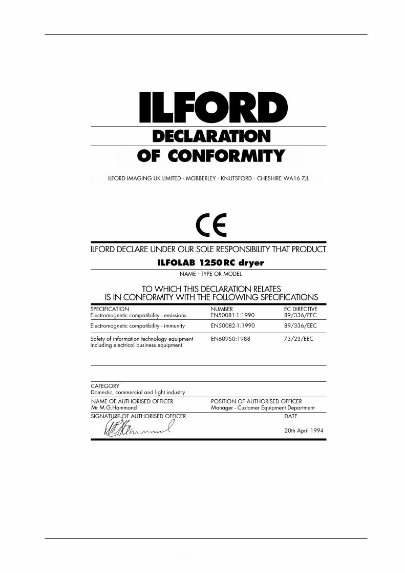
DECLARATIONOF CONFORMITY
ILFORD
ILFORD DECLARE UNDER OUR SOLE RESPONSIBILITY THAT PRODUCT
ILFOLAB 1250RC dryerNAME . TYPE OR MODEL
TO WHICH THIS DECLARATION RELATESIS IN CONFORMITY WITH THE FOLLOWING SPECIFICATIONS
SPECIFICATION NUMBER EC DIRECTIVEElectromagnetic compatibility - emissions EN50081-1:1990 89/336/EEC
Electromagnetic compatibility - immunity EN50082-1:1990 89/336/EEC
Safety of information technology equipment EN60950:1988 73/23/EECincluding electrical business equipment
CATEGORYDomestic, commercial and light industry
NAME OF AUTHORISED OFFICER POSITION OF AUTHORISED OFFICERMr M.G.Hammond Manager - Customer Equipment Department
DATE
20th April 1994
SIGNATURE OF AUTHORISED OFFICER
ILFORD IMAGING UK LIMITED . MOBBERLEY . KNUTSFORD . CHESHIRE WA16 7JL

Australia ILFORD Imaging Asia Pty LimitedMonash Corporate CentreUnit 1/10 Duerdin StreetClayton North3168 Victoria
BeneluxILFORD Imaging BeneluxFotografielaan, 182610 WilrijkBelgium
Canada ILFORD Imaging Canada Limited 361 Steelcase Road WestUnit No.4Markham Ontario L3R 3V8
FranceILFORD Imaging France SA10 Allee des Ginkgos69673 Bron - Cedex
Germany/AustriaILFORD Imaging GmbH Heinrich-Hertz-Str 1POB 10 11 68D-63265 Dreieich
Italy ILFORD Imaging Italia SpACorso Italia 1321047 Saronno (VA)
Switzerland ILFORD Imaging Switzerland GmbH Route de l’Ancienne Papeterie Case Postale 160CH-1723 Marly 1
United Kingdom ILFORD Imaging UK LimitedTown LaneMobberleyCheshire WA16 7JL
USA ILFORD Imaging USA Inc West 70 Century Road Paramus New Jersey 07653
If your country is not shown here, pleasecontact: Export Eastern Hemisphere ILFORD Imaging UK LimitedMobberleyCheshire WA16 7JLEngland
Webwww.ILFORD.com
Constant improvements in ILFORDproducts mean that changes in designor specification may occur from time totime. Any improvements will, however,maintain conformance of the productwith all relevant legislation. The right toalter the design and specification of theequipment without prior notice isaccordingly reserved.
Product names printed in capitals areILFORD trade marks.ILFORD Imaging UK LimitedMobberley Cheshire23 June 1998
Printed in England 94031A.GBApril 2002