IK-CU44A - Toshiba
28
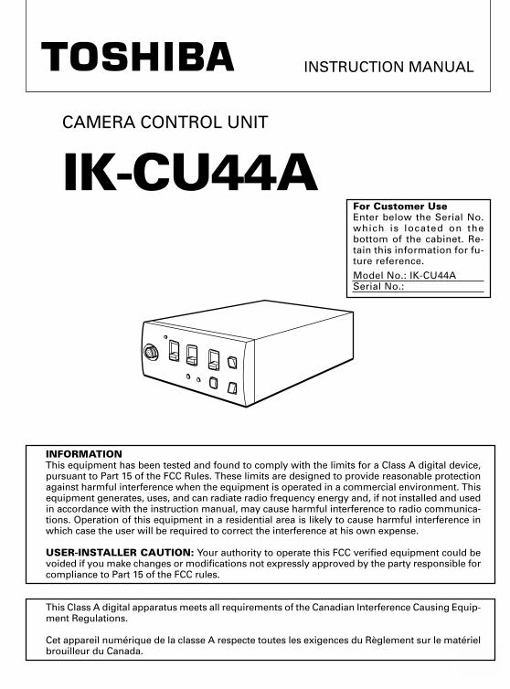
INFORMATION This equipment has been tested and found to comply with the limits for a Class A digital device, pursuant to Part 15 of the FCC Rules. These limits are designed to provide reasonable protection against harmful interference when the equipment is operated in a commercial environment. This equipment generates, uses, and can radiate radio frequency energy and, if not installed and used in accordance with the instruction manual, may cause harmful interference to radio communica- tions. Operation of this equipment in a residential area is likely to cause harmful interference in which case the user will be required to correct the interference at his own expense. USER-INSTALLER CAUTION: Your authority to operate this FCC verified equipment could be voided if you make changes or modifications not expressly approved by the party responsible for compliance to Part 15 of the FCC rules. This Class A digital apparatus meets all requirements of the Canadian Interference Causing Equip- ment Regulations. Cet appareil numérique de la classe A respecte toutes les exigences du Règlement sur le matériel brouilleur du Canada. CAMERA CONTROL UNIT IK-CU44A INSTRUCTION MANUAL For Customer Use Enter below the Serial No. which is located on the bottom of the cabinet. Re- tain this information for fu- ture reference. Model No.: IK-CU44A Serial No.:
Transcript of IK-CU44A - Toshiba
1
INFORMATIONThis equipment has been tested and found to comply with the limits for a Class A digital device,pursuant to Part 15 of the FCC Rules. These limits are designed to provide reasonable protectionagainst harmful interference when the equipment is operated in a commercial environment. Thisequipment generates, uses, and can radiate radio frequency energy and, if not installed and usedin accordance with the instruction manual, may cause harmful interference to radio communica-tions. Operation of this equipment in a residential area is likely to cause harmful interference inwhich case the user will be required to correct the interference at his own expense.
USER-INSTALLER CAUTION: Your authority to operate this FCC verified equipment could bevoided if you make changes or modifications not expressly approved by the party responsible forcompliance to Part 15 of the FCC rules.
This Class A digital apparatus meets all requirements of the Canadian Interference Causing Equip-ment Regulations.
Cet appareil numérique de la classe A respecte toutes les exigences du Règlement sur le matérielbrouilleur du Canada.
CAMERA CONTROL UNIT
IK-CU44A
INSTRUCTION MANUAL
For Customer UseEnter below the Serial No.which is located on thebottom of the cabinet. Re-tain this information for fu-ture reference.Model No.: IK-CU44ASerial No.:

2
SAFETY PRECAUTIONS
*1: Catastrophic bodily injury means loss of eyesight, burns (high and low temperatured),shock, fracture, poisoning, etc. which leaves a sequela and require hospitalization or pro-longed treatment.
*2: Bodily injury means injuries, burns and electric shock which does not require hospitaliza-tion or prolonged treatment.
*3: Property damage means extended harm to home, household effects, domesticated ani-mals, and pets.
Meaning
This indicates the existence of a hazard that death or catastrophicbodily injury*1 may result from improper use.
This indicates the existence of a hazard that bodily injury*2 or propertydamage*3 may result from improper use.
Indication
Warning
Meaning" "indicates a prohibited action that must not be carried out. The actualprohibited action is indicated in the symbol or nearby graphically ordescribed in text." "indicates a mandatory action that must be carried out. The actualinstruction is indicated in the symbol or nearby graphically or describedin text.
Symbol
• Stop operation immediately when any abnormality or defect occurs.Use during an abnormal condition; such as emitting smoke, burning odors, dam-age from dropping invasion of foreign objects, etc. may cause fire and/or electricshock. Be always sure to disconnect the power plug from the electrical outlet(socket) at once and contact your dealer.
• Avoid installing in a shower room or a bathroom.This may cause fire and/or electric shock.
• Do not operate in places with possibility of becoming wet.This may cause fire and/or electric shock.
• Do not repair, disassemble and/or modify by yourself.This may cause fire and/or electric shock. Be always sure to contact your dealerfor internal repair, check and cleaning of the product.
• Use the specified power supply.Otherwise, a fire or an electric shock may occur.
• Don't place things or materials on the unit.Ingress of foreign materials such as metallic things and liquid into the unit maycause a fire or an electric shock.
Read the following safety precautions carefully before using this product. These instructionscontain valuable information on safe and proper use that will prevent harm and damage tothe operator and other persons. Make sure that you fully understand the following details(indications, graphic symbols) before proceeding to the remaining sections in this manual.
Indication definitions
Graphic symbol definitions
Warning
Caution
3
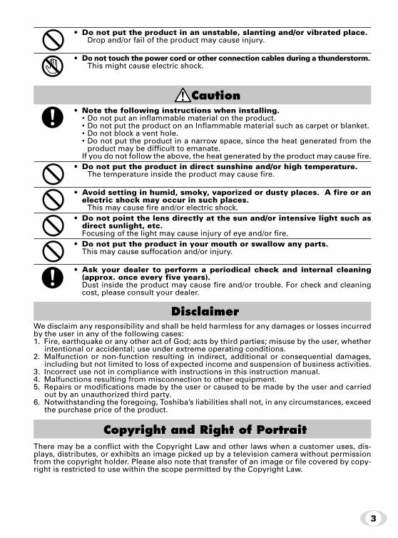
• Do not put the product in an unstable, slanting and/or vibrated place.Drop and/or fail of the product may cause injury.
• Do not touch the power cord or other connection cables during a thunderstorm.This might cause electric shock.
Caution
Disclaimer
• Note the following instructions when installing.• Do not put an inflammable material on the product.• Do not put the product on an Inflammable material such as carpet or blanket.• Do not block a vent hole.• Do not put the product in a narrow space, since the heat generated from the
product may be difficult to emanate.If you do not follow the above, the heat generated by the product may cause fire.
• Do not put the product in direct sunshine and/or high temperature.The temperature inside the product may cause fire.
• Avoid setting in humid, smoky, vaporized or dusty places. A fire or anelectric shock may occur in such places.
This may cause fire and/or electric shock.• Do not point the lens directly at the sun and/or intensive light such as
direct sunlight, etc.Focusing of the light may cause injury of eye and/or fire.
• Do not put the product in your mouth or swallow any parts.This may cause suffocation and/or injury.
• Ask your dealer to perform a periodical check and internal cleaning(approx. once every five years).Dust inside the product may cause fire and/or trouble. For check and cleaningcost, please consult your dealer.
We disclaim any responsibility and shall be held harmless for any damages or losses incurredby the user in any of the following cases:1. Fire, earthquake or any other act of God; acts by third parties; misuse by the user, whether
intentional or accidental; use under extreme operating conditions.2. Malfunction or non-function resulting in indirect, additional or consequential damages,
including but not limited to loss of expected income and suspension of business activities.3. Incorrect use not in compliance with instructions in this instruction manual.4. Malfunctions resulting from misconnection to other equipment.5. Repairs or modifications made by the user or caused to be made by the user and carried
out by an unauthorized third party.6. Notwithstanding the foregoing, Toshiba’s liabilities shall not, in any circumstances, exceed
the purchase price of the product.
Copyright and Right of PortraitThere may be a conflict with the Copyright Law and other laws when a customer uses, dis-plays, distributes, or exhibits an image picked up by a television camera without permissionfrom the copyright holder. Please also note that transfer of an image or file covered by copy-right is restricted to use within the scope permitted by the Copyright Law.

4
TABLE OF CONTENTS
SAFETY PRECAUTIONS ................................................................................. 21. COMPONENTS............................................................................................... 52. SPECIFICATIONS ........................................................................................... 53. NAMES AND FUNCTIONS ............................................................................ 64. CONNECTION ................................................................................................ 8
4.1 An Example of Standard Connection ................................................... 84.2 Cautions on Connection ......................................................................... 84.3 Connection on Back Panel ..................................................................... 94.4 Connector Pin Assignments .................................................................. 9
5. WHEN USING THE CAMERA WITH THE CAMERA UNIT FIXED ............. 106. OPERATION .................................................................................................. 11
6.1 AGC (Automatic Gain Control) ............................................................ 116.2 White Balance ....................................................................................... 11(1) White balance adjustment in modes other than AUTO ................... 12
(1.1) White balance adjustment in SET mode ...................................... 12(1.2) White balance adjustment in MANU mode ................................. 12
6.3 FUNC LOCK Switch .............................................................................. 127. MODE SETTING BY ON SCREEN DISPLAY .............................................. 13
7.1 FILE (Scene File) .................................................................................... 147.2 SHUTTER (Electronic Shutter, Backlight Correction) ........................ 14(1) Detail setting in AUTO mode (auto electronic shutter) .................... 15(2) SS (synchronized scan) ........................................................................ 15
7.3 Pedestal ................................................................................................. 167.4 SYNC (Setting for External Synchronization) ................................... 167.5 AREA (Measurement Area) .................................................................. 17(1) Setting AREA the same for AGC,
auto electronic shutter and white balance ......................................... 17(2) Setting AREA separately for AGC,
auto electronic shutter and white balance ......................................... 187.6 WB-OFFSET (White Balance Offset) ................................................... 197.7 INIT. (Scene File Initialization) ............................................................. 207.8 END (Ending ON SCREEN DISPLAY) .................................................. 20
8 EXTERNAL SYNC ........................................................................................ 219. CAUTIONS ON USE AND INSTALLATION ................................................ 22
10. BEFORE MAKING A SERVICE CALL .......................................................... 2311. OPTIONAL PARTS........................................................................................ 2312. EXTERIOR DIMENSIONS ............................................................................ 24Servicing Instructions for Service Personnel13. Connection to camera Head (IK-M43/IK-C43H) ........................................ 25

5
1. COMPONENTS
(1) Camera control unit .................................................................................. 1
(2) Accessories(a) Instruction manual ............................................................................. 1
2. SPECIFICATIONS
Specification with camera head (IK-M44H) connected.
Power supply DC12V ± 0.5VPower consumption 310 mAImage sensor 1/2 inch IT-CCDEffective pixels Horizontal: 768 pixels, Vertical: 494 pixelsEffective image area Horizontal: 6.54 mm, Vertical: 4.89 mm (1/2 inch type)Scanning system 2:1 interlaceScan frequency Horizontal: 15.734 kHz, Vertical: 59.94 HzSync system Internal/External (automatic switching)Resolution Horizontal: More than 470 lines, Vertical: More than 350 linesStandard intensity of 30 lx (F1.6, 3000K)illumination for objectsMinimum intensity of 2.5 lx (F1.6, 3000K)illumination for objectsS/N ratio 46 dB or more
Video output VBS 1.0 V(p-p), (BNC terminal) NTSC systemY/C separation output (S terminal)
Output impedance 75Ω unbalancedInput VBS 1.0 V(p-p) (BNC terminal) NTSC 75Ω unbalanced
ExternalAdjustment Subcarrier phase, H phasesyncfunction
White balance Automatic/set/manualGain switch (AGC) SENS UP (+6 dB)/ON/OFF
Electronic shutter Automatic, 1/60s, 1/100s, 1/250s, 1/500s, 1/1000s, 1/2000s,1/4000s, 1/10000s, synchronized scan
Operating temperature/ 14°F to 104°F (–10°C to +40°C)/Less than 90%humidityAnti-vibration/ 70 m/s2 (10 to 200 Hz)/700 m/s2shock characteristicsWeight Control unit: 0.86 lbs (390g)Dimensions Control unit: W: 3.35”, H: 1.57”, D: 6.14”(Without protrusion) (W: 85 mm, H: 40 mm, D: 156 mm)
Design and specifications are subject to change without notice.

6
3. NAMES AND FUNCTIONS
Camera Control Unit
CAMERA POWER AGC WB
ONUP AUTO
SET
FUNC
MANUON
OFFOFF
WBSET
R B
DC IN 12V EXT SYNC
REMOTE
FUNC LOCK
S-VIDEO VIDEO
IRIS
ONOFF
5 WB switch
4 AGC switch2 POWER switch
3 POWER indicator
1 CAMERA terminal
6 White balance adjust control
q EXT SYNC terminal
p DC IN 12V terminal
r REMOTE terminal
8 UP button
9 DOWN button
7 FUNC button
e VIDEO terminal
t FUNC LOCK switch
w S-VIDEO terminal
y IRIS terminal

7
1 CAMERA terminal Connects to the camera head.
2 POWER switch Turns on and off the camera control unit.
3 POWER indicator Lights up when the power is turned on.
4 AGC switch Selects the gain mode. (AGC OFF/AGC ON/SENS UP)
5 WB switch Selects the white balance mode. (MANU/SET/AUTO)
6 White balance adjust control Adjusts the R gain and B gain with the white balancemode set to MANU by the WB switch 5.
7 FUNC button Determines the setting indication contents when the set-ting menu is displayed on the screen.
8 UP button Selects the setting item when the setting menu is dis-played on the screen. (When the WB switch 5 is set toSET, pressing the UP button for more than 2 sec. acti-vates the white balance SET operation.)
9 DOWN button Selects the setting item when the setting menu is dis-played on the screen.
p DC IN 12V terminal Accepts a DC power supply (12V).
q EXT SYNC terminal Accepts an external sync signal to synchronize the cam-era output signal with external signal.
w S-VIDEO terminal Connects terminal to S input terminal of a monitor or aVCR, etc.
Can be used at the same time as video terminal.
e VIDEO terminal Connects terminal to video input terminal of a monitoror a VCR, etc.Can be used at the same time with the S-VIDEO termi-nal.
r REMOTE terminal Controls the functions via RS232C.
t FUNC LOCK switch Locks the switches and control on the front panel. Whenthe FUNC LOCK switch is set to ON, all settings exceptfor the POWER switch 2 and the file item of the screensetting menu are locked out.
y IRIS terminal Connect when using an automatic iris lens.
8
4. CONNECTION
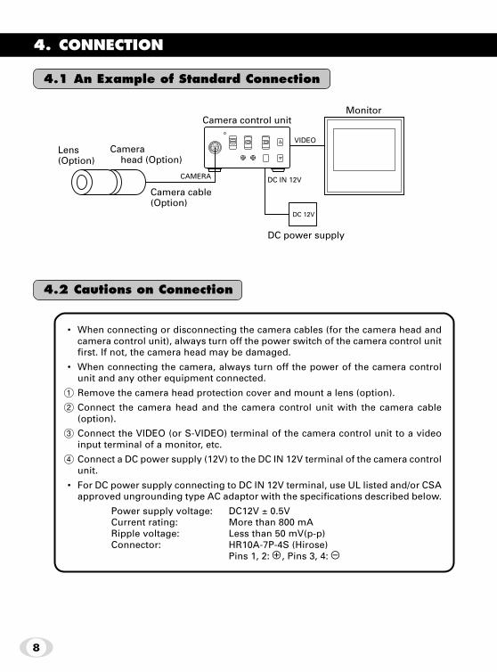
4.1 An Example of Standard Connection
4.2 Cautions on Connection
• When connecting or disconnecting the camera cables (for the camera head andcamera control unit), always turn off the power switch of the camera control unitfirst. If not, the camera head may be damaged.
• When connecting the camera, always turn off the power of the camera controlunit and any other equipment connected.
1 Remove the camera head protection cover and mount a lens (option).
2 Connect the camera head and the camera control unit with the camera cable(option).
3 Connect the VIDEO (or S-VIDEO) terminal of the camera control unit to a videoinput terminal of a monitor, etc.
4 Connect a DC power supply (12V) to the DC IN 12V terminal of the camera controlunit.
• For DC power supply connecting to DC IN 12V terminal, use UL listed and/or CSAapproved ungrounding type AC adaptor with the specifications described below.
Power supply voltage: DC12V ± 0.5VCurrent rating: More than 800 mARipple voltage: Less than 50 mV(p-p)Connector: HR10A-7P-4S (Hirose)
Pins 1, 2: e, Pins 3, 4: d
Lens(Option)
Camera head (Option)
Camera control unit
Camera cable(Option)
Monitor
CAMERA
VIDEO
DC IN 12V
DC power supply
DC 12V
9
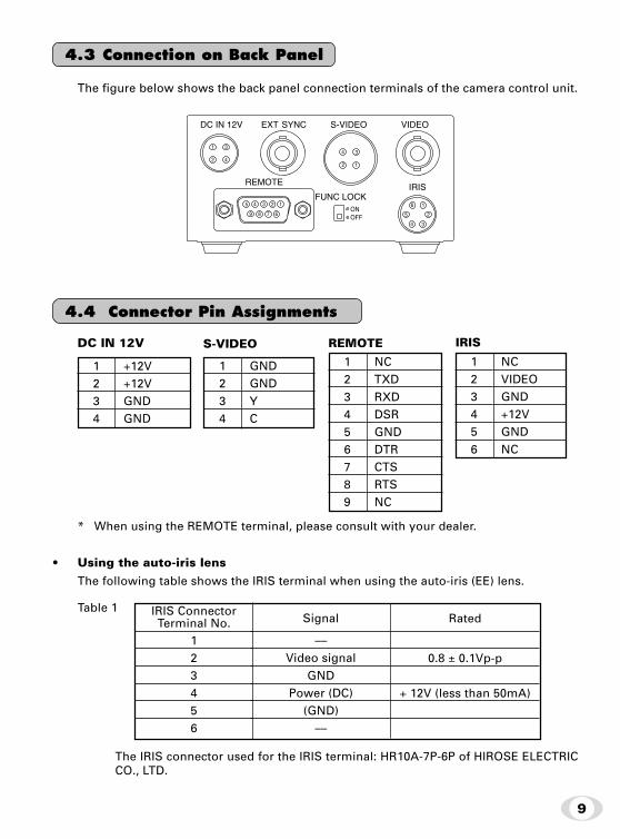
4.3 Connection on Back Panel
The figure below shows the back panel connection terminals of the camera control unit.
1234
+12V+12VGNDGND
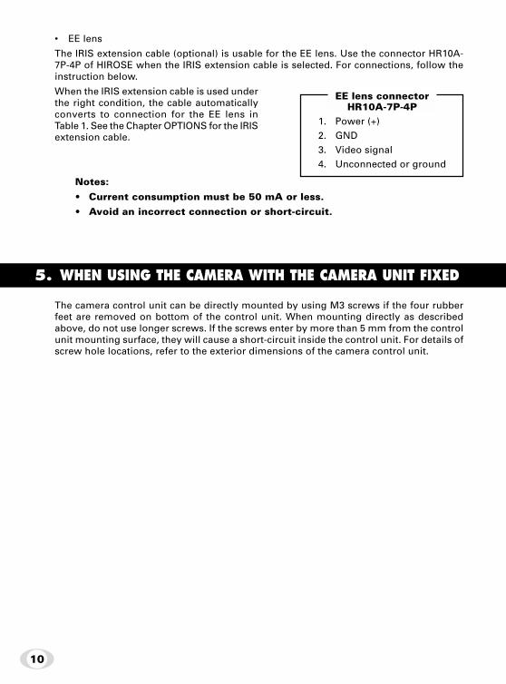
4.4 Connector Pin Assignments
123456789
NCTXDRXDDSRGNDDTRCTSRTSNC
1234
GNDGNDYC
123456
NCVIDEOGND+12VGNDNC
DC IN 12V EXT SYNC S-VIDEO
REMOTE
VIDEO
FUNC LOCKONOFF
12345
6789
1
2
3
412
34
IRIS
25
16
34
IRISREMOTEDC IN 12V S-VIDEO
* When using the REMOTE terminal, please consult with your dealer.
• Using the auto-iris lens
The following table shows the IRIS terminal when using the auto-iris (EE) lens.
Table 1
The IRIS connector used for the IRIS terminal: HR10A-7P-6P of HIROSE ELECTRICCO., LTD.
Signal
––Video signal
GNDPower (DC)
(GND)––
IRIS ConnectorTerminal No.
123456
Rated
0.8 ± 0.1Vp-p
+ 12V (less than 50mA)
10
• EE lens
The IRIS extension cable (optional) is usable for the EE lens. Use the connector HR10A-7P-4P of HIROSE when the IRIS extension cable is selected. For connections, follow theinstruction below.
When the IRIS extension cable is used underthe right condition, the cable automaticallyconverts to connection for the EE lens inTable 1. See the Chapter OPTIONS for the IRISextension cable.
Notes:
• Current consumption must be 50 mA or less.• Avoid an incorrect connection or short-circuit.
5. WHEN USING THE CAMERA WITH THE CAMERA UNIT FIXED
The camera control unit can be directly mounted by using M3 screws if the four rubberfeet are removed on bottom of the control unit. When mounting directly as describedabove, do not use longer screws. If the screws enter by more than 5 mm from the controlunit mounting surface, they will cause a short-circuit inside the control unit. For details ofscrew hole locations, refer to the exterior dimensions of the camera control unit.
EE lens connectorHR10A-7P-4P
1. Power (+)2. GND3. Video signal4. Unconnected or ground

11
6. OPERATION
Turn on the POWER switch on the camera control unit and adjust the lens iris and focuswhile observing a picture on the monitor screen. To obtain the best picture quality, per-form various settings.
6.1 AGC (Automatic Gain Control)
AGC functions “OFF”, “ON” or “UP” can be selected on the screen menu. Generally, thecamera is used with the AGC set to OFF, but when increased camera sensitivity is re-quired, it is set to ON. When more sensitivity is required, “UP” is selected. With the AGCON, the camera sensitivity approximately doubles, and with the UP selected the sensitiv-ity approximately doubles again, but noise will also increase. We recommend you in-crease intensity of the lighting to obtain good pictures.
The AGC measurement area is the same as that used for “AREA”. (Refer to item 7.5)
6.2 White Balance
A white balance adjustment is necessary to obtain pictures with correct color tone. Thiscamera allows you to select the white balance adjustment of “AUTO”, “SET”, and“MANU”. With the AUTO mode selected, the camera adjusts the white balance automati-cally. Most shooting will be made in the AUTO mode. The color temperature applicable tothis camera is approximately 2500 to 7000K.
Outline
Features
Notes
AUTOCamera automati-cally measuresobject colortemperature andadjusts the whitebalance.Automatically tracesvariations of colortemperature andadjusts the whitebalance.
Under poor illumina-tion, white balancemay not be correct.
SETAdjust white balanceby pressing “UP”button on thecamera control unitwhile shooting awhite object.Measurementaccuracy is higherthan AUTO mode.This mode iseffective whenshooting under lessvariations of colortemperature.
MANUAdjust R (red) and B(blue) levels on thecontrol unit whileshooting a whiteobject.
Measurementaccuracy is higherthan SET mode.This mode iseffective for usersdesiring specificcolor temperature,also effective whenshooting under theleast variations ofcolor temperature.Adjustment will bemade by viewingmonitor or vectorscope.

12
(1) White balance adjustment in modes other than AUTO
(1.1) White balance adjustment in SET mode1 Set the WB switch to “SET” position.
2 Shoot a white object to fill entire screen and press the UP button ( , ) for about 2sec.
3 When the white balance adjustment completes, the letters “WB SET” blinking atthe upper right of the screen changes to “WB OK” and then turns off. If the “WBNG” is displayed, it shows the white balance is out of the adjustment range. Thisis caused by the object not being white enough, or the video level is set too highor too low even if the white object is shot. Shoot the white object or set the videolevel correctly.
Note:• With the screen menu displayed, the UP button is used for moving the
cursor or modifying the data. To activate the SET mode by pressing theUP button, turn off the screen menu.
(1.2) White balance adjustment in MANU mode1 Set the WB switch to “MANU” position.
2 Shoot the white object and adjust the white balance by adjusting the white bal-ance adjust controls “R” and “B” with the screwdriver while observing the moni-tor or vector scope.
6.3 FUNC LOCK Switch
The FUNC LOCK switch protects settings even if aswitch is accidentally pressed after setting. Whenthe FUNC LOCK switch is ON, only the followingfunctions are available.
POWER switch (ON/OFF)
FILE (A/B) in menu
Settings will not be changed even if the otherswitches are operated. In the menu screen, all ex-cept FILE and END are displayed in black letters(white when the FUNC LOCK switch is OFF) and“FUNCTION LOCK ACTIVE” blinks to indicate thatthe FUNC LOCK switch is ON.
7. Mode Setting by Display7.
SHUTTER AUTO
FILE A
PEDESTAL 00
SYNC INT
AREA LINK:1
WB-OFFSET 00
INIT.
END
FUNCTION LOCK ACTIVE
PUSH FUNC TO SELECT
13
7. MODE SETTING BY ON SCREEN DISPLAY
Setting while monitoring the menu on the monitor screen is possible. The following sevenitems can be set.
1 Scene file
2 Electronic shutter (AUTO/MANUAL), backlight correction
3 Pedestal level
4 Phase matching in external synchronization (horizontal/subcarrier synchronization)
5 White balance, auto electronic shutter, AGC measurement area
6 White balance offset
7 Scene file factory setting
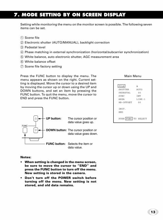
Press the FUNC button to display the menu. Themenu appears as shown on the right. Current set-ting is displayed. Move the cursor to a desired itemby moving the cursor up or down using the UP andDOWN buttons, and set an item by pressing theFUNC button. To quit the menu, move the cursor toEND and press the FUNC button.
Notes:• When setting is changed in the menu screen,
be sure to move the cursor to “END” andpress the FUNC button to turn off the menu.New setting is stored in the camera.
• Don’t turn off the POWER switch beforeturning off the menu. New setting is notstored, and old data remains.
Main Menu
SHUTTER AUTO
FILE A
PEDESTAL 00
SYNC INT
AREA LINK:1
WB-OFFSET 00
INIT.
END
PUSH FUNC TO SELECT
FUNC
UP button: The cursor position ordata value goes up.
The cursor position ordata value goes down.
Selects the item ordata value.
DOWN button:
FUNC button:

14
7.1 FILE (Scene File)
There are two scene files A and B which can be se-lected according to the shooting state.
1 Move the cursor to “FILE” in the main menu us-ing the UP or DOWN button.
2 Press the FUNC button to display the contents toset FILE, A or B. Move the cursor to A or B usingthe UP or DOWN button. Press the FUNC buttonto set the contents.
Note:
• The scene file is for the menu screen. TheAGC switch and the WB switch are onlyvalid in their set positions.
• The new settings are memorized when thePOWER is turned off.
SHUTTER AUTO
FILE A
PEDESTAL 00
SYNC INT
AREA LINK:1
WB-OFFSET 00
INIT.
END
PUSH FUNC TO SELECT
7.2 SHUTTER (Electronic Shutter, Backlight Correction)
The electronic shutter is available in AUTO (autoelectronic shutter), 1/60 ~ 1/10000 and SS (synchro-nized scan).
AUTO: Controls electronic shutter automati-cally to output the set video level. Canbe selected in backlight correction,peak measurement, average mea-surement and measurement area.
1/60~1/10000: Exposure time can be fixed to any oneof 1/60, 1/100, 1/250. 1/500, 1/1000,1/2000, 1/4000 and 1/10000.
SS: Sets the electronic shutter in horizon-tal scanning time intervals of 1H.
1 Move the cursor to “SHUTTER” in the main menuusing the UP or DOWN button.
2 Press the FUNC button to display AUTO ~ EXITto set SHUTTER. Move the cursor to a desireditem of AUTO ~ SS using the UP or DOWN but-tons. Press the FUNC button to frame a desireditem in white.
3 Move the cursor to “EXIT” using the UP or DOWNbutton. Press the FUNC button. Return to themain menu.
SHUTTER AUTO
FILE A
PEDESTAL 00
SYNC INT
AREA LINK:1
WB-OFFSET 00
INIT.
END
PUSH FUNC TO SELECT
SHUTTER B
FILE A
PEDESTAL
SYNC
AREA
WB-OFFSET
INIT.
END
PUSH FUNC TO SELECT
SHUTTER
FILE
1/100
1/60
1/500
1/1000
1/2000
1/4000
1/10000
1/250
262/525H
PEDESTAL
SYNC
AREA
WB-OFFSET
INIT.
END SS
EXIT
PUSH FUNC TO SUB MENU
AUTO

15
(1) Detail setting in AUTO mode (auto electronic shutter)
When the FUNC button is pressed after AUTO is se-lected, the submenu for SHUTTER:AUTO appears.Set details in this screen.
LEVEL: Adjust the auto electronic shuttervideo level. Larger values indicatesbrighter level, and vice versa. Data canbe set in a range of –30 to +30.
BLC: Correction for backlight. This can beset when the measurement area is setto one of “1/2”, “1/8” and “SLIT” forAREA in the main menu. Backlight iscorrected at ON, but not at OFF. Whenthe measurement area is “1”, BLC isdisplayed in black letters and settingis impossible.
PEAK:AVE: Selects peak or average for measure-ment of auto electronic shutter videolevel. The peak to average ratio canbe changed in a range of 00:10 to10:00.
Note:• While BLC is ON, PEAK:AVE is displayed in
black letters and setting is impossible.
1 Move the cursor to a desired item (LEVEL, BLC,PEAK:AVE) using the UP or DOWN button. Pressthe FUNC button. The cursor moves to the dataof the selected item. Set the data by pressing theUP or DOWN button.
2 After setting the data, press the FUNC button. Thecursor moves to the item. To finish setting ofsubmenu, move the cursor to “EXIT” and pressthe FUNC button to return to “SHUTTER” in themain menu.
(2) SS (synchronized scan)
1 Move the cursor to “SS” using the UP or DOWNbutton. Press the FUNC button. (SS is set.)
2 Press the FUNC button. The cursor moves to thedata and blinks. The data varies in 1/525H to 262/525H when the UP or DOWN button is pressed.Set a desired data, and press the FUNC button.
3 Return to “SS” of SHUTTER.
SHUTTER
FILE
1/100
1/60
1/500
1/1000
1/2000
1/4000
1/10000
1/250
262/525H
PEDESTAL
SYNC
AREA
WB-OFFSET
INIT.
END SS
EXIT
PUSH FUNC TO SUB MENU
AUTO
LEVEL 00
BLC OFF
PEAK:AVE 00:10
EXIT
PUSH FUNC TO SELECT
UTHS TER:AUTO SUB MENU
LEVEL 00
BLC
PEAK:AVE
EXIT
PUSH FUNC TO SELECT
UTHS TER:AUTO SUB MENU
Example of display for LEVEL
SHUTTER
FILE
1/100
1/60
1/500
1/1000
1/2000
1/4000
1/10000
1/250
262/525H
PEDESTAL
SYNC
AREA
WB-OFFSET
INIT.
END SS
EXIT
PUSH FUNC TO SELECT
AUTO

16
7.3 Pedestal
1 Move the cursor to PEDESTAL using the UP orDOWN button.
2 Press the FUNC button. The cursor moves to thedata. Set the data using the UP or DOWN button.The data can be set in a range of –50 to +50. Aftersetting the data, press the FUNC button to returnto the main menu.
This adjusts horizontal phase and subcarrier phasewhile externally synchronized. INT is displayed forinternal synchronization and changed automaticallyto EXT when the external synchronizing signal is en-tered.
1 Move the cursor to “SYNC” using the UP orDOWN button.
2 Press the FUNC button to display the availableitems (H-PHS, SC-PHS, SC-FINE).
H-PHS: H (horizontal) phase matching 0 ~ 99
SC-PHS: SC (subcarrier) rough adjustment 0,90, 180, 270
SC-FINE: SC (subcarrier) fine adjustment 0 ~ 99
7.4 SYNC (Setting for External Synchronization)
SHUTTER AUTO
FILE A
PEDESTAL 00
SYNC INT
AREA LINK:1
WB-OFFSET 00
INIT.
END
PUSH FUNC TO SELECT
SHUTTER
FILE
PEDESTAL 00
SYNC
AREA
WB-OFFSET
INIT.
END
PUSH FUNC TO SELECT
SHUTTER AUTO
FILE A
PEDESTAL 00
SYNC INT
AREA LINK:1
WB-OFFSET 00
INIT.
END
PUSH FUNC TO SELECT
SHUTTER AUTO
FILE A
PEDESTAL 00
SYNC EXT.VBS
AREA LINK:1
WB-OFFSET 00
INIT.
END
PUSH FUNC TO SELECT

17
1 Move the cursor to LINK using the UP or DOWNbutton.
3 Move the cursor to a desired item (H-PHS, SC-PHS, SC-FINE) using the UP or DOWN button.Press the FUNC button and the data is displayed.Set the data using the UP or DOWN button andpress the FUNC button to select the data. To re-turn to the main menu, move the cursor to EXITand press the FUNC button.
Note:
• If the internal synchronization is set whilethe SYNC item (H-PHS, SC-PHS, SC-FINE) isbeing displayed, the display automaticallyturns to INT, disabling setting.
SHUTTER
FILE
PEDESTAL
SYNC H-PHS
AREA SC-PHS
WB-OFFSET SC- FINE
EXIT
INIT.
END
PUSH FUNC TO SELECT
50
0
50
7.5 AREA (Measurement Area)
AREA is a measurement AREA item for AGC, autoelectronic shutter and white balance. The AREA set-ting for AGC and auto electronic shutter are thesame, so each setting can not be made separately.However, the AREA setting for white balance canbe made independently from the AREA setting forAGC and auto electronic shutter.
1 Move the cursor to AREA using the UP or DOWNbutton.
2 Press the FUNC button to display the availableitems (LINK, SEP).
3 Move the cursor to a desired item (LINK, SEP)using the UP or DOWN button.
(1) Setting AREA the same for AGC, auto electronic shutter and
white balance
SHUTTER
FILE
PEDESTAL
SYNC
AREA LINK:1
WB-OFFSET SEP
EXIT
INIT.
END
PUSH FUNC TO SELECT
SHUTTER AUTO
FILE A
PEDESTAL 00
SYNC INT
AREA LINK:1
WB-OFFSET 00
INIT.
END
PUSH FUNC TO SELECT

18
2 Press the FUNC button to display data 1 ~ SLITfor LINK. Move the cursor to a desired item ofAREA data (1, 1/2, 1/8, SLIT) using the UP orDOWN button.
3 Press the FUNC button to set the data.
(2) Setting AREA for white balance separately from the AREA
setting for AGC and auto electronic shutter
1 Move the cursor to SEP using the UP or DOWNbutton, and press the FUNC button. SEP is se-lected and framed in white.
2 Press the FUNC button to display the submenu.
3 Move the cursor to a desired item using UP orDOWN button.
WB: Measurement AREA for white balance1, 1/2, 1/8, SLITValid when the WB switch is AUTOand/or SET.
SHUTTER: Measurement AREA for auto elec-tronic shutter and AGC1, 1/2, 1/8, SLIT
4 Press the FUNC button to select a desired item.The setting data (1, 1/2, 1/8, SLIT) is displayed.Move the cursor to a desired item using UP orDOWN button, then press the FUNC button toselect the data.
5 The submenu for AREA appears. Move the cur-sor to EXIT, and press the FUNC button to returnto the main menu.
The size of AREA is approximately as shown below.
SHUTTER
FILE
PEDESTAL
SYNC
AREA LINK 1
WB-OFFSET SEP
EXIT
INIT. SLIT
END
PUSH FUNC TO SELECT
1/2
1/8
SHUTTER
FILE
PEDESTAL
SYNC
AREA LINK:1
WB-OFFSET SEP
EXIT
INIT.
END
PUSH FUNC TO SELECT
WB 1
AREA:SEP SUB MENU
SHUTTER 1
EXIT
PUSH FUNC TO SELECT
WB 1
AREA:SEP SUB MENU
SHUTTER
EXIT
SLIT
PUSH FUNC TO SELECT
1/2
1/8
(1) 1 (Whole monitor screen) (2) 1/2
(3) 1/8 (4) SLIT
61
H 64
H 61
H
81
V
81
V
86
V
81
V
86
V
81
V
62.5
2.5
2.5
H 61
H31
H 31
H 31
H
8 V
83
V
8 V
62.5
H

19
7.6 WB-OFFSET (White Balance Offset)
This offsets the white balance in the direction oforange or cyan when the WB switch is set to “SET”.
1 Move the cursor to WB-OFFSET using the UP orDOWN button.
2 Press the FUNC button. The cursor moves to thedata item.
3 Change the data using the UP or DOWN button.
+20 ~ –20
+ Orange direction
– Cyan direction
Press the FUNC button at a desired data value toset the data.
SHUTTER AUTO
FILE A
PEDESTAL 00
SYNC INT
AREA LINK:1
WB-OFFSET 00
INIT.
END
PUSH FUNC TO SELECT
SHUTTER
FILE
PEDESTAL
SYNC
AREA
WB-OFFSET 00
INIT.
END
PUSH FUNC TO SELECT

20
SHUTTER AUTO
FILE A
PEDESTAL 00
SYNC INT
AREA LINK:1
WB-OFFSET 00
INIT.
END
PUSH FUNC TO SELECT
SHUTTER
FILE A
PEDESTAL
SYNC
AREA
WB-OFFSET
INIT. NO
END YES
PUSH FUNC TO SELECT
7.7 INIT. (Scene File Initialization)
This reset settings of the scene file to the factorysetting.
1 Select a scene file (A or B) to initialize the settingin FILE.
2 Move the cursor to INIT. using the UP or DOWNbutton.
3 Press the FUNC button. The selected scene file(A or B) is displayed. NO/YES is displayed.
4 Select NO when not initializing. Select YES andpress the FUNC button when initializing.
Factory setting (the following setting if INIT. is executed)
The setting is common to scene files A and B.
7.8 END (Ending ON SCREEN DISPLAY)
To turn off the menu, move the cursor to END usingthe UP or DOWN button and press the FUNC but-ton. To store the setting in the camera, be sure toturn off the display by pressing END. When the dis-play is turned off, the setting is stored in the cam-era. If the POWER switch is turned off while the menuis being displayed, the setting is not stored and theold data remains.
SHUTTER AUTO
FILE A
PEDESTAL 00
SYNC INT
AREA LINK:1
WB-OFFSET 00
INIT.
END
PUSH FUNC TO SELECT
AUTO 00EXT.VBSLINK:1 00
SEP WB 1 SHUTTER 1
H-PHS 50SC-PHS 0SC-FINE 50
SHUTTERPEDESTALSYNCAREA
WB-OFFSET
LEVEL 00BLC OFFPEAK:AVE 00:10
21
External sync. signal
Camera video output
Match the phase.
8. EXTERNAL SYNC
When using the camera with external sync, connect a composite video signal (C-VIDEO)to the EXT SYNC terminal on back of the camera control unit. When the camera acceptsexternal sync, it is automatically switched from the internal sync to the external sync.
(1) External sync signal input conditions
C-VIDEO : SYNC section 0.3 ± 0.1V
(75Ω unbalanced) BURST section 0.3 ± 0.1V
(2) External sync frequency range
Within ±50 ppm in reference to NTSC standard frequency
(H frequency 15733.5 Hz to 15735.0 Hz)
(3) Using the camera with external sync signal
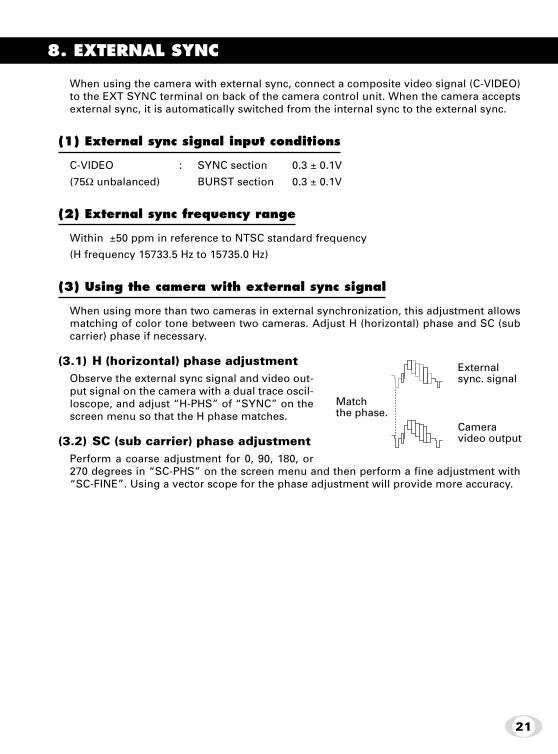
When using more than two cameras in external synchronization, this adjustment allowsmatching of color tone between two cameras. Adjust H (horizontal) phase and SC (subcarrier) phase if necessary.
(3.1) H (horizontal) phase adjustmentObserve the external sync signal and video out-put signal on the camera with a dual trace oscil-loscope, and adjust “H-PHS” of “SYNC” on thescreen menu so that the H phase matches.
(3.2) SC (sub carrier) phase adjustmentPerform a coarse adjustment for 0, 90, 180, or270 degrees in “SC-PHS” on the screen menu and then perform a fine adjustment with“SC-FINE”. Using a vector scope for the phase adjustment will provide more accuracy.

22
9. CAUTIONS ON USE AND INSTALLATION
Carefully handle the units.Do not drop, or give a strong shock or vi-bration to the camera. This may causeproblems. Treat the camera cables care-fully to prevent cable problems, such ascable breakdown and loosened connec-tions.
Do not shoot intense light.If there is an intense light at a location onthe screen such as a spot light, a bloom-ing and smearing may occur. When in-tense light enters, vertical stripes mayappear on the screen. This is not a mal-function. Ghosts may occur when thereis an intense light near the object. In thiscase, change the shooting angle.
Install the camera in a location freefrom noise.If the camera or the cables are locatednear power utility lines or a TV, etc. unde-sirable noise may appear on the screen.In such a case, try to change the locationof the camera or the cable wiring.
MoireWhen thin stripe patterns are shot, stripepatterns that are not actually there (moire)may appears as interference stripes. Thisis not a malfunction.
Operating ambient temperature andhumidity.Do not use the camera in places wheretemperature and humidity exceed thespecifications. Picture quality will lowerand internal parts may be damaged.
Be particularly careful when using inplaces exposed to direct sunlight. Whenshooting in hot places, depending on theconditions of the object and the camera(for example when the gain is increased),noise in the form of vertical strips or whitedots may occur. This is not a malfunc-tion.
Handling of the protection cap.Keep the protection cap away from chil-dren. Children may put them into mouthor swallow them accidentally. The protec-tion cap protects the image sensing planewhen the lens is removed from the cam-era, do not throw away.
When not using the camera for a long-time.Stop supplying power.
When cleaning the cameraAlways turn off the power and clean witha piece of soft dry cloth. Do not use ben-zine, alcohol, thinner, household deter-gents, chemically treated cloths, etc. Ifused, coating and printed letters may bediscolored. When cleaning the lens, usea lens cleaning paper, etc.
Avoid using or storing the camera in thefollowing places:Places filled with highly flammable gas.
Places near gasoline, benzene, or paintthinner.
Places subject to strong vibration.
Places contacting chemicals (such as pes-ticides), rubber or vinyl products for a longperiod of time.

23
10. BEFORE MAKING A SERVICE CALL
SymptomNo picture
Poor color
“HEAD UNCONNECTED”or “CABLE DETECT ERR”is displayed on the screen
Items to be checked• Is the power supplied correctly?• Is the lens iris adjusted correctly?• Are the cables connected correctly?• Is the monitor (TV) adjusted correctly?• Is the white balance of the camera adjusted correctly?
(in modes other than automatic trace)• Is the illumination dark?• Is the SC phase adjusted correctly? (External sync)• Turn the power of the camera off, make proper connec-
tion for the camera head, camera cable, and cameracontrol unit, and then turn the power on again. (Im-proper connection may cause the trouble.)
11. OPTIONAL PARTS
For further details, call the dealers.
Camera head
Type nameIK-SM43HIK-C44HIK-M44H
IK-UM44H
7mm Camera headC mount head
17mm Camera head12mm Camera head

24
12. EXTERIOR DIMENSIONS
Camera Control Unit
Unit : mm [inch]
85[3.35]
11 [0.43]
40 [
1.57
]
20 [
0.79
]
10.5[0.41]
28 [
1.10
]
10 [
0.39
]
9 [0
.35]
26.5
[1.
04]
63[2
.48]
3.9[0.15]
3.9
[0.1
5]
20[0.79]
21.5[0.85]
24.5[0.96]
24[0.94]
19[0.75]
21.5[0.85]
27[1.06]
114[4.49]
CAMERA POWER AGC WB
ONUP AUTO
SET
FUNC
MANUON
OFFOFF
WBSET
R B
DC IN 12V EXT SYNC
REMOTE
FUNC LOCK
S-VIDEO VIDEO
ONOFF
7 [0.28]
156[6.14]
φ12[0.47]
4-M3 pitch 0.5Threaded hole
10.8[0.43]
IRIS

25
(2)
(3)
(1)
13. Connection to Camera Head (IK-M43H/IK-C43H)
When connecting to the camera head (IK-M43H/IK-C43H), select the internal switch insidethe camera controller following to the procedures below.
1 After turning off the power, remove all thecables connected to the camera control-ler.
2 Remove three screws on the bottom chas-sis of the camera control unit to removethe internal unit.
3 Turn off No. 3 of S101 switch located onthe component side of the internal circuitunit PC board.
No3 of S101switch
OFF
ON
Applicable camera head to connect
IK-M43HIK-CN43HIK-M44HIK-C44H
IK-UM44HIK-SM44HIK-SM45H
Note: Do not change the switch settingsother than S101. If you change the set-tings, the normal image may not beobtained.
4 Perform the reverse procedures to as-semble.
H101S101
Q503
Q508
P101
ON OFF
Servicing Instructions forService Personnel
Fro
nt
Sid
e
Rea
r S
ide

26

27

28
LIMITED WARRANTY
Printed in Japan 23552119
Promptly register your product with Toshiba on-line at www.toshiba.com/taisisd. By registering your productyou will be eligible for periodic updates, announcements, and special offers. You will have access to extended warrantyoptions, upgrades (as applicable), useful tips, on-line troubleshooting, and the ability to schedule service on-line ifnecessary. The Imaging Systems Division of Toshiba America Information Systems, Inc. ("ISD") makes the followinglimited warranties. These limited warranties extend to the Original End-User ("Your[r]").
Limited One (1) Year Warranty of Labor and PartsISD warrants this product and parts against defects in material or workmanship for a period of one year from the dateof original retail purchase by the end-user. During this period, ISD will repair or replace a defective product or part witha new or refurbished item. The user must deliver the entire product to an ISD authorized service center. The user isresponsible for all transportation and insurance charges for the product to the Service Center. ISD reserves the right tosubstitute Factory Refurbished Parts and / or Factory Refurbished Product in place of those in need of repair.
Step-by-step Procedures - How to Obtain Warranty Service[1] Verify operation of the unit by checking the instruction manual[2] If there is a defect in material or workmanship, contact an Authorized Service Provider within 30 days after theproduct fails to comply with specifications.[3] Arrange for delivery of the product to the ISD authorized service center. Products must be insured and securelypacked, preferably in the original shipping carton. A letter explaining the defect and a copy of the bill of sale or otherproof of purchase must be enclosed with a complete return street address and daytime telephone number. Charges fortransportation and insurance must be prepaid by the end-user.
Questions? If you have any questions, please check the Toshiba Imaging Systems Division Web site asfollows:
Website: http://www.toshiba.com/taisisd/indmed
Your Responsibility, warranties are subject to the following conditions:[1] You must retain the bill of sale or provide other proof of purchase.[2] You must schedule service within thirty days after you discover a defective product or part.[3] All warranty servicing of this product must be made by a Toshiba ISD Authorized Service Provider.[4] The warranty extends to defects in material or workmanship as limited above, and not to any products or parts thathave been lost or discarded by user. The warranty does not cover damage caused by misuse, accident, improperinstallation, improper maintenance, or use in violation of instructions furnished by ISD. The warranty does not extend tounits which have been altered or modified without authorization of ISD, or to damage to products or parts thereof whichhave had the serial number removed, altered defaced or rendered illegible.
ALL WARRANTIES IMPLIED BY STATE LAW, INCLUDING THE IMPLIED WARRANTIES OF MERCHANTABILITYAND FITNESS FOR A PARTICULAR PURPOSE, ARE EXPRESSLY LIMITED TO THE DURATION OF THE LIMITEDWARRANTIES SET FORTH ABOVE. Some states do not allow limitations on how long an implied warrantylasts, so the above limitation may not apply. WITH THE EXCEPTION OF ANY WARRANTIES IMPLIED BY STATELAW AS HEREBY LIMITED, THE FOREGOING EXPRESS WARRANTY IS EXCLUSIVE AND IN LIEU OF ALL OTHERWITH RESPECT TO THE REPAIR OR REPLACEMENT OF ANY PRODUCTS OR PARTS. IN NO EVENT SHALLISD BE LIABLE FOR CONSEQUENTIAL OR INCIDENTAL DAMAGES. Some states do not allow the exclusion orlimitation of incidental or consequential damages so the above limitation may not apply.
No person, agent, distributor, dealer, service station or company is authorized to change, modify or extendthe terms of these warranties in any manner whatsoever. The time within which an action must be com-menced to enforce any obligation of ISD arising under this warranty or under any statute, or law of the UnitedStates or any state thereof, is hereby limited to one year from the date you discover or should have discov-ered, the defect. This limitation does not apply to implied warranties arising under state law. Some states donot permit limitation of the time within which you may bring an action beyond the limits provided by state lawso the above provision may not apply to user. This warranty gives the user specific legal rights, and user mayalso have other rights, which may vary from state to state.
TOSHIBA AMERICA INFORMATION SYSTEMS, INC.Imaging Systems DivisionCopyright © 2002 Toshiba America, Inc. All rights reserved.