i/i WRIGHT AERONAUTICAL LABS NRIGHT-PATTERSON AFB … · design criteria were needed for the newer,...
75
AD~i~e682 AFIALFY81 TECHNICAL ACCOMPLISHMENTSMU AIR FORCE i/i WRIGHT AERONAUTICAL LABS NRIGHT-PATTERSON AFB OH R S HOFF APR 82 RFWRL-TR-82-BBFn CAUNCLASSIFIED F/G 1/3 1N *EE7
Transcript of i/i WRIGHT AERONAUTICAL LABS NRIGHT-PATTERSON AFB … · design criteria were needed for the newer,...

AD~i~e682 AFIALFY81 TECHNICAL ACCOMPLISHMENTSMU AIR FORCE i/iWRIGHT AERONAUTICAL LABS NRIGHT-PATTERSON AFB OHR S HOFF APR 82 RFWRL-TR-82-BBFn
CAUNCLASSIFIED F/G 1/3 1N
*EE7

1. LA L2A L2I 5
u AU)82 vah~ M 1 22
. . .. .. 3- '1 I -, I _ J [ -I
W 2 -10
1 .*.25 14 16
1.53.4l 11.6
MICROCOPY RESOLUTION TEST CHARTNATO% BUREAU OF STANDANS6-]963-A
MICROCOPY RESOLUTION TEST CHART B
NATI NAL BUREAU OF STANDARD
S-I963-A
1.1. w __22.
"" 1 ___ ____i___ ""_
MICROCOPY RESOLUTION TEST CHARTNATIONAL BUREAU OF STANDARDS-63-A ..
,11 , 1. ,,, 4 ... *1H 1.011 ___.
M" "'W i2i.
Ilttw--w W 1 2.0.. : bJ..O II~ .
MICROCOPY RESO UTI* ,S- C","MICROCOPY RESOLUTION TEST CHARY
B EM OF SOLtIV TT .-
.ATM BUREAU OF SY-ADAVS1963-A
• • •.• - - "-..
.,.. . .•...
AFWALTR424MI
AFWAL FY61 TECHNICA ACCOMPLISHENTS
Road S. Hoff, Jr.
414 Programs Branch-~ ~ Plans and Programs Office
S Directorate of Management Services
FWAL UP O FOPCAL YEAR IM1
Approv-d for pisbkc roloon-; dbtrlbvlloe unNmd
<.OCT 25 S-82
LU-__.j AIR FORCE WRIGHT AERONAUTICAL LABORATORIEM
ML. I FORCE SYSTMS COWMMWRIHT-AWERSON AIR FORCE SE, OHIO 45W3
82 10 2 5 04t
'
NOTICE
When Government drawings, specifications, or other data are used for any purposeot e than in connection with a definitely related Government procurement operation,he nited States Government thereby incurs no responsibility nor any obligationwha oever; and the fact that the government may have formulated, furnished, or inan way supplied the said drawings, specifications, or other data, is not to be re-gaded by implication or otherwise as in any manner licensing the holder or any
other person or corporation, or conveying any rights or permission to manufactureuse, or sell any patented invention that may in any way be related thereto.
This report has been reviewed by the Office of Public Affairs (ASD/PA) and isreleasable to the National Technical Information Service (NTIS). At NTIS, it willbe available to the general public, including foreign nations.
This technical report has been reviewed and is approved for publication.
RUSSELL S. HOFF, Jr.Inteqrated Programs Group
*, Denuty Director of Manaqerent ServicesAF Wright Aeronautical Laboratories
"If your address has changed, if you wish to be removed from our mailing list, or* If the addressee is no longer employed by your organization please notify AFTI',LIXfPI,* W-PAFB, OH 45433 to help us maintain a current mailing list".
Id Copies of this report should not be returned unless return is required by securityconsiderations, contractual obligations, or notice on a specific document.
. . ., ..- . .. * .

UnclassifiedSECURITY CLASSIFICATION OF THIS PAGE (When Data Entered)
READ INSTRUCTIONSREPORT DOCUMENTATION PAGE BEFORE COMPLETING FORMIREPORT NUMBER 2GOT ACCESSION No. 3. RECIPIENT'S CATALOG NUMBER
AFWAL-TR-82-OO1 -A f~Q~4. TITLE (and Subtitle) S. TYPE OF REPORT & PERIOD COVERED
Final Technical Report FY81AFWAL FY81 Technical Accomplishments S. PERFORMING 01G. REPORT NUMBER
7. AUTI4OR(e) S. CONTRACT OR GRANT NUMBER(#)
Russell S. Hoff Jr.
S. PERFORMING ORGANIZATION NAME AND ADDRESS O.PROGRAM ELEMENT. PROJECT. TASKAREA & WORK UNIT NUMBERSPrograms Branch (XRP)
Air Force Wright Aeronautical LaboratoriesWright-PattersonAir Force Base OH 45433 ______________
II. CONTROLLING OFFICE NAME AND ADDRESS 12. REPORT DATE
Directorate of Management Services (GL) April 1982Air Force Wright Aeronautical Laboratories 13. NUMBER OF PAG~ESWright-Patterson Air Force Base OH 45433 7 3
14. MONITORING AGENCY NAME & ADORESS(f different from Controlling Olfie*) IS. SECURITY CLASS. (of this report)
Unclassifiled
Ise. DECLASSI FICATION/ DOWNGRADINGSC EDU LIE
Is. DISTRIBUTION STATEMENT (of this Report)
Approved for public release; distribution unlimited.
17. DISTRIBUTION STATEMENT (of the abstrten tered In Block 20, If different from, Report)
Is. SUPPLEMENTARY NOTES
I9. KEY WORDS (Continue on tower*& side It necessary and identity by block nm.,er)
Avionics, Flight Dynamics, Materials, Aer Propulsion
* 20. ABSTRACT (Continue an reverse side It necesary aind Identify by bloek neumber)
-- This report contains highlights of significant technical achievemnents made during FY S1.* The documnent exemplifies the broad range of R&D activities being undertaken within* AFWAL ihd the significanc, of the technological contributions being made to enhance Air
Force operational capabilifties. The accomplishmnents have been grouped by Laboratory toassist the readerInunderstandingthe tehooiscvrd onsof contact have been
00 DO1473 EDI TION or I Nov s5 is OBSOLETE UnclassifiedSECURITY CLASSIFICATION OF THIS PAGE (When Dote tered

PREFACE
Although originally established in July 1975, the current Air Force Wright Aeronautical Laboratories (AFWAL)organization has only been functioning as a single Air Force unit under the direction of the AFWAL Commandersince January 1980. Comprised of five organizational elements, i.e., the Aero Propulsion Laboratory (PO), theAvionics Laboratory (AA), the Flight Dynamics Laboratory (FI), the Materials Laboratory (ML), and the Directorateof Management Services, AFWAL plans and executes basic research, exploratory development, advanced develop-ment, manufacturing technology, and selected engineering development programs in a wide variety of technologyareas.
This report is the second annual AFWAL Technical Accomplishments Report and contains accomplishmentsfrom afl AFWAL Laboratories. The technology developed as a result of these efforts has the potential to enhancefuture Air Force weapon systems and equipment or to improve producibility and/or reduced life cycle cost. Althoughthe report was prepared by the Programs Branch, acknowledgement is made to all engineers who submitted the initialtechnical narratives and associated illustrations. Also special recognition is made to Ms. Helen Maxwell for heroutstanding editorial contributions. Inquiries regarding individual subjects may be directed to the point of contactlisted at the end of each accomplishment. Commercial telephone users should dial the number indicated. Telephoneusers with access to the Defense Communication System automatic voice switching network (AUTOVON) may dial 78plus the last rive digits. Inquiries made in writing should be addressed to the appropriate Laboratory point of contact.Comments for improving the format of this report are encouraged and should be addressed to:AFWAL/XRPI (R.S. Hoff)Wright-Patterson AFB, Ohio 45433.
NI
.. .C . . . . .
TABLE OF CONTENTSSECTION PACE
I AERO PROPULSION LABORATORYTurbine Engine Durability............................................................ 2Advances in Turbine 7echnology ....................................................... 3Small Thrbine Engine Developments .................................................... 4Developments in lhrbine Engine Combustion Systems.......................................S5Compressor Research Facility Construction Completion ..................................... 6Advanced Tbrbine Engine Gas Generator and Aircraft Propulsion Subsystem Integration............. 7High Power Levels for Space.......................................................... 8High Performance Aircraft Auxiliary Power Unit........................... .............. 9Advanced Space Power Systems ...................................................... 10Advanced Ultraviolet Fire Detection System ............................................. 11Fuel Technology................................................................... 12Turbine Engine Bearing Technology.................................................... 13Tactical Liquid Fuel Ramjet Demonstration .............................................. 14ASALM Propulsion Technology ...................................................... 15Aircraft Turbine Engine Lubrication ................................................... 16
II A VIONICS LABORATORYGlobal Positioning System Null Steering Antenna.......................................... 18Advanced Missile Launch Envelope Algorithm Development................................. 19CM-Hardened Advanced Optronic Seeker ............................................... 20Solid State Aperature Module Development..............................................21IR Atmospheric Tkansmnission Measurements............................................. 22Paratune Trlansmit Filter ............................................................ 23Vibrating Beam Accelerometer ....................................................... 24Tactical Bistatic Radar Demonstration.................................................. 25Acousto-Optical RF Spectrum Analyzers................................................ 26All Aspect Gunsight Evaluation....................................................... 27Firefly II1 ........................................................................ 28Integrated Head-Up Display.......................................................... 29Silicon MESFET Technology......................................................... 30Millimeter Wave Circuits for Signal, Reception, and Control................................. 31Dual Mode Recognizer Program Summary .............................................. 32
IfI FLIGHT DYNAMICS LABORATORYF-4 Structural life Extension......................................................... 34Composite Deployment Module ...................................................... 35Superplastic Formed Aluminum Structure ............................................... 36Integral Fuel Tank Test Methods and Criteria............................................. 37A-7D) Composite Outer Wing Panel Tebst Program ......................................... 38F-16A Laminated Canopy........................................................... 39Combined Environments Reliability Testing..............................................40Space Shuttle Landing Gear Hardware Tests ............................................. 41Aircraft Ground Mobility System...................................................... 42DIGITAC Optical Flight Controls ..................................................... 43Direct Drive Valve ................................................................. 44integrated Flight Fire Control/Firefly III First Flight....................................... 45Pictorial Display Format Development.................................................. 46Continuously Reconfiguring Multi-Microprocessor Flight Control System ....................... 47RCS Signature Reduction ........................................................... 48
V ~~Aero Configured Missiles............................................................49Space Shuttle Aerothermo Heating .................................................... SONavier-Stokes Nozzle Computation.................................................... 51KC-135 Winglet:......................................52AFFI/F-16 Flight Control Digital Cmputer ............................................. 53
V
sncnioN MRCIV MATERIALS LABORAT7ORY
Air Force Support to the NATO/AGARD "Critically Stressed Hole TechnolMg Program". ........... 56F-16 Laminated Canopy ............................................................ 57Adhesively Sealed Fuel Tanks......................................................... 58Machine Tool Tak Force............................................................ 59Isothermal Forging of FlOO Blades .................................................... 60Composite Skin Stabilization......................................................... 61MIL-H-83282-Fire Resistant Hydraulic Fluid for Aerospace Applications ...................... 62Aircraft Manufacturing Quality Assurance Using Photogrammetric Techniques................... 63Integral Fuel Tank Channel Sealant .................................................... 64Composite Skin Fabrication.......................................................... 65Coatings for Spacecraft Charging Control ............................................... 66Carbon-Carbon Composites for Missiles ................................................ 67Advanced Composites In-Process Controlnspection ...................................... 68
q V1

SECTION IAERO PROPULSION LABORATORY

TURUINE ENGINE DURAILITY
Several programs have recently been completed to criteria, material characterization methodology forenhance the durability of Air Force turbine engines, crack-growth behavior, design procedures, andOne of these efforts resulted in a titanium combustion analytical life prediction for consideration of largedesign model and the development of fire resistant flaws. Using the system, an FIO0 engine fan disk was re-coatings. Over 50 alloys and 25 coatings were evaluated designed to operate with small fatigue cracks and agiving designers wide flexibility in material selection for design specification was prepared and used in a newsafe and efficient use of lightweight titanium. In a sec- MIL-SPEC. The design of very reliable and durable,ond program, a structural design tool was developed to high performance turbine engines requires accurateaccount for transient overloads due to bird and ice im- defmition of the field usage the engine will experience.pacts on turbine engine fan/compressor blades. Foreign Engine usage prediction models are being developed byobject damage in aircraft engines has been an ever in- the Air Force, Navy, and industry. The usage predictioncreasing drain on defense resources and improved models are being validated in part with engine usagedesign criteria were needed for the newer, more damage- data taken from A-10, F-SE, and F-15 aircraft.prone blading designs. The new design criteria are based Establishment of damage related to usage permits theon a 3-D transient structural response tool, and has assessment of engine trade-off impacts early in thedemonstrated 95% accuracy during FIO1 engine impact design cycle resulting in safer longlife engines.tests. A disk design system has been established whichmay lead to a fivefold increase in life at a 40% savings inlife cycle cost. The system includes damage tolerance Robert E. Henderson, AFWALPOT, 513-255-4100
2

ADVANCES IN TUR5INE TECHNOLOGY
Significant improvements in range, thrust-to-weight this design tool was carried out in a test whichratio, reduced cross-sectional area, and number of parts demonstrated a 92% efficiency level (3% greater thanare projected through the demonstration of high- conventional designs) in the low aspect ratio turbine.through-flow variable area turbine technology. A tur- New heat transfer measurement techniques havebine rig test successfully demonstrated a 1.5% im- recently been demonstrated for turbine engine com-provement in turbine efficiency, a design increase of 60% ponents which usually rely on cascade type facilities orin (AN') speed parameter, and durability/lives represen- full scale engine tests. Utilizing full stage rotating hard-tative of fighter applications. These advancements will ware, a shock tube and thin-film heat transfer gagestake advantage of variable geometry technology for im- have provided point resolution heat transferproved efficiency over a wide range of operating condi- measurements and identified an increase of up to 20%tions while capitalizing on high-through-flow com- in vane heat transfer levels when tested with the rotorpressor developments. vs. the vane alone (see figure). Application of this new
Contemporary two-dimensional turbine design pro- experimental capability will permit verification of heatcedures do not directly account for endwall and airfoil transfer design procedures aimed at increasing enginepassage losses/variations which reduce aerodynamic durability and performance.performance. This deficiency has been substantiallyreduced through the introduction of a three-dimensional viscous flow analysis developed at William A. Troha, AFWAL/POTC, 513-255-2744Airesearch under Air Force sponsorship. Verification of
I
q$
Ul ... ... .

1 SMALL TU IE ENGINE DEVELOPMENTS
Advanced tedmology for small turbine engines is be- The design efficiency was obtained and the designing developed in several areas. In light of current life cy- pressure ratio was exceeded. This technology will bede cost considerations and decreasing fuel reserves, available for future cruise missile propulsion systemshigh fuel efficiency is a primary requirement for future and will enhance vehicle performance and survivabilitysmall aircraft such as advanced trainers. One recently (see figure).completed program that resulted in fabrication and Elimination of liquid lubrication systems in advancedtest of a 14.5-inch diameter advanced single stage fan small engines offers substantial benefits includingdesigned for high pressure ratio and efficiency could reduced weight, lower cost, reduced maintenance, andprovide up to 50% reduction in fuel consumption over increased reliability. A program to replace such systemscurrent trainer capability. Test of the fan showed that it with gas lubricated foil bearings has recently exceededmet or exceeded all the design goals. flight maneuver and gyroscopic load and temperature
Conventional compressor technology often imposes requirements using a 3.5-inch bearing. This represents asignificant configuration and performance limitations significant step toward the development of gason small engines. Axial compressors offer smaller lubricated bearings for small thrust engines with poten-diameter engines and higher efficiencies while cen- tial applicability to advanced cruise missiles.trifugal designs offer higher pressure ratio per stage. Amixed flow design incorporating the best features ofeach configuration was recently fabricated and tested. Enik W. Linder, AFWAL/POTA, 513-255-4830
...............
•-. . . - .

DEVLOPMENITS IN TUINE ENGINE COMBWTION SYSTEMS
One of the life limiting components in high perfor- the thrust-to-weight ratio of high performance turbinemince turbine engines has been the combustion system; engines may soon be possible through the use of carbon-however, recent developments in a joint carbon composite exhaust systems. Recent tests in anUSAF/Nay/Detroit Diesel Allison effort have prom- F100 exhaust nozzle with augmentation successfullyised a change. The program has applied Lamilloy@ demonstrated the capabilities of carbon-carbonmaterial technology in transpiration-cooled combustor divergent nozzle flaps and seals. High strength-to-liners (i.e., the TF41 combuster recently demon- density ratios and low thermal expansion coefficientsstrated 1000 hours of equjyalent field service use). characterize these new materials which are expected toThe application of Lamiilo30is expected to more than reduce augmentor/nozzle weight by 30-40% and in-triple current combustor lifetimes with no increase in crease maximum thrust by eight percent. Operationalliner weight or cost. A variable geometry combustor, instability and light-off at high altitude and low Machwhich has demonstrated a fuel-air ratio of .004 for lean numbers (shown in the figure) have been perennial pro-blowout and .002 for snap decel blowout, is being blems with augmented turbofan engines. To help indeveloped in another joint USAF/Navy/Garrett tur- analyzing these problems, a computer model has beenbine engine company effort. This technology will developed at Pratt & Whitney Aircraft. The programsignificantly improve both the snap decel and altitude has already been applied to the augmentors of the F100ignition performance to high-temperature-rise com- Derivative II and the PWI120 low bypass turbofanbustors. Reduction in the time and cost involved in engine and future uses are expected to significantlyevaluating new combustor designs is now possible using reduce development costs and time.laser techniques. The new in-house capability now per-mits non-intrusive simultaneous measurements of flameproperties and the evaluation of the performance of a Robert E. Henderson, AFWAL/POT, 513-255-4100wide variety of fuels. An improvement of up to 16% in
ALTITUDESTABLE COMBUSTION
I
INSTABILITY
FLIGHT MACH NUMBER
5

W
COMPRESSOR RESEARCH FACILITY CONSTRUCTION COMPLETION
Aero Propulsion Laboratory research and develop- and to investigate a wide range of research problems.ment efforts on turbine engine compression systems This 30-plus million dollar facility is fully automated
have emphasized improving performance and durability both for data acquisition and control and is capable ofwhile redLt.ng cost and complexity. During the late performing steady state and transient testing.60's, it was recognized that more thorough rig testing of Initial activity includes facility shakedown and testcompressors and fans would be very beneficial because team training and this will be followed by a test scheduleit would increase our understanding of the internal which has research and systems support objectives. Theaerodynamics and reduce the staggering costs of com- first research test will be conducted on a Garrett cen-pressor redesigns for operational systems. In addition, trifugal compressor starting in April 1982. This will beproblems uncovered in flight, which can slow opera- followed by a J-85 surface finish research test, a Detroittional deployment of new engine systems and require Diesel Allison ATEGG compressor, and a systems sup-flight restrictions, can be resolved, port test on a Pratt and Whitney F100 high compressor.
Construction of the Compressor Research Facility These tests are typical of those planned for the CRF.(CRF) was started in 1972 and completed in September1981. This marks a milestone for the Air Force, since afull-size compressor can be tested to verify performance Walker H. Mitchell, AFWAL/POTX, 513-255-3904
6
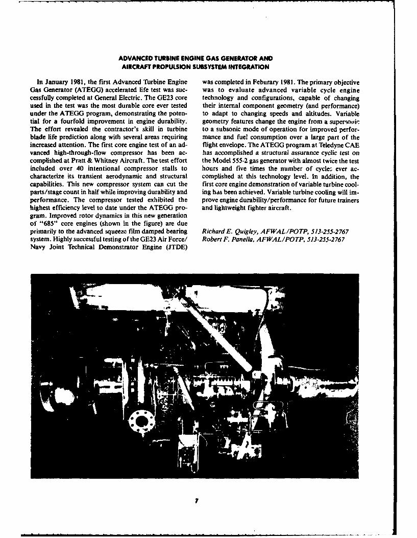
ADVANCED TURBINE ENGINE GAS GENERATOR ANDAIRCRAFT PROPULSION SUBSYSTEM INTEGRATION
In January 1981, the first Advanced Turbine Engine was completed in Feburary 1981. The primary objectiveGas Generator (ATEGG) accelerated life test was suc- was to evaluate advanced variable cycle enginecessfully completed at General Electric. The GE23 core technology and configurations, capable of changingused in the test was the most durable core ever tested their internal component geometry (and performance)under the ATEGG program, demonstrating the poten- to adapt to changing speeds and altitudes. Variabletial for a fourfold improvement in engine durability, geometry features change the engine from a supereonlicThe effort revealed the contractor's skill in turbine to a subsonic mode of operation for improved perfor-blade life prediction along with several areas requiring mance and fuel consumption over a large part of theincreased attention. The first core engine test of an ad- flight envelope. The ATEGG program at Teledyne CAEvanced high-through-flow compressor has been ac- has accomplished a structural assurance cyclic test oncomplished at Pratt & Whitney Aircraft. The test effort the Model 555-2 gas generator with almost twice the testincluded over 40 intentional compressor stalls to hours and five times the number of cycles ever ac-characterize its transient aerodynamic and structural complished at this technology level. In addition, thecapabilities. This new compressor system can cut the first core engine demonstration of variable turbine cool-parts/stage count in half while improving durability and ing has been achieved. Variable turbine cooling will im-performance. The compressor tested exhibited the prove engine durability/performance for future trainershighest efficiency level to date under the ATEGG pro- and lightweight fighter aircraft.gram. Improved rotor dynamics in this new generationof "685" core engines (shown in the figure) are dueprimarily to the advanced squeeze film damped bearing Richard E. Quigley, AFWAL/POTP, 513-255-2767system. Highly successful testing of the GE23 Air Force/ Robert F. Panella, AFWAL/POTP, 513-255-2767Navy Joint Technical Demonstrator Engine (JTDE)
7

HIGH POWER LEVELS FOR SPACE
Potential future space missions employing high power demonstrated thermal stability of the potted Nb1Sn coiljamming, space-based radars or directed energy also increases the probability of an early successful fast-weapons will require very high power levels. Two steps pulsed inductive energy storage and switching devicetoward providing such power have been taken recently fabricated entirely from Nb3Sn.with the demonstration of a superconducting coil and a In a second program, Power Electronics Associates,high power DC-DC converter. In the first of these ef- Incorporated, has developed and delivered a lightweightforts, General Electric, under Aero Propulsion 200-kilowatt inverter. The inverter converts relativelyLaboratory (APL) sponsorship, has achieved a low voltage (600 volts DC) to 25 kilovolts DC. Using atechnology breakthrough in superconducting coils for unique series-resonant concept, the inverter operates athigh-power generators. A brittle Nb3Sn superconduc- above 95%0 efficiency. High efficiency is critical for theting wire has been statically operated without degrada- use of this type of power by the use of lightweight, high-tion in a fully potted coil configuration that does not frequency transformers, which were also developedhave cooling slots. The coil was "ramped" to the super- through APL programs.conducting generator design field without degradation This specific power is three times better thanor training and was continuously ramped to 90% of the previously available inverters could provide. It makesmaximum current and back to zero for 134 cycles feasible the use of several proven low-voltage sourceswithout degradation or quenching. The figure shows a for the high-voltage requirements of space and airborne20 MW generator. missions.
The demonstrated capability equals or exceeds all cur-rent mission fast-start requirements anticipated formultimegawatt superconducting generators. The MajRichardD. Franklin, AFWAL/POOS, 513-255-6241
W
w0

HIGH PERFORMANCE AIRCRAFT AUXILIARY POWER UNIT
Endurance testing has been completed on a new high generator has been overdesigned and is actually in theperformance auxiliary power unit (APU) developed range of 75 to 90 KVA. The qualification test phase hasfor aircraft engine starting and checkout/standby. The been completed and eight additional systems will beextreme simplicity of the modular design in terms of fabricated to support a one-year service flight test pro-field maintenance was demonstrated along with 50 gram on two TAC A-10 aircraft.
, hours of test time. The unit had a power density of 185 Fuel pump failures on the F100 engine powering thehp/ft' and a specific fuel consumption of 0.62 to 0.65 F-16 aircraft have stimulated development of anlb/hp-hr. This Avco Lycoming LTS 101 derivative unit emergency backup pump system conceived andprovides a new APU alternative for aircraft power. demonstrated in-house to provide a "get-home"
General Electric under Aero Propulsion Laboratory capability. The system consists of a hydraulic motor(APL) contract has designed and fabricated a 60 KVA driving a standard fuel pump with an emergency throttl-
* permanent magnet variable speed constant frequency ing valve package. In the event of an engine main fuel(VSCF) generator system. The system provides high pump failure, a detector energizes the motor/pump,quality constant frequency electrical power directly which then supplies fuel flow to the engines. A contrac-from a variable speed source without the need for a tual and qualification program are being initiated to im-hydromechanical unit to drive the generator at a cons- plement the emergency system which promises to pro-tant speed. The use of permanent magnets results in vide a cost saving of 60 to 80 million dollars.
* very high energy density and eliminates the magneticstructure and windings required to produce a woundfield excitation. Flight qualification test of a generator Maj RichardD. Franklin, AFWAL/POOS, 513-255-6241(rotating) and a converter (static) revealed that the
4 9

ADVANCED SPACE POWER SYSTEMS
The success of Air Force satellite missions is critically pany under APL contract, has developed and1 dependent on a long life, reliable source of electrical demonstrated nickel-hydogen batteries offering 30%
power. Present satellite missions require solar array reduction in energy storage subsystem weight for Airareas up to 1200 feet2 to meet prime power requirements Force satellite missions. Specific performanceof 10 KW.. These requirements have been met in the capabilities provided are weight densities of 12 wattpast by silicon solar cell technology, however, Aero hours/pound in low earth orbit (LEO) and 16 wattPropulsion Laboratory (APL) through contract to hours/pound in geostationary orbit (GEO). This
A Hughes Aircraft Company has developed gallium technology has been demonstrated on a Space Divisionarsenide (GaAs) solar cells which offer more power, Special Projects Office Vehicle and nickel-hydrogenhigher efficiency, better radiation resistance, less volume, batteries have been selected as the primary power systemand the potential of less weight than silicon solar cells, on the Air Force Satellite Data System Program. ThisGaAs cells have demonstrated efficiencies of 17% at technical achievement of energy storage weight reduc-beginning-of-mission life and 14% at end-of-mission tion offers increased power or increased satellitelife. The technology has been demonstrated as feasible payload capability for future space systems. Extensionon the NTS-2 spacecraft and GaAs panels will be of satellite missions beyond five years in LEO and tensubstituted for two of the 28 silicon panels on the NASA years in GEO is now completely feasible as compared tolaunched Italian satellite San Marco D/L to be launched current mission lifetimes of 3 and 5-7 yeas, respective-in mid 1982. A three-year GaAs Manufacturing ly.Technology Program by the Materials Laboratory is be-ing undertaken to meet the need for an increased pro-duction capability by the mid 1980's. Dr. Robert R. Barthelemy, AFWAL/POOC,
During the past several years, Hughes Aircraft Com- 513-255-6235
W 10

ADVANUM tITAVOWE M~ DITCTM SYSTM
Detection is the first, and probably the single most gramming the microprocessor with an automatic self-important factor in the control of aircraft engine fires, check and verify feature, the false fire warnings ap-Current detection technology involves the direct ex- proach 0% and the confidence of detecting all fires ap-posure of a wire-like sensor to thermal energy and, proaches 100%. System response time is approximately
• therefore, must be located where the fire or overheat is one second and with the high level of reliability, i-Sexpected to occur. Several significant disadvantages in- mediate action can be taken to control a fire. If the
elude a high frequency of false alarms estimated as high system fails, a cockpit warning indicates that the systemas 60%, a failure to detect fires in 33% of actual fire in- is incapable of detecting a fire. A memory storagecidents, a slow detection and verification response enables maintenance personnel to identify the specificwhich could allow a fire to propagate beyond control, failed components.and a high level of maintenance damage. This UV fire detection system was installed in each
To overcome these deficiencies, Aero Propulsion engine bay of an FR-I I aircraft and successfully flightLaboratory (APL) aid Aeronautical System Division tested for nine months with 35 flight hours and 350(ASD), under a contract with General Dynamics, operational hours. Since the capabilities of theGraviner, Ltd., and HTL Industries, have developed microprocessor are highly versatile, the UV fire detec-and demonstrated a new radiation-sensitive fire detector tion system can be integrated with the conventionalsystem. This system utilizes microprocessor technology overheat systems, thereby increasing the payoff of suchto achieve a high degree of flexibility and reliability, a system.which enables the system to detect ultraviolet (UV)radiation from flames and to ignore cosmic radiation,
* lightning, and other transient conditions. Also, by pro- Thomas A. Hogan, AFWAL/POSH, 513-255-4160
I I
• . - . .1

FUEL TEONNOLOGY
With rapidly rising petroleum costs coupled with for ALCM in April 1981. As compared to JP-9, whichdepletion of domestic crude oil and escalation of costly was previously used in the ALCM, JP-10 providesoil imports, potential sources of aviation turbine fuels equivalent missile range and payload, but is superior infrom shale oil, coal, and tar sands are required. Under terms of safety, ground handling, availability, and
- Aero Propulsion Laboratory (APL) contracts, three storage stability. The current cost of JP-10 is $16/gallon*' commercial oil refining frins (Sun Oil Company, as compared to SS0/ga°lon for JP-9.
Ashland Oil Company, and UOP Process Division) Through APL sponsored contracts and in-house pro-have developed satisfactory processing techniques for grams, major advances in gas chromatography, liquidrefining domestic shale into aviation turbine fuel and chromatography, and nuclear magnetic resonance in-other finished products. In each case, the processes strumentations have made it possible to analyze com-yielded aviation turbine fuels that meet and, in many plex mixtures such as aviation turbine fuels. Thesecases, exceed current military fuel specifications at prices techniques are being aplied to the detailedcomparable to fuels produced from petroleum crude oil. characterization of aviation fuels being used in alternate
Under APL sponsorship, Sun Oil Company has fuels research programs at APL.developed high energy fuels (higher energy content per
:i unit volume) for use in tactical and strategic missiles.*~ The latest fuel, JP-10, was adopted as the specified fuel Arthur V. Churchill, AFWAL/POP, 513-255-5106
"V
op1

TURBINE ENGINE BEARING TECHNOLOGY
In a program with Pratt and Whitney Aircraft Group, these capabilities, improved analyses are needed forpowder metallurgy manufacturing technology has been designing and predicting the performance of bearingsapplied successfully to the production of aircraft- operating at these high speeds. In a program with Prattquality engine ball bearings. A prototype powder- and Whitney Aircraft Group, a design system was suc-processed bearing steel, CRB-7 alloy, was evaluated in cessfully developed for cylindrical roller bearingsfull-scale bearing life testing and the results compared to operating at speeds up to three million DN. The successa predicted life for today's standard bearing material, of this system was demonstrated by the design of a pro-M-50. The bearing design selected was from a current totype roller bearing (shown in the figure) that suc-turbine engine (TF33) mainshaft application and 20 of cessfully completed a 60-hour rig evaluation test. Dur-these bearings were successfully fabricated to aircraft ing the test, DN was varied from 2.2 to 3.0 million, withquality standards with P/M CRB-7 material. Life a total of 30 hours at three million DN.results obtained were statistically equivalent to that for A new technique for monitoring wear of problemconventional M-50. Overall, these results are quite en- bearings has been developed by Pratt and Whitney Air-couraging considering the pioneering nature of this ef- craft Group, Government Products Division. Thisfort. Powder metallurgy technology offers the potential technique, to supplement the standard spectrometric oilfor longer bearing life, lower cost bearings, and reduced analysis program, uses low level radioactive tagging ofuse of strategic materials, the bearing and monitoring the Iron 55 in the oil.
It is generally conceded that bearing capabilities in ex-cess of three million DN (bearing bore in mm times rpm)
" will be required for advanced engines. In developing Ronald D. Dayton, AFWAL/POSL, 513-255-4347
13V

TACTICAL LIQUID FUEL RAMJET DEMONSTRATION
Aero Propulsion Laboratory (APL) has successfully burner. The resulting extended range ramijet was freejetcompleted the ground demonstration of a liquid-fueled demonstrated, and a scale model cold-flow engine wasramjet suitable for providing Phoenix missile range wind tunnel integrated with a model of a Sparrow-sizecapability in a Sparrow-size missile. The engine design missile.and testing was performed by The Marquardt Com- Missile performance, based upon the test results, waspany, the prime contractor for the program. calculated to be superior to Phoenix at extended range.McDonnell-Douglas Corporation, as subcontractor, The high Mach number, high altitude range objectivewas responsible for the vehicle design and vehicle- was met, as well as lower priority objectives.propulsion integration activities. The Air Force program is complete and the
Existing strategic ramjet liquid fuel controls were technology is ready for transition to advanced develop-simplified and scaled down to provide a compact, high ment and preparation for flight evaluation. The Navy isturndown ratio throttle. The inlet was basically a two- expected to exploit and further develop this technologydimensional design; however, lateral compression by to provide propulsion for their Advanced Intercept Air-the side walls was a unique feature. Also, a two- to-Air Missile.dimensional precompression shroud, positioned im-mediately ahead of the inlet, improved high angle of at-tack capability. The inlet and fuel control were in- George E. Thompson, AFWAL, PORA, 513-255-5451tegrated with an ablatively lined stainless steel ram-
IF
14
A AliIIIa Ihlmm~l nI~unutma m a. d. l * .---

ASALM PROPULSION TECHNOLOGY
A significant Aero Propulsion Laboratory (APL) after the Aeronautical Systems Division (ASD) counter-technical effort in missile propulsion has been directed SUAWACS study is completed and futher direction is
- toward the design of a complete integral rocket/ramjet given.propulsion system satisfying the propulsion re- The Laboratory also provided technical support of anquirements of the Advanced Strategic Air-Launched ASD managed flight test program on the integralMissile (ASALM), and the demonstration of propulsion rocket/ramijet. In the flight tests, the maturity of in-system performance at representative ASALM trajec- tegral rocket/ramjet propulsion systems wastory conditions through a series of engine-component demonstrated for an ASALM missile. The technologyand freejet tests. The technical approach has been the developed is available for such weapon systems as an
* design of an integral rocket/ramjet engine and testing of SRAM replacement having twice the low altitude rangethe component designs through direct connect engine plus the capability of low level launch, high altitudetests. The best configuration was then freejet tested to cruise, followed by a low level run-in. This ASALMascertain integrated system performance. Two com- technology is also applicable to a counter-SUAWACSpetitive designs were evaluated under separate con- missile or a multi-mission strategic missile having bothtracts. The Chemical Systems Division's design is air-to-air and air-to-ground capabilities. In addition toresponsive to the McDonnell missile airframe configura- providing for an extended range SRAM size missile, thetion while The Marquardt Company's design is respon- technology can also be used to provide a greater numbersive to the Martin-Marietta configuration. The technical of missiles (up to two for one) in the same SRAMeffort on both contracts has been completed and both volume and still exceed the current SRAM flight range.
- designs have successfully demonstrated performanceover the whole flight envelope. The technologydeveloped under these contracts will be available for use George F. Thompson, AFWAL, PORA, 513-255-5451
U1W
A4
*
L

AIRCRAFT TURBINE ENGINE LUBRICATION
Following a number of seal failures in the TF34 mance oil on board the F-106. In the near future,engine on A-10 aircraft, Aero Propulsion Laboratory COBRA will be used to monitor the J75 operating with(APL) scientists have found that incipient failure can be routine oils, as well as engines on the C-141 and C-130reliably pinpointed by means of the Complete Oil aircraft.Breakdown Rate Analyzer (COBRA) instrument. This Engine designers rely on design guides for thedevice is extremely simple and economical to operate, development of high-speed turbomachinery, and forrequiring less than one minute and no special equipment predicting rotor-bearing critical speeds, unbalanceor personnel training. To date, COBRA has given 24 response, and rotor stability margin. The previouspositive indications of impending seal failure in the Design Guide Series, published in the 1960s, has beenTF34 engine. In each case, teardown of the engine has extremely valuable in this regard, but parts have becomeshown that a failure was imminent and that the COBRA nearly obsolete because of subsequent rapidprediction was correct. The routine maintenance pro- technological developments. To bridge this gap, a nine-cedure for checking the seal condition on the TF34 re- volume compilation, "Rotor-Bearing Dynamicsquires eight man-hours, and does not always give an ac- Technology Design Guide Series", has been prepared.curate indication of sump seal condition. Furthermore, Topics covered in the series range from flexible rotorseal failure typically happens suddenly and the normal dynamics to high-speed tapered roller bearings and foil-100-hour inspection cycle is therefore inadequate to type gas bearings, along with design information foridentify this type of failure. Near-continuous COBRA ball bearings, roller bearings, and fluid film bearings.monitoring, on the other hand, has already been shownto be both adequate and reliable. COBRA is now beingfield tested with the J75 engine using a new high perfor- Howard F. Jones, AFWAL/POSL, 513-255-4939
TF34 ENGINEFAILURE
COBRA
* READING
1180 1200 1220 1240ENGINE HOURS
,16

SECTION 11"VIONIC LABORATORY
17

GLOBAL POSITIONING SYSTEM NULL STEERING ANTENNA
The Null Steering Antenna (NSA) developed for the tive array having excellent satellite coverage,Global Positioning System (GPS) has been a major signal fidelity, and navigation accuracy in bothhighly successful AFWAL Avionics Laboratory effort. ECM and non-ECM environments.The NSA was developed to provide high anti-jam Avionics Laboratory development of the GPS Nulltechnology capability necessary for GPS user equipment Steering Antenna represents a significant achievementto continue to function fully in intensive hostile elec- for the Air Force. The NSA will play a major role intromagnetic environments. The antenna system was permitting high-performance tactical, cargo, anddesigned primarily for application on high performance strategic aircraft and other users to navigate with thetactical aircraft and has undergone extensive laboratory GPS system while operating in intense jamming en-and flight tests against multiple jamming sources with vironments. The NSA's unsurpassed anti-jamoutstanding performance results. capabilities are designed to allow Air Force vehicles hav-
The achievement objectives of the NSA program in- ing GPS receivers to obtain maximum position andelude the development of an adaptive array antenna velocity accuracy in an intense ECM environment andwhose performance, size, and cost characteristics met to provide highly accurate weapon delivery or cargothe need of GPS equipped high-performance aircraft. drop capability. NSA technology has been transferredThe technology advancements achieved and to the GPS Joint Program Office as a major risk reduc-demonstrated in the laboratory and flight test program tion for their Phase lib User Equipment Full Scale
* are: Engineering Development Programs. In summary, theFirst null steering adaptive array antenna to successful completion of the NSA program and
demonstrate anti-jam protection against multi- development of the first-generation F-16 conformalpie jammers with diverse modulations while antenna array has proven that NSA concepts willreceiving satellite GPS signals. significantly enhance the mission effectiveness of the
Development of a small (10" x 10") array Global Positioning System in intense jamming en-applicable to F-16 aircraft. Development of vironments.real-time adaptive antenna algorithms in-cluding pattern search techniques.
. Initial flight operation of a Null Steer adap- James E. Jones, AFWAL/AAAN-2, 513-255-5668
is"
V
..
W
ADVANCED MISSILE LAUNCH ENVELOPE ALGORITHM DEVELOPMENT
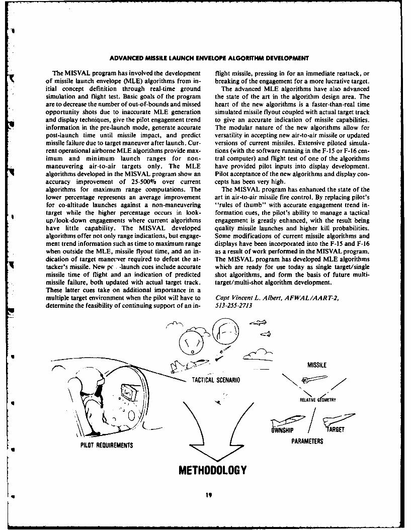
The MISVAL program has involved the development flight missile, pressing in for an immediate reattack, orof missile launch envelope (MLE) algorithms from in- breaking of the engagement for a more lucrative target.itial concept definition through real-time ground The advanced MLE algorithms have also advancedsimulation and flight test. Basic goals of the program the state of the art in the algorithm design area. Theare to decrease the number of out-of-bounds and missed heart of the new algorithms is a faster-than-real timeopportunity shots due to inaccurate MLE generation simulated missile flyout coupled with actual target trackand display techniques, give the pilot engagement trend to give an accurate indication of missile capabilities.information in the pre-launch mode, generate accurate The modular nature of the new algorithms allow forpost-launch time until missile impact, and predict versatility in accepting new air-to-air missile or updatedmissile failure due to target maneuver after launch. Cur- versions of current missiles. Extensive piloted simula-rent operational airborne MLE algorithms provide max- tions (with the software running in the F-I5 or F-16 cen-imum and minimum launch ranges for non- tral computer) and flight test of one of the algorithmsmaneuvering air-to-air targets only. The MLE have provided pilot inputs into display development.algorithms developed in the MISVAL program show an Pilot acceptance of the new algorithms and display con-accuracy improvement of 25-500% over current cepts has been very high.algorithms for maximum range computations. The The MISVAL program has enhanced the state of thelower percentage represents an average improvement art in air-to-air missile fire control. By replacing pilot'sfor co-altitude launches against a non-maneuvering "rules of thumb" with accurate engagement trend in-target while the higher percentage occurs in look- formation cues, the pilot's ability to manage a tacticalup/look-down engagements where current algorithms engagement is greatly enhanced, with the result beinghave little capability. The MISVAL developed quality missile launches and higher kill probabilities.algorithms offer not only range indications, but engage- Some modifications of current missile algorithms andment trend information such as time to maximum range displays have been incorporated into the F-15 and F-16when outside the MLE, missile flyout time, and an in- as a result of work performed in the MISVAL program.dication of target maneuver required to defeat the at- The MISVAL program has developed MLE algorithmstacker's missile. New pc -launch cues include accurate which are ready for use today as single target/singlemissile time of flight and an indication of predicted shot algorithms, and form the basis of future multi-missile failure, both updated with actual target track. target/multi-shot algorithm development.These latter cues take on additional importance in amultiple target environment when the pilot will have to Capt Vincent L. Albert, AFWAL/AART-2,determine the feasibility of continuing support of an in- 513-255-2713
MISSILE
/ TACTICAL SCENARIO
q RELATIVE GKOMETRY
O PARAM ET R
PILOT REQUIREMENTS ARAMETERS
METHODOLOGY
q 19

CM-HARDENED ADVANCED OPTRONIC SEEKER
Under Avionics Laboratory sponsorship, Systems (d) closer to one bomb, one target philosophy of war-Research Laboratory has developed an advanced, fare, and most of all (e) extended lifetime effectivenessCM-hardened, laser seeker (CHAOS). CHAOS for existing arsenal ordnance.has demonstrated significant improvement in CM- Although the circuitry involved in CHAOS washardening the Pave Way II Laser Guided Bomb (LGB) designed specifically for Pave Way II, the basic CMin a plug-in package compatible with both the LGB and technique is applicable to other laser seekers. The newthe Low Level Laser Guided Bomb (LLLGB). CHAOS LLLGB effort, Laser Maverick, the Army's Hellfire, orincorporates a new coding scheme and CM resistant any 1.06 laser seeker that produces master triggers afterprocessing circuitry. Of particular interest, is the use of the video detector preamplifiers are candidates fora microprocessor to implement the coding techniques. CHAOS technology. The CHAOS digital circuitry canUsing a microprocessor increases the flexibility and be reduced substantially in size and cost by the use ofadaptability to counter future threats. The CHAOS custom made integrated circuits. The cost of havingmicroprocessor software control provides: (a) an in- CHAOS CM-hardening in a laser seeker is about thetelligent search and discrimination capability to find a same cost (in large quantities) as a standard laser seeker.target veiled by complex CM's, (b) an extremely effec-tive and uninterruptable guidance to target, (c) adap-tability to discriminate against CM threats of the future, Jan M. Servaites, AFWAL/AARI-), 513-255-5292
20
U 20

..........

IR ATMOSPHERIC TRANSMISSION MEASUREMENTS
The ability to understand and predict atmospheric adverse weather conditions. On 7 May 1981, the devicetransmission is fundamental to successful operational was successfully demonstrated for the first time in bothdeployment of IR weapon systems. The DOD plan for the 3-5 and 8-14 micrometer IR bands.atmospheric R&D, formulated by OUSDRE, has a The transmissometer has been operated over an 8 Kmtechnical goal to provide a capability by 1984 to path in clear weather and bad weather with excellentmeasure, model, and predict accurately the atmospheric results. A significant disagreement with LOWTRANtransmission effects on DOD sensor and communica- was found in the 4.4-5.3 micrometer region. The Airtion systems. Force Geophysics Laboratory has modified
The LOWTRAN computer model is most often used LOWTRAN to conform to the measurements. Most ofwhen predictions based on general atmospheric the work to validate LOWTRAN remains to be done.transmission conditions are needed. This model has The large problems in atmospheric transmission model-never been completely validated by experimental ing are: the effect of aerosols, the role of visibility inmeasurements taken over long horizontal paths and predicting IR transmission, and the relationship of stan-over the full IR spectrum (3 through 14 micrometers) of dard meterological observables to IR transmission. Ainterest to the Air Force. Test instrumentation has not comprehensive measurement program is currently underbeen available to make these measurements. The way in the Targeting Systems Characterization FacilityAvionics Laboratory tried to make the measure- aimed at providing data to resolve these questions. Thements but failed. Commercial transmissometers were broadband transmissometer atmospheric transmissionevaluated and found inadequate. No such instru- measurements are compared to LOWTRAN predic-ment was available, even as a one-of-a-kind device, in tions. Supporting atmospheric physics andacademia or the atmospheric research community. The meteorological data are provided by the Targetingneed for LOWTRAN model validation was clearly Systems Characterization Facility. The effort is totallyneeded. in-house and conducted by Air Force personnel.
The Laboratory undertook the in-house developmentof a broadband IR atmospheric transmissometerspecifically designed to validate LOWTRAN over the Maj Robert L. Johnson, AFWAL/AARI, 513-255-6144full electro-optical spectrum, over an 8 km path in
620 TOWER
MODEL INPUTS
LOWTMAN
METEOROLOGICAL AND PATH CALCULATED*l PROPERTY MEASUREMENTS TANCMIASED
'~. OPTICAL RECEIVERS-VISUAL AND INFRARED
SOURCE
TRANSMISSION (%) cz
CALCULATE TO DATA COMPUTER R I 0 ELECTRONICS
* COMPARE MODEM
22
U
PARATUNE TRANSMIT FILTER
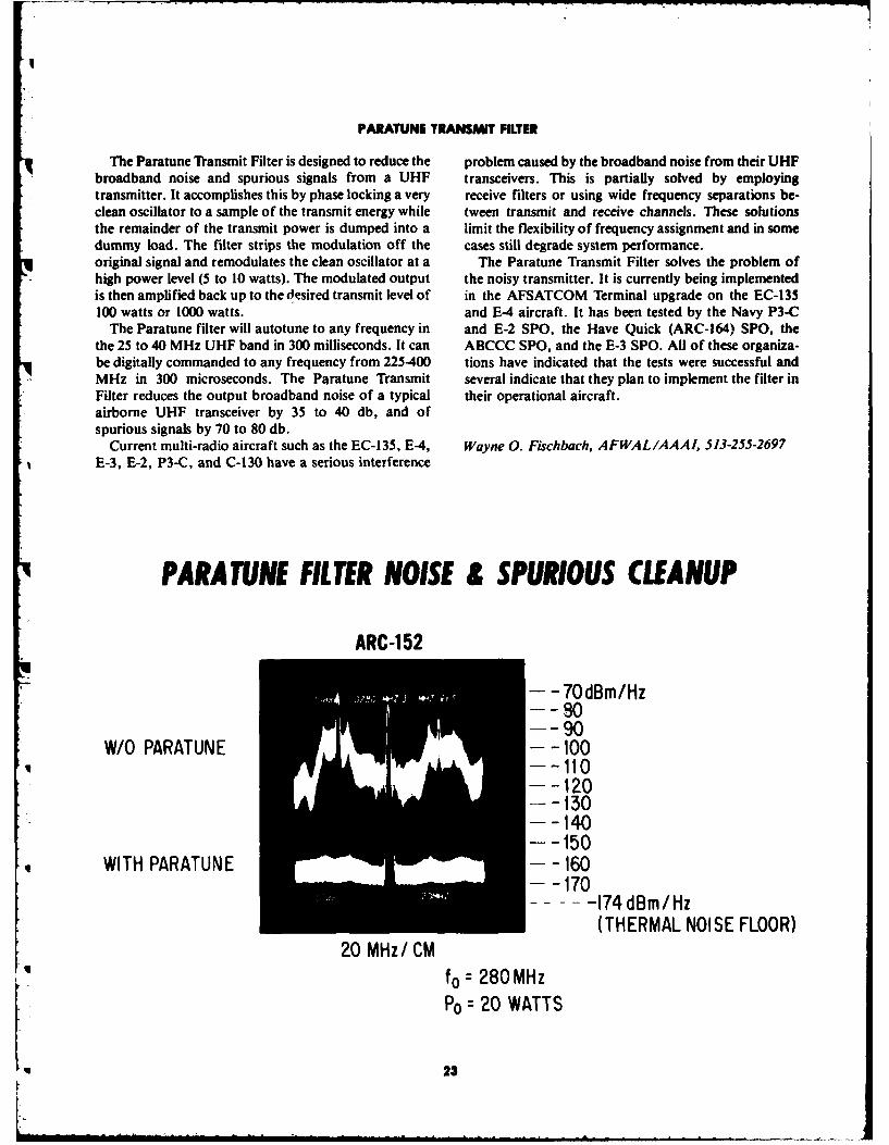
The Paratune fansmit Filter is designed to reduce the problem caused by the broadband noise from their UHFbroadband noise and spurious signals from a UHF transceivers. This is partially solved by employingtransmitter. It accomplishes this by phase locking a very receive filters or using wide frequency separations be-clean oscillator to a sample of the transmit energy while tween transmit and receive channels. These solutionsthe remainder of the transmit power is dumped into a limit the flexibility of frequency assignment and in somedummy load. The filter strips the modulation off the cases still degrade system performance.original signal and remodulates the clean oscillator at a The Paratune Transmit Filter solves the problem ofhigh power level (5 to 10 watts). The modulated output the noisy transmitter. It is currently being implementedis then amplified back up to the 6esired transmit level of in the AFSATCOM Terminal upgrade on the EC-135100 watts or 1000 watts. and E-4 aircraft. It has been tested by the Navy P3-C
The Paratune filter will autotune to any frequency in and E-2 SPO, the Have Quick (ARC-164) SPO, thethe 25 to 40 MHz UHF band in 300 milliseconds. It can ABCCC SPO, and the E-3 SPO. All of these organiza-be digitally commanded to any frequency from 225-400 tions have indicated that the tests were successful andMHz in 300 microseconds. The Paratune Transmit several indicate that they plan to implement the filter inFilter reduces the output broadband noise of a typical their operational aircraft.airborne UHF transceiver by 35 to 40 db, and ofspurious signals by 70 to 80 db.
Current multi-radio aircraft such as the EC-135, E-4, Wayne 0. Fischbach, AFWAL/AAAI, 513-255-2697E-3, E-2, P3-C, and C-130 have a serious interference
PARATUNE FILTER NOISE & SPURIOUS CLEANUP
ARC-152
- -70dBm/Hz-- 90
W/O PARATUNE -- 100--- 110-- 120- -130-- -140-- 150
WITH PARATUNE --- 160
.. .-- 174 dBm/Hz(THERMAL NOISE FLOOR)
20 MHz/ CMfo = 280 MHzPo = 20 WATTS
23

1RATWN EAM ACCELEOME
In 1980, the Avionics Laboratory started a quest This performance compares with and exceeds inertialto identify promising new ideas in unconventional grade (I nm/hr) accelerometers.sensors and examine their feasibility. As a result of this The accelerometer uses simple, low cost parts whichquest, Singer-Kearfott was awarded a one year contract are not critical and would be amenable to manufactur-to build and test a breadboard vibrating beam ac- ins methods analogous to the quartz watch industry.celerometer (VBA). The VBA test data have The vibrating beam accelerometer can impact the Airdemonstrated high accuracy performance and a poten- Force by providing inertial grade or high accuracy ac-tial for low cost production. The accelerometer makes celerometer at low cost, estimated at $200/axis. Presentuse of the vibrational properties of quartz beams which accelerometers of comparable performance costprovide a frequency shift proportional to acceleration. $3000/axis. The Air Force paid $100K for this bread-The device uses two quartz beams in a differential mode board contractual effort, but additional leverage wasto eliminate acceleration senstitive error effects of a achieved for the Air Force and DOD in that a number ofh single beam. The performance which has been achieved organizations have expressed interest in an applicationincludes the following: for the VBA.
Scale factor stability of 10 ugScale factor temperature sensitivity of 10 ppm/OFLong-term bias repeatability of 10 ug Richard W. Jacobs, AFWAL/AAAN-2, 513-255-5668
VACUM u rAN
.2 li (~l tO VF) EX RE
IIINrF
INPUT
AXIS
- AI INEIRTIAL -
AVASSISOLATOR MASS (I OF 2) "Z W MOL'NTIN(;
VIBRATING S'RFACEREAMTRANSI)UCFR(I OF 21
HIGH ACCURACY DUAL BEAM VBA CUTAWAY
DUALBEAM VBA-SCHEMATIC
*24

TACTICAL SBITATIC RADAR DEMONSTRATION
From 1978 to 1981, the Defense Advanced Re- phase by atomic references systems was demonstrated.search Projects Agency (DARPA) and the Avionics The two aircraft were flown in synchronous bistaticLaboratory sponsored the Tactical Bistatic Radar flight paths at preselected bistatic angles. The flightDemonstration (TBIRD) with Goodyear Aerospace paths were maintained through motion compensationCorporation, which showed that coherent bistatic radar using an inertial navigation system updated continuous-operation is feasible. During a rigorous flight test pro- ly by tracking ground reference points (beacons) andgram, TBIRD demonstrated for the first time a silent controlled by an onboard microcomputer.Synthetic Aperture Radar (SAR) imaging capability. By The successful demonstration of bistatic radar opera-using a standoff illuminator aircraft (60 km from the tion showed that it is possible for an airbornetarget) and a receiver aircraft flying toward the target, surveillance or combat aircraft to operate passively nearbistatic data were obtained of tactical military targets in the forward edge of the battle area, hence, reducing itsa desert background. Bistatic imagery was produced vulnerability to detection, location, and track.from these data using a contractor furnished program-mable polar processor. In addition to demonstrating thefeasibility of bistatic radar operation, synchronization Richard J. Koesel, AFWAL/AARM-1, 513-255-5771of the illuminator and the receiver aircraft in time and
I
.........................~~~. .. ..... ..i~ ii~ i i! i-i-:i::
- 'iiii~
.. .. I .......
25

ACOSTO-OPFTICAL RF SPECTRUM ANALYZERS
In tiscal year 1981, the Air Force received delivery of proof of feasibility of AO RF signal processing for spec-two different feasibility models of Acousto-Optical trum analysis. These devices did not meet the dynamic(AO) RF Spectrum Analyzers, which, when fully range and resolution requirements necessary for opera-developed, will lead to greatly improved ability to sort tional use and, therefore, need additional developmentand identify unknown radar signals. Two AO RF Spec- or advanced development work to achieve the desiredtrum Analyzers, one in a planar integrated optics con- performance characteristics and packaging for aircraftfiguration and one utilizing bulk optical components to environments.determine the extent to which miniaturization could beaccomplished were delivered. Both spectrum analyzersdemonstrated an ability to receive and process multiple L/CoI Gary K. Pritchard, AFWAL/AAD, 513-255-4998signals, both CW and pulse, thereby demonstrating
MINATURE ACOUSTO-OPTICAL INTEGRATED OPTICSSPECTRUM ANALYZER SPECTRUM ANALYZER
V
q 26
ALL ASPECT GUNSIGHT EVALUATION
oThe flight evaluation of the F-IS advanced gunsight design to implement system blending and provide pilothas been completed. The potential military significance utility in TAC simulation at Luke AFB. Simulation
* of this task is all aspect gunnery attack which should results demonstrated significant capability improvementresult in more firing opportunities, significantly higher over current operational lead computing sights. Subjectprobability of hit, and optimized mechanization for pilots unanimously recommended flight test evaluationother than rear quarter attack. The advanced gunsights of the complete blended system.should also be implemented at lower cost and give easypilot usage and training. This effort transitioned to PE63203F, Project 69DF, "Integrated Gunfire Control Lt. James E. Rittinghouse, AFWAL/AART-i,Technology." This FY81 program accomplished the 513-255-4794
S27L.

W
FIREFLY il
The IFFC-I/FIREFLY III Program is a joint thiness tests were flown from McDonnell's facilities ineffort between the Flight Dynamics and Avionics St. Louis, Missouri through April and May 1981. TheseLaboratories to demonstrate that integrating the flight successfuly demonstrated safe system operation, as weBand fire control systems will improve a fighter's sur- as low noise air-to-air tracking by the ATLIS 11 E-Ovivability and accuracy, and permit more versatile sensor/tracker pod which provides line of sight data tomaneuvers. The IFFC-i (Integrated Flight/Fire Con- the fire control system. Upon successful airworthinesstrol) contract to McDonnell Aircraft Company is for the certification, the IFFC-I/FIREFLY III system went todevelopment of the flight control system and overall in- the Air Force Flight Test Center, Edwards Air Forcetegration and is managed by AFWAL/FIGX. The Base, California, for a 15-month flight test effort. Air-FIREFLY Ill contract to General Electric Company is to-air and air-to-ground operation of the ATLIS 11 podfor the fire control system development and is managed and coupling of the flight control system have alreadyby AFWAL/AART. The current Lead Computing Op- been demonstrated successfully. The director gunnerytical Sight (LCOS) in most fighter aircraft is limited to a system and maneuvering attack system, developedcone about 400 to either side of tail of the target; the under Avionics Laboratory contract, have already beenFIREFLY I11 system expands this to 3600, or an all proven in numerous simulations and can stand alone,aspect weapon. In air-to-ground attack, current systems without coupling. The FIREFLY III system can beforce the pilot to fly wings level to achieve high ac- retrofitted to current fighter aircraft to allow maneuver-curacy, leaving him vulnerable to linear predictor air ing attack in air to ground. Design of the system is suchdefense. The FIREFLY Ill system allows a maneuvering that aircraft characteristics, weapon parameters, or sen-
* attack which greatly reduces vulnerability without com- sors can be varied with minimal software changes.promising accuracy.
Modification of the testbed F-15B aircraft was com-pleted in December 1980 with ground testing and soft- Lt. Henry F. Ziemba, AFWAL/AART-3, 513-255-5259ware testing continuing through March 1981. Airwor-
W 23
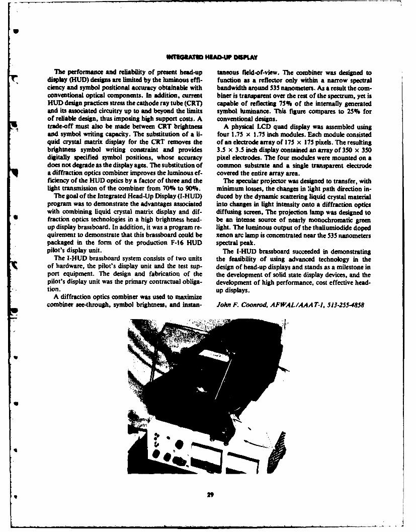
INTUGTW TW HUADAUP DOWtAY
The performance and reliability of present head-up taneous field-of-view. The combiner was designed todisplay (HUD) designs are limited by the luminous effi- function as a reflector only within a narrow spectralciency and symbol positional accuracy obtainable with bandwidth around 535 nanometers. As a result the com-conventional optical components. In addition, current biner is transparent over the rest of the spectrum, yet isHUD design practices stress the cathode ray tube (CRT) capable of reflecting 75% of the internally generatedand its associated circuitry up to and beyond the limits symbol luminance. This figure compares to 25% forof reliable design, thus imposing high support costs. A conventional designs.trade-off must also be made between CRT brightness A physical LCD quad display was assembled usingand symbol writing capacity. The substitution of a 1- four 1.75 x 1.75 inch modules. Each module consistedquid crystal matrix display for the CRT removes the of an electrode array of 175 x 175 pixels. The resultingbrightness symbol writing constraint and provides 3.5 x 3.5 inch display contained an array of 350 x 350digitally specified symbol positions, whose accuracy pixel electrodes. The four modules were mounted on adoes not degrade as the display ages. The substitution of common substrate and a single transparent electrodea diffraction optics combiner improves the luminous ef- covered the entire array area.ficiency of the HUD optics by a factor of three and the The specular projector was designed to transfer, withlight transmission of the combiner from 70% to 90%. minimum losses, the changes in ight path direction in-
The goal of the Integrated Head-Up Display (i-HUD) duced by the dynamic scattering liquid crystal materialprogram was to demonstrate the advantages associated into changes in light intensity onto a diffraction opticswith combining liquid crystal matrix display and dif- diffusing screen, The projection lamp was designed tofraction optics technologies in a high brightness head- be an intense source of nearly monochromatic greenup display brassboard. In addition, it was a program re- light. The luminous output of the thaliumiodide dopedquirement to demonstrate that this brassboard could be xenon arc lamp is concentrated near the 535 nanometerspackaged in the form of the production F-16 HUD spectral peak.pilot's display unit. The I-HUD brassboard succeeded in demonstrating
The I-HUD brassboard system consists of two units the feasibility of using advanced technology in theof hardware, the pilot's display unit and the test sup- design of head-up displays and stands as a milestone inport equipment. The design and fabrication of the the development of solid state display devices, and thepilot's display unit was the primary contractual obliga- development of high performance, cost effective head-tion. up displays.
A diffraction optics combiner was used to maximizecombiner see-through, symbol brightness, and instan- John F. Coonrov, AFWAL/4AA T-1, 513-255-4858
U
•2
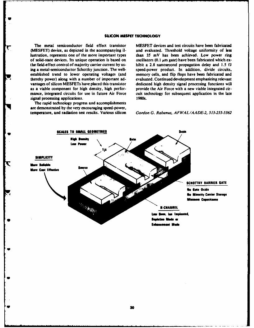
SILICON MESMET TECHNOLOGY
The metal semiconductor field effect transistor MESFET devices and test circuits have been fabricated(MESFET) device, as depicted in the accompanying il- and evaluated. Threshold voltage uniformity of lesslustration, represents one of the more important types than 35 mV has been achieved. Low power ringof solid-state devices. Its unique operation is based on oscillators (0.1 lAm gate) have been fabricated which ex-the field-effect control of majority carrier current by us- hibit a 2.8 nanosecond propagation delay and 1.5 fJing a metal-semiconductor Schottky junction. The well- speed-power product. In addition, divide circuits,established trend to lower operating voltages (and memory cells, and flip flops have been fabricated andthereby power) along with a number of important ad- evaluated. Continued development emphasizing relevantvantages of silicon MESFETs have placed this transistor dedicated high density signal processing functions willas a viable component for high density, high perfor- provide the Air Force with a new viable integrated cir-mance, integrated circuits for use in future Air Force cuit technology for subsequent application in the latesignal processing applications. 1980s.
The rapid technology progress and accomplishmentsare demonstrated by the very encouraging speed-power,temperature, and radiation test results. Various silicon Gordon G. Rabanus, AFWAL/AADE-2, 513-255-5362
SCALES TO SUALL SEOlETPIES DaN
SIMPUCITY
MUwe Cest Efoative
SCHOTTKY BARRIER GATE
No Mmioty Cams StmopAio CanpW"Me
II-CNANNlEL
Low Oim. I= Imlanted.
Sepletim Med aEnmmmemN Mode
i30
_ _ , . .- u 1 . t . . . . -
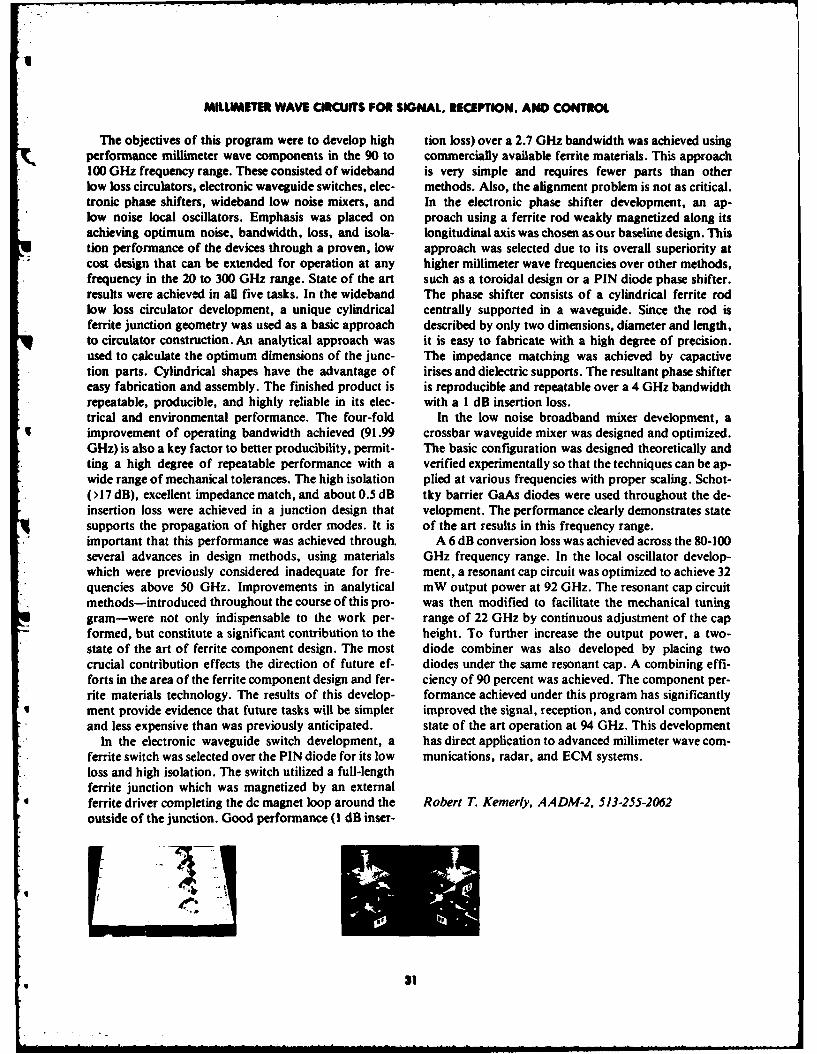
MILLIMETR WAVE CIRCUITS FOR SIGNAL. RECEPTION, AND CONTROL
The objectives of this program were to develop high tion loss) over a 2.7 GHz bandwidth was achieved usingperformance millimeter wave components in the 90 to commercially available ferrite materials. This approach100 GHz frequency range. These consisted of wideband is very simple and requires fewer parts than otherlow loss circulators, electronic waveguide switches, elec- methods. Also, the alignment problem is not as critical.tronic phase shifters, wideband low noise mixers, and In the electronic phase shifter development, an ap-low noise local oscillators. Emphasis was placed on proach using a ferrite rod weakly magnetized along itsachieving optimum noise, bandwidth, loss, and isola- longitudinal axis was chosen as our baseline design. Thistion performance of the devices through a proven, low approach was selected due to its overall superiority atcost design that can be extended for operation at any higher millimeter wave frequencies over other methods,frequency in the 20 to 300 GHz range. State of the art such as a toroidal design or a PIN diode phase shifter.results were achieved in all five tasks. In the wideband The phase shifter consists of a cylindrical ferrite rodlow loss circulator development, a unique cylindrical centrally supported in a waveguide. Since the rod isferrite junction geometry was used as a basic approach described by only two dimensions, diameter and length,to circulator construction. An analytical approach was it is easy to fabricate with a high degree of precision.used to calculate the optimum dimensions of the junc- The impedance matching was achieved by capactivetion parts. Cylindrical shapes have the advantage of irises and dielectric supports. The resultant phase shiftereasy fabrication and assembly. The finished product is is reproducible and repeatable over a 4 GHz bandwidthrepeatable, producible, and highly reliable in its elec- with a I dB insertion loss.trical and environmental performance. The four-fold In the low noise broadband mixer development, aimprovement of operating bandwidth achieved (91.99 crossbar waveguide mixer was designed and optimized.GHz) is also a key factor to better producibility, permit- The basic configuration was designed theoretically andting a high degree of repeatable performance with a verified experimentally so that the techniques can be ap-wide range of mechanical tolerances. The high isolation plied at various frequencies with proper scaling. Schot-(>17 dB), excellent impedance match, and about 0.5 dB tky barrier GaAs diodes were used throughout the de-insertion loss were achieved in a junction design that velopment. The performance clearly demonstrates statesupports the propagation of higher order modes. It is of the art results in this frequency range.important that this performance was achieved through. A 6 dB conversion loss was achieved across the 80-100several advances in design methods, using materials GHz frequency range. In the local oscillator develop-which were previously considered inadequate for fre- ment, a resonant cap circuit was optimized to achieve 32quencies above 50 GHz. Improvements in analytical mW output power at 92 GHz. The resonant cap circuitmethods-introduced throughout the course of this pro- was then modified to facilitate the mechanical tuninggram-were not only indispensable to the work per- range of 22 GHz by continuous adjustment of the capformed, but constitute a significant contribution to the height. To further increase the output power, a two-state of the art of ferrite component design. The most diode combiner was also developed by placing twocrucial contribution effects the direction of future ef- diodes under the same resonant cap. A combining effi-forts in the area of the ferrite component design and fer- ciency of 90 percent was achieved. The component per-rite materials technology. The results of this develop- formance achieved under this program has significantlyment provide evidence that future tasks will be simpler improved the signal, reception, and control componentand less expensive than was previously anticipated. state of the art operation at 94 GHz. This development
In the electronic waveguide switch development, a has direct application to advanced millimeter wave com-ferrite switch was selected over the PIN diode for its low munications, radar, and ECM systems.loss and high isolation. The switch utilized a full-lengthferrite junction which was magnetized by an externalferrite driver completing the dc magnet loop around the Robert T. Kemerly, AADM-2, 513-255-2062outside of the junction. Good performance (I dB inser-
31
w
DUAL MODE RECOGNIZER PROGRAM SUMMARY
Current Air Force air superiority fighters are equip- tion. The performance goals for percent of correct iden-ped with long-range all-weather radars and medium tification, range of identification, and false alarm raterange missiles. Operational tactics in today's air battle were all met or exceeded. Transition of the algorithmsare limited however by the need for positive, high con- to the Aeronautical Systems Division has been made.fidence identification of friend and foes. Current These algorithms, when implemented as a processingtechniques available in fighters are limited to mode in future radars, will provide the Air Force with acooperative IFF response and/or identification by significant all-weather, day/night target identification
, visual aided sensors. capabiility. While the DMR algorithm may initiallyTo satisfy the need for an all-weather, high stand alone, providing a real capability in time for the
confidence identification, the Avionics Laboratory Advanced Medium Range Air-to-Air Missilehas successfully completed the development of (AMRAAM) introduction, it also has good potential forthe Dual Mode Recognizer (DMR), an algorithm integration with identification inputs from other sensorswhich performs feature extraction within the signal pro- within the context of an overall IFFN fusion algorithm.cessing of the on-board radar. Following years ofalgorithm development and collection of an airbornedata base, the Laboratory demonstrated the ability of Marvin Spector, AFWAL/AART, 513-255-5144the algorithm to provide highly reliable target identifica-
S32

SECTION III
FLIGHT DYNAMICS LABORATORY

F-4 STRUCTURAL LIFE EXTENSION
The F-4 airframe was designed two decades ago for a At prescheduled intervals during the fatigue test pro-F service life of 4,000 flight hours. Presently, the F-4C/D gram, structural modifications were made to the test air-
fleet is nearing the end of its design service life and is craft which were the same as those modifications madeslated to continue in operational service. To double to F-4 service aircraft at the same number of flightthe structural life of the F-4C/D aircraft, the Flight hours. Included were modifications to the pylon hole,Dynamics Laboratory recently completed the most wing fold rib, main spar fasteners, and fuel cell. A ma-comprehensive airframe fatigue test ever conducted jor achievement of the test program was the physicalby the Air Force. proof that the modified structure indeed provided the
Prior to the test setup, a damage tolerance and life required airframe structural life extension.assessment study was conducted. Load conditions About 4,000 F-4 aircraft are currently in operationalshown to be significant to the fatigue life of the struc- service by the USAF and allied nations. The fatigue testture were simulated in the test. The distinct load program proved the adequacy of the structuraldistributions associated with 144 different points in the modifications made to the F.4 airframe, determined ad-F-4 flight envelope were imposed. The test provided an ditional modifications required, and provided informa-automated comparison of strain measurements with tion on the appropriate scheduling of these modifica-prediction, as well as the capability to recall and print tions for the entire F-4 fleet. An estimated $I.5M wasout data at all times in case of a catastrophic failure of saved by conducting the fatigue test program in-house.the structure. Four independent levels of automatic pro-tection were functional during the entire progress of the
U test program, making it the most failsafe system yet Robert L. Schneider, AFWAL/FIBT, 513-255-5059devised in the testing industry. Sanford Lustig, AFWAL/FIBT, 513-255-5059
UU
V.
a 34

COMPOSITE DEPLOYMENT MODULE
ring the MX missile development program, the The composite deployment module had an actualinum baseline deployment module (DM) for the weight savings of over 40 pounds and an estimated costdid not meet system structural requirements. savings up to 100 per unit compared to the aluminum
:eep the program on track, the Flight Dynamics design. This significant weight reduction offers poten-)ratory developed a full-scale composite DM tial missile benefits in terms of increased fuel capacity orI on the MX configuration and requirements. payload, resulting in additional range or target foot-,ing graphite/epoxy, a detail design was developed print for the MX. A substantial reduction in assemblyhe interior structure of the deployment module, re- cost was achieved with the composite DM through ang the baseline aluminum outer shell. The design reduction in part count by two orders of magnitude.ill static and dynamic loading conditions, as well as Recently, the composite deployment module wasrical and nuclear environments. A full-scale com- selected as the new baseline for the MX missile system.nt was fabricated including all reentry vehicle The composite DM was instrumental in preventing themounting fixtures. A dynamic test was conducted need to slip the MX development schedule to redesign
he unit with a full complement of realistic RV the original aluminum baseline deployment module.lators to determine critical data on deflection andral frequency. In all test conditions, the compositeexceeded MX requirements and was within 10-15% Capt Barry A. Eller, AFWAL/FIBA, 513-255-5006•edicted values.
5

SUPERPLASTIC FORMED ALUMINUM STRUCTURE
The increasing technical complexity and per- ent ever produced, a T-39 forward fuselage frame, wasformance of military aircraft reveal a need to reduce fabricated and evaluated under this Laboratory pro-the cost and weight of aircraft structure. The Flight gram. The SPF design had 5 detail parts and 20Dynamics Laboratory has demonstrated that fasteners, compared to 18 detail parts and 187 fasteners
* superplastic forming (SPF) of high strength aluminum for the baseline component. The SPF part resulted in aalloys is a significant breakthrough in producing unique 35% cost savings and a 22% weight savings.structural configurations not possible with current SPF aluminum can provide significant payoffs to cur-aluminum forming processes. rent and future Air Force systems. A recent Laboratory
SPF aluminum is a technology that allows the form- study has shown that 22% of all structural aluminum ining of one piece wing and fuselage structural elements a 500,000 lb transport, such as CX, could be replaced bywith integral flanges and stiffeners from thick gage, SPF aluminum components. This would result in say-high strength, aluminum sheet stock. SPF aluminum ings as high as $600 million in life cycle costs and 100parts replace built-up components that employ labor in- million gallons of fuel for a 100 aircraft fleet.tensive, mechanically fastened subassemblies or exten-sive machining operations.
The only full-scale SPF aluminum airframe compon- James Tss, AFWAL/FIBC, 513-255-2582
GU As 3670
• 36
INTEGML FUEL TANK TEST METHODS AND CETERIA
Although the repair of fuel leaks in aircraft fuel tanks tegral fuel tanks independently. It utilizes computer-has been one of the highest maintenance cost items dur- controlled fatigue and static loading under various en-ing the service life of DOD aircraft, fuel containment vironmental conditions of temperature ( -65 * to 275 °F)has been a secondary consideration to structural integri- and internal pressure, with and without JP-4 fuel. A
• ty, durability, and survivability, complete data acquisition system is also available.Previous testing for fuel containment has proven to The facility is currently being used for comparison
be inadequate because it could not uncover design defi- tests of various sealing concepts of integral fuel tanks.ciencies that result in fuel leakage. It was determined To date, eight sealant concepts have been tested utilizingthat fuel containment can be affected by basic structural F-16 type integral fuel tanks. The results of this testingdesign and fabrication, sealing materials and methods, are being used to develop design criteria and
- and the environmental conditions to which aircraft are methodology to improve the in-service life of future in-exposed. tegral fuel tanks.
Therefore, to test integral fuel tanks, an in-house facility was designed and constructed by theFlight Dynamics Laboratory. This in-house facility, a Martin D. Richardson, AFWAL/FIBT, 513-255-2291first in this country, has the capability of testing two in-
3
* .7

U
A-7D COMPOSITE OUTER WING PANEL TEST PROGRAM
The A-7D Composite Outer Wing Panel Test itiated to certify the composite outer wings for the entireProgram was a follow-on effort to a Materials La- life (8000 hours) of the A-7 aircraft. This programboratory program concerning advanced composite would provide additional flying experience and con-primary wing structures. The first phase consisted of fidence in the potential for the use of compositesselection of materials and development of the manufac- as primary structures. The Flight Dynamics Labor-turing processes, tooling, and production controls. atory was to continue the fatigue test programPhase I1 included laboratory static and fatigue tests by in-house utilizing its Structures Test Facility. Thethe contractor, LTV, and installation and service track- Materials Laboratory would continue its service track-ing of eight composite outer wings on Air National ing and field inspection program. One of the flying ar-Guard A-7 aircraft. ticles was removed for use as the fatigue test specimen.
During Phase 11, this graphite and boron-epoxy struc- The fatigue test was started in July 1980 and completedture was certified for 750 hours of flight. As the coin- in March 1981.posite outer wings reached 750 hours of flight, it was The A-7 composite outer wing panel successfullyproposed to remove them from the aircraft. Since these substained 16,000 simulated flight hours with no struc-composite outer wings were the only composite primary tural failures. Therefore, the composite primary struc-structures on Air Force aircraft, a study was made to ture is adequate for a lifetime of 8,000 flight hours.determine what additional efforts might be accomplish-ed to gain futher benefits from the program. Itwas decided that a joint Flight Dynamics Labor- Murray N. England, AFWAL/FIBT, 513-255-2291atory/Materials Laboratory program would be in- Frank L. Fechek, Jr., AFWAL/MLSS, 513-255-3370
4
--W 36

F-lLA LAMINATED CANOPY
Flight safety hazards that have recently received in- alternate production options, while saving $8 million increased awareness include the aircraft birdstrike prob- acquisition costs for the balance of the F-16 aircraftlem and the potentially serious coating loss problems production program. Since the laminated canopy con-due to erosion and pitting. To combat these prob- figurations are expected to be in service twice as long aslems, the Flight Dynamics Laboratory has developed the current production canopy, fewer canopyand safety of flight qualified a new crew station changeouts and less overall maintenance should be re-cockpit transparency for the i-16 aircraft. quired throughout the F-16 fleet. As a result, an addi-
The new laminated plastic transparency system pro- tional life cycle cost savings of $175 million is projectedvides 350 knot, four pound birdstrike protection and for the total 1,388 USAF F-16 aircraft buy.multi-year service life. Two versions of this design were The improved characteristics of the new laminatedselected by the F-16 System Program Office for use on canopy design has enabled the USAF to negotiate, forproduction F-16 aircraft, and will be provided as the first time, a minimum four year service warrantygovernment furnished equipment to the F-16 contrac- period. Under the warranty, defective canopies will betor. replaced at no increase in cost to the government.
The Laboratory's alternate canopy program for theF-16 resulter. in three qualified sources for fabricationof F-16 laminated canopies. By using multiple sources, Richard L. Peterson, AFWAL/FIEA, 513-255-6524the Air Force enhanced competition and provided for
3
: ' 3,

COMBINED ENVIRONMENTS RELIABILITY TESTING
Once deployed, the performance and reliability of CERT program showed a much improved correlationavionics systems are generally much lower than with actual field failure data over that achievable withspecified by the procuring activities and desired by the other currently used methods. The CERT testusing commands. This frequently occurs because the methodology can be used to accurately predict, in aavionics systems are subjected to unrealistic en- laboratory environment, the failure rates and modesvironmental test conditions prior to deployment in the that equipment would experience when actuallyfield. operating in the field. Thus, the CERT concept can be
The Flight Dynamics Laboratory recently com- used to determine the accuracy of a contractor's equip-pleted a technology program that promises to have ment life design predictions under realistic environmen-a far reaching impact on the acquisition of aeronautical tal test conditions.equipment for future weapon systems. The program in- As part of the CERT development and evaluationvolved the development, implementation, and verifica- program, the Laboratory completely revised the stan-tion of a significant new test methodology called Com- dard DOD dynamic testing methods to be more
" bined Environments Reliability Testing (CERT). CERT realistic, tailorable, and cost effective. These revisedessentially combines several critical parameters testing methods, when combined with the CERT(temperature, vibration, altitude, and humidity) into a technology, should contribute significantly to thesingle test. Each parameter profile is determined deployment of more cost effective and reliable equip-analytically or selected on the basis of previous flight ment systems.test data. In this way, the CERT facility actually "flies"the equipment being tested through a selected missionprofile using all test parameters simultaneously. Dr. Alan H. Burkhard, AFWAL/FIEE, 513-255-6078
Test results from the two-year validation phase of the
~CERTm
• COMBINED ENVIRONMENT RELIABILITY TEST
~MISSION PROFILE TESTREALISM At ,,, a
FLY EQUIPMENT IN LABORATORY -_"
,Uw4f
1P 40
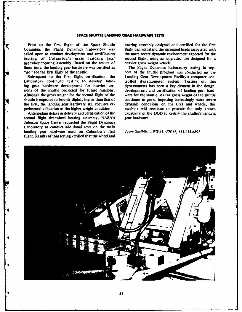
SPACE SHUTTLE LANDING GEAR HARDWARE TESTS
Prior to the first flight of the Space Shuttle bearing assembly designed and certified for the firstColumbia, the Flight Dynamics Laboratory was flight can withstand the increased loads associated withcalled upon to conduct development and certification the more severe dynamic environment expected for thetesting of Columbia's main landing gear second flight, using an upgraded tire designed for atire/wheel/bearing assembly. Based on the results of heavier gross weight vehicle.those tests, the landing gear hardware was certified as The Flight Dynamics Laboratory testing in sup-"go" for the first flight of the shuttle. port of the shuttle program was conducted on the
Subsequent to the first flight certification, the Landing Gear Development Facility's computer con-Laboratory continued testing to develop land- trolled dynamometer system. Testing on thising gear hardware development for heavier ver- dynamometer has been a key element in the design,sions of the shuttle projected for future missions. development, and certification of landing gear hard-Although the gross weight for the second flight of the ware for the shuttle. As the gross weight of the shuttleshuttle is expected to be only slightly higher than that of continues to grow, imposing increasingly more severethe first, the landing gear hardware still requires ex- dynamic conditions on the tires and wheels, thisperimental validation at the higher weight condition. machine will continue to provide the only known
Anticipating delays in delivery and certification of the capability in the DOD to certify the shuttle's landingsecond flight tire/wheel bearing assembly, NASA's gear hardware.Johnson Space Center requested the Flight DynamicsLaboratory to conduct additional tests on the mainlanding gear hardware used on Columbia's first Igors Skriblis, AFWAL/FIEM, 513-255-6891flight. Results of that testing verified that the wheel and
I4
II •
q AL

AIRCRAFT GROUND MOBILITY SYSTEM
For many years, the vulnerability of airfield were significantly below the F-16 landing gear designpavements during enemy hostilities has been a matter of limit loads. Both the nose and main landing gear mobili-continuing concern. As part of the solution to ty systems performed satisfactorily. Rut depths duringthis problem, the Flight Dynamics Laboratory de- tow testing over sod were approximately I to 1 inches.veloped an Aircraft Ground Mobility System (AGMS) The tow loads rarely exceeded 4,000 lbs, well below thefor the F-16 to provide the capability of moving design limit load of 9,257 lbs.aircraft over bomb damaged pavement or unstabilized, The AGMS is a temporary installment with a quickoff-runway soil surfaces. attachment/detachment scheme. It will provide the
The AGMS consists of wide, Hytrel polyester ability to move aircraft to survivable takeoff siteselastomer track segments which are assembled together following an attack on the airfield, greatly enhancingand strapped around the aircraft tire. The AGMS the post attack effectiveness of aircraft such as the F-16redistributes the aircraft tire load over a larger ground or F-15. It will also allow the airfield commander thecontact area, reducing the over-ground bearing option of concentrating the rapid runway repair on thepressures by over 70 percent. Specifically, for the F-16 runways, instead of trying to repair both runways and
- application, nominal unit ground pressures were re- taxiways. The AGMS provides an additional advantageduced from 275 psi down to approximately 65 psi. of protecting aircraft tires from debris on battle dam-
The AGMS was tested in-house in the Laboratory's aged surfaces.Landing Gear Development Facility and on a GF-16 air-
• craft on taxiway and sod surfaces at Wright-PattersonAir Force Base. The loads experienced during these tests David J. Perez, AFWAL/FIEM, 513-257-2129
-
" m 42

DIGITAC OPTICAL FLIGHT CONTROLS
Future tactical aircraft will need reliable and combat MUX bus design emphasizes detection of functionalsurvivable systems to continue the aircraft's effec- failures and ensures failsafe operational capability bytiveness against the ever expanding threat. To meet electrically isolating failures.this challenge, the Flight Dynamics Laboratory has Fiber optic MUX busses are not bandwidth limited asdeveloped a dual redundant fiber optic multiplexed are electrical wire systems. These small, lightweight(MUX) data bus and successfully demonstrated it on a pairs of fiber optic cables can replace large bundles ofmodified YA-7D test aircraft. wires and be easily distributed within the aircraft for in-
Transmitting flight safety critical data optically, the creased survivability. Simulated lightning strike testsdual fiber optic MUX busses operate simultaneously conducted on the DIGITAC system have demonstratedunder software control programmed in DIGITAC's that fiber optic MUX busses provide excellent electricaldigital flight control computers. These computer units hazard protection.control the data being transferred over the fiber optic DIGITAC's dual redundant fiber optic MUX bussesMUX busses to and from remote terminals which inter- have operated flawlessly in over 52 test flights in the
* face directly with the aircraft's flight control system YA-7D. This is the first time a "fly-by-light" techniqueelements. Together, these units provide the stability and has been used to transmit flight critical data for allcontrol augmentation and automatic pilot functions three-axes stability and control augmentation functionsnecessary for precise aircraft path control. in an aircraft. Combining fiber optic multiplex data
Upon command from the computers, the remote ter- techniques with digital flight controls has significantminals convert analog inputs from flight parameter sen- potential for improving mission effectiveness, flight,sors to optical data pulses. The computer calls these safety, system reliability, and combat survivability.data as required and calculates the control surface posi-tion commands which it sends to the surface actuatorsover the optical data bus. The redundant fiber optic Forrest R. Stidham, AFWAL/FIGL, 513-255-4607
A-7D LEFT AVIONICS BAY: : MIL-STD-153
TWIST D SHIELDED WIRE
U/FIBER oPTICABLES
" DUAL REMOTETRMINAL
D UAL SEMS.8 O~ 0.0, CORE MEMORIES DIGITAL COMPUTERSji
I~3 3

DIRECT DRIVE VALVE
The Flight Dynamics Laboratory has success- precision machined parts, is sensitive to hydraulic fluidfully flight demonstrated a direct drive valve for fly- contamination, and requires specialized support equip-by-wire (FBW) system flight control actuators. The ment and skills to maintain. Direct drive valvesdirect drive valve simplifies flight control actuation, in- eliminate the need for secondary actuators by using newcreases reliability, decreases cost, and improves opera- samarium-cobalt magnets which control hydraulic fluidtional readiness. flow for a control actuator using a one step valve. Less
Under the Laboratory program, direct drive valves expensive and rugged electronic devices eliminate theand their associated electronics were designed, adapted precision machined parts and contamination sensitiveto an F-4 aileron actuator, and demonstrated in flight elements.test. The valves provide aircraft control by transforming The F-4 flight test demonstrates the mechanicalelectronic control signals in FBW flight control systems simplicity of the direct drive valve. The number ofto control surface actuator position. manufacturing processes required to produce the valve
Direct drive valves greatly simplify flight control ac- was cut from 334 to 70. The direct drive valve also im-tuation. With FBW flight control, the control signal proves operational readiness by increasing mean-time-must be converted from a low power level electrical between-failures from 683 to 2,185 hours and decreas-signal to a mechanical input through a secondary ac- ing maintenance manhours per flight hour from 18 to 5.tuator which has several complex hydraulic amplifica-tion stages. This secondary actuator contains numerous Gregory J. Cecere, AFWAL/FIGL, 513-255-4607
4
U
U
q
i'4

INTEGRATED FLIGHT FEE CONTROL/FIEFLY EI FST FLIGHT
For air-to-surface gunnery and bombing missions, algorithms, modifying the F-IS control augmentationmaneuverability is routinely sacrificed to achieve the system computers, and modifying the central F-15 corn-desired accuracy. Conventional attack profiles fre- puter.quently result in considerable vulnerability of the at- Although the IFFC/Firefly II program is only in thetacker to relatively unsophisticated target defenses. early stages of development testing, first flights wereSoon however, AFWAL developed technology will successful and highly significant in demonstrating thatenable fighter pilots to fire or drop weapons accurately the basic components of the IFFC technology indeedwhile flying attack profiles that were previously im- "play together" satisfactorily.possible. IFFC technology provides tremendous advantages for
The AFWAL program, Integrated Flight Fire Control pilots. In the air-to-air mode, IFFC is especially im-(IFFC)/Firefly III, is a joint Flight Dynamics pressive in its performance at high offset angles andLaboratory/Avionics Laboratory effort to develop, in- high closure rates where the probability of hittingtegrate, and test F-IS flight and fire control systems targets was traditionally near zero. In the air-to-groundwith an optical sensor/tracker pod. mode, the pilot will have greater standoff distances and
Externally, the IFFC F-I 5 testbed looks like a produc- can release his munitions while maneuvering. The endtion F-15. The only external modification to the test air- result translates into improved combat effectiveness andcraft is the optical sensor/tracker pod mounted on the survivability.left forward missile-well position. Extensive F-15 inter-
* nal modifications include adding a digital computercoupler interface unit to link flight and fire control James A. Kocher, AFWAL/FIGX, 513-255-4819
DOr
UA
U
6
• "ra ab ,=. n m i l d m am lu nmne= Nb lm m m , O= & -

PICTORIAL DISPLAY FORMAT DEVELOPMENT
Advances in command and control systems, on board and easy to understand and interpret.computers, increased aircraft performance, and air- Under the Laboratory program, pictorial display for-borne guided weapons have multiplied the information mats were developed for several classes of informationthat can be presented to the pilot, and have outstripped portrayal. These included flight, navigation, tacticalthe capability of traditional dedicated instruments to situations, subsystem status, stores management,present this information efficiently. This trend leads to engines, and emergencies. Mathematical algorithmspilot information overload and increased workload, were generated to drive the drawings and define thewith possible decreases in mission effectiveness, software requirements for the displays. The software
In searching for a solution to this problem, the development also considers design factors such asFlight Dynamics Laboratory is conducting a pro- refresh rate and update rate on the cathode ray tubegram that could give future pilots advanced pictorial (CRT), computer memory requirements, writing speed,displays for mission status and subsystem checklists, and number of vectors per picture.
The program objective is to design an efficient infor- Displaying information pictorially has the potentialmation interface between the pilot and the aircraft. The for greatly simplifying cockpits now crowded withapproach is to replace traditional alphanumeric (c lec- gauges, dials, and CRTs with alphanumerics. The resulttromechanical) devices with computer drive, TV-like can be a significant reduction in pilot workload, par-electro-optical displays. The major advantage offered ticularly when performing tasks under stress.by full-color, electro-optical displays is the ability topresent pictorial formats and color coded information.The study emphasizes data coding for efficiently pre- Dr. John M. Reising, AFWAL/FIGR, 513-255-6895senting information in a simplified form that is quick
I
I
Threat Envelope with Graphic and Terrain Data:
46
U
CONTINUOUSLY RECONFIGURING MULTI-MICROPROCESSOR FLIGHT CONTROL SYSTEM
A new multi-microprocessor architecture has been ception, failures can be handled routinely rather than asproposed to reduce overall hardware, software, and life emergencies, resulting in predictable failure modecycle costs of flight control systems while maintaining behavior.high reliability and fault tolerance. The promising A major benefit from CRM 2FCS is flexibility for ex-microprocessor design concept was conceived by the pansion. Experience has shown that innumerable
SFlight Dynamics Laboratory. changes in system design occur throughout the produc-The Continuously Reconfiguring Multi- tion cycle of an aircraft. These changes are very expen-
Microprocessor Flight Control System (CRM 2FCS) is a sive because a single change propagates other changesscheme for dynamically redistributing, in a multi- throughout the hardware and software of the system.processor system, the tasks to be performed among all The CRM2FCS modular hardware and software providefunctioning processors in a continuing process of recon- the potential to greatly reduce these costs. Softwarefiguration. This approach allows continuous spare changes are easy to program, maintain, and update.checkout, latent fault protection, and elimination offailure transients due to reconfiguration delay. Bytreating reconfiguration as the norm rather than the ex- Capt. Scott L. Maher, AFWAL/FIGL, 513-255-7229
[ w47

RCS SIGNATURE REDUCTION
In the past, penetrating tactical fighter aircraft satisfactory. Large-scale experimental data have showndepended primarily on speed and agility for survival in that it is possible to significantly reduce the RCS of ad-combat situations. Today, these two performance vanced tactical aircraft with only minor impact on mis-parameters, while still important, are insufficient by sion performance.themselves to assure mission success against the Additional RCS reduction technology efforts aresophisticated radar-directed air defense systems now planned to build upon the established data base, anddeployed, blend it into an effective set of RCS design guidelines
To counter this development, the Flight Dynamics for use in future aircraft development programs. ThisLaboratory has undertaken a technology program will result in tactical aircraft designs having enhancedto investigate effective means of reducing aircraft penetration survivability and more weapons on target.radar cross section (RCS). The principal techniques be-ing investigated include configuration shaping andradar absorbing structure. Russell F. Osborn, AFWAL/FIMM, 513-255-3788
Initial results from this program have been highly
I
48

AERO CONFIGURED MISSILES
iditional missiles have been shaped to accom- The program initially produced shapes which werete the requirements of carriage, propulsion unconstrained by any factor other than aerodynamics.ns, guidance and control systems, or warheads. A second phase in the program took account of the con-erodynamics, which result frorn the external con- straints of propulsion, guidance and control, and mis-ition, have been given a secondary role. New mis- sion range. Wind tunnel tests revealed that only small,oals emphasize extreme range and maneuverabili- performance losses resulted. A preliminary design con-"hese goals can only be reached if the aero- cept was explored in the third phase, with application tonic characteristics are optimized. The Flight goals of baseline advanced missiles to reveal the extentmics Laboratory has completed an effort which of improvements. Among these improvements, the mis-s the way toward aerodynamic optimization for sion range was doubled over the baseline missile by thees. enhanced aerodynamic configured missile.- objective of the program was to exploit The results of the program have been published andiynamic potential in missile design in the same widely distributed to industry. The family of shapeser as is currently done in aircraft design. A general have been used in new technology programs to studymission segments, such as boost, climb, and cruise boost-glide missile concepts and to reduce the obser-examined to evaluate the sensiLivity of the vables of air launched missiles. A new appreciation of
ynamics in improving performance along the seg- the advantages of improved aerodynamic characteristics. The aerodynamic parameters which showed the has been generated in the missile design community.-st payoff were translated into optimized missile!s. Wind tunnel tests were performed to verify theA results and to provide a data base for future Val Dahlem, AFWAL/FIMG, 513-255-7222IS.
49

SPACE SHUTTLE AEROTHERMIO HEATING
The Flight Dynamics Laboratory is participat- Laboratory. These experiments were run at Mach 8 at- ing in the DOD Space Transportation System Test AEDC and at Mach 14 at the Navy Tunnel 9. Data were
and Evaluation program under the lead of the Air gathered, correlated, and extrapolated to flight condi-Force Space Division. In this role, the Laboratory was tions which demonstrated conclusively that the Shuttleassigned the task of conducting an independent review would not survive the rigors of high cross range mis-of the wind tunnel aerothermodynamic data to deter- sions without additional thermal protection in themine the shuttle's adequacy to support Air Force mis- critical OMS pod regions.sions. The Laboratory review indicated serious deficien- The benefit of this effort was that the Space Shuttlecies in the data base on the oribital maneuvering system was validated for critical Air Force missions and the re-(OMS) pods at lower vehicle angles of attack. This quirement for additional thermal protection materialstudy resulted in a documented need for additional wind substantiated by wind tunnel data which was generatedtunnel experimentation prior to flight test operations. by the Air Force. With the required material retrofits to
Faced with this need and a lack of support by NASA, be made later in the initial flight test program, the Spacethe Flight Dynamics Laboratory elected to fund these Shuttle will perform as required for Air Force missions.critical experiments and conduct the effort in-house.Two decisive experiments were conducted with SpaceShuttle models modified and instrumented by the Richard D. Neumann, AFWAL/FIMG, 513-255-5419
I
Il'""I
; .- ' ..

NAVIER-STOKES NOZZLE COMPUTATION
The increased importance of the aft-end drag prob- ranging from a highly over-expanded case which ex-lem associated with nozzle installations in current and hibits a Mach disc shock formation to a slightlyfuture high performance aircraft has led to extensive underexpanded case, were examined and solvedand very costly experimental nozzle test programs. numerically. As shown in the accompanying figure,Computational aerodynamics shows great promise as a both the complex shock wave structure and the viscousfield which can have a favorable impact on this require- effects were accurately reproduced by the numericalment for nozzle testing. It has been shown that boun- technique. Computational values of the nozzle basedary layer and shear layer growth, flow separation, pressure, in direct relation to aft-end drag, were in goodshock formation and reflection, and plume blockage agreement with the experimental data.and entrainment characteristics of nozzle flows can be This is the first full Navier-Stokes computation thatanalyzed using computational techniques. Since com- has accurately simulated the viscous-inviscid interac-putational costs are decreasing as more advanced com- tions present in an axisymmetric nozzle at off-designputers are developed while experimental costs are steadi- conditions where the strong Mach disc shock structure isly increasing, computational analysis is being in- present. This technical accomplishment demonstratesvestigated in much more detail. that numerical solutions can be extremely useful in in-
This Flight Dynamics Laboratory project con- vestigating nozzle performance and the aft-end dragsisted of numerically solving the complete Navier- problem.Stokes equations for a domain containing an axisym-metric nozzle in a supersonic external stream (M_ =1.94, Mjd = 3.0). Five nozzle pressure ratio conditions, Capt. Gera& A. Hasen, AFWAL/FIMM, 513-255-2455
COMPUTATIONAL NOZZLE SOLUTIONS(COMPUTED MACH NUMBER CONTOURS VS SCHLIEREN PHOTOGRAPHS)
P lP. = 0.15 PjlP. = 0.25 P I/P = 0.53
PIP.= 1.03 PI/P.= 1.59
,w 51

KC.135 WINGLET
* For the past several years, fuel costs have been in- will be released as a NASA Contractor Report.creasing at unprecedented rates. To counter this AFWAL-TR-81-3115, "KC-135 Winglet Program,"problem, the Flight Dynamics Laboratory recent- documents the analytical, experimental, and flight testly completed a joint Air Force/NASA research program results.aimed at demonstrating and quantifying fuel conserva- Winglet technology has transitioned to severaltion due to winglet technology, military and civilian applications. Two of three CX pro-
The flight phase of the KC-135 Winglet Program was posals incorporated the winglet. The winglet is installedcompleted with a total of 55 flights incorporating three on Gates-Lear-50 series, Citation 111, Westwind II, andwinglet configurations. Flight test data demonstrated a Gulfstream 11 aircraft. In addition, the winglet is being5-7% drag reduction and a 5-6% fuel savings, which flight tested for possible retrofit on DC-10 series air-translate into 24 million gallons of fuel saved per year craft.based on current utilization rates.
A final symposium was held at NASA/Dryden FlightResearch in September 1981. The symposium papers David R. Selegan, AFWAL/FIMS, 513-255-6789
q
52- - - - --.

AFTI/F-16 FLI"T CONTROL DIGITAL COMPUTER
A Flight Dynamics Laboratory program will tack System (AMAS). The simulator arrangement in-
soon give pilots of the future a "new way to fly", cluded a software model guidance system, a program-
Using both conventional and decoupled flight control mable software head-up display, and the AFTI/F-16
modes, involving direct force control and weapon line cockpit with computer generated visual system. The
pointing, future pilots will have the capability to fly un- simulation modeling included the latest block design for
conventional maneuvers which were previously impossi- the flight control laws, the full AFTI/F-16 nonlinear
ble. aerodynamics, and the Westinghouse sensor/tracker.
The Advanced Fighter Technology Integration/ Mission attack profiles were flown for air-to-air gun-
F-16 program, a joint program involving the nery, strafing, and curvilinear bombing.
USAF, Navy, and NASA, has developed an advanced This first dynamic simulation of the AMAS weapon
digital flight control system for installation in the delivery options, flight control steering modes, and
AFTI/F-16 demonstrator aircraft. Three digital com- display format represents a significant systems design
puters form the core of the AFTI/F-I 6 triply redundant accomplishment. Observations and data indicated that
flight control system and, when combined with ad- the air-to-air tracking systems yielded a significant in-vancct redundancy management techniques that pro- crease in effective tracking time on target when operated
vide essentially two fail-operate capability, provide a in an automatic steering mode versus a manual mode.
loss of control capability of I x 10-' failures per flight Good results were also obtained in evaluation of the ful-
hour. The computers contain hardware logic which is ly automatic curvilinear strafing and bombing modes.
U used in fault isolation, identification, and inflight self- The pilots agreed that the system could best be used dur-
testing. In addition, they offer the advantages of ing air-to-ground encounter to increase situation
decreased cost of ownership, reduced volume, and awareness time by reducing pilot workload.enhanced system performance.
The AFTI/F-16 program conducted its first man-in-the-loop simulation of the Automatic Maneuvering At- Frank R. Swortzel, AFWAL/FI, 513-255-2060
,.j
4 "mmf
.
E_ w -

SECTION IVMATERIALS LABORATORY
|"
c
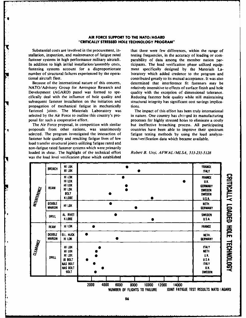
AIR FORCE SUPPORT TO THE NATO/AGARD"CRITICALLY STRESSED HOLE TECHNOLOGY PROGRAM"
Substantial costs are involved in the procurement, in- that there were few differences, within the range of- stallation, inspection, and maintenance of fatigue rated testing frequencies, in the accuracy of loading or corn-
fastener systems in high performance military aircraft. parability of data among the member nation par-In addition to high initial installation/assembly costs, ticipants. The load verification phase utilized equip-fastening systems account for a disproportionate ment specifically designed by the Materials La-number of structural failures experienced by the opera- boratory which added credence to the program and
, tional aircraft fleet. contributed greatly to its mutual acceptance. It was alsoBecause of the international nature of this concern, determined that interference fit fasteners may be
NATO/Advisory Group for Aerospace Research and relatively insensitive to effects of surface finish and holeDevelopment (AGARD) panel was formed to spe- quality with the exception of dimensional tolerance.cifically deal with the influence of hole quality and Reducing fastener hole quality while still maintainingsubsequent fastener installation on the initiation and structural integrity has significant cost savings implica-
* propagation of mechanical fatigue in mechanically tions.fastened joints. The Materials Laboratory was The impact of this effort has been truly internationalselected by the Air Force to outline this country's pro- in nature. One country has changed its manufacturingposal for such a cooperative effort. processes for highly stressed holes to eliminate a costly
The Air Force proposal, in competition with similar but ineffective broaching process. All participatingproposals from other nations, was unanimously countries have been able to improve their spectrumselected. The program investigated the interaction of fatigue testing methods by using the load analyza-fastener hole quality and resulting fatigue lives of low tion/verification data which became available.load transfer structural joints utilizing fatigue rated andnon-fatigue rated fastener systems which were primarilyloaded in shear. The highlight of the technical effort Robert B. Urzi, AFWAL/MLSA, 513-255-5128was the load level verification phase which established
HI LOK 0 FRANCEBROACH HI LOK 0 ITALY
C,3HI LOK FRANCEHI LOK 0 U.K.
Sm REAM HI LOK GERMANYHI LOK •SWEDENBOLT 0 SWEDEN
I K-LOBE 0 U.S.A.
DOUBLE HI LOK 0 NETH.MARGIN H GERMANY C
BRILL AL. RIVET 0 SWEDENK-LOBE 0 U.S.A. "
REAM HI LOK 0 FRANCE
DOUBLE B.L. HUCK 0 NETH. "MARGIN HI LOK 6 GERMANY
MHI LOK ITALY C3HI LOK 0 NETH.HI LO. UXK. 2C
DRILL HUJO BOLT 0 U.SA. I'-NAS BOLT 0 ITALYNAS BOLT 0 U.K.
BOLT 0 SWEDEN
2000 4000 6000 8000 10000 12000 14000
NUMBER OF FLIGHTS TO FAILURE JOINT FATIGUE TEST RESULTS NATO I AGARD
56

F-16 LAMINATED CANOPY
The F-16 canopy consists of fusion-bonded one-piece materials and process conditions required to producemonolithic polycarbonate having a thin polymeric acceptable laminated F-16 canopies. Most importantly,protective coating on the external and internal a versatile tooling concept was established which per-surfaces. Materials Laboratory and the F-16 SPO mits a range of laminate thickness selection and preciserecognized that this approach entailed a certain degree control of laminate cross-section reduction duringof risk. Consequently, a manufacturing methods pro- stretch formulation with resultant outstanding opticalgram was initiated to develop a laminated configuration properties in the final curved configuration. Theconcept as a back-up to the monolithic coated polycar- availability of this proven manufacturing process andbonate F-I 6 canopy. The objective of the contractual ef- continued service-life problems with the coated polycar-fort was to establish cost effective manufacturing pro- bonate F-16 canopy has resulted in recent productioncesses, tooling, and inspection procedures for producing awards for initial GFE purchase of F-16 laminateda compound curvature, laminated one-piece canopy canopies. Based upon extensive service performance ex-meeting all F-16 canopy specification requirements. A perience of acrylic canopies in other aircraft, it is ex-service proven protective acrylic outer face-ply was used pected that a many-fold increase in service life will bebonded with an interlayer to the fusion-bonded polycar- obtained for the acrylic faced polycarbonate F-16bonate structural inner-ply. canopies, with a very significant savings in life-cycle
The very large surface area, the complex wrap-around cost of $175 million for the Air Force's entire 1,388curvature of the F-16 canopy, and the stringent optical plane buy.requirements precluded the use of any known state ofthe art processes. A manufacturing methods effort wascompletely successful in establishing a laminate-and- Sidney Litvak, AFWAL/MLTN, 513-255-7361then-form process including control limits on the
* FORWARD CANOPYCROSS SECTION 1 ":
PLEX 11 FACE PLY All
.125 THICK
POLYCAROONATEITAE.625 THICK
S .100
-- INTERLAYER ,100 THICK
57
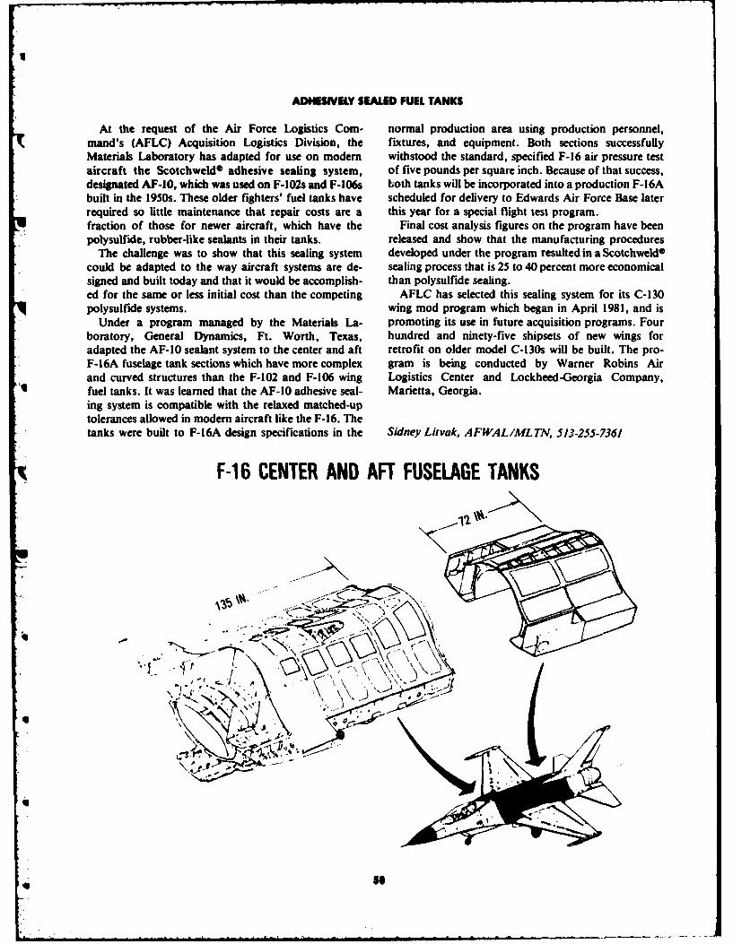
ADHESIVELY SEALED FUEL TANKS
At the request of the Air Force Logistics Com- normal production area using production personnel,mand's (AFLC) Acquisition Logistics Division, the fixtures, and equipment. Both sections successfullyMaterials Laboratory has adapted for use on modem withstood the standard, specified F-16 air pressure testaircraft the Scotchweld® adhesive sealing system, of five pounds per square inch. Because of that success,designated AF-10, which was used on F-102s and F-106s both tanks will be incorporated into a production F-16Abuilt in the 1950s. These older fighters' fuel tanks have scheduled for delivery to Edwards Air Force Base laterrequired so little maintenance that repair costs are a this year for a special flight test program.fraction of those for newer aircraft, which have the Final cost analysis figures on the program have beenpolysulfide, rubber-like sealants in their tanks. released and show that the manufacturing procedures
The challenge was to show that this sealing system developed under the program resulted in a Scotchweld ®
could be adapted to the way aircraft systems are de- sealing process that is 25 to 40 percent more economicalsigned and built today and that it would be accomplish- than polysulfide sealing.ed for the same or less initial cost than the competing AFLC has selected this sealing system for its C-130polysulfide systems. wing mod program which began in April 1981, and is
Under a program managed by the Materials La- promoting its use in future acquisition programs. Fourboratory, General Dynamics, Ft. Worth, Texas, hundred and ninety-five shipsets of new wings foradapted the AF-10 sealant system to the center and aft retrofit on older model C-130s will be built. The pro-F-16A fuselage tank sections which have more complex gram is being conducted by Warner Robins Airand curved structures than the F-102 and F-106 wing Logistics Center and Lockheed-Georgia Company,
A fuel tanks. It was learned that the AF-10 adhesive seal- Marietta, Georgia.ing system is compatible with the relaxed matched-uptolerances allowed in modern aircraft like the F-16. Thetanks were built to F-16A design specifications in the Sidney Litvak, AFWAL/ML TN, 513-255-7361
F-16 CENTER AND AFT FUSELAGE TANKS
%
x', - "V X \ "
', k
[5S

MACHINE TOOL,... 3K FORCE
The most comprehensive study of machine tool the Conference included major addresses by Dr. Ardentechnology ever undertaken in the United States has just L. Bement (USDRE/R&AT) and Mr. Rueben J. Jensenbeen completed by the International Machine Tool Task (Executive Vice President, General Motors Corpora-Force (MTTF) as a result of a 30-month project tion). Heavy coverage in the technical press was evident,sponsored by the Materials Laboratory and per- including a special issue of American Machinist, issuedformed by Lawrence Livermore Laboratory. The pro- coincident with the conference, which devoted 23 pagesgram results were presented at a conference held in to its analysis of the MTTF project. It summarized itsChicago, Illinois, for 700 attendees from industry, findings as follows: "from 30 months of work comes aacademic, and government sectors. A comprehensive remarkable report on current technology, trends, and5-volume report provides the primary documentation directions for R&D. It will be debated.., and mined forfor the project, which studied and assessed the interna- information ... for years." The 5-volume reports aretional state of the art in this field and established the available from the National Technical Information Ser-basis for follow-up planning on technology develop- vice, under report number UCRL 52960-1,2,3,4,5.ment and institutional change in this area of fundamen-tal economic importance. Technical scope of the MTTFcovered machine tool mechanics, controls and accuracy, Rosann Stach, AFWAL/MLTM, 513-255-2413and systems management and utilization. Highlights of
164.[U'
Ui11

ISOTHERMAL FORGING OF F100 BLADES
Material and energy savings and increased productivi- low cost IN-100 forging dies by advanced application ofty were goals of isothermal forging of F100 blades. The CAD/CAM die design and manufacture. Adequate dieprocess was demonstrated by TRW, Inc. by the produc- and lubricant elevated temperature capabilities weretion of more than 300 F100 engine first stage fan blades. demonstrated in an exceedingly harsh forging environ-A substantial data base was established in blade dimen- ment of 1760 0F. This net shape technology has shownsional reproducibility and metallurgical quality, forging that isothermal forging is material and energy efficientlubricant and die performance, and process cost say- and is also amenable to a high productivity processingings. Excellent blade airfoil dimensional reproducibility sequence. The buy-to-fly ratio is 1.83 for the programof ± .003 inch for the isothermal forging process was component, which accomplished a materials savings inestablished. Despite the Ti-8AI-IMo-IV component excess of three pounds per blade over the present pro-alloy's extreme resistance to being forged conventional- duction method. Material, energy, and productivity im-ly, completely adequate metallurgical quality resulted provements should result in a 20-percent cost savingsfrom isothermal processing. Isothermal forging of other for the program component.titanium alloy blades, such as Ti-6A1-4V, would,therefore, be even more easily adaptable to the process.Excellent performance was obtained from the relatively Robert i. Ondercin, AFWAL/MLTM, 513-255-2413
0
-
U
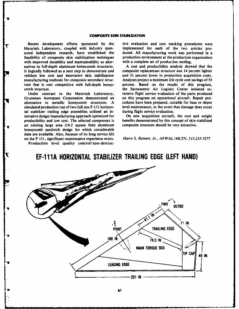
COMPOSITE SKIN STABILIZATION
Recent development efforts sponsored by the tive evaluation and cost tracking procedures wereMaterials Laboratory, coupled with industry spon- implemented for each of the two articles pro-sored independent research, have established the duced. All manufacturing work was performed in afeasibility of composite skin stabilization techniques production environment at the production organizationwith improved durability and maintainability as alter- with a complete set of production tooling.natives to full-depth aluminum honeycomb structures. A cost and producibility analysis showed that theIt logically followed as a next step to demonstrate and composite replacement structure was 14 percent lightervalidate low cost and innovative skin stabilization and 21 percent lower in production acquisition costs.manufacturing methods for composite secondary struc- Analyses project a minimum life cycle cost savings of 53ture that is cost competitive with full-depth honey- percent. Based on the results of this program,comb structure. the Sacramento Air Logistic Center initiated ex-
Under contract to the Materials Laboratory, tensive flight service evaluation of the parts producedGrumman Aerospace Corporation demonstrated an on this program on operational aircraft. Repair pro-alternative to metallic honeycomb structures. A cedures have been prepared, suitable for base or depotsimulated production run of two full size F-I I horizon- level maintenance, in the event that damage does occurtal stabilizer trailing edge assemblies utilized an in- during flight service evaluation.novative design/manufacturing approach optimized for On new acquisition aircraft, the cost and weightproducibility and low cost. The selected component is benefits demonstrated by this concept of skin stabilizedan existing large area (14.2 square feet) aluminum composite structure should be very attractive.honeycomb sandwich design for which considerabledata are available. Also, because of its long service lifeon the F-i 1, significant maintenance experience exists. Harry S. Reinert, Jr., AFWAL/MLTN, 513-255-7277
Production level quality control/non-destruc-
EF-111A HORIZONTAL STABILIZER TRAILING EDGE (LEFT HAND)
(aOUTBD
PIVOT TRAILING EDGE
180 IN. ,78.0 IN
MAIN TORQUE BOXTIP CAP 49 IN.
• • LEADING EDGE
201 IN. I
-i1

U
MIL-H43282-FIRE RESISTANT HYDRAULIC FLUID FOR AEROSPACE APPLICATIONS
The successful development of MIL-H-83282 by reliability aspects.the Materials Laboratory provided by the Air Force In addition to utilization in Air Force aircraft,with a fire-resistant hydraulic fluid for application in MIL-H-83282 has been adopted by the Army and Navycurrent aircraft. This hydraulic fluid, which has for use in their aircraft and is used in NASA's Spacesignificantly improved fire resistance over the previous Shuttle. The addition of a rust inhibitor tostandard hydraulic fluid, MIL-H-5606, has recently MIL-H-83282 resulted in the development ofbeen adopted for use as a direct replacement requiring MIL-H-46170, another fire resistant hydraulic fluid
no component retrofit, in all Air Force aircraft which which has been adopted for use by the Army in theirhave transitioned to the Air Force Logistics Command ground vehicles (e.g., the M-l and M-60 battle tanks).
except the B-52, KC-135, and the few aircraft designed MIL-H-83282 has been selected as the hydraulic fluid into use phosphate ester hydraulic fluids. In addition to the Navy's experimental high pressure (8000 psi) aircraftthe significant reductions in aircraft lost or damaged as hydraulic system advanced development program.a result of hydraulic fluid fires (>100 million between The synthetic hydrocarbon chemistry developed for1970 and 1975) anticipated by converting the fleet to this hydraulic fluid development program has providedMIL-H-83282, its improved lubricity and shear stability spin-off in the civilian sector in the area of syntheticover MIL-H-5606 will result in improved hydraulic based crankcase oils for the automotive industry.system performance and longer component life. Theseadvantages will result in significant, but difficult todocument, cost savings from aircraft maintenance and Carl E. Snyder, AFWAL/MLBT, 513-255-5731
. GUNFIRE IGNITION RESISTANCE
.50 CAL. ARMOR PIERCING INCENDIARY AMNITION
MIL-H-566MLH-83 2
62

AIRCRAFT MANUFACTURING QUALITY ASSURANCE USING PHOTOGRAMMETRIC TECHNIQUES
Historically, the aircraft industry has controlled the phases. The first was to establish the utility and cost ef-dimensional integrity of major aircraft component fectiveness of the photogrammetric technology as ap-assembly tools by means of component master gages plied to complex tools. The second phase was a compo-(COMG). Periodically, the COMG, which is used in nent assembly coordination study which employedmanufacturing the tool, is reinstalled to assure fidelity stereo photogrammetric techniques. The final phaseto the original configuration-a process called periodic evaluated the parameters for use of photogrammetryinspection (PI). In addition to the labor required for the for very large aircraft tooling.PI, there are penalties of production downtime and lost Photogrammetric PI has now been implemented onproductivity. Photogrammetric techniques verify the 36 assembly tools, of eight families, for the F-16. Thesetool alignment with little or no production downtime include complex assemblies such as the center fuselageand 1/4 to 1/10 the cost of conventional Pl. Theodolite and aft fuselage. As of September 1981, photogram-techniques are u ,ed to supplement photography for metric PI has been accomplished 38 times on variousestablishing metrology baselines and for areas requiring tools with a cost savings of $120,732.06. It is estimatedgreater accuracy. that the cost avoidance using photogrammetry during
General Dynamics, Fort Worth Division, under the F-16 production program will total $2.5 million.contract to the Materials Laboratory, has estab-ished the use of photogrammetric metrology for
routine assembly tool aligrment verification. Edward Wheeler, AFWAL/MLTM, 513-255-2413The program was conducted in three evaluation
qD
... I . . .....-
q
qu
L'3
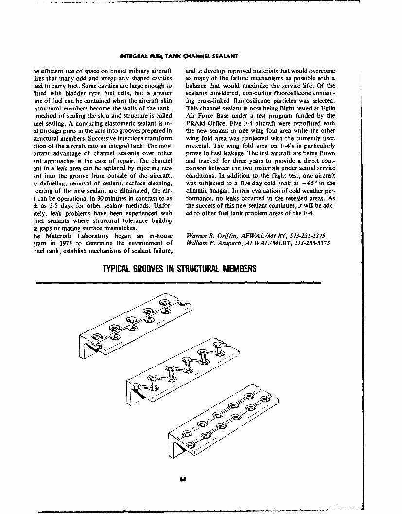
INTEGRAL FUEL TANK CHANNEL SEALANT
he efficient use of space on board military aircraft and to develop improved materials that would overcomeiires that many odd and irregularly shaped cavities as many of the failure mechanisms as possible with ased to carry fuel. Some cavities are large enough to balance that would maximize the service life. Of the'itted with bladder type fuel cells, but a greater sealants considered, non-curing fluorosilicone contain-.me of fuel can be contained when the aircraft skin ing cross-linked fluorosilicone particles was selected.structural members become the walls of the tank. This channel sealant is now being flight tested at Eglinmethod of sealing the skin and structure is caged Air Force Base under a test program funded by thereel sealing. A noncuring elastomeric sealant is in- PRAM Office. Five F-4 aircraft were retrofitted with-d through ports in the skin into grooves prepared in the new sealant in ore wing fold area while the otheritructural members. Successive injections transform wing fold area was reinjected with the currently used:tion of the aircraft into an integral tank. The most material. The wing fold area on F-4's is particularlyDrtant advantage of channel sealants over other prone to fuel leakage. The test aircraft are being flownant approaches is the ease of repair. The channel and tracked for three years to provide a direct com-ant in a leak area can be replaced by injecting new parison between the two materials under actual serviceant into the groove from outside of the aircraft. conditions. In addition to the flight test, one aircraft:e defueling, removal of sealant, surface cleaning, was subjected to a five-day cold soak at -65 o in thecuring of the new sealant are eliminated, the air- climatic hangar. In this evaluation of cold weather per-
t can be operational in 30 minutes in contrast to as formance, no leaks occurred in the resealed areas. As:h as 3-5 days for other sealant methods. Unfor- the success of this new sealant continues, it will be add-itely, leak problems have been experienced with ed to other fuel tank problem areas of the F-4.reel sealants where structural tolerance buildup;e gaps or mating surface mismatches.he Materials Laboratory began an in-house Warren R. Griffin, AFWAL/MLBT, 513-255-5375gram in 1975 to determine the environment of William F. Anspach, AFWAL/MLBT, 513-255-5375fuel tank, establish mechanisms of sealant failure,
TYPICAL GROOVES IN STRUCTURAL MEMBERS

II
COMPOSITE SKIN FABRICATION
The Materials Laboratory recognized the desira- production of the ten trailing edges provided valuablebility of finding alternatives to full-depth honeycomb insight into the high cost areas of composite production.metallic structures that are more durable and lower in Learning curves developed from the cost tracking datalife cycle cost. A manufacturing methods program was were used to verify that the composite components areinitiated at Vought Corporation, Dallas, Texas, to cost competitive with conventional metal honeycombestablish and validate a low-cost innovative manufac- components in volume production. A repair manual forturing method for producing skin-stabilized composite the composite skin-stabilized trailing edge wedge wasstructures which are cost and weight competitive with prepared that specifies the structure as well as damagefull-depth honeycomb metallic structure. In addition, criticality for Air Logistics Center needs.shop floor production personnel produced ten T-38 The Air Logistics Center has purchased an additionalaileron trailing edges that will be installed on Air Force 20 trailing edges, which will be used along with theaircraft to obtain in-service data on the durability of the original ten, in a service evaluation program. Thecomposite structure. manufacturing methods program has provided a viable
The manufacturing method incorporates a non- cost-competitive alternative to the currently usedautoclave cure processing technique and integral curing honeycomb structure.of the skins and substructure. The required curepressure is provided and controlled by use of anelastomeric bladder tool. Detailed cost tracking during Harry S. Reinert, AFWAL/MLTN, 513-255-7277
I d

COATINGS FOR SPACECRAFT CHARGING CONTROL
Anomalous spacecraft operation due to electrical coatings can be reproducibly deposited and providecharge build-up and subsequent discharge is a problem highly stable semi-conducting properties with solar ab-when operating in the synchronous earth orbit environ- sorptances of one or two percent. The coatings, whenment. These discharges may cause disruptions or even applied to glass, FEP Teflon, and Kapton, have con-catastrophic damage to electronic components as well as sistently yielded resistance values in the low kilo ohm/degradation of thermal control materials. Charge con- square range.trol is of special concern for future systems with ex- The charge control characteristics of the coatingspected service lives of seven to ten years. have been evaluated under simulated substorm condi-
Thin coatings of indium tin oxide (ITO) and indium tions. Measurements of surface potentials during andoxide (10) have been shown to be space stable, with low after irradiation by electrons up to 25 key shows an ef-electrical resistance and solar absorptance. Efforts to fectively grounded surface with no evidence of chargereproducibly deposit these coatings on typical thermal build-up or discharging. Discharges were also notcontrol materials have also been successful. The observed on samples which had previously been exposeddevelopment and evaluation by the Materials La- to heat, humidity, chemical spray, and thermal cyclingboratory of ITO and 10 coatings have generated a tests before electron irradiation. The programs con-great deal of confidence in their charge control ability ducted by the Materials Laboratory have yieldedand have established the processing parameters required innovative charge control techniques for criticalto achieve a conductive, yet high transmittance, coating. satellite systems.
Coating thicknesses between 100A and 1000A havebeen explored to determine the optimal value. Storage,handling, and environmental testing indicate that 200A Harry S. Reinert, AFWAL/MLTN, 513-255-7277
ELECTRICAL AND OPTICAL CHARACTERISTICS OF 90% In203 I10% SnO2 (ITO) COATED KAPTON (2 mil)
ITO SURFACE (VISIBLE) OPTICAL CONSTANTSTHICKNESS (A) RESISTIVITY K2 /0" TRANSMISSION a E. RATIO
900 .45 -.75 56.6 .311 .546 .569
900 .45 -.75 53.1 .297 .583 .509
500 3 -7 59.4 .276 .565 .488
500 3 -7 58.7 .274 .559 .490
250 80 -150 59.9 .293 .538 .540
250 80 -150 59.9 .284 .540 .548
UNCOATED 10" 60.06 .284 .539 .524__-

CARBON-CARBON COMPOSITES FOR MISSILES
Carbon-carbon composites are newly developed high the thermal recession of a carbon-phenolic nose tip andtemperature structural materials currently being used excellent shape stability during missile reentry, thus pro-for a number of critical aerospace applications. Ad- viding increased accuracy and enhanced survivability.vanced missile reentry systems use carbon-carbon com- The material is now used on the Minuteman Ill Markposites for shape-stable nose tips. Carbon-carbon is 12A reentry vehicle, and it is being used to replace theused for the Space Shuttle's nose cap and leading edges. nose tip material presently on the Mark 12.Large solid-propellant rocket motors will use these ad- The carbon-carbon composites are uniquely suited tovanced composites in the integrated throat and entrance the extreme environments encountered at the nozzle(ITE) section of the nozzle, such as the 500-lb ITE for throat. Their low erosion and high durability in hot pro-the first stage of the MX missile. pellant gases permits highly reliable and lightweight
The carbon-carbon composites are composed of a nozzles for solid propellant motors. The carbon-carbongraphite matrix reinforced with graphite fibers in a composites provide highly promising solutions for MXthree-dimensional array. They were first fabricated and Trident II nozzle throats. All three MX propulsionunder the Materials Laboratory sponsorship in 1967. stage contractors are using one-piece carbon-carbonThe Laboratory continued to develop the composites nozzles in the full scale engineering development pro-with the Air Force Ballistic Missile Office subsequently gram.entering advanced development with these newmaterials. Donald L. Schmidt, AFWAL/MLBE, 513-255-5767
The new carbon-carbon missile nose tip has one-half Scott Theibert, AFWAL/MLBE, 513-255-5767
UX
•
qm 67
U
U"
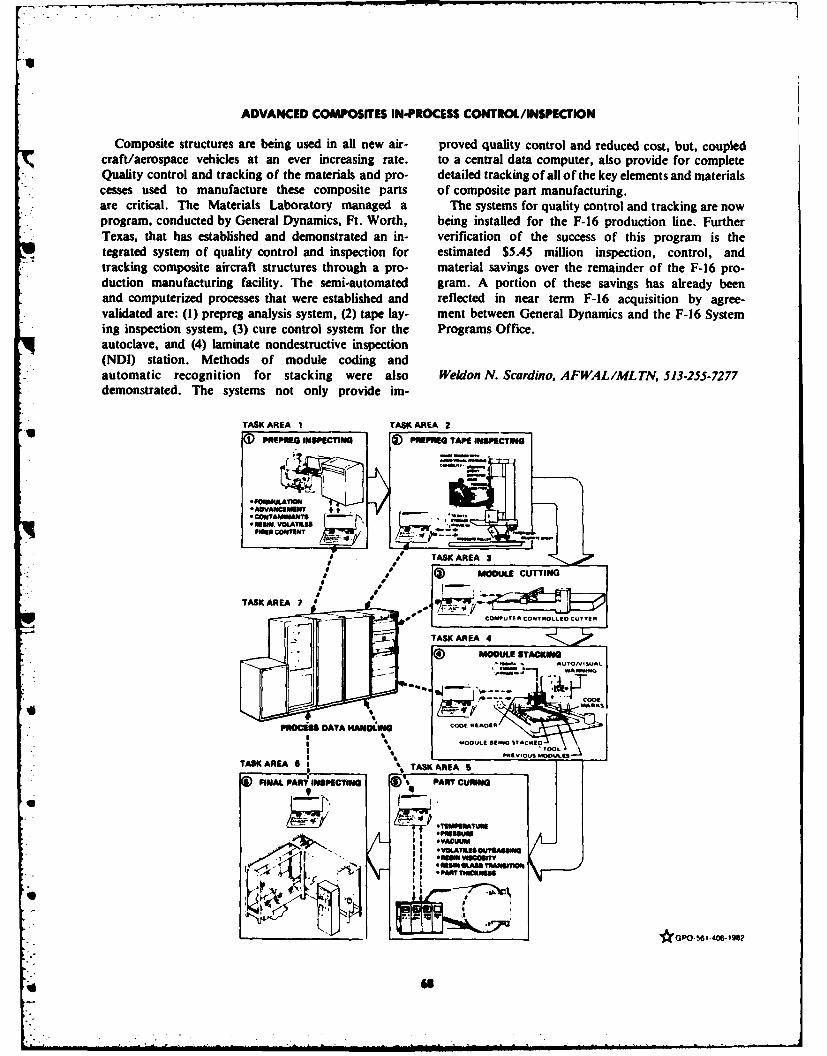
ADVANCED COMPOSITES IN-PROCESS CONTROL/INSPECTION
Composite structures are being used in all new air- proved quality control and reduced cost, but, coupledcraft/aerospace vehicles at an ever increasing rate. to a central data computer, also provide for complete
- Quality control and tracking of the materials and pro- detailed tracking of all of the key elements and materialscesses used to manufacture these composite parts of composite part manufacturing.are critical. The Materials Laboratory managed a The systems for quality control and tracking are nowprogram, conducted by General Dynamics, Ft. Worth, being installed for the F-16 production line. FurtherTexas, that has established and demonstrated an in- verification of the success of this program is thetegrated system of quality control and inspection for estimated $5.45 million inspection, control, andtracking composite aircraft structures through a pro- material savings over the remainder of the F-16 pro-duction manufacturing facility. The semi-automated gram. A portion of these savings has already beenand computerized processes that were established and reflected in near term F-16 acquisition by agree-validated are: (I) prepreg analysis system, (2) tape lay- ment between General Dynamics and the F-16 Systeming inspection system, (3) cure control system for the Programs Office.autoclave, and (4) laminate nondestructive inspection(NDI) station. Methods of module coding andautomatic recognition for stacking were also Weldon N. Scardino, AFWAL/MLTN, 513-255-7277demonstrated. The systems not only provide im-
TASK AREA 1 TASK AREA 2SPmprNa SPECT I ) PRPe TAPE oNcTa
**ADVANC211 *t ,:COUi1AMUWkTSRIU VOLATILINI
Plan CONeNT /Y 4 '-.'.
TASK AREA 3
MODULE CUTTIG
TASK AREA 7 •
PROCES DACOTAU E CONTOL LEO CUTTER
TASK AREA 4MODULE STACKING
' R M U D A T A H A N D L 1N G C O O ' " DI~R j
T A , * TASKARAFINAL ;AI ICTING PART CURIN
I *VOLATUSOUTEDIA
wm TVcmr•i *Um ycgt
•~AW _ om--"GPO-
6 -4 '6-19
-2