IHE Radiology Technical Framework Supplement 2006 … · IHE Radiology Technical Framework...
50
ACC, HIMSS and RSNA Integrating the Healthcare Enterprise IHE Radiology Technical Framework Supplement 2006-2007 Mammography Image (MAMMO) Integration Profile Draft for Trial Implementation April 13, 2006 Copyright © 2006: ACC/HIMSS/RSNA
Transcript of IHE Radiology Technical Framework Supplement 2006 … · IHE Radiology Technical Framework...

ACC, HIMSS and RSNA Integrating the Healthcare Enterprise
IHE Radiology Technical Framework Supplement 2006-2007
Mammography Image (MAMMO) Integration Profile
Draft for Trial Implementation April 13, 2006
Copyright © 2006: ACC/HIMSS/RSNA

IHE Technical Framework Supplement – MAMMO Profile Draft for Trial Implementation _________________________________________________________________________
__________________________________________________________________________
Radiology: Mammography Image
Rev. 1.1: TI - 2006-04-13 Copyright © 1997-2006: ACC/HIMSS/RSNA
1
Contents 1. Foreword.................................................................................................................................. 2 2. Introduction.............................................................................................................................. 5
2.1. Open Issues and Questions............................................................................................... 5 2.2. Closed Issues .................................................................................................................... 5
3. Profile Abstract........................................................................................................................ 8 4. GLOSSARY ............................................................................................................................ 8
Vol. 1 1 Changes to Sections 1 – 1.X ........................................................................................................ 9
1.7 History of Annual Changes.................................................................................................. 9 2 Integration Profiles.................................................................................................................. 9 2.1.n Mammography Image ....................................................................................................... 9
19 Mammography Image Integration Profile ............................................................................... 10 19.1 Actors/ Transactions ........................................................................................................ 10 19.2 Mammography Image Integration Profile Options .......................................................... 12 19.3 Mammography Image Profile Process Flow.................................................................... 12
Vol. 2 2.2 DICOM Usage Conventions .............................................................................................. 14 4.8 Modality Images Stored ..................................................................................................... 15 4.16 Retrieve Images................................................................................................................ 22 4.23 Print Request with Presentation LUT .............................................................................. 34 4.23.1 Scope............................................................................................................................. 34
Vol. 3 4.43 Evidence Document Stored ............................................................................................ 39 4.43.1 Scope......................................................................................................................... 39 4.43.2 Use Case Roles ......................................................................................................... 39 4.43.3 Referenced Standards................................................................................................ 40 4.43.4 Interaction Diagram .................................................................................................. 40 4.44 Query Evidence Documents ........................................................................................... 43 4.44.1 Scope......................................................................................................................... 43 4.44.2 Use Case Roles ......................................................................................................... 43 4.44.3 Referenced Standards................................................................................................ 43 4.44.4 Interaction Diagram .................................................................................................. 44 4.45 Retrieve Evidence Documents .................................................................................. 46 4.45.1 Scope......................................................................................................................... 46 4.45.2 Use Case Roles ......................................................................................................... 46 4.45.3 Referenced Standards................................................................................................ 46 4.45.4 Interaction Diagram .................................................................................................. 47

IHE Technical Framework Supplement – MAMMO Profile Draft for Trial Implementation _________________________________________________________________________
__________________________________________________________________________
Radiology: Mammography Image
Rev. 1.1: TI - 2006-04-13 Copyright © 1997-2006: ACC/HIMSS/RSNA
2
1. Foreword Integrating the Healthcare Enterprise (IHE) is an initiative designed to stimulate the integration of the information systems that support modern healthcare institutions. Its fundamental objective is to ensure that in the care of patients all required information for medical decisions is both correct and available to healthcare professionals. The IHE initiative is both a process and a forum for encouraging integration efforts. It defines a technical framework for the implementation of established messaging standards to achieve specific clinical goals. It includes a rigorous testing process for the implementation of this framework. And it organizes educational sessions and exhibits at major meetings of medical professionals to demonstrate the benefits of this framework and encourage its adoption by industry and users.
The approach employed in the IHE initiative is not to define new integration standards, but rather to support the use of existing standards, HL7, DICOM, IETF, and others, as appropriate in their respective domains in an integrated manner, defining configuration choices when necessary. IHE maintain formal relationships with several standards bodies including HL7, DICOM and refers recommendations to them when clarifications or extensions to existing standards are necessary.
This initiative has numerous sponsors and supporting organizations in different medical specialty domains and geographical regions. In North America the primary sponsors are the American College of Cardiology (ACC), the Healthcare Information and Management Systems Society (HIMSS) and the Radiological Society of North America (RSNA). IHE Canada has also been formed. IHE Europe (IHE-EUR) is supported by a large coalition of organizations including the European Association of Radiology (EAR) and European Congress of Radiologists (ECR), the Coordination Committee of the Radiological and Electromedical Industries (COCIR), Deutsche Röntgengesellschaft (DRG), the EuroPACS Association, Groupement pour la Modernisation du Système d'Information Hospitalier (GMSIH), Société Francaise de Radiologie (SFR), Società Italiana di Radiologia Medica (SIRM), the European Institute for health Records (EuroRec), and the European Society of Cardiology (ESC). In Japan IHE-J is sponsored by the Ministry of Economy, Trade, and Industry (METI); the Ministry of Health, Labor, and Welfare; and MEDIS-DC; cooperating organizations include the Japan Industries Association of Radiological Systems (JIRA), the Japan Association of Healthcare Information Systems Industry (JAHIS), Japan Radiological Society (JRS), Japan Society of Radiological Technology (JSRT), and the Japan Association of Medical Informatics (JAMI). Other organizations representing healthcare professionals are invited to join in the expansion of the IHE process across disciplinary and geographic boundaries.
The IHE Technical Frameworks for the various domains (IT Infrastructure, Cardiology, Laboratory, Radiology, etc.) defines specific implementations of established standards to achieve

IHE Technical Framework Supplement – MAMMO Profile Draft for Trial Implementation _________________________________________________________________________
__________________________________________________________________________
Radiology: Mammography Image
Rev. 1.1: TI - 2006-04-13 Copyright © 1997-2006: ACC/HIMSS/RSNA
3
integration goals that promote appropriate sharing of medical information to support optimal patient care. It is expanded annually, after a period of public review, and maintained regularly through the identification and correction of errata. The current version for these Technical Frameworks may be found at www.rsna.org/IHE or http://www.himss.org/IHE.
The IHE Technical Framework identifies a subset of the functional components of the healthcare enterprise, called IHE Actors, and specifies their interactions in terms of a set of coordinated, standards-based transactions. It describes this body of transactions in progressively greater depth. The volume I provides a high-level view of IHE functionality, showing the transactions organized into functional units called Integration Profiles that highlight their capacity to address specific clinical needs. The subsequent volumes provide detailed technical descriptions of each IHE transaction.

IHE Technical Framework Supplement – MAMMO Profile Draft for Trial Implementation _________________________________________________________________________
__________________________________________________________________________
Radiology: Mammography Image
Rev. 1.1: TI - 2006-04-13 Copyright © 1997-2006: ACC/HIMSS/RSNA
4
Date: <April 13, 2006>
These ”boxed” instructions for the author to indicate to the Volume Editor how to integrate the relevant section(s) into the overall Technical Framework
Note that DICOM data element tags for Gantry ID (gggg,eee2) and Pixel Padding Value Range (0028,eee1) will be completed in this document as soon as the relevant DICOM CPs are completed and the tags have been assigned.

IHE Technical Framework Supplement – MAMMO Profile Draft for Trial Implementation _________________________________________________________________________
__________________________________________________________________________
Radiology: Mammography Image
Rev. 1.1: TI - 2006-04-13 Copyright © 1997-2006: ACC/HIMSS/RSNA
5
5
10
2. Introduction
2.1. Open Issues and Questions
2.2. Closed Issues 1. Though Device Serial Number was proposed rather than Station Name to be used to identify a particular device for the purpose of image annotation for MQSA, since for DX systems they will likely refer to the same device, and for CR it is necessary to identify the mammography device rather than the plate reader (whose Station Name is likely to be its DICOM AE Title); though in many cases Station Name is likely to be a network hostname or DICOM AE Title, and hence is subject to the vagaries of network configuration, users have expressed a preference for this rather than a less recognizable and more cryptic serial number. The issue of the distinguishing the acquisition unit from the CR plate reader has been addressed by a new attribute Gantry ID (gggg,eee2), to be used in place of Station Name when present.
2. It is desirable to be able to selectively retrieve images based on their SOP Class UID in order to distinguish between For Processing and For Presentation images; though SOP Class UID is an optional query key at the IMAGE level in DICOM, the IHE Query Images Transaction already makes this a mandatory matching and return key, obviating the need for any mammography-specific additional requirement. It goes without saying that all Image Manager/Archives are reuired to support all levels of query request (STUDY, SERIES, IMAGE) for the appropriate query model, since this is a DICOM requirement, though one that is allegedly commonly violated.
15
20
25
30
3. The list of attributes to be available for display has been extended to include technique attributes to meet the requirements called out in the ACR Quality Manual (though they are not required by MQSA).
4. No dependencies on workflow profiles (SWF, RWF, PPWF) are defined, and are left to the Deployment Handbook for the time being.
5. Re-processing workflow is not defined, whether it be performed on the Acquisition Modality, Image Display or other device. Image Displays are not required to support “For Processing” images.
6. No specific requirements for Portable Data for Imaging (PDI) are specified, meaning that whilst mammography objects may be stored on media, the choice of which types of objects (“For Processing”, and “For Presentation” Mammography Images, Mammo CAD SR, Mammography SR reports, Presentation States or Key Image Notes), is at the discretion of the implementor.

IHE Technical Framework Supplement – MAMMO Profile Draft for Trial Implementation _________________________________________________________________________
__________________________________________________________________________
Radiology: Mammography Image
Rev. 1.1: TI - 2006-04-13 Copyright © 1997-2006: ACC/HIMSS/RSNA
6
5
10
15
20
25
30
7. Mammography-specific reporting workflow is not defined, nor are the objects in which a mammography report might be encoded (such as DICOM SR objects with the Breast Image Reporting template).
8. No mechanism for getting the “for processing” images to the CAD system is explicitly specified
9. An Image Display is not required to be a Print Composer.
10. No dependency on CPI is specified – instead, Image Displays are required to be calibrated. Acquisition Modalities are not.
11. No attempt is made to “standardize” particular choices of hanging protocols; examples are provided only as a means of describing the scope of testing of the use of the specified attributes to drive hanging protocols.
12. Relative X-Ray Dose is specified as a means of indicating the actual exposure, recognizing that the interpretation of the value is vendor-specific. Ideally a standardized scale could be used across all vendors, such as that proposed by AAPM TG#116 DR Exposure Index. It is understood that some vendors are concerned about the use of information in this value with respect to either feedback to the user that leads to a change in technique parameters, or as an inappropriate source of information about the dose delivered to the patient. It is felt that this is best addressed by a CP to the definition of this attribute in the DICOM standard to address these issues, rather than not requiring its use in IHE. There is no question amongst the users that feedback of this type of information is vital.
13. Exposure rather than Exposure in uAs is specified, since even though most vendors send both, we only need one, and the former provides sufficient precision for display.
14. No “fit breast to viewport” mode is defined, since this is a complex operation not easily specified and best left to the discretion of the Image Display implementor.
15. Image Displays are required to annotate ratios with respect to displayed versus encoded pixels and true size
16. Image Manager/Archive Actors be able to not only receive but also respond to queries for and return Mammograpy CAD SR objects from Evidence Creators (CAD systems), so that the Image Display can make use of them directly (rather than have them burned in to images or converted into presentation states).
17. An Image Display is required to be able to display a ruler on the screen as a visual cue to indicate physical size
18. The VOI LUT Function attribute is required to be inserted by the Acquisition Modality if the window values are present and not intended to be interpreted as parameters of a linear function.

IHE Technical Framework Supplement – MAMMO Profile Draft for Trial Implementation _________________________________________________________________________
__________________________________________________________________________
Radiology: Mammography Image
Rev. 1.1: TI - 2006-04-13 Copyright © 1997-2006: ACC/HIMSS/RSNA
7
5
10
15
20
25
30
19. It is not within the scope of the profile to require display ratios at other than 1:1 despite research that suggests that other ratios based on the specific characteristics of the detector and display may actually be optimal for viewing.
20. It is not necessary to require display of the interpolation function in use, or to mandate the type of interpolation used.
21. No mechanism is specified for explicitly encoding the extent of the breast area, the mechanism chosen for air supression may assist on detecting the breast area.
22. Partial View support is factored out as a named option.
23. Views derived from View Code Sequence and View Modifier Code Sequence are required to be annotated not with textual code meanings but with the ACR recommended abbreviations
24. Magnification views are not partial views.
25. Patient’s Age and Patient’s Birth Date are required from the Acquisition Modality and required to be made available for display by the Image Display.
26. There is no need for the content profile to address constraints on the content of Mammo CAD SR objects.
27. Display of CAD Marks is defined in the Retrieve Images transaction rather than the Retrieve Evidence Documents transaction (from which there is a reference), in order to have all rendering requirements for the Image Display located in the same place in the document for clarity.
28. Background air suppression is defined to use one of two mechanisms, a single pixel padding value or a range of pixel padding values (which requires a DICOM CP). Acquisition Modalities may use either, Image Displays must support both.
29. The names and display formats to use for the two ratios related to display sized (displayed pixels relative to the number of encoded image pixels, and size of the displayed pixels relative to true size shall be left to the implementors’ discretion.
30. A requirement is present to guard against interpreting priors as current by notification that study date is significantly earlier than current real time date.
31. It is required to flip CAD coordinates based on comparing Patient Orientation when this differs between the (CAD description of) the value in the For Processing as opposed to For Presentation images, and in this scenario Spatial Locations Preserved in the Source Image Sequence of the For Presentation images shall be YES.
32. CAD information displayed should include the manufacturer, algorithm, version, operating point and when CAD fails, including the sub-categories of failure (e.g. calcs not masses).

IHE Technical Framework Supplement – MAMMO Profile Draft for Trial Implementation _________________________________________________________________________
__________________________________________________________________________
Radiology: Mammography Image
Rev. 1.1: TI - 2006-04-13 Copyright © 1997-2006: ACC/HIMSS/RSNA
8
5
10
15
33. If more than one set of CAD objects are available for the same image, then all need to be made available for display at the user’s discretion. This creates a need to also display the date and time that CAD was performed.
34. Specific scenarios for hanging protocols are outside the scope of the profile and may be more appropriately described in the Deployment Handbook.
3. Profile Abstract The Mammography Image Profile specifies how DICOM Mammography images and evidence objects are created, exchanged and used. It describes how Acquisition Modalities transfer Full Field Digital Mammography (FFDM) Images, how CAD systems act as Evidence Creators, and how Image Displays should retrieve and make use of images and CAD results. It defines the basic display capabilities Image Displays are expected to provide, and which attributes should be used to implement those capabilities.
Managing the process of creating, storing and using Mammography Image content is similar to workflow for other image content (e.g. see Scheduled Workflow and Post-Processing Workflow Profiles).
4. GLOSSARY FFDM – Full Field Digital Mammography
MQSA - Mammography Quality Standards Act of 1992

IHE Technical Framework Supplement – MAMMO Profile Draft for Trial Implementation _________________________________________________________________________
__________________________________________________________________________
Radiology: Mammography Image
Rev. 1.1: TI - 2006-04-13 Copyright © 1997-2006: ACC/HIMSS/RSNA
9
5
10
15
Volume 1 – Integration Profiles 1 Changes to Sections 1 – 1.X
1.7 History of Annual Changes Add the following bullet to the end of the bullet list in section 1.7 • Added the Mammography Image Profile
2 Integration Profiles Modify the following paragraph as shown
The Content Profiles describe the creation, storage, management, retrieval and general use of a particular type of content object. Current Content Profiles include: Consistent Presentation of Images, Key Image Notes, NM Image, Mammography Image, Evidence Documents, and Simple Image and Numeric Reports. Additionally, the handling of image content is described inside the Scheduled Workflow Profile. Content Profiles are “workflow neutral”. The profile addresses how the object is created, stored, queried and retrieved, but does not address the workflow management process.
Add Mammography Image to Figure 2-1 and add the following line to Table 2-1
Integration Profile Depends on Dependency Type Comments … … … …
NM Image None None
Mammography Image None None Evidence Documents None None -
… … … …
Add Mammography Image Section 2.1.n
2.1.n Mammography Image
20 The Mammography Image Profile specifies how DICOM Mammography images and evidence objects are created, exchanged and used. It describes how Acquisition Modalities transfer Full Field Digital Mammography (FFDM) Images, how CAD systems act as Evidence Creators, and how Image Displays should retrieve and make use of images and CAD results. It defines the

IHE Technical Framework Supplement – MAMMO Profile Draft for Trial Implementation _________________________________________________________________________
__________________________________________________________________________
Radiology: Mammography Image
Rev. 1.1: TI - 2006-04-13 Copyright © 1997-2006: ACC/HIMSS/RSNA
10
basic display capabilities Image Displays are expected to provide, and which attributes should be used to implement those capabilities.
Add the following section
19 Mammography Image Integration Profile 5
10
15
20
25
30
The Mammography Image Profile specifies how DICOM Mammography images and evidence objects are created, exchanged and used. It describes how Acquisition Modalities transfer Full Field Digital Mammography (FFDM) Images, how CAD systems act as Evidence Creators, and how Image Displays should retrieve and make use of images and CAD results. It defines the basic display capabilities Image Displays are expected to provide, and which attributes should be used to implement those capabilities.
Managing the process of creating, storing and using Mammography Image content is similar to workflow for other image content (e.g., see Scheduled Workflow and Post-Processing Workflow Profiles).
An Image Display that supports the Mammography Image Profile shall support calibration as described in the DICOM Grayscale Standard Display Function (GSDF). The minimum and maximum luminance of the display shall be configurable by the site, within the gamut of the device, for the purpose of conforming to local, regional or national regulatory and other requirements for luminance settings throughout the organization. For example, a site may require that all Image Displays used for primary interpretation be calibrated to the same minimum and maximum luminance.
The Mammography Image Profile is designed to provide faithful and complete storage and retrieval of Mammography data and sufficient display functionality to allow adequate review of current and prior images and CAD results for the purpose of primary interpretation by radiologists. It should also be sufficient for secondary review for referring physicians. It does not address the use of other modalities appropriate for breast imaging such as MR or US.
19.1 Actors/ Transactions Figure 19.1-1 shows the actors directly involved in the Mammography Image Integration Profile and the relevant transactions between them.

IHE Technical Framework Supplement – MAMMO Profile Draft for Trial Implementation _________________________________________________________________________
__________________________________________________________________________
Radiology: Mammography Image
Rev. 1.1: TI - 2006-04-13 Copyright © 1997-2006: ACC/HIMSS/RSNA
11
↓ Query Images [14] ↓ Retrieve Images [16] ↓ Query Evidence Documents [44] ↓ Retrieve Evidence Documents [45]
Evidence Document Stored [43] ↓
↓ Storage Commitment [10]
Evidence Creator
Acquisition Modality
Image Manager
Image Archive
Image Display
Modality Images Stored [8] ↑
↑ Storage Commitment [10]
Print Request with Presentation LUT[RAD-23] ↓
Print Server
Print Composer
Figure 19.1-1. Mammography Image Profile Actor Diagram
Table 19.1-1 lists the transactions for each actor directly involved in the Mammography Image Profile. In order to claim support of this Integration Profile, an implementation must perform the required transactions (labeled “R”). Transactions labeled “O” are optional. A complete list of options defined by this Integration Profile and that implementations may choose to support is listed in Volume I, Section 19.2.
5
Table 19.1-1. Mammography Image Integration Profile - Actors and Transactions
Actors Transactions Optionality Section in Vol. 2/3
Modality Images Stored [RAD-8] R 4.8 Acquisition Modality
Storage Commitment [RAD-10] R 4.10
Evidence Document Stored R 4.43 Evidence Creator
Storage Commitment [RAD-10] R 4.10
Image Manager/Archive Modality Images Stored [RAD-8] R 4.8

IHE Technical Framework Supplement – MAMMO Profile Draft for Trial Implementation _________________________________________________________________________
__________________________________________________________________________
Radiology: Mammography Image
Rev. 1.1: TI - 2006-04-13 Copyright © 1997-2006: ACC/HIMSS/RSNA
12
Section in Actors Transactions Optionality Vol. 2/3
Evidence Document Stored R 4.43
Storage Commitment [RAD-10] R 4.10
Query Images [RAD-14] R 4.14
Retrieve Images [RAD-16] R 4.16
Query Evidence Documents [RAD-44]
R 4.44
Retrieve Evidence Documents [RAD-45]
R 4.45
Query Images [RAD-14] R 4.14 Image Display
Retrieve Images [RAD-16] R 4.16
Query Evidence Documents [RAD-44]
R 4.44
Retrieve Evidence Documents [RAD-45]
R 4.45
Print Composer Print Request with Presentation LUT [RAD-23]
R 4.23
Print Server Print Request with Presentation LUT [RAD-23]
R 4.23
19.2 Mammography Image Integration Profile Options Options that may be selected for this Integration Profile are listed in the table 19.2-1 along with the Actors to which they apply. Dependencies between options when applicable are specified in notes.
5 Table 19.2-1 Evidence Documents - Actors and Options Actor Options Vol & Section
Acquisition Modality Partial View Vol 2 4.8.4.1.2.3.1
Image Archive/Manager No options defined
Image Display Partial View Vol 2 4.16.4.2.2.1.1.7
19.3 Mammography Image Profile Process Flow

IHE Technical Framework Supplement – MAMMO Profile Draft for Trial Implementation _________________________________________________________________________
__________________________________________________________________________
Radiology: Mammography Image
Rev. 1.1: TI - 2006-04-13 Copyright © 1997-2006: ACC/HIMSS/RSNA
13
Perform Acquisition
Image Manager/ Image Archive
Acquisition Modality
Modality Images Stored [8] - Mammo Images
Image Display
Query Images [14]
Retrieve Images [16] - Mammo Images
Present Mammo Images to User
Storage Commitment [10]
Query Evidence Document [44]
Retrieve Evidence Document [45] - Mammo CAD
Present Mammo Images with CAD to User
Perform CAD
Evidence Document Stored [43] - Mammo CAD
Storage Commitment [10]
Evidence Creator
(CAD System)
Figure 19.3-1. Basic Process Flow in Mammography Image Profile
The workflow between the Acquisition Modality and the Evidence Creator that is the CAD device is currently outside the scope of IHE to define.

IHE Technical Framework Supplement – MAMMO Profile Draft for Trial Implementation _________________________________________________________________________
__________________________________________________________________________
Radiology: Mammography Image
Rev. 1.1: TI - 2006-04-13 Copyright © 1997-2006: ACC/HIMSS/RSNA
14
5
Volume 2 - Transactions 2.2 DICOM Usage Conventions For some DICOM transactions described in this document, IHE has strengthened the requirements on the use of selected Type 2 and Type 3 attributes. These situations are explicitly documented in section 4 and in the appendices.
IHE specifically emphasizes that DICOM Type 2 attributes (for instance, Patient Name, Patient ID) shall be transmitted with zero length if the source system does not possess valid values for such attributes; in other words, the source system shall not assign default values to such attributes. The receiving system must be able to handle zero-length values for such attributes.
IHE has defined requirements related to the support for and use of attributes in DICOM 10 storage transactions by both Service Class Users (SCUs) and Service Class Providers (SCPs):
O The attribute or its value is optional, i.e., in DICOM it is Type 2 or 3. R The attribute is required, and is not an IHE extension of the DICOM
requirements; i.e., it is already Type 1 in DICOM, but additional constraints are 15 placed by IHE, for example on the value set that may be used for the attribute.
R+ The Requirement is an IHE extension of the DICOM requirements, and the attribute shall be present with a value in images created by the Acquisition Modality, i.e., is Type 1, whereas the DICOM requirement may be Type 2 or 3.
RC+ The Requirement is an IHE extension of the DICOM requirements, and the 20 attribute shall be present with a value in images created by the Acquisition Modality when the condition is satisfied, i.e., is Type 1C, whereas the DICOM requirement may be Type 2 or 3.
IHE has also defined requirements related to the support for and use of matching and return keys in DICOM queries by both Service Class Users (SCUs) and Service Class Providers (SCPs). Matching keys are used to select instances for inclusion in the response by the query SCP to the SCU, whereas return keys only return specific data and are not used for matching.
25
• Required matching key SCU: A key that the Query SCU shall have the ability to offer to its user as a selection criterion. The definition of the means offered to the user of the Query SCU to trigger the sending of a matching key in the Query request is beyond the scope of IHE (e.g. enter a value, select an entry).
30
• Required matching key SCP: An IHE required matching key is processed by the Query SCP just as if it were a DICOM-required matching key. In most cases, IHE-required matching keys are also DICOM-required matching keys.

IHE Technical Framework Supplement – MAMMO Profile Draft for Trial Implementation _________________________________________________________________________
__________________________________________________________________________
Radiology: Mammography Image
Rev. 1.1: TI - 2006-04-13 Copyright © 1997-2006: ACC/HIMSS/RSNA
15
• Required return key SCU: A key that the Query SCU requests from the Query SCP, receives in the query responses, and displays for the user, if required. The definition of the means offered to the user of the Query SCU to request a return key (e.g. by default, check a box) and to make it visible to the user is beyond the scope of IHE.
• Required return key SCP: 5
10
15
20
IHE-required return keys specified within DICOM as type 1 or type 2 return keys are processed according to their DICOM type. IHE-required return keys specified within DICOM as type 3 will be processed as if they were type 2.
Query Key Requirement Tables in the framework use the following legend to specify requirements for SCUs and SCPs:
R Required O Optional
The following modifiers are also used: R+ The Requirement is an IHE extension of the DICOM requirements R* The attribute is not required to be displayed R+* The Requirement is an IHE extension of the DICOM requirements, but it is NOT
required to be displayed
Table 2.2-1 provides an example table defining matching and return keys. Note that sequence attributes are used as a structuring header in these matching and return key tables, and requirements are given for individual sequence items.
4.8 Modality Images Stored Amend Section 4.8.4.1.2 as indicated
4.8.4.1.2 Message Semantics
4.8.4.1.2.3 Storage of Full Field Digital Mammography Images
When participating in the Modality Images Stored transaction and the Mammography 25 Image Integration Profile, the Acquisition Modality actor that creates in vivo clinical full field digital mammography images, whether using a digital detector, by computed radiography, or by digitizing film, shall use the DICOM Digital Mammography X-Ray Image IOD, and shall supply the attributes with the additional requirements presented in Table 4.8.4.1.2.3-1. 30
The less stringent requirements for Attributes for digitized film in Table 4.8.4.1.2.3-1 apply only if the intent of digitization is not for primary diagnosis, but for other purposes such as

IHE Technical Framework Supplement – MAMMO Profile Draft for Trial Implementation _________________________________________________________________________
__________________________________________________________________________
Radiology: Mammography Image
Rev. 1.1: TI - 2006-04-13 Copyright © 1997-2006: ACC/HIMSS/RSNA
16
CAD and use as priors for comparison, since additional information otherwise required may not obtainable at the time of digitization.
Table 4.8.4.1.2.3-1. Required Additional Attributes in Mammography ImagesAttribute Tag DX,
CR Film Rationale
Patient’s Name (0010,0010) R+ R+ Used for identification during display
Patient ID (0010,0020) R+ R+ Used for identification during display
Patient’s Birth Date (0010,0030) R+ O Used for identification during display
Patient’s Age (0010,1010) R+ O Used for identification during display
Acquisition Date (0008,0022) R+ R+ Used for identification during display
Acquisition Time (0008,0032) R+ O Used for identification during display
Operator’s Name (0008,1070) R+ O Used for identification during display
Manufacturer (0008,0070) R+ O Used for quality control display
Institution Name (0008,0080) R+ O Used for identification during display
Institution Address (0008,0081) R+ O Used for quality control display
Manufacturer’s Model Name
(0008,1090) R+ O Used for quality control display
Device Serial Number
(0018,1000) R+ O Used for quality control display
Detector ID (0018,700A) R+ O Used for quality control display; this attribute in the Mammography IOD replaces the function in the CR IOD of Plate or Cassette ID for a CR mammography system
Software Versions (0018,1020) R+ O Used for CAD systems to be sure that processing is appropriate to the software version that created the images.
Station Name (0008,1010) R+ O Used for identification of the system that acquired the images during display.
Gantry ID (gggg,eee2) RC+ O Used for identification of the system that acquired the images during display. Required for images acquired by CR, since the Station Name (0008,1010) will normally identify the plate reader, not the acquisition device.
Source Image Sequence
(0008,2112) R+ O Neededto allow Image Displays to apply CAD marks to for presentation images when CAD was performed on for processing images
>Spatial Locations Preserved
(0028,135A) R+ O Neededto allow Image Displays to apply CAD marks to for presentation images when CAD was performed on for processing images; see also DICOM CP 564. Shall be YES if only a flip or rotation of the image pixel data has been performed.

IHE Technical Framework Supplement – MAMMO Profile Draft for Trial Implementation _________________________________________________________________________
__________________________________________________________________________
Radiology: Mammography Image
Rev. 1.1: TI - 2006-04-13 Copyright © 1997-2006: ACC/HIMSS/RSNA
17
DX, Attribute Tag Film Rationale CR
KVP (0018,0060) R+ O Used for display of the kVP technical factor
Exposure (0018,1152) R+ O Used for display of the mAs technical factor
Exposure Time (0018,1150) R+ O Used for display of the exposure time technical factor
Filter Material (0018,7050) R+ O Used for display of the filter technical factor
Anode Target Material
(0018,1191) R+ O Used for display of the target technical factor
Compression Force (0018,11A2) R+ O Used for display of the compression force technical factor
Body Part Thickness
(0018,11A0) R+ O Used for display of the compressed breast thickness technical factor
Positioner Primary Angle
(0018,1510) R+ O Used for display of the degree of obliquity technical factor
Relative X-ray Exposure
(0018,1405) R+ O Used for the display of the relative exposure technical factor. Note that Sensitivity (0018,6000) is NOT used for this purpose.
Entrance Dose in mGy
(0040,8302) R+ O Used for display of the estimated skin dose technical factor. Note that Ttis attribute is used instead of the less precise (0040,0302) whose integer value is in dGy units.
Organ Dose (0040,0316) R+ O Used for the display of the estimated mean glandular dose technical factor
VOI LUT Sequence (0028,3010) C C Required if Window Center and Width not present
>LUT Explanation (0028,3003) RC+ RC+ Required if more than one sequence item or at least one sequence item and window center/width pair is present in order to allow Image Display to present to the user a selection of LUTs or windows described by the explanation.
Window Center and Width Explanation
(0028,1055) RC+ RC+ Required if more than one VOI LUT Sequence item or window center/width pair and at least one VOI LUT Sequence item is present in order to allow Image Display to present to the user a selection of LUTs or windows described by the explanation.
VOI LUT Function (0028,1056) RC+ RC+ Required if Window Center and Width are not intended to be interpreted as parameters of a linear function in order to allow Image Display to perform appropriate contrast transformation. Enumerated Values LINEAR or SIGMOID. See DICOM CP 467.
Burned In Annotation
(0028,0301) R R Shall have the enumerated value of “NO”, unless the image was obtained by film digitization.
Implant Present (0028,1300) R+ O Used to control hanging and processing (including CAD); not identical to Implant Displaced value for View Modifier Code Sequence, since an implant may be present but not displaced.

IHE Technical Framework Supplement – MAMMO Profile Draft for Trial Implementation _________________________________________________________________________
__________________________________________________________________________
Radiology: Mammography Image
Rev. 1.1: TI - 2006-04-13 Copyright © 1997-2006: ACC/HIMSS/RSNA
18
DX, Attribute Tag Film Rationale CR
Pixel Padding Value (0028,0120) RC+ RC+ Required if background air supression has been performed by replacing the pixels with a value not used within the breast tissue, so that pixels with this value can be excluded from contrast transformations,. May be present otherwise. See 4.8.4.1.2.3.2.
Pixel Padding Value Range
(0028,eee1) RC+ RC+ Required if Pixel Padding Value (0028,0120) is present and the padding values are a range rather than a single value. See 4.8.4.1.2.3.2.
Estimated Radiographic Magnification Factor
(0018,1114) R+ O Used to adjust Imager Pixel Spacing (0018,1164) to account for geometric magnification for normal and magnified views when making distance measurements and displaying or printing calipers.
Date of Last Detector Calibration
(0018,700C) RC+ O Used for quality control display. Required if detector undergoes periodic calibration (e.g., may not be applicable for CR).
See Section 2.2 DICOM Usage Conventions.
4.8.4.1.2.3.1 Partial View Option
The Partial View Option requires that the Acquisition Modality always send a flag indicating whether or not the image is part of a set of images (a mosaic) used to cover the area of a breast that is larger than the detector, and which part of the set the image 5 represents.
The Partial View (0028,1350) Attribute shall be sent and have a value of NO for magnification and spot compression images.
10 Table 4.8.4.1.2.3.1-1. Required Additional Attributes in Mammography Images
for the Partial View OptionAttribute Tag IHE Rationale
Partial View (0028,1350) R+ Required to control hanging of mosaics.
Partial View Code Sequence
(0028,1352) RC+ Required if Partial View (0028,1350) has a value of YES, to control hanging of mosaics.
4.8.4.1.2.3.2 Background Air Supression
For full field images (but not magnification or specimen images), the Acquisition Modality shall detect air outside the breast or the skin line, so as to provide for image contrast 15

IHE Technical Framework Supplement – MAMMO Profile Draft for Trial Implementation _________________________________________________________________________
__________________________________________________________________________
Radiology: Mammography Image
Rev. 1.1: TI - 2006-04-13 Copyright © 1997-2006: ACC/HIMSS/RSNA
19
adjustment of the breast without adjusting the contrast of the background, and shall encode the region of the background to be excluded in “For Presentation” images by one of two means:
• a single Pixel Padding Value (0028,0120) that is used to indicate a value in the pixel data that is outside the breast 5
• a range of pixel values between Pixel Padding Value (0028,0120) and Pixel Padding Value Range (0028,eee1) inclusive that is used to indicate values in the pixel data that are outside the breast
The air supression mechanism used shall not obscure any burned in lead markers present in the image. 10
4.8.4.1.2.3.3 Cleavage Views
In a cleavage view that is not centered between both breasts or for which the operator designatres one breast as primary, then the value of Image Laterality (0020,0062) shall be “L” or “R”, rather than “B”.
4.8.4.1.2.3.4 Digitized Film 15
The Digital Mammography X-Ray Image IOD, not the Secondary Capture Image IOD, shall be used for digitized film. Presentation Intent Type (0008,0068) shall be FOR PRESENTATION.
The values of the pixel size encoded in Imager Pixel Spacing (0018,1164) shall be the physical distance on the film being digitized or scanned between the center of each pixel. 20
The Study Date (0008,0020), Study Time (0008,0030), Acquisition Date (0008,0022) and Acquisition Time (0008,0022) shall be the date and time of acquisition of the film-screen exposure, not when the film was digitized.
Burned In Annotation (0028,0301) shall be present and may have a value of YES if the digitized image contains patient identification information. 25
There are no specific requirements in this transaction for the reconciliation of identifiers during digitization. However, the Acquisition Modality may be grouped with an Importer Actor in the Import Reconciliation Workflow integration profile.
The output of the grayscale pipeline in a Digital Mammography X-Ray Image IOD FOR PRESENTATION image is always in P-Values, therefore the optical density values 30 obtained during film digitization shall be converted to P-Values, using appropriate assumed viewing conditions for the original film.

IHE Technical Framework Supplement – MAMMO Profile Draft for Trial Implementation _________________________________________________________________________
__________________________________________________________________________
Radiology: Mammography Image
Rev. 1.1: TI - 2006-04-13 Copyright © 1997-2006: ACC/HIMSS/RSNA
20
5
4.8.4.1.3 Expected Actions
The Image Archive will store the received DICOM objects.
The DICOM objects shall be stored such that they can be later retrieved (See 4.16 Retrieve Images) in a fashion meeting the requirements defined for a DICOM Level 2 Storage SCP (Refer to DICOM PS 3.4 B.4.1).
4.8.4.1.3.1 DICOM Image Storage SOP Classes
The DICOM Standard (20032004) defines a number of image specific storage SOP classes. It is expected that Image Archive will support multiple storage SOP classes as defined in table 4.8-1 below.
10 Table 4.8-1. Suggested Image SOP Classes SOP Class UID SOP Class Name
1.2.840.10008.5.1.4.1.1.1 Computed Radiography Image Storage
1.2.840.10008.5.1.4.1.1.2 CT Image Storage
1.2.840.10008.5.1.4.1.1.4 MR Image Storage
1.2.840.10008.5.1.4.1.1.20 Nuclear Medicine Image Storage
1.2.840.10008.5.1.4.1.1.128 Positron Emission Tomography Image Storage
1.2.840.10008.5.1.4.1.1.481.1 RT Image Storage
1.2.840.10008.5.1.4.1.1.7 Secondary Capture Image Storage
1.2.840.10008.5.1.4.1.1.6.1 Ultrasound Image Storage
1.2.840.10008.5.1.4.1.1.3.1 Ultrasound Multi-frame Image Storage
1.2.840.10008.5.1.4.1.1.12.1 X-Ray Angiographic Image Storage
1.2.840.10008.5.1.4.1.1.12.2 X-Ray Radiofluoroscopic Image Storage
1.2.840.10008.5.1.4.1.1.1.1 Digital X-Ray Image Storage – For Presentation
1.2.840.10008.5.1.4.1.1.1.1.1 Digital X-Ray Image Storage – For Processing
1.2.840.10008.5.1.4.1.1.1.2 Digital Mammography Image Storage – For Presentation
1.2.840.10008.5.1.4.1.1.1.2.1 Digital Mammography Image Storage – For Processing
1.2.840.10008.5.1.4.1.1.1.3 Digital Intra-oral X-Ray Image Storage – For Presentation
1.2.840.10008.5.1.4.1.1.1.3.1 Digital Intra-oral X-Ray Image Storage – For Processing
1.2.840.10008.5.1.4.1.1.77.1.1 VL Endoscopic Image Storage
1.2.840.10008.5.1.4.1.1.77.1.2 VL Microscopic Image Storage
1.2.840.10008.5.1.4.1.1.77.1.3 VL Slide-Coordinates Microscopic Image Storage
1.2.840.10008.5.1.4.1.1.77.1.4 VL Photographic Image Storage
Image Manager/Image Archives claiming the NM Image Profile are required to support all of the SOP classes listed in Table 4.8-3 below. Acquisition Modalities claiming the NM Image Profile are required to support Nuclear Medicine Image Storage.

IHE Technical Framework Supplement – MAMMO Profile Draft for Trial Implementation _________________________________________________________________________
__________________________________________________________________________
Radiology: Mammography Image
Rev. 1.1: TI - 2006-04-13 Copyright © 1997-2006: ACC/HIMSS/RSNA
21
Table 4.8-3. Nuclear Medicine SOP Classes
SOP Class UID SOP Class Name 1.2.840.10008.5.1.4.1.1.20 Nuclear Medicine Image Storage
1.2.840.10008.5.1.4.1.1.7 Secondary Capture Image Storage
1.2.840.10008.5.1.4.1.1.7.2 Multi-frame Grayscale Byte Secondary Capture Image Storage
1.2.840.10008.5.1.4.1.1.7.4 Multi-frame True Color Secondary Capture Image Storage
Acquisition Modalities shall be capable of providing all created Nuclear Medicine image types using the Nuclear Medicine Image SOP class.
Acquisition Modalities and Image Manager/Image Archives claiming the Mammography 5 Image Profile are required to support all of the SOP classes listed in Table 4.8-4 below.
Table 4.8-4. Mammography SOP Classes for Acquisition and Archival
SOP Class UID SOP Class Name 1.2.840.10008.5.1.4.1.1.1.2 Digital Mammography Image Storage – For Presentation
1.2.840.10008.5.1.4.1.1.1.2.1 Digital Mammography Image Storage – For Processing
Film digitizers are only required to create “For Presentation” images. All other Acquisition 10 Modalities claiming the Mammography Image Profile shall be capable of sending both “For Presentation” and “For Processing” images for every image stored, though not necessarily to the same target. E.g. “For Processing” images may be sent to the actor corresponding to the CAD device and “For Presentation” images or both to the Image Manager/Archive). 15
The “For Presentation” images shall contain a reference to the SOP Instance UID of the corresponding “For Processing” image in Source Image Sequence (0008,2112).
The Image Manager/ Image Archive actor shall be able to accept both “For Processing” and “For Presentation” images from the Acquisition Modality, and make both available for retrieval, but is not required to be able to make “For Processing” images “presentable”. 20
IHE Technical Framework Supplement – MAMMO Profile Draft for Trial Implementation _________________________________________________________________________
__________________________________________________________________________
Radiology: Mammography Image
Rev. 1.1: TI - 2006-04-13 Copyright © 1997-2006: ACC/HIMSS/RSNA
22
4.16 Retrieve Images
Amend Section 4.16.4.1.3 as indicated
4.16.4.1.3 Expected Actions
The Image Archive receives the C-MOVE request, establishes a DICOM association with the Image Display and uses the appropriate DICOM Image Storage SOP Classes to transfer the requested images. The Image Display is expected to support at least one of the SOP Classes specified in table 4.8-1. It is assumed that support of retrieval for a SOP Class also means support for display.
5
10
4.16.4.1.3.1 NM Image Profile
Image Manager/Image Archive actors and Image Displays supporting the NM Image Profile shall support all the SOP Classes specified in Table 4.8-3 in section 4.8.
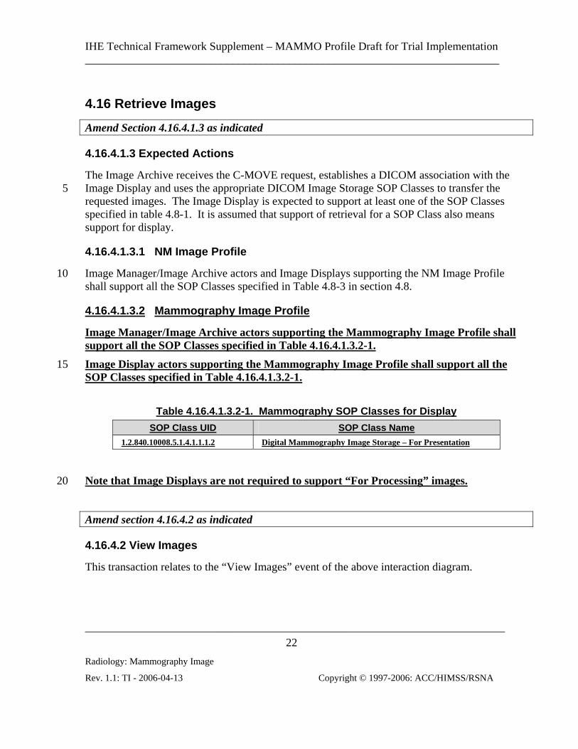
4.16.4.1.3.2 Mammography Image Profile
Image Manager/Image Archive actors supporting the Mammography Image Profile shall support all the SOP Classes specified in Table 4.16.4.1.3.2-1.
Image Display actors supporting the Mammography Image Profile shall support all the 15 SOP Classes specified in Table 4.16.4.1.3.2-1.
Table 4.16.4.1.3.2-1. Mammography SOP Classes for Display
SOP Class UID SOP Class Name 1.2.840.10008.5.1.4.1.1.1.2 Digital Mammography Image Storage – For Presentation
Note that Image Displays are not required to support “For Processing” images. 20
Amend section 4.16.4.2 as indicated
4.16.4.2 View Images
This transaction relates to the “View Images” event of the above interaction diagram.

IHE Technical Framework Supplement – MAMMO Profile Draft for Trial Implementation _________________________________________________________________________
__________________________________________________________________________
Radiology: Mammography Image
Rev. 1.1: TI - 2006-04-13 Copyright © 1997-2006: ACC/HIMSS/RSNA
23
4.16.4.2.1 Trigger Events
The Image Display is requested to display the images.
4.16.4.2.2 Invocation Semantics
This is a local invocation of functions at the Image Display.
4.16.4.2.2.1 Display of Digital X-Ray, Mammography and Intra-Oral Images 5
For the “For Presentation” variant of the Digital X-Ray Image, the Digital Mammography X-Ray Image, and the Digital Intra-oral X-Ray Image, the Image Display actor shall have both the capability to apply all the transformations specified by the VOI LUT Sequence (0028,3010) and the capability to apply all the transformations specified by the Window Width (0028,1051)/Window Center (0028,1050)/VOI LUT Function (0028,1056) attributes in the DX Image Module as selected by the user from the choices available (e.g., guided by Window
10
Center/Width Explanation (0028,1055) or LUT Explanation(0028,3003)) (although not simultaneously).
If VOI LUT Function (0028,1056) is absent, then Window Width (0028,1051)/Window Center (0028,1050) shall be assumed to be the parameters of a linear window operation. 15 VOI LUT Function (0028,1056) values of “SIGMOID” and “LINEAR” shall be supported.
The Image Display actor must also support pixel rendering according to the Grayscale Standard Display Function (GSDF) defined in DICOM 2003 2004 PS 3.14, because the output values of these images are always P-Values.
20 If the DICOM image is referenced by other DICOM composite objects, such as Grayscale Softcopy Presentation States, it is optional for the Image Display to actually retrieve and display/apply these objects.
4.16.4.2.2.1.1 Display of Digital Mammography Images
The contents of this section are required for Image Displays claiming the Mammography Image Profile. 25
The following requirements are intended to establish a baseline level of capabilities. Providing more intelligent and advanced capabilities is both allowed and encouraged and the profile is not intended to be limiting in any way with respect to capabilities. The intention is not to dictate implementation details.
All mammography Image Display actors shall support the Retrieve Images transaction for 30 “For Presentation” images.

IHE Technical Framework Supplement – MAMMO Profile Draft for Trial Implementation _________________________________________________________________________
__________________________________________________________________________
Radiology: Mammography Image
Rev. 1.1: TI - 2006-04-13 Copyright © 1997-2006: ACC/HIMSS/RSNA
24
The Image Display shall be capable of displaying simultaneously a set of current and prior conventional four view screening mammogram images (left and right CC and MLO views).
4.16.4.2.2.1.1.1 Background Air Suppression
Image Display actors shall be capable of recognizing pixels that have the value specified in Pixel Padding Value (0028,0120) when present alone, and between Pixel Padding Value 5 (0028,0120) and Pixel Padding Value Range (0028,eee1) inclusive when both elements are present, and setting them to a minimum display value that is not affected by image contrast adjustments, including inversion of the image contrast.
4.16.4.2.2.1.1.2 Image Orientation and Justification
Image Display actors shall not assume that the pixel data is encoded with an orientation 10 that is suitable for direct display to the user without flipping or rotating into the correct orientation.
The Image Display actor shall use the values of Image Laterality (0020,0062), View Code Sequence (0054,0220), View Modifier Code Sequence (0054,0222) and Patient Orientation (0020,0020) to display images according to the preferred hanging protocol of the current 15 user, rather than depend on descriptive attributes such as Series Description (0008,103E).
The Image Display shall allow the user to select or configure hanging protocols such that given a set of images containing these attributes, the placement of images relative to one another, the required orientation of the images, the display of current and prior images, and the sequence of layouts displayed can be defined. 20
Note that images are normally displayed such that the axilla is towards the top of the viewport, except for cleavage views (which contain two axillas). The location of the axilla can be determined from the direction of the head encoded in Patient Orientation (0020,0020) in the case of lateral and oblique views, and the Image Laterality (0020,0062) in the case of cranio-caudal or caudo-cranial views. For cleavage views, indicated by the 25 presence of a View Modifier Code Sequence (0054,0222) Item containing (R-102D2, SNM3, “Cleavage”), either axilla may be at the top of the view port.
The Image Display shall be able to distinguish and display separately images with one or more Items in a View Modifier Code Sequence (0054,0222) from each other and those without a View Modifier Code Sequence (0054,0222) Item. 30
The Image Display shall be capable of horizontally justifying the image to the left or right side of the viewport rather than centering it, when the aspect ratio (ratio of the number of rows and columns) of the viewport does not match aspect ratio of the image, in order to avoid displaying any unnecessary padding between the adjacent chest walls of back to back

IHE Technical Framework Supplement – MAMMO Profile Draft for Trial Implementation _________________________________________________________________________
__________________________________________________________________________
Radiology: Mammography Image
Rev. 1.1: TI - 2006-04-13 Copyright © 1997-2006: ACC/HIMSS/RSNA
25
images; excessive window decoration (such as scroll bars) shall not be displayed between back to back viewports.
4.16.4.2.2.1.1.3 Image Size
The physical size of the pixels in an image for the purposes of the display modes defined in this section shall be approximated by using the values of Imager Pixel Spacing (0018,1164). 5
The physical size of the pixels in an image for the purposes of distance measurements and the display of a distance caliper shall be approximated by using the values of Imager Pixel Spacing (0018,1164) multipled by Estimated Radiographic Magnification Factor (0018,1114).
For contact (unmagnified) views, the value of Estimated Radiographic Magnification 10 Factor (0018,1114) is typically 1, or close to 1, depending on the distance between the detector side of the compressed breast and the front of the detector housing (the latter being the plane in which Imager Pixel Spacing (0018,1164) is defined), and what depth the nominal location of the object plane is within the compressed breast.
For magnification views, the spacing between the detector side of the compressed breast 15 and the detector is increased substantially relative to the distance to the x-ray source to obtain geometric magnification, and Estimated Radiographic Magnification Factor (0018,1114) will have a value substantially greater than 1.
Pixel Spacing (0028,0030) shall not be used to determine size for the purpose of sizing for display or distance measurements. DICOM CP 586, which clarifies the meaning of Pixel 20 Spacing (0028,0030) values that differ from Imager Pixel Spacing (0018,1164) values when an image has been calibrated by use of a fiducial of known size within the image, is not relevant to mammography applications.
Note that the use of Imager Pixel Spacing (0018,1164) is sufficient regardless of the physical size of the detector used. 25
4.16.4.2.2.1.1.3.1 Same Size
The Image Display shall be capable of displaying multiple images such that all images are at the same relative physical size, regardless of whether they have the same values of Imager Pixel Spacing (0018,1164) or not.
For example, a user reviewing a four-view screening mammogram together with a four-30 view prior mammogram might want to display eight viewports, each showing one view, such that the each view is at the same relative physical size, even if the images were obtained on detectors with different sized pixels. This allows the user to compare features in the prior and current images to visually assess whether or not they have changed in size.

IHE Technical Framework Supplement – MAMMO Profile Draft for Trial Implementation _________________________________________________________________________
__________________________________________________________________________
Radiology: Mammography Image
Rev. 1.1: TI - 2006-04-13 Copyright © 1997-2006: ACC/HIMSS/RSNA
26
Note that it is not expected that the Image Display attempt to compensate for the location of the object within the compressed breast of finite thickness along the x-ray beam, since the convention for measurement from film-screen practice assumes that all objects are located at the cassette (detector) side of the breast.
This mode of display is not intended for comparison of geometrically magnified views at 5 the same time as non-magnified views, since the geometrically magnified view would then be displayed too small.
4.16.4.2.2.1.1.3.2 True Size
The Image Display shall be capable of displaying multiple images such that all images are true size, regardless of whether they have the same values of Imager Pixel Spacing 10 (0018,1164) or not.
True size is defined as the display of an image such that an object in the image when measured with a hand-held ruler on the surface of the display measures as closely as possible to the true physical size of the object if located on the front face of the detector housing. 15
This mode of display is not intended for geometrically magnified views, since the geometrically magnified view would then be displayed too small.
4.16.4.2.2.1.1.3.3 View Actual Pixels
The Image Display shall be capable of displaying multiple images such that each encoded pixel occupies one display pixel in the viewport. 20
If the size of the pixel data exceeds the size of the viewport, it may not be possible to display all of the encoded pixels at once, in which case some form of pan or quadrant navigation functionality shall be provided.
Since there is no minification or magnification, images with different pixel physical size will be displayed in this mode such that the physical size in the patient will appear different. 25
4.16.4.2.2.1.1.4 Image Contrast Adjustment
As described in 4.16.4.2.2.1 Display of Digital X-Ray, Mammography and Intra-Oral Images, the Image Display shall provide the user with the ability to select amongst the available window and VOI LUT choices available in the image object.
Subsequent to the initial application of the chosen contrast transformation, the Image 30 Display actor shall allow the user to adjust the contrast without reverting to a purely linear transformation:

IHE Technical Framework Supplement – MAMMO Profile Draft for Trial Implementation _________________________________________________________________________
__________________________________________________________________________
Radiology: Mammography Image
Rev. 1.1: TI - 2006-04-13 Copyright © 1997-2006: ACC/HIMSS/RSNA
27
• If the chosen contrast transformation is a lookup table, then the Image Display shall allow the input value of the lookup table to be stretched and translated so as to give the affect of adjusting contrast and brightness whilst applying the same general shape as the curve encoded in the lookup table. To provide feedback to the user, the “window width” can be reported as the adjusted range of input values to the LUT, 5 and the “window center” can be reported as the center value of that range.
• If the chosen contrast transformation is a sigmoid shaped VOI LUT Function parameterized by the window center and width, then the Image Display shall allow the window center and width values to be adjusted and a sigmoid function reapplied. 10
If a Display Shutter is present in the image and the Display Shutter is ‘active’ (i.e., the user has turned the display shutter ‘on’) then image contrast manipulations shall be restricted to those pixels within the shutter (i.e., pixels of interest).
If a Pixel Padding Value (0028,0120) is present in the image then image contrast manipulations shall be not be applied to those pixels with the value specified in Pixel 15 Padding Value (0028,0120).
4.16.4.2.2.1.1.5 Annotation of Image Information
Quite apart from good practice, there are nationally-specific requirements for information to be displayed (or displayable) to the user in order to ensure correct identification of the patient and study during reporting and review as well as the resolution of quality issues. 20
This profile defines the union of currently known and anticipated nationally-specific requirements with respect to annotation.
It is desirable that the subset of attributes displayed be configurable by the user or the site.
4.16.4.2.2.1.1.5.1 Annotation of Identification Information
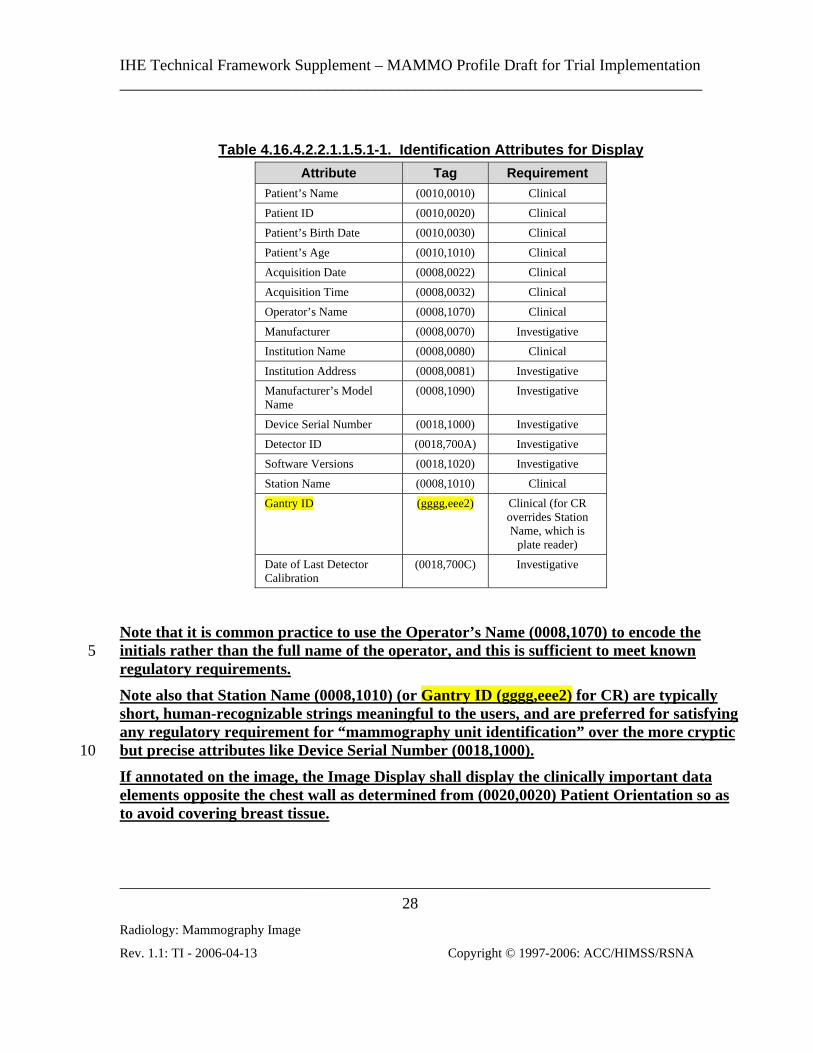
The Image Display shall be capable of displaying the information contained in the 25 attributes listed in Table 4.16.4.2.2.1.1.5.1-1. The required information is defined in two categories:
• Clinical - Those attributes that are useful during interpretation and review of the images for clinical purposes, and which under normal circumstances should be displayed 30
• Investigative - Those attributes that are useful for investigative purposes, such as to trace a quality problem, and which under normal circumstances are a distraction and should not be displayed until requested by the user
IHE Technical Framework Supplement – MAMMO Profile Draft for Trial Implementation _________________________________________________________________________
__________________________________________________________________________
Radiology: Mammography Image
Rev. 1.1: TI - 2006-04-13 Copyright © 1997-2006: ACC/HIMSS/RSNA
28
Table 4.16.4.2.2.1.1.5.1-1. Identification Attributes for Display
Attribute Tag Requirement Patient’s Name (0010,0010) Clinical
Patient ID (0010,0020) Clinical
Patient’s Birth Date (0010,0030) Clinical
Patient’s Age (0010,1010) Clinical
Acquisition Date (0008,0022) Clinical
Acquisition Time (0008,0032) Clinical
Operator’s Name (0008,1070) Clinical
Manufacturer (0008,0070) Investigative
Institution Name (0008,0080) Clinical
Institution Address (0008,0081) Investigative
Manufacturer’s Model Name
(0008,1090) Investigative
Device Serial Number (0018,1000) Investigative
Detector ID (0018,700A) Investigative
Software Versions (0018,1020) Investigative
Station Name (0008,1010) Clinical
Gantry ID (gggg,eee2) Clinical (for CR overrides Station Name, which is
plate reader)
Date of Last Detector Calibration
(0018,700C) Investigative
Note that it is common practice to use the Operator’s Name (0008,1070) to encode the initials rather than the full name of the operator, and this is sufficient to meet known 5 regulatory requirements.
Note also that Station Name (0008,1010) (or Gantry ID (gggg,eee2) for CR) are typically short, human-recognizable strings meaningful to the users, and are preferred for satisfying any regulatory requirement for “mammography unit identification” over the more cryptic but precise attributes like Device Serial Number (0018,1000). 10
If annotated on the image, the Image Display shall display the clinically important data elements opposite the chest wall as determined from (0020,0020) Patient Orientation so as to avoid covering breast tissue.

IHE Technical Framework Supplement – MAMMO Profile Draft for Trial Implementation _________________________________________________________________________
__________________________________________________________________________
Radiology: Mammography Image
Rev. 1.1: TI - 2006-04-13 Copyright © 1997-2006: ACC/HIMSS/RSNA
29
The Image Display shall make the investigative set of values available to the ordinary user, but these need not necessarily be annotated directly on the image, e.g., they might be displayed in a separate pop-up window.
It shall be possible to turn on or off either set of annotations at the user’s discretion.
4.16.4.2.2.1.1.5.2 Annotation of Technical Factor Information 5
Good practice dictates that certain technical factors be displayed (or displayable) to the user in order to detect and resolve quality issues.
In addition, there are technical factors that are unique to the digital realm. One such factor is related to the adjustment of the sensitivity and/or dynamic range of the sensor or processing, corresponding to the amount of radiation reaching the detector. These are 10 variously referred to by manufacturers as ADU, exposure index, or sensitivity. Note that interpretation of this value is vendor-specific, though may be standardized in the future by AAPM.
The Image Display shall be capable of displaying the information contained in the attributes listed in Table 4.16.4.2.2.1.1.5.2-1. 15
Table 4.16.4.2.2.1.1.5.2-1. Technique Attributes for Display
Attribute Tag KVP (0018,0060)
Exposure (0018,1152)
Exposure Time (0018,1150)
Filter Material (0018,7050)
Anode Target Material (0018,1191)
Compression Force (0018,11A2)
Body Part Thickness (0018,11A0)
Positioner Primary Angle (0018,1510)
Relative X-ray Exposure (0018,1405)
Entrance Dose in mGy (0040,8302)
Organ Dose (0040,0316)
If annotated on the image, the Image Display shall be capable of displaying these data elements opposite the chest wall as determined from (0020,0020) Patient Orientation so as 20 to avoid covering breast tissue.
It shall be possible to turn on or off the annotations at the user’s discretion.

IHE Technical Framework Supplement – MAMMO Profile Draft for Trial Implementation _________________________________________________________________________
__________________________________________________________________________
Radiology: Mammography Image
Rev. 1.1: TI - 2006-04-13 Copyright © 1997-2006: ACC/HIMSS/RSNA
30
4.16.4.2.2.1.1.5.3 Annotation of View Information
Traditional film-screen practice requires the use of lead markers consisting of letters encoding the type of view, located in the corner of the film that is opposite the chest wall and towards the axilla.
Image Displays shall mimic this practice by annotating the viewport with abbreviations 5 derived from the value of Image Laterality (0020,0062), View Code Sequence (0054,0220) and any values of View Modifier Code Sequence (0054,0222) Items that are present.
Unless otherwise overridden by nationally specific extensions, the specific abbreviations to be displayed are as defined in the View Modifier Abbreviations Column of CID 4014 and CID 4015 of DICOM PS 3.16, which is derived from ACR MQCM 1999, with the following 10 clarifications:
• The Image Laterality shall be prepended to the abbreviation, e.g., a right CC view shall be displayed as “RCC”
• A CC view with a cleavage modifier shall be annotated as only “CV” if Image Laterality has a value of “B”, i.e., the “CC” shall not be displayed, and the laterality 15 shall be omitted (in which case the left and right breast can be determined from the value of Patient Orientation (0020,0020)); otherwise “LCV” or “RCV” shall be used
• A right MLO view with the axillary tail modifier shall be annotated only as “RAT”, i.e., the “MLO” shall not be displayed
• The implant displaced modifier shall be appended as a suffix to the view, as if it 20 were defined as “…ID”, e.g., a right implant displaced CC view would be annotated as “RCCID”
• A spot compression modifer shall be prepended as a prefix to the view, as if it were defined as “S…”, e.g., a left spot compression CC view would be annotated as “LSCC” 25
• A tangential modifier shall be annotated as only “TAN”, i.e., the “CC” or whatever else is encoded as the view, shall not be displayed
• When multiple prefix or suffix modifiers are present, they shall be sorted alphabetically, e.g. a right magnified, spot compression, implant displaced, rolled lateral CC view would be annotated as “RMSCCIDRL” 30
Spaces and other delimiters are permitted between components of the abbreviations.
Prior to any flip or rotation for display, the location of the corner opposite the chest wall and towards the axilla can be determined from the direction of the chest wall encoding in Patient Orientation (0020,0020), regardless of view, and the direction of the head encoded

IHE Technical Framework Supplement – MAMMO Profile Draft for Trial Implementation _________________________________________________________________________
__________________________________________________________________________
Radiology: Mammography Image
Rev. 1.1: TI - 2006-04-13 Copyright © 1997-2006: ACC/HIMSS/RSNA
31
in Patient Orientation (0020,0020) in the case of lateral and oblique views, and the Image Laterality (0020,0062) in the case of cranio-caudal or caudo-cranial views. For cleavage views, the axilla at the top of the viewport shall be annotated. See also 4.16.4.2.2.1.1.2 Image Orientation and Justification.
It shall be possible to turn on or off the annotations at the user’s discretion. 5
4.16.4.2.2.1.1.6 Annotation of Size Information
For the purpose of this section, physical pixel size is as defined in Section 4.16.4.2.2.1.1.3 Image Size.
The user needs to be aware when the displayed image does not reflect a 1:1 rendition of an encoded image pixel to a displayed pixel, i.e., that some magnification or minification has 10 taken place. Anything other than 1:1 rendition may result in loss or distortion of information.
Further, the user needs to be aware of whether or not the image is displayed at true size, and whether or not different images are at the same relative physical size.
Therefore, the Image Display shall be capable of annotating the displayed images with the 15 following:
• Number of displayed pixels relative to the number of encoded image pixels, such that a factor of 1.0 (or 100%) means 1:1 rendition, a factor of less than 1.0 means that one pixel on the display represents more than one pixel in the encoded image (minification), and a factor of greater than 1.0 means that pixels in the encoded 20 image have been replicated or interpolated to span multiple displayed pixels (magnification)
• Size of the displayed pixels relative to true size, such that a factor of 1.0 (or 100%) means true size, a factor of less than 1.0 means smaller than true size, and a factor of greater than 1.0 means larger than true size 25
The exact form and description of these two relative pixel size indications is left to the discretion of the implementor.
The Image Display shall be capable of displaying a ruler or caliper indicating the physical size of the displayed image, for the purpose of providing a visual cue to the user of the general size of the features in the image. It shall be possible to turn on or off the ruler at the 30 user’s discretion.
The Image Display shall provide a means of accurately measuring distance between two points based on the physical size of the image pixels.

IHE Technical Framework Supplement – MAMMO Profile Draft for Trial Implementation _________________________________________________________________________
__________________________________________________________________________
Radiology: Mammography Image
Rev. 1.1: TI - 2006-04-13 Copyright © 1997-2006: ACC/HIMSS/RSNA
32
4.16.4.2.2.1.1.7 Partial View Option
If the Image Display supports the Partial View Option, it shall additionally annotate the displayed image in the view port to indicate:
• when the image is a partial view, as defined by the presence of Attribute Partial View (0028,1350) with a value of YES 5
• which region of the mosaic the image represents, as encoded in Partial View Code Sequence (0028,1352), if present
Whether or not this annotation is textual or in the form of some iconic graphic representation, and whether or not any navigational or layout assistance is provided for the entire mosaic is at the discretion of the implementor. 10
4.16.4.2.2.1.1.8 Display of CAD Marks
Image Displays shall be able to apply marks on the displayed image corresponding to all findings encoded in Mammography CAD SR objects with a (111056, DCM, “Rendering Intent”) value of (111150, DCM, “Presentation Required”). They may be able to display additional findings that have a with a (111056, DCM, “Rendering Intent”) value of 15 (111151, DCM, “Presentation Optional”).
The Image Display shall make the user aware that CAD marks are available for display, and indicate whether or not CAD marks are currently activated. If more than one set of CAD objects are available that are applicable to the same image (e.g. CAD was run more than once on the same images), then all shall be made available for display at the user’s 20 discretion.
The Image Display shall be able to apply the marks to “For Presentation” images that are referenced by the Mammography CAD SR SOP Instance.
The Image Display shall also be able to apply the marks to “For Presentation” images whose Source Image Sequence references the SOP Instance UID of the “For Processing” 25 images that are referenced by the Mammography CAD SR SOP Instance, unless the Spatial Locations Preserved (0028,135A) is present in the Source Image Sequence Item and has a value of NO.
The Patient Orientation of the images referenced in the Source Image Sequence encoded in (111044, DCM, “Patient Orientation Row”) and (111043, DCM, “Patient Orientation 30 Column”) of the Mammography CAD SR SOP Instance shall be used to transform (flip or rotate) the coordinates of the CAD marks if it differs from the Patient Orientation (0020,0020) of the corresponding “For Presentation” image.

IHE Technical Framework Supplement – MAMMO Profile Draft for Trial Implementation _________________________________________________________________________
__________________________________________________________________________
Radiology: Mammography Image
Rev. 1.1: TI - 2006-04-13 Copyright © 1997-2006: ACC/HIMSS/RSNA
33
The form in which the CAD marks are displayed may influence observer performance, and hence it may be necessary to display them in a manner prescribed by the CAD device vendor, which is not encoded in the DICOM object. The form of the CAD mark rendering is out of the scope of this profile to define.
The Image Display shall make available for display the following information about each 5 CAD finding, if encoded in the CAD object:
• Manufacturer (0008,0070)
• Algorithm as defined in (111001, DCM, “Algorithm Name”) and (111003, DCM, “Algorithm Version”)
• Operating point as defined in (111071, DCM, “CAD Operating Point”) 10
• Content Date (0008,0023) and Content Time (0008,0033) of the CAD SR instance, if more than one exists and applies to the displayed image
The Image Display shall indicate when CAD was not attempted or has failed, either entirely, or if some algorithms have succeeded and others failed, as distinct from when CAD has succeeded but there are no findings. This information shall be obtained from the 15 status values of (111064, DCM, “Summary of Detections”) and (111065, DCM, “Summary of Analyses”).
4.16.4.2.2.1.1.9 Post-Processing of For Presentation Images
This profile does not constrain the ability of the Image Display to further post-process “For Presentation” images, for example with edge enhancement or noise reduction. 20
However, there shall be a mode in which actual pixels of “For Presentation” images are displayed not only with 1:1 display to encoded pixel size, but with no further processing or interpolation other than application of point grayscale transformations.
4.16.4.2.2.1.1.10 Accidental reading of prior studies
There is a significant risk that during primary interpretation the most recently available 25 prior study on the Image Display will be interpreted by the user as the current study, if for some reason the current study is not available.
Accordingly, it is required that an Image Display explicitly warn the user if none of the studies being displayed are within a user configurable period from the current real time, as determined by Acquisition Date (0008,0022). 30

IHE Technical Framework Supplement – MAMMO Profile Draft for Trial Implementation _________________________________________________________________________
__________________________________________________________________________
Radiology: Mammography Image
Rev. 1.1: TI - 2006-04-13 Copyright © 1997-2006: ACC/HIMSS/RSNA
34
5
10
15
4.23 Print Request with Presentation LUT This section corresponds to Transaction RAD-23 of the IHE Technical Framework. Transaction RAD-23 is used by the Print Composer and Print Server actors.
4.23.1 Scope
This transaction supports the capability of the Print Composer to ensure display consistency for images rendered by the Print Server. The Print Composer sends a DICOM Print Request to the Print Server. The request includes the specification of a Presentation Look Up Table (LUT) to be applied to the image data at the Film Box level. The Print Composer will be the DICOM Print SCU and the Print Server will be the DICOM Print SCP.
…
Print Composer Print Server
Print Request withPresentation LUT
4.23.4.2 DICOM Presentation LUT N-CREATE
The Presentation LUT data specified by this N-CREATE will be used to transform the image data at the film box level to realize specific image display characteristics suitable to the Print Composer. In addition, this message can use the Presentation LUT Shape Attribute to specify a pre-defined Presentation LUT Shape (The Presentation LUT Shape value of “LIN OD” will not be supported for the IHE Technical Framework, except for the Mammography Image Profile (see 4.23.4.8)). Presentation LUT information will only be specified and applied at the Film Box level. .

IHE Technical Framework Supplement – MAMMO Profile Draft for Trial Implementation _________________________________________________________________________
__________________________________________________________________________
Radiology: Mammography Image
Rev. 1.1: TI - 2006-04-13 Copyright © 1997-2006: ACC/HIMSS/RSNA
35
5
10
Note: In the event a Print Composer chooses to specify a Presentation LUT Shape of IDENTITY instead of a Presentation LUT then the image data will be sent to the Print Server in the form of P-values for interpretation by the Print Server according to the GSDF.
Note: Print composers are encouraged to use the procedures defined in Appendix B of DICOM Part 14 or other equivalent procedures to make calibration measurements. Where these data are not available, Print Composers may use the suggested default values specified in Part 14 of the DICOM standard for the attributes of Illumination (2010,015E) and Reflected Ambient Light (2010,0160). For transmissive hardcopy printers the standard recommends 2000 cd/m² for Illumination and 10 cd/m² for reflected ambient light. For reflective hardcopy printers the standard recommends 150 cd/m² for Illumination (maximum luminance obtainable from diffuse reflection of the illumination present.) These values are also consistent with those used in the illustrative examples in Annex D of Part 14 of the standard.
4.23.4.8 Mammography Image Profile 15
Requirements specific to print are specified for mammography since there are regulatory requirements in many jurisdictions with respect to the need to provide the patient with images of primary diagnostic quality that are appropriately annotated.
Print Composers participating in the Mammography Image Profile shall:
• Be capable of true size printing of all the pixels of a single view per sheet of film 20 based on the value stored in Imager Pixel Spacing (0018, 1164) in the Mammography Image SOP Instances being printed, so that distance measurements made optically on the printed film will be approximately equivalent to those made on a film-screen mammography exposure, and shall use Requested Image Size (2020,0030) to command the Print Server to use the correct image size. Note that the 25 Imager Pixel Spacing (0018, 1164) should not be corrected by Estimated Radiographic Magnification Factor (0018,1114), since doing so for magnified views would not only exceed the size of the available print area, but would deviate from the accepted film-screen practice.
• Be capable of justifying the images in the print request such that the chest wall will 30 be printed as close to the edge of the film as the Print Server is capable.
• Be capable of sending the Maximum Density attribute (2010,0130)
• Be capable of burning into the pixel data sent to the Print Server all the annotations defined in the clinical set for Image Displays in 4.16.4.2.2.1.1.5.1 Annotation of Identification Information, and additionally Institution Address (0008,0081), 35

IHE Technical Framework Supplement – MAMMO Profile Draft for Trial Implementation _________________________________________________________________________
__________________________________________________________________________
Radiology: Mammography Image
Rev. 1.1: TI - 2006-04-13 Copyright © 1997-2006: ACC/HIMSS/RSNA
36
4.16.4.2.2.1.1.5.2 Annotation of Technical Factor Information and 4.16.4.2.2.1.1.5.3 Annotation of View Information
• Be capable of burning a ruler, caliper or other form of distance scale into the pixel data sent to the Print Server
• Be capable of transmitting a pixel data bit depth of 12 bits to the Print Server (i.e., 5 an 8 bit path is not sufficient for mammography)
• Be capable of burning into the pixel data sent to the Print Server a VOI LUT transformation (linear, sigmoid or tabular) as selected by the user from those available in the original image or as otherwise provided by the user
Print Servers participating in the Mammography Image Profile shall: 10
• Print on transmissive media
• Be capable of true size printing based on the Requested Image Size (2020,0030) and shall attain the requested size with a precision of a maximum 2% error in linear distance (this precision requirement is chosen based not any implied or required accuracy of measurements from film or projection radiography, but rather because 15 current electrical, mechanical and optical technology readily allows for this precision, and deviation beyond this value indicates a fundamental flaw in the implementation of the protocol or logic)
• Be capable of printing with a border between the chest wall edge of the digital mammography image and the physical edge of the film no greater than 5mm, so 20 that the printed films can be hung on a light box with the chest wall edges of corresponding views directly abutted.
• Be capable of applying the Maximum Density attribute (2010,0130) in the request, and printing with a maximum optical density no less than 3.5
• Be capable of receiving a pixel data bit depth of 12 bits from the Print Composer 25 (i.e., an 8 bit path is not sufficient for mammography).
• Be capable of using a Presentation LUT Shape value of “IDENTITY” and “LIN OD” and the Presentation LUT Sequence (2050,0010)
Note that support for a Presentation LUT Shape value of “LIN OD” by Print Servers is 30 specified for Mammography since the expected transmitted illumination of mammography view boxes on which printed film may be hung exceeds the range of illumination for which the Barten model is defined, and hence it may be difficult to achieve consistency between prints, and between prints and displays. It allows the Print Composer to use “LIN OD” to

IHE Technical Framework Supplement – MAMMO Profile Draft for Trial Implementation _________________________________________________________________________
__________________________________________________________________________
Radiology: Mammography Image
Rev. 1.1: TI - 2006-04-13 Copyright © 1997-2006: ACC/HIMSS/RSNA
37
have greater control over the optical density of the printed film, and to take what action is necessary to result in consistency of appearance for the anticipated viewing conditions.

IHE Technical Framework Supplement – MAMMO Profile Draft for Trial Implementation _________________________________________________________________________
__________________________________________________________________________
Radiology: Mammography Image
Rev. 1.1: TI - 2006-04-13 Copyright © 1997-2006: ACC/HIMSS/RSNA
38
Volume 3 – Transactions

IHE Technical Framework Supplement – MAMMO Profile Draft for Trial Implementation _________________________________________________________________________
__________________________________________________________________________
Radiology: Mammography Image
Rev. 1.1: TI - 2006-04-13 Copyright © 1997-2006: ACC/HIMSS/RSNA
39
5
10
15
4.43 Evidence Document Stored This section corresponds to Transaction RAD-43 of the IHE Technical Framework. Transaction RAD-43 is used by the Acquisition Modality and Evidence Creator actors.
4.43.1 Scope
In the Evidence Documents Stored transaction, the Acquisition Modality or the Evidence Creator transmits an Evidence Document, which is stored in the Image Archive.
Evidence Documents are DICOM composite objects that are produced as a result of performing procedure steps such as image acquisition, image processing or computer-aided detection.
These objects are intended to serve as evidence for diagnostic interpretation; however, they are not images but rather DICOM Structured Reporting documents. Evidence Documents represent the uninterpreted information which is primarily managed and used inside imaging department, although distribution outside Radiology is not precluded. Such objects are not expected to be managed by the Report Manager. Objects encoded as SOP Instances of such SOP classes as Mammography CAD are examples of Evidence documents.
4.43.2 Use Case Roles
Evidence Document Stored
Acquisition Modality
Evidence Creator
Image Archive
Actor: Acquisition Modality
Role: Records non-imaging evidence information in the Evidence Documents and stores them to the Image Archive.
Actor: Evidence Creator 20
Role: Records non-imaging evidence information in the Evidence Documents and stores them to the Image Archive.
Actor: Image Archive

IHE Technical Framework Supplement – MAMMO Profile Draft for Trial Implementation _________________________________________________________________________
__________________________________________________________________________
Radiology: Mammography Image
Rev. 1.1: TI - 2006-04-13 Copyright © 1997-2006: ACC/HIMSS/RSNA
40
Role: Accepts and Stores Evidence Document Instances received from the Acquisition Modality or Evidence Creator.
4.43.3 Referenced Standards
DICOM 20032004 PS 3.4: Storage Service Class; Basic Text SR SOP Class; Enhanced SR SOP Class; Comprehensive SR SOP Class; Chest CAD SR SOP Class; Mammography CAD SR SOP Class; OB-GYN Ultrasound Procedure Reports; Catheterization Lab SR; Vascular
5
Ultrasound SR.
DICOM Supplement 26: OB-GYN Ultrasound Procedure Reports.
DICOM Supplement 66: Catheterization Lab SR
DICOM Supplement 71: Vascular Ultrasound SR 10
Note: Supplements 66 and 71 are not final as of date of this publication as they await harmonization of small sets of codes. As soon as this harmonization is completed, it is expected that the supplements will be approved for final text. This list is intended to provide a base list of examples. It is expected that DICOM will continue to publish additional SR SOP Classes and Templates appropriate for Evidence Documents. 15
4.43.4 Interaction Diagram
Evidence Document Stored
Acquisition Modality
Image Archive Evidence
Creator
Evidence Document Stored
(C-STORE) (C-STORE)
4.43.4.1 Evidence Document Stored
This transaction relates to the “DICOM C-STORE” event between the Acquisition modality or the Evidence Creator and the Image Archive in the above interaction diagram. 20
4.43.4.1.1 Trigger Events
The Acquisition Modality or the Evidence Creator generates Evidence Documents that need to be archived.

IHE Technical Framework Supplement – MAMMO Profile Draft for Trial Implementation _________________________________________________________________________
__________________________________________________________________________
Radiology: Mammography Image
Rev. 1.1: TI - 2006-04-13 Copyright © 1997-2006: ACC/HIMSS/RSNA
41
5
4.43.4.1.2 Message Semantics
The Acquisition Modality or the Evidence Creator uses the DICOM C-STORE message to transfer the Evidence Documents (as SR objects) to the Image Archive for storage. The Acquisition Modality or the Evidence Creator is the DICOM Storage SCU and the Image Archive is the DICOM Storage SCP.
It is a requirement that certain information be recorded in the Evidence Document header. The details of mapping such information to DICOM SOP instances are specified in Volume III, Appendix C, Table C.1-1.
4.43.4.1.3 Expected Actions
The DICOM Standard (20012004) defines a number of non-image storage SOP classes that may be used for creation of Evidence Documents. It is expected that the Image Archive will support multiple storage SOP classes as defined in table 4.43-1 below.
10
Table 4.43-1. Suggested Evidence Document SOP Classes SOP Class UID SOP Class Name
1.2.840.10008.5.1.4.1.1.88.50 Mammography CAD SR
1.2.840.10008.5.1.4.1.1.88.11 Basic Text SR
1.2.840.10008.5.1.4.1.1.88.22 Enhanced SR
1.2.840.10008.5.1.4.1.1.88.33 Comprehensive SR
1.2.840.10008.5.1.4.1.1.88.65 Chest CAD SR
15 It is also expected that the Image Archive will support one or more Templates that are defined to be used with the Evidence Documents, as specified in the Table 4.43-2.
Table 4.43-2. Suggested Evidence Document Templates Template ID Template Name
TID 4000 Mammography CAD Document Root Template
TID 5000 OB-GYN Ultrasound Procedure Report
TID 3500 Hemodynamics Report
TID 4100 Chest CAD SR Document Root Template
TID 5100 Vascular Ultrasound Procedure Report Template
The Image Archive must support storage level 2: i.e., all type 3 attributes must be supported.

IHE Technical Framework Supplement – MAMMO Profile Draft for Trial Implementation _________________________________________________________________________
__________________________________________________________________________
Radiology: Mammography Image
Rev. 1.1: TI - 2006-04-13 Copyright © 1997-2006: ACC/HIMSS/RSNA
42
4.43.4.1.3.1 Mammography Image Profile
Evidence Creator and Image Manager/Image Archive actors supporting the Mammography Image Profile shall support the Mammography CAD SR SOP Class.
In particular, CAD systems (acting as Evidence Creators) performing analysis on Mammography images shall be able to return their results in Mammography CAD SR 5 SOP Class instances. This does not preclude them from additionally creating Presentation States and/or Secondary Capture or Mammography images.
Also, Image Manager/Image Archive actors shall not only be able to receive Mammography CAD SR SOP Class objects from the Evidence Creator, but also be able to return them in response to queries (i.e., they must actually be stored intact for later 10 retrieval, not merely processed or burned in to images dynamically). See Retrieve Evidence Transaction Section 4.45.4.2.3.1 Mammography Image Profile.

IHE Technical Framework Supplement – MAMMO Profile Draft for Trial Implementation _________________________________________________________________________
__________________________________________________________________________
Radiology: Mammography Image
Rev. 1.1: TI - 2006-04-13 Copyright © 1997-2006: ACC/HIMSS/RSNA
43
5
4.44 Query Evidence Documents This section corresponds to Transaction RAD-44 of the IHE Technical Framework. Transaction RAD-44 is used by the Image Archive and Image Display actors.
4.44.1 Scope
This section describes the sequence of Transactions required for the Image Display to query the Image Archive for instances of Evidence Documents.
4.44.2 Use Case Roles
Query Evidence
Image Display
Image Archive
Actor: Image Display
Role: Query for Evidence Documents objects (generally in order to retrieve them). 10
Actor: Image Archive
Role: Respond to queries from the Image Display for Evidence Documents objects.
4.44.3 Referenced Standards
DICOM 2003 2004 PS 3.4: Query/Retrieve Service Class

IHE Technical Framework Supplement – MAMMO Profile Draft for Trial Implementation _________________________________________________________________________
__________________________________________________________________________
Radiology: Mammography Image
Rev. 1.1: TI - 2006-04-13 Copyright © 1997-2006: ACC/HIMSS/RSNA
44
4.44.4 Interaction Diagram
Query Responses (C-FIND)
Image DisplayImage Archive
Query Evidence Documents (C-FIND)
4.44.4.1 Query Evidence Documents
The Query (Study Root – FIND and optionally Patient Root – FIND) SOP Classes shall be supported. Refer to DICOM 2003 2004 PS 3.4: Query/Retrieve Service Class for detailed descriptive semantics.
5
10
15
20
4.44.4.1.1 Trigger Events
Image Display needs to obtain information about Evidence Documents.
4.44.4.1.2 Message Semantics
The message semantics are defined by the DICOM Query/Retrieve SOP Classes.
A C-FIND Request from the DICOM Study Root Query/Retrieve Information Model – FIND SOP Class or the DICOM Patient Root Query/Retrieve Information Model – FIND SOP Class shall be sent from the Image Display to the Image Archive.
The Image Display uses one or more matching keys as filter criteria to obtain the list of matching entries in the Image Archive at the selected level (Patient & Study/Series/Instance).
In addition to the required and unique keys defined by the DICOM Standard, the IHE Technical Framework has defined matching and return keys to be supported by query SCUs and SCPs. The keys are defined in section 4.14.4.1.2 and table 4.14-1. The conventions for key usage are defined in RAD TF-2: 2.2. For the Image Display (SCU) and the Image Archive (SCP) the additional Evidence Document Instances specific keys are defined in table 4.44-1.
Table 4.44-1. Evidence Document Instance Specific Query Matching and Return Keys
Query Keys Matching Query Keys Return Attribute Name Tag SCU SCP SCU SCP

IHE Technical Framework Supplement – MAMMO Profile Draft for Trial Implementation _________________________________________________________________________
__________________________________________________________________________
Radiology: Mammography Image
Rev. 1.1: TI - 2006-04-13 Copyright © 1997-2006: ACC/HIMSS/RSNA
45
Query Keys Matching Query Keys Return Evidence Document Instance Specific Level Content Date (0008,0023) O O O R+
Content Time (0008,0033) O O O R+
Referenced Request Sequence (0040,A370)
>Study Instance UID (0020,000D) O O R+* R+
>Accession Number (0008,0050) O O R+ R+
>Requested Procedure ID (0040,1000) O O R+ R+
>Requested Procedure Code Sequence
(0032,1064)
>>Code Value (0008,0100) O O O R+
>>Coding Scheme Designator (0008,0102) O O O R+
>>Coding Scheme Version (0008,0103) O O O R+
>>Code Meaning (0008,0104) O O O R+
Content Template Sequence (0040,A504)
>Template Identifier (0040,DB00) O O R+ R+
Concept Name Code Sequence (0040,A043) >Code Value (0008,0100) O O R+* R+
>Coding Scheme Designator (0008,0102) O O R+* R+
>Coding Scheme Version (0008,0103) O O O R+
>Code Meaning (0008,0104) O O R+ R+
4.44.4.1.3 Expected Actions
The Image Archive receives the C-FIND request, performs the matching on the provided keys and sends the list of matching records back to the Image Display via C-FIND responses.
The Image Display is expected to use the Template ID to select Evidence Documents for retrieval that it supports. 5
4.44.4.1.3.1 Mammography Image Profile
Image Display and Image Manager/Image Archive actors supporting the Mammography Image Profile shall support the Mammography CAD SR SOP Class.

IHE Technical Framework Supplement – MAMMO Profile Draft for Trial Implementation _________________________________________________________________________
__________________________________________________________________________
Radiology: Mammography Image
Rev. 1.1: TI - 2006-04-13 Copyright © 1997-2006: ACC/HIMSS/RSNA
46
5
4.45 Retrieve Evidence Documents This section corresponds to Transaction RAD-45 of the IHE Technical Framework. Transaction RAD-45 is used by the Image Display and Image Archive actors.
4.45.1 Scope
In the Retrieve Evidence Documents Transaction, the requested DICOM Evidence Documents are transferred from the Image Archive to the Image Display.
4.45.2 Use Case Roles
Retrieve Evidence Documents
Image DisplayImage Archive
Actor: Image Archive:
Role: Sends requested Evidence Documents to the Image Display Actor. 10
Actor: Image Display
Role: Receives requested Evidence Documents from the Image Archive Actor.
4.45.3 Referenced Standards
DICOM 2003 2004 PS 3.4: Query/Retrieve Service Class, Storage SOP Class

IHE Technical Framework Supplement – MAMMO Profile Draft for Trial Implementation _________________________________________________________________________
__________________________________________________________________________
Radiology: Mammography Image
Rev. 1.1: TI - 2006-04-13 Copyright © 1997-2006: ACC/HIMSS/RSNA
47
4.45.4 Interaction Diagram
Store Evidence Documents (C-STORE)
Retrieve Evidence documents (C-MOVE)
Image DisplayImage Archive
Render Evidence Documents
4.45.4.1 Retrieve Evidence Documents
The Retrieve (Study Root – MOVE and optionally Patient Root - MOVE) SOP Classes shall be supported. The Image Archive as an SCU shall support DICOM Storage SOP Classes that may be used as Evidence Documents. Refer to DICOM
5 2003 2004 PS 3.4, Annex C, for detailed
descriptive semantics (see vol. III, table 4.38-1).
4.45.4.1.1 Trigger Events
The Image Display selects specific Evidence Document objects to retrieve from the Image Archive. 10
4.45.4.1.2 Message Semantics
The message semantics are defined in the DICOM Query/Retrieve Service Class section of the DICOM 2003 2004 PS 3.4: Query/Retrieve Service Class. It is the responsibility of the Image Manager to assure that the patient and procedure information is current in the Evidence Document objects when they are retrieved from the Image Archive. 15
20
4.45.4.1.3 Expected Actions
The Image Archive receives the C-MOVE request, establishes a DICOM association with the Image Display, and uses the DICOM C-STORE command to transfer the requested Evidence Document objects.
Since the Image Display can select compatible documents based on the Template IDs returned in the query, the Image Display is required not to return an error to the Image Archive due to the retrieved document content. The retrieved results may simply be discarded instead.

IHE Technical Framework Supplement – MAMMO Profile Draft for Trial Implementation _________________________________________________________________________
__________________________________________________________________________
Radiology: Mammography Image
Rev. 1.1: TI - 2006-04-13 Copyright © 1997-2006: ACC/HIMSS/RSNA
48
5
10
15
20
25
4.45.4.2 Render Evidence Documents
This transaction relates to the “Render Evidence Documents” event of the above interaction diagram.
4.45.4.2.1 Trigger Events
The Image Display receives Evidence Document instances from the Image Archive
4.45.4.2.2 Invocation Semantics
This is a local invocation of functions resident within the Image Display. Evidence Documents shall be displayed to the user of the Image Display. The method used by the Image Display to present Evidence Documents for viewing by the user is outside the scope of the IHE Technical Framework. For example, in the case when an Image Display is grouped with an Evidence Creator, the Evidence Document may be rendered as input for further processing by the Evidence Creator.
4.45.4.2.3 Expected Actions
The Image Display renders the Evidence Documents retrieved. If the Image Display is unable to handle parts of the document, it may inform the user and offer the choice of doing a “low-grade” rendering or ignoring the data.
Evidence Documents may contain references to other types of evidence objects. The Image Display shall always be able to render (or “low-grade” render) referenced Evidence Documents or to invoke other rendering display functionality.
If the Image Display also supports the Consistent Presentation of Images Profile, it is also required to apply any presentation states referenced in the Evidence Document for application to the relevant images.
If the Image Display also supports the Key Image Notes Profile, it is also required to render any Key Image Notes referenced in the Evidence Document.
Note: It is recommended to use the just retrieved instance of the Evidence Document to ensure that the most recent patient data be displayed to reflect possible patient merge and patient update in the Image Manager/Image Archive. This patient data may be inconsistent with patient data contained in a previously retrieved copy of the same Evidence Document instance.
4.45.4.2.3.1 Mammography Image Profile 30
Image Display and Image Manager/Image Archive actors supporting the Mammography Image Profile shall support the Mammography CAD SR SOP Class.

IHE Technical Framework Supplement – MAMMO Profile Draft for Trial Implementation _________________________________________________________________________
__________________________________________________________________________
Radiology: Mammography Image
Rev. 1.1: TI - 2006-04-13 Copyright © 1997-2006: ACC/HIMSS/RSNA
49
Image Display actors shall be able to apply Mammography CAD SR information to displayed images; see 4.16.4.2.2.1.1.8 Display of CAD Marks. It is not permitted to ignore data that has a rendering intent of presentation required; there is no such thing as a “low-grade” rendering for Mammography CAD SR.
5